Download to read offline

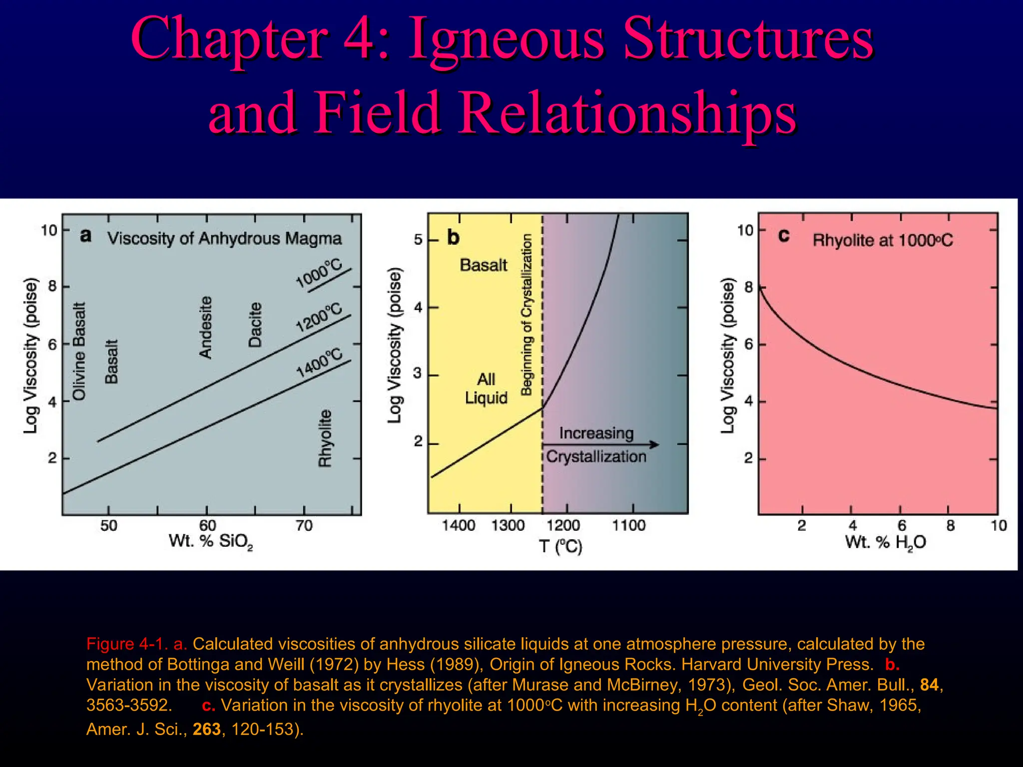
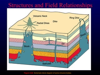
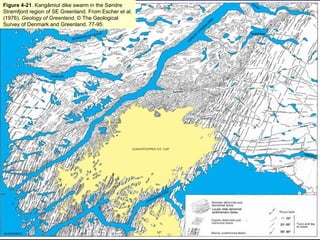
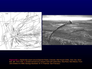
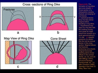
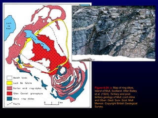
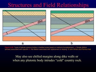
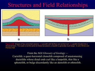
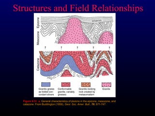
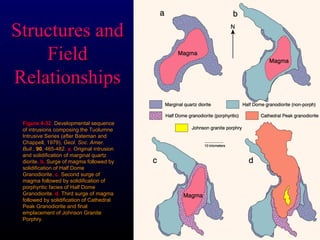
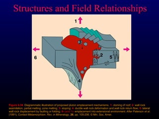

Chapter 4 focuses on igneous structures and their field relationships, detailing the properties of various silicate liquids and the behavior of basalt and rhyolite as they crystallize. It includes diagrams of intrusive bodies, like radial and ring dikes, and explains mechanisms of magma intrusion such as stoping and wall rock assimilation. Additionally, it discusses characteristics of plutons in different geological zones and outlines the developmental sequence of intrusions in the Tuolumne intrusive series.


![ANIMAL_CELL_,_TISSUE_AND_ORGAN_CULTURE[1].pptx](https://cdn.slidesharecdn.com/ss_thumbnails/animalcelltissueandorganculture1-260204172026-4462b440-thumbnail.jpg?width=640&height=640&fit=bounds)


