Download to read offline


![w
w
w
.exam
race.com
43.
44.
·15.
A. Zener DioJe
R. Pin Diode
C. Tunnd Diudc
D. 1nractor Diode
Lis t II
I. Pust-switchiog circuits
2. Microwave switches
3. Local oscilhuors for radars
4. Frequency conveners
5. Voltage regulators
A B c D
a. 5 2 I 4
b. I 2 5 ,,
c. 5 3 I 2
d. I 3 5 1
The open cirtmit impednnce nf n certain
length ofa lossless line is IOOfl. Th~ shun
circuit impcclancc of the SilmC line is also
100!1. The characterisrk impedance ofthe
Iinc- is
a. 100~0
b. 5() Q
e. 1110/ ~0
d. lOOn
Asst>rtioo (A): 1l1e relauousltip between
MugMtic Vocllr polcllli>d A rutcl lh<
Curreu den>ity J in free ~pace i<
I x (17 xA)=~J,,J. ~or a magnetic licld in
free space due to a de or sl~wly vruying
clln'enl is '1,A=-11~J
R"'"'"" (R): Fo•· magtleti" field due 10 d"
or s.lowly varyingcurrent 'J]i ~ 0_
a. Bnth A unci R ;Ire tme and R is the
conect explanation of A
b. Buth 1 and R are lrle but R is NOT
the correct exphmation ofA
e. A is tn•e hut R i> raise
d. A is false llllt R is true
- - ;;jj
Given that 'fJ" H ~.! ~
ol
Assertion (A.): ]Jl the equmion, Lhe
ndditionnI term aois necessouv.
at •
Reu~un (R): The cqllation will be
cunsisknl With the principle .,,-
conservation ofcharge.
1. BQth i and R arc true and R is th"
correct explanati0n ofA
h. B<lth A lind I~ arc tnte but R i~ NO'I
the correct explanation ofA
c. A is u·uc but R is false
46.
-17.
48.
4').
6 ut 15
d. A is false but R is true
Assertion (A): When there is no charge in
the interior of a conductor the electric field
int(1nslty is infinite,
Reason (R): As per Gauss's law the total
outward electric flu~ tltmu!lh any closed
surface conmituted inside the conductor
must vanjsh.
a, Both A and R nre true and R is the
correct explanation ofA
b. Both A nnd R arc tmc but R is NOT
the correct explanation ofA
c. A is true but R is fal>e
d. A is false but R is true
Assertion (A): l'hc solullon ro the wave
equa1ion at the critical ditli'ncring
coudiliou in a crystaJ yields standing
waves~
Reason (R): Standing wavc.s have periodic
variation both in nmplitudc as well as in
the clectmn pmbability density in the
c.ryst'lL
a. Both A -and R ar" ~rue nnd R is the
com.--ct explanation ofA
b. Both A nnd R nre tn1e but R is NOT
the correct explanation or A
c. 1 is true btu R is false
d. A b faiS<> but R is true
Assertion (A): For a system to be stnble,
all coefticients of the characteris1ic
polynomial must be posit.iva.
Reason(R): All positive cocfficleJils ofthe
charaNerimic polynomial <)fa S)'>lt:m is a
suflicienl condition for slllbilhy.
a. Both A and R are true and R is the
com:ct explanation ofA
b. Doth A and R are rrue but R is NOT
the correct explannlion of'A
c.. A is true but R is false
d. A is false but R is lrLIC
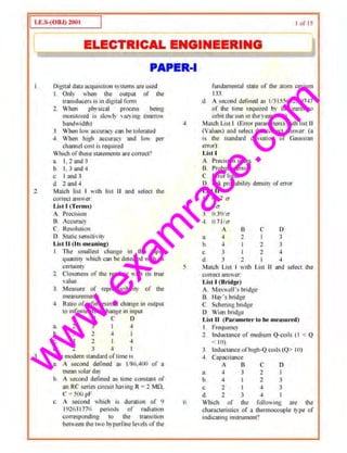
In the fcedba~k system C(s). R(s) and D(s)
an: the system oui]Jut. input and
disturbance. respectively
R(.) ~~JD(ool'--r-CI>l""
--@1>----'
Assertion (A): For the >ystem
C(s){ i?(.v) I D(s)j I• G(s)
R(.v)D(.v) I+G(,y)lf(s)
Reason (1{) : l'ransfer l'unctiun uf a system
is defined "-' the rntio of out]Jut Lap lace
transform and input Lap lace transform](https://image.slidesharecdn.com/ies-electrical-engineering-paper-1-2001-150815031919-lva1-app6891/85/Ies-electrical-engineering-paper-1-2001-6-320.jpg)

![w
w
w
.exam
race.com
84.
85.
87.
b. ± j0.5
c. Oand - l
d. 0.5 ± J0.5
Ir the NyquiSt pl01 curs Ihe negative real
u.xis uc u distance uf' 0..1, then Ute gain
tnargin 1)1't.hc system is
u. 0.4
b. - 0.4
c. 4UA
d..u
I he lrunsler functit>n of u phase lead
. . b l + al:!• I
compensator ts g:&'*Cn y - - w lere
J.;. Ts
a > I and I' > 0. The ma.ximwn phase shill
prowidcd by ;;uch a compensator is
a. tan ' ( tH· I')
a- 1
h. IJIJI '(''-I)a+ I
, -•( n + l)c.. sm - -
u- 1
d. siu-•(n- l)
a~ l
Consider the single inpu~ single output
~ystem with i~ stone vuriablo
roprc~ntation:
.l"=[~l -
0
2 ~]-"+[~]If0 0 - 3 0
Y=[l 0 2JX
The system is
u. Neither conlrolluble nor observable
b. Conlrollahle but nol observable
c. llncontrolloblc but observable
d. Both controllable and ob>~;ovabk
A l'ruticular control system is described by
lhe following state equations:
x=f0 1
]x-t[0
]u1lfld )'= [2 oJx-1 -3 I
Th~ lmnsfcr runction orIhis .-ystcm is:
l' (·') I
a.
U(s) 2s'+3N+l
r(s) 2
b. ~~.-"--
1!(<) 2.< o3s·• l
c l'(.>) I
· !' (s ) s1
+3s+2
nor 15
r(s) 2
d. ~.;----7--::-
C(s) s· +3.r+2
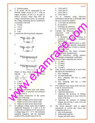
88. The mechanical ~ystem is ~!town in the
given figure
t--..:~a)--'QM~}L~F....liy,<•>
The system is describe<.! tl~
a M tl'.rl_[') + 8 dy,(1) = kfy. (1) - ,.,(:)]
dr dt - • •
b. ltcl'r,_(t) ~ edy,(l) =A[y (t) y,(1)}
dt' dt
c. .vd',t•,! I) + BdJ (I) - k(y1
(1)- y.(l)j
tlr d1 •
d. ..., ti'y,,!l) ~ n•(t,(I)= k[y,(:)- y. (tl]
.. . ' .
8/. /1. linear time invnrlam system. initially ai
rL'"'St wh"n ~ubjccled to a unit sicp input
guve response.t·(l) = te''(r ~ 0) .
The ttansfcr 1mction oftlle;yste.m is
a
(.v+ I)'
b. s(s+ l)'
I
c.
(s+ 1)'
I
d. (
S S+ l)
90. A >:·ncbro llunsmitlcr consisu; ol'u
t~ S><.Jicnt pol" rotor winding <.'..eltCd by
an lit supply und u Utrr:.:·phuso
nalanced smlor windins
b. f'hr~o~--phu.~e rn•lanl~ st•ror windio1g
excited by a three- phaS<.l halanccd ac
signal nnd rotor <'Onne<!led to u de
voltage source
c. Salient pole ro1or winding exdllxl by u
de signal
d. Cylindrical roror winding and o
stepped stalor e~~itcd by puis~
? 1. The torquc·speed clmractcristic .of rwo-
phuse induction motor is large!)' aiiected
hy
l~ Voltage
b. RIX and speed
c. X/ll
d. Supply voltage frequency
1)2. Match Li~l I (Nature of' cigcn value) with
Li>1 II (Nature l'f sfngulur point) for](https://image.slidesharecdn.com/ies-electrical-engineering-paper-1-2001-150815031919-lva1-app6891/85/Ies-electrical-engineering-paper-1-2001-12-320.jpg)
![w
w
w
.exam
race.com
93.
94.
95.
96.
llneariscd autonomous second order
systetn and select the correct answer:
List I
A.. Co1n111~x conjugate pair
B. Pure imaginary pair
C. Real and equal but with opposite sign
D. Real distinct and negarive
Lis1U
I. Centre
2. I'OCIIS poinl
3. Saddle point
4. Stable node
5. Unstable node
A B C D
a. 1 5 3 ~
~ 2 I 3 4
c. 2 I ~ 3
d. 1 5 4 3
In order to use Routll Hurwitz Criterion tor
dctennining the stability of sampled dara
•-vstcm. the chomctcristit! equation
I. r G(z) lltz) = 0 sbonld be moditied by
using bilinear u·ans fonn of
•· =: r+l
b. = ~r- 1
,._,
c. - -
- - r+l
r+l
d. ==---r- 1
The system matrix of n.discrete system is
~~! ~5]!'he characteristic equation is given by
a. z'+5z +3 - 0
b. z'-Jz- 5 =o
c. z'+3z + 5= O
d. Z.'+z+2 = 0
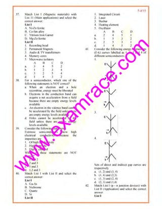
l11e current ln the giveLt drcuil with H
d"JlCndent voltage sourc.e is
..~
'L_____.J'"..a. lOA
b. 12A
c. 14 A
d. 161
!'he value of resistance ·R· shown in tho
givcn figure is
97.
98.
99.
IJ ortS
••
3 . 3.5Q
b. 2.50
c. 1!1
d. 4.50
An electric circuit w'ith 10 branches ami 7
nodes wiII haw
a. 3 IO!'P cquuti<~ns
b. 4 loop .:quations
c. 7 loop equations
d. I0 loop equations
Por the circuit shown in the given ligure.
the current thrOlmh L and the voltage
across~ arc respc~tively
a. zero and Rl
b. I and zero
c. zero and zero
d. land Rl
For the circuit shown in the. given ligurc.
when the vohagc.E is 10 V. the current Iis
I A. ll'tbc applied voltage across terminal
C-D is .I00 V, u.e short circuit CUri'CIIt
Oowing through the tennim!l A·B will be
a. II.IA
b. l A
c. lOA
d. IOOA
I00. The Thevenin's equivalent re~istance R,n
fur thegiwn nC>twOrk is
~'a_ IQ
b. 20
c. 40
d. lnlinily
101 , For the circuit 5hown in the given ligurc
the current I is given by](https://image.slidesharecdn.com/ies-electrical-engineering-paper-1-2001-150815031919-lva1-app6891/85/Ies-electrical-engineering-paper-1-2001-13-320.jpg)


This document contains a practice exam for an electrical engineering exam. It includes 35 multiple choice questions covering topics like digital data acquisition systems, electrical measurement instruments, bridges, transducers, and properties of materials. The questions test understanding of concepts like accuracy, resolution, error parameters, standards of time measurement, properties of thermistors, and characteristics of instruments like spectrum analyzers and digital meters.


![protection of transmission lines[distance relay protection scheme]](https://cdn.slidesharecdn.com/ss_thumbnails/os-exe3-23-may2011-sr-i-776s21tr-lineprotection-120425095503-phpapp02-thumbnail.jpg?width=640&height=640&fit=bounds)