Download to read offline
![w
w
w
.exam
race.com
15.
16.
17.
18.
19
2. Power flow d~nsily .........V 1l
3. Displaccrueut cUIT(JUl _ U!_ nou·
conducting mctlium ..... .. E If
Se]Qcl UJc- C<>l'I"CCI atl1WCf lliing the aode'
given below·
n, 1 t1lone
h. 2 3nd 3
o. I nntl3
tL I lllld 2
If tho dechic field E - U• I te' a, nnd €
; 4 '=" - U1cn the dl.~plnc.tment current
ero~ing ~~~ """' ofO. I ml atl ; 0 wtu be
a, 7.£m
" · 0.()4 "'"
c. 0.4 .;.
d. 4 ~.,
l'he directivity of11n .solropic antenna 1<
"· 7~
h. lcs~ than unity
c. unity
d. infonily
C'onsid~r the following ~1.11cmenb<:
l' or • uniform plane electromagnetic wave
I lhc direetion <11' energy flo" i• Ooe
Slime a. U1e direction of propugation of
U1e wat. V
2 electric •nd magnetic ficlds in time
qu.1dr.1ture.
3. electric and magnetic fields are in
space quadr31llrc.
Oflh""estatements
'~ 2 alone 1s com:d
h- l and 3·arecQrrecl
c t 3nd 2 are..:on·e.ct
tl. 3 nlonc is corr.:<:t
For"" •ir dielectric trnnsmiosion line. It i~
found that ~s lb<t frequtnC) is vorie(l from
SO Mflz upward, lloe current re~cloes •
minimum al 50-()1 Mtlz anti then a
muximum ~~ 50.04 -ZOiz Ute distone<; of
Uoc loc"tion of the ~lwrl-circuit from Ute
generotor will then I.e
a. Ill km
b. 2.5' kln
c.. I km
d. not dctet'minnblo fj·omlhc given dilln
Consider the following suotements;
PiezoelectJic materials :are usefi.tl t'or
converting
I. onechauical cner&)' into elecu ical
t>'UC18)'4
20.
21.
22.
23.
24.
~ ul I<
2. electrical <nergy into mechanical
energy.
J. mechanical energy inl.o chemical
energy.
4. chemical eui:rgy into mcch:~u icaL
energy.
Ofthese slat~ments
a. I and 2 are com;<:!
1!. l. 2. 3 and 4 ••·c correct
C. 1 alune is COITCCl
d. 2. 3 and ~ ore correct
Which one (lJ' llte followinl! c.~'lSSCS of
materials c.1n he categorised as rerrites'/
"· Plastics
b. Metals
c. AUO}"
d. Ceramics
C'onxider the fnllnwing in relutinn 1<1 the
orbilttl mot.inn nfan olectrr1n :
I. Slllteofenergy kwl
2 Orbillll angular momenwm
3. ,nglc between lhc applied magnetic
l'i"ld and angular mom<rulllm.
The quantum nnmben<. I, m ond n of nn
electron m orbit o·epo'<:senl respectively
a. I, 2 and 3
b. 2. 3 and I
c. 3, 2 and 1
d. 3. land 2
The oorrect ~equence Q!' Increasing order
of electrical resistivity of the given
lllatcrials t.
a. Dfumond. Uopcd gc'fltJonium, silicon,
_gold
b. Gold, $ilie<m. do1•ed germonium,
diamond
c. Gold. doped genuaruum_ silicon,
dillmood
d. Gold. dinnmnd. silicon, doped
germanlunt
F'<JI'mi 1~1 clos he
a. highest oeeupiod cmer!!)' Jovel at. 1.cro
kell~n
b. highest occupied energy !.::vel at II°C
c. energy level nt which electron
emi.ssiou occ:.uns
d. mmimum energy lcvd in the.
conduction bilnd
Wltich one of lhc tollowing statements I>'
correct'!
a. The absence ofa hyst~is loot>in J)lot
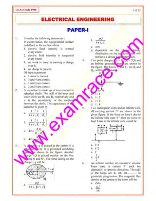
Ofpolnri.llltion ~gainst fidld is t>t-oof of](https://image.slidesharecdn.com/ies-electrical-engineering-paper-1-1998-150815031847-lva1-app6892/85/Ies-electrical-engineering-paper-1-1998-3-320.jpg)
![w
w
w
.exam
race.com
33.
]4.
35.
36.
8. 2 4 3
b. 4 2 3
c. 4 2 I 3
d. 1 .. 3
Luhiuru Noobme is ll~ed in
a SAW devices
b. LED's
c. dt~ manufacture ofopuca.l librcs
d. laser diodes
Mmch List-1 with List-11 and select tho
correct anser using the. codes given
bclo" the Lists :
Ust-1(,Jalnrill)
A. Paramagnetic
U. Diarnn,"Jlctie
l . Fcrromngnetic
D. i>errinmgnctic
List-II (.!Hgnclic susceptihility)
I. I()"'
2. 101
-10'
J. Hr'
4. 10-101
, B C 11
a 3 2 -1
h 3 4 2 I
~ I J 2 4
a 4 1 2 3
Which uf the followin[!. fs/are the
equivalent ~ircuil~ <If an imn-cored valid
at one frequency~
2
3
Select 1l1e correct answer usin~; the codes
giv~n be.low:
a. I alone
b. 2 alone
c. 2and3
d. I. 2and 3
A IOV buuery with un mternal resisumce
of I0. is connected across a oon-liocllf
load whose ''-i cha111Cto:ristic J$ given t>y
7i = v>+lv
l'he current del!vcrcd by 1hc bnnery is
a 2,5 A
b. 5A
c. 6A
d 7A
sur15
37. A vclltnge I· is applied to an ac circuit
resulting m the delivery or a current 1 •
Which or the lbllowing expressions would
yidll the true pO~er delivered b} ohe
source ·1
38.
39
40
1 Real pan of 11•
2. Real panori'i
,.3. f1 limes the real part of~
I
Select ohe eorrcct answer using the cod~$
gh'en below:
a I alone
b. I ;uod 3
c. land J
d. 3 alone
Mutch List-1 rl oop conl-epl) with l ist-11
(Junction concept) and selcd the correct
answer usmc the codes given below the
Lists:
Usr-1
A. Mesh
B. Outside mesh
C. Mesh curronl
D. Number ofmeshes
Lisi-11
I. Numb~r ofnodes
2. Node voltage
3 Rcrcrcncc nod<'
.J.. N(ldC
" 0 C D
3 . J .j 2
b. J 4 2 I
.:. 4 J 2 I
(I 4 l 2
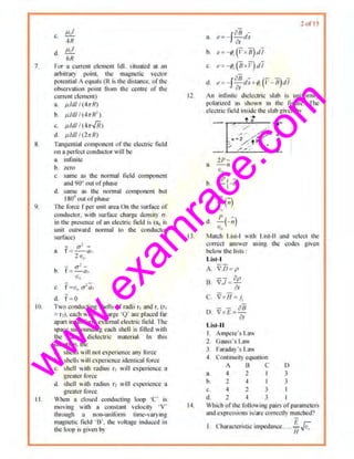
In the network shown in the ligure. ohe
eiTecoive re.•istanct fated b) !he voltngc
sotir<;t is
3. 40
b. 3n
c. U1
d 10
I'or the nerwor~ shown in t.hc fig1ore.. if V=
V1 and V = 0, Ihen = -5 A and ii' V = 0,
and V1 • t, then r • J/2 A. The values of](https://image.slidesharecdn.com/ies-electrical-engineering-paper-1-1998-150815031847-lva1-app6892/85/Ies-electrical-engineering-paper-1-1998-5-320.jpg)
![w
w
w
.exam
race.com
4 1.
-12.
43.
1._ and R1 or lhc Norton"s equivniL1ll
m;ross AB would he respc~tiwl) .
R.o~lh..e.
d:r.,;uh
a. -5 Aand20
h 10Anmi0.5Cl
"· 5 A nnd 2 n
d. l.SAnndHl
A I
A
J'he drlving-poilll impedance ofnone.-p<Jn
reoc1iw network is given by
a.
(h 1)(s1~2)
s(s' +3)(s' +4)
(.t''t l)(.•l+.1)
b
s(s' +l)(sl+4)
sV +I)
c. (i +2)(s' - 3)
I
<1. --
s+ l
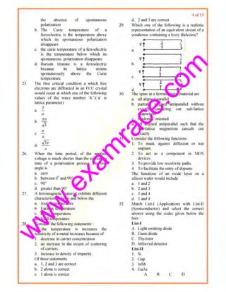
Ihe Thcvcnin cquivalcon of11n~t•vork is as
shown in the given figure For maximum
power transfer of th~ variable nnd purely
n.-sistive toad R1• it.~ resistance s/1ould be
a. 61) n
b. son
c.. 100n
d. inlinit)
lf l (I) • 114 (I- e 1
'1u (t) wh~re u (t) is o
unit step v!lltnge. then the complex
froqucncics associated with i (l) would
include
a. ;; = () nndj2
b. s = j2 ands ~ -jl
c.. s • -j2 and s • -2
d. s · O~nd s • -1
A 'T-nctwork is shown m the given Hgurc.
Its Y,. mau·ix will (units.in siemens)
"_ ....;;10;-:n ton
I • ~-- 2
rsnI,,,.,.__ _ ..)____ 7
45
46.
47
6 ul 15
a [;go 2~]5 10
200 2()()
b.[~~0 2~]- 5 10
200 200
c.. [~~~ 2~]
200 200
[
15 5 ]d. 200 200
5 ,,
200 200
The timc·cunslunlto the nctwml: ~h011 n in
the f.gurc i~
~~tla C'R
b. 2CR
c. CR/4
d. CRI2
For a two-port ne.tii·Urk ltl tit: r<~'iprocal . it
is n~:ccssnry thai
a. Z11 = Z.22 and Y!l ~ } 1:
b. Z11 : Zn and AD · BC s 0
c. lho= ·h ol andAD - Bc ~ o
d. Y21 ~ Y12and h2o=-h12
M:ltch Li.~I-1 (Parametors) with List-11
(Units) and solcc1 ~•c C(ltrecl answer using
the codes ~h·~n beh>w the lists:
Lis t-I
A. hu
B. hn
c. h1l
List-II
I. Dimensionless
2. Ohms
J. Siemens
A 0 c
a. I 2 3
b, J J 2
c. 2 I 3
d. J l I
4H. Two two-port networks mth tnmsoni.o;$ion
pornmetrrsA ~, B., Co. D,, and A ,. Ll:, C1.](https://image.slidesharecdn.com/ies-electrical-engineering-paper-1-1998-150815031847-lva1-app6892/85/Ies-electrical-engineering-paper-1-1998-6-320.jpg)
![w
w
w
.exam
race.com
49.
50.
51.
D1 respectl"ely are cascaded. The
trnnsmission paranteler matri~ of tho
t<JSC<tded network will he
8. [A, B.]-['1, 11, -J
C, D, C1 D,
b. [ 4 0.][·'- 8, -J
C, 01 c, D,
c. [A, il1 81 B, JC1 D, 0. D,
d [(A1A, +C1C,)( .~~, +B,D:J]
(c,A,-c,c,)(c,c,-o,o,)
An initially rdt~x~d RC-scrk~ nctwor~
II ith R~ 2Mfl Hlld C= Ij.IF is Slitched on
lu a I0 Y step input The 1·nltag~ across
lhc c.1pncitor nller 2 seconds will bt
11. Nro
b. 3,68 y
c. 6.32 y
d. 10 y
On eJiminatin!!c ihe feedback loop in the
sy>tcm sht11nin thu ligurc.
O T·1 • -
X, T,1 X,
it wotifd lead to a snnpHiicntion wllh R
srngle edge or~am
a 2iL.
I+T,
T~
b. ---
1- T,,
c. r.~
d. 2iL.
1- r,
For dte circuit shown in the given ligure. if
th~ input impednnce Z1 nt port I is givon
by
2
_ K,(s+2)
1 .' + 5
then the input im1~edance Z2 at port 2 will
be
'
~ ~
' (
_,--=3 '(.,
I a
a.
K,(.a3)
52.
53.
54.
b.
A'2 (s-1 2)
s +3
K .s
s+5
K,s
d.
s+ 2
7ol 15
)
.t+ 2
For Y(s = --'-'-"::-
5(s+ I)
the initial and timd
values ofv (l) will be rcspcctiwly
a I and I
b. 2 nnd ::l
c. 2nnd I
d. Imtdl
The net work funct ion
(s-"2)
F(s) = --'--~
(s+1)(.<+3)
rcprescms an
u. RC impedoncc
b. RL impcdoncc
c RC i111pcduncc and an Rl, admiunncc
d RC admittance and nn RL impedance
In the llf'tWr>rk s hCIIIIl in Fig I, if th~ IF
capacitor hnd, an initial I'Oitnge of 2Y.
then wltich of 01e following would
representthe s·domrun equt'alentcircuits?
r i(l)
•
•'Vts)
~Ai
~.I.
~--------------~'8 '
o·t•V (O)
2.
4.1' t
----------------'"18 ..
-+ l (o)
'
I' t•)
3.
-+ ((0)
0
+
v (1)
4. 8
Select tht! con'Ccl answer using the codl:l>
given below:
a. iUld J](https://image.slidesharecdn.com/ies-electrical-engineering-paper-1-1998-150815031847-lva1-app6892/85/Ies-electrical-engineering-paper-1-1998-7-320.jpg)

![w
w
w
.exam
race.com
77.
78.
79
80.
81,
82.
<J reduce struin on th~ main gauge
In a rwo-watuueter method of me~~Suriug
flOwer. one of !11~ wan- meters is reading
zcru wau,;. TI1c JlOIVl'r factor ortill' circuit
~~
a. Zcrv
h I
c. 0.5
d. o.s
Hall cllict device can be used 10
a. mulliply two signals
b divide one ~•gnal by anoth~~ 0 11 .an
insranumcous basis
<:, add two signnls
d subrrnct one signal from anmher
Match Ust-1 (Transdu~-erl willt List-11
(lnpui/Output varinbl.:s) and ~ kct the
correct aJt.~ller using the cocks given
hclow t11c Lists:
List-1
A, Elcclfodynamic gencrah•r
B. Venturimcter
C Pirani gauge
D. Sprmg hnlance
List-11
I. Gas pressure to resistance thw1g~
2. Force to displacclll:m
3. Motion to voiUij!c
4. f'low rruc ro pressure
A B C D
a 2 I ~ 3
h. 2 4 3
c. 3 4 2
d. J 4 2 I
Doppler shin princ-iple is uscu in the
measurl11l1Cnt of
a temperature
h frequency
c, S(>ccd
d pressure
lu di~tortoou factor meter, the ffilcr os used
to SUfJWO:SS
a deCMlf)OilCIIt
b udd homtonics
c. even hnrmonics
d. fund"meJltal~
Which ofthe following nlC<~sllrements call
he mode with the heir ol' a frequency
counter?
I Fundamental frequency ofInput signnl.
2 Fr~qucncy Gomponcnts of the input
signal ru least upto ohird harmonic.
83.
84.
K5.
86.
I!Juf l5
3 Time imerval between two pulses.
·L Pulse 'vidUt.
Select the currccL answer ltsiog the code;
given beluw:
a. I. 3 and 4
b. f, 2nnd3
c. '2 31id 4
cl I and2
Tbe bundwidlh requirement ol an FM
telemetry chawtel is
a eq~J!l] to that of an AM telemell')
Ghann,;f
b. smaller th~n ~1ot of an Am telemetry
churuoel
c. nbout IQ(J times that of 1111 AM
relemcll) channel
u. about ten tlm~ that of nn AM telemetry
channel
The r~cording l11:ad In a onagn~tic lapc
responds to
a. dectricnl ~'W"~ and c-reates u !llagncllc
signal
b. thc.rmul signal <md cre~tes a 011!,netic
signal
c. magnclic signal nnd creates an
clcctncal signal
d. thermal slgnalund creates an elcctricnl
signof
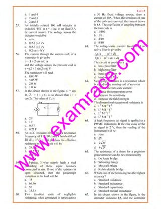
When tho ~ignal flow graph is as shown in
the tigure, the overall transfur function of
lhc sysr,,m will be
Qtl_·f-1, --·?~-----'1-il -H,
R
n. C =G
H
C G
b. li=1+ 11.
(' G
c. R= 77( ,-. -:-:H ,-:-) 77( , -.-:-:N ,~)
d
C G
H l+ ff,,. ff,
Ihe block diagram shown m fig. I is
equovalenl to
G ' c
lr,••---'
o I
a.
x:JX](https://image.slidesharecdn.com/ies-electrical-engineering-paper-1-1998-150815031847-lva1-app6892/85/Ies-electrical-engineering-paper-1-1998-10-320.jpg)

![w
w
w
.exam
race.com
92,
93.
94.
115.
Tlte open-loop transr~r fu•tctio•l ofu Ullity·
fc~dback comrol S)'stem is:
G(
K(s+ IO)(.r+20)
,l - •
s· t.v+2l
me closcd-lnt•p system will be stable if
the value ofK i<
.... 1
h J
c. 4
d. 5
Mntch Ust·l ( Piolldia~rnm/chan) with
List-11 (ChamcterisLiC) and select the
correct HliSIIer usi11g lhe lllldes given
bclo11 the lists :
l.ist-1
A. Consl!ml M loci
B. Cunsta111 N loci
C. Nichors chart
D. Nyquist plot
U st-11
I. Constom gain und pha.~ shill lod or
the closed- loop sysrem.
• Plot ofloop gain with variation of~~
J. Circles ofconsttmtgllin for closed loop
transfer function
.t CireiCc<~ uf constant pha:;.o: shifi of
closed - loop unnsfer runction
A B C ))
a, J 4 2 I
b. 3 4 2
c.
d.
3
3
2
I
L
2
l'he state and output equations ofo system
are as under state eqtllllOn:
[
,r, (t)J=[0 I][x, (t)]+[O]utn.~, (I) - 1 - 1 .t_, (I) I
Out:putcqumion :C(I) = (I 1][
1
' (I}]
x. (I)
l'hc syStem is
a. neither state comrollnblc nor output
controllable
b. stmc contrullabk hut not Ot!lput
comrollable
c. output conlttlllnble but nol stale
controllahlc
d. both state controllable and output
controllable
l'hc loop transfer funct•on Gil ofn control
system is gilen lly
96.
97,
98
I ~ uf 15
"Gil - -,--,-,..:"-'-:-:--:c-
,<(.t+ I)(,I I 2)(S I J)
Which oI' lhc followimt statements
reg;uding lhe conditions of the system root
loci diagram is/are C<lrrtct?
I TIIOI'(' will be fbur asymptotes
2 There will be three separate ron! lod
3 Asymptote.~ will 1mersect n1 realnxis 111
0~ =-l/3
Select the mrrect answer using lhe codes
givenbelow:
a I alone
b. 2 alone
c. 3 alone
d. 1.2and3
J'he value of A mntrix in X= AX lor lhe
system dcscnbcd by the diOcrtntiat
equation y +:!y +3)' = 0 is
a. r~2 ~,]
II. [~I ~~]
c. [~~ ~J
Q [~3 ~2]
The m1nimurn numller of '!ntcs necc.s.<nl)'
to describe ~1e network shown in the
ligurc in a state variable lbmt L'
a. 2
I> 3
c d
d. 6
Consider the follow•11g stalcmclltS
reg:u·dlng a linearsystem y~ 1XJ)
I. f(1<1 +x) = f(x, ) + f(.~!l
, f[~(t<- Tl ~ tlxttiJ- q xrrll
3. f(J.;.,x) = KP(x)
Oftllese statement~
a. I, 2 and 3 are correct
b. I and 2 arc.correct
c, 1 alone is correct](https://image.slidesharecdn.com/ies-electrical-engineering-paper-1-1998-150815031847-lva1-app6892/85/Ies-electrical-engineering-paper-1-1998-12-320.jpg)

![w
w
w
.exam
race.com
Reason (R) : The plot of a reactance
t(mction as a function of frcqt1cncy always
hns a positive slope.
a. Borh A and R are t:rue and R is the
correct explanation t,f A
b. Both J :tnd Rare true but R is NOT a
con·ect explanation of A
c, A is true but R is false
d. 1 is false bill R is true
11 4. Assertion (A) : The stcaJy-stat• response
<>f n linear network is ttnncd ' forced
response.
Icason (R) : I he foreing function dncs m)t
h11vc any dfcct on the tnmsknt re~ponsc
ofu Iinear system.
a. Both A and R are true and R is !he
etmect explanat·ion of A
b. Both 1 and Rare true but R is NOT a
correct explanation of A
c. 1 is true but R is false
d. A is fhlse but R is true
11 5. AsS<'rtion(A) : A ''ariancc. h dependent on
the mean value ofthe set ofdata.
Reason (R) : Variance (s !he difterencc of
the mean squared values nod the square of
!he mean value ofthe set of da~a.
a. Ooth A and R nro true and R is the
correct explanation ol' A
b. Both A and Rare true but R is NOT a
correc-t explanation of A
c. II i~ true but R is ful:;c
d. A is false but R is true
11 6. Assertion (A) : rhc vertical d<.'Oecting
plates of a CRT are kept 1;1rther away from
d'1< screeo as compar•d iCJ lho horizontal
dcOecting pl~tes.
11 7.
Reason (R) : This improves nccuracy in
n1eusurements.
a. l:loth A ~nJ R aro trUe and R is the
correct explanation ofA
b. Both A and Rare true but R is NO'I a
correct explanalion tJf 1
c. A is true but R is false
d. II is false but R. is true
TheNyquist plot ofa ~-ystem with the loup
transfer function G(s) H(s) is shown in !he
given figure :
1..
Assertion (A): The syst"in is unstable.
11 8.
I I'l.
15 ot 15
Reason (R) : The Nyquist lllot does not
encircle the criticalpoint (·I.jO).
a. Both A and R nre true nnd R is the
correct explanation ofA
b. Both A wtd Rare true hut R is N01 a
correct explanal'lon uf/
c. A is true bul R is false
d. A is false but R is true
Assertion (A) : When planl parameter
unccn:.1lnties arc present, tlte open-loop
structure is rotcnliillly supelior to the.
close<! loop stn1cture.
Reason (R) : When fecubnck is clliploycil,
there is n possibility ul' additional noi:«• or
uncertainty in the measurement of the
plant signals.
a. Both 1 and R are true nod R is the
correct e.xplaoation of A
b. l:loth A nnd Rare true but R is NO'I a
con ect explanat·ion ot' A
c. A is true but R is false
d. A is fals~ but R is true
Assenion (A) ; The compensn1ing netw(1rk
shown in t]k given figure is used for
(l!ducti()n of slt.'Udy-~utte errN in th._.
system respon~c.
-..!.·~·-.-~
It~ G
'· ct •·
ltcasoutR): A lead compensating network
reduces system steady-stnte error
;t. Ooth A aud R are true and R is til~
correct <!~plunati"n orII
b. Both A and Rare tn1e but R is NOT n
correct explanati011 orA
c. 1 is tn1e but R is lillse
d. A is false but R is true
t20. A smnpled d11tn system has !he li•lluwi11g
chnra<;tcristic equation in the r-plane
3.5r' -1.5r' ~ 0.5t'+ 2.5r = I)
=-1
wheror= --
! t I
Assertion (/) The system is uustable.
l~l.'asou (R) : Not uJI tho routs, or the
charaeterlstico equation f (7.) = 0 lie within
the uni1circle lzi = I itt the z · plane..
a. Bolh A and R arc true and R is th._.
correct explanation orA
h. Doth A wid Ran' true but R is NO'I u
cnm;ctcxplanatioll ut' II
c. 1 is 1ruc but R is lnlse
d. A i~ fulse but R is true](https://image.slidesharecdn.com/ies-electrical-engineering-paper-1-1998-150815031847-lva1-app6892/85/Ies-electrical-engineering-paper-1-1998-15-320.jpg)

This document contains a practice test for an electrical engineering exam. It includes 28 multiple choice questions covering various topics in electrostatics, circuit theory, electromagnetism, semiconductor physics, and materials. The questions involve concepts like electric fields, capacitance, magnetic fields, electromagnetic waves, energy bands in solids, ferromagnetism, and properties of materials like semiconductors, ferrites and ferroelectrics.


