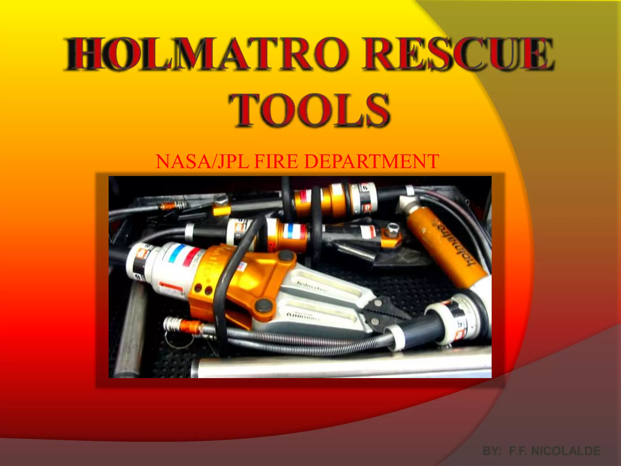
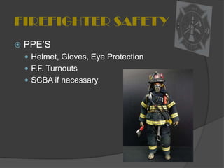
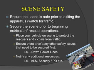
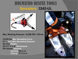
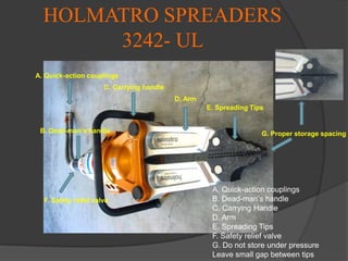
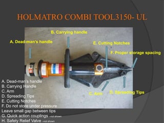
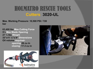
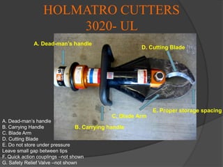
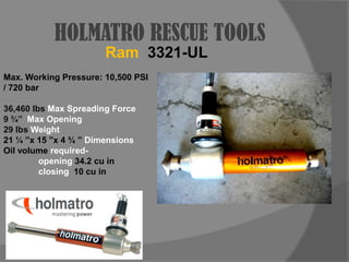
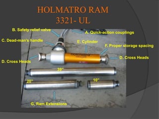
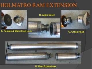
HOLMATRO RESCUE TOOLS NASA/JPLFIRE DEPARTMENTBY:  F.F. NICOLALDE
FIREFIGHTER SAFETYPPE’SHelmet, Gloves, Eye ProtectionF.F. TurnoutsSCBA if necessary
SCENE SAFETYEnsure the scene is safe prior to exiting the apparatus (watch for traffic).Secure the scene prior to beginning extrication/ rescue operations.Place your vehicle on scene to protect the rescuers and victims from traffic.Ensure there aren’t any other safety issues that need to be secured first. 		i.e.  -Down Power Lines Notify any additional resources.		i.e. : ALS, Security / PD etc.
ENGINE-1 RESCUE TOOLS
HOLMATRO RESCUE TOOLSSpreaders3242-ULMax. Working Pressure: 10,500 PSI / 720 bar19,595 lbs Max Spreading Force¼ inch Max Spreading Distance42.5 lbs Weight33”x11 ½”x 8” Dimensions Oil volume required- 		opening 26 cu in	closing  17.3 cu in
HOLMATRO SPREADERS 3242- UL A. Quick-action couplingsC. Carrying handleD. ArmE. Spreading TipsB. Dead-man’s handleG. Proper storage spacingA. Quick-action couplingsB. Dead-man’s handleC. Carrying HandleD. ArmE. Spreading TipsF. Safety relief valveG. Do not store under pressureLeave small gap between tipsF. Safety relief valve
HOLMATRO RESCUE TOOLSCombi Tool3150-ULMax. Working Pressure: 10,500 PSI / 720 bar67,600 lbs Max Cutting Force in Cutting Notch28,300 lbs Max Cutting Force in Central Cutter14 ¼ inch Max Spreading Distance35 lbs Weight33”x 9”x 7” Dimensions Oil volume required- 		opening 12.6 cu in		closing  16.8 cu in
HOLMATRO COMBI TOOL3150- UL B. Carrying handleA. Dead-man’s handleE. Cutting NotchesF. Proper storage spacingA. Dead-man’s handleB. Carrying HandleC. ArmD. Spreading TipsE. Cutting NotchesF. Do not store under pressureLeave small gap between tipsG. Quick action couplings –not shownH. Safety Relief Valve –not shownD. Spreading TipsC. Arm
HOLMATRO RESCUE TOOLSCutters3020-ULMax. Working Pressure: 10,500 PSI / 720 bar63,400 lbs Max Cutting Force5¼ Max Blade Opening27 ½ lbs Weight33”x11 ½”x 8” Dimensions Oil volume required- 		opening 26 cu in		closing  17.3 cu in
HOLMATRO CUTTERS 3020- UL A. Dead-man’s handleD. Cutting BladeE. Proper storage spacingC. Blade ArmA. Dead-man’s handleB. Carrying HandleC. Blade ArmD. Cutting BladeE. Do not store under pressureLeave small gap between tipsF. Quick action couplings –not shownG. Safety Relief Valve –not shownB. Carrying handle
HOLMATRO RESCUE TOOLSRam3321-ULMax. Working Pressure: 10,500 PSI / 720 bar36,460 lbs Max Spreading Force9 ¾” Max Opening29 lbs Weight21 ¼ ”x 15 ”x 4 ¾ ” Dimensions Oil volume required- 		opening 34.2 cu in		closing  10 cu in
HOLMATRO RAM3321- UL B. Safety relief valveA. Quick-action couplingsC. Dead-man’s handleE. CylinderF. Proper storage spacingD. Cross HeadsD. Cross Heads39” 10”20” G. Ram Extensions
HOLMATRO RAM EXTENSION B. Align NotchA. Female & Male Snap LockC. Cross Head D. Ram Extensions
HYDRAULIC HOSES100 FT LENGTH PRE-CONNECTED33 FT LENGTHPROPER USAGE1. Do Not Kink Hoses2. Do Not pull the hoses to move the tools.3. Prevent twisting of the hose4. Do Not use hoses to keep equipment in position. (especially if hoses are pressurized)
Hydraulic Hose Quick 	Connect CouplingsMaintenance Avoid allowing dirt inside of the couplings.
Remove dirt and oil with a clean dry rag.
Clean with mild soap and water.
You may Lubricate the coupling with hydraulic oil or by spraying WD-40.
Spray behind the locking sleeve and the back end of the coupling.  (Location A)Female couplingAMale CouplingLocking SleeveCoupling dust capsNOTE: After removing dust caps from the hydraulic hoses, make sure to secure the dust caps on the power unit by fastening them together around the frame. This keeps the dust caps from getting dirty and getting lost.
HOLMATRO ACCESSORY PULLING CHAINS Pulling attachment tips with hooksPulling chains: rated at chain strength grade 80, system 8, allowing a 2-1 safety working load with the rescue Holmatro tools. Material:Alloy steel, heat treatedPulling chains4.5 FT9 FT
HOLMATRO POWER UNIT2035 PHU E. Fuel CapD. Choke switchC. ExhaustB. Hydraulic oil dipstick   and FillF. Air filterG. Fuel ON/OFF SwitchA. Relief Valve with Connection CouplingH. Engine Switch ON/OFF          (Back Side)I. Starting CordJ. Speed SwitchK. Engine oil drain plugM. Hydraulic oil drain plug (underneath)L. Engine oil dipstick/filling nozzle (Back Side)
ENGINE-1 PORTABLE POWER UNIT OPERATIONSEnsure Proper PPE’s are worn during operation.Connect proper tool for rescue operations to the hydraulic hose found on the shelf above the hydraulic tools.Check fuel level, oil level, and hydraulic fluid levels, and ensure connections are secure.Ensure the Engine ON/OFF switch is in the On position.Ensure your fuel ON/OFF switch is in the On position.COLD START- ensure choke is in the On position and speed switch is on the fast position.Pull starting chord to start the engine.Once engine starts, turn off choke switch, and adjust engine speed.You are now ready to operate your Holmatro Tool.Turn the Operating Relief Valve to the Operation position.H. Engine Switch ON/OFF
HOLMATRO POWER UNIT2035 PHU  (continued)L. Engine oil dipstick/filling nozzleA. Relief Valve with Connection CouplingHONDA  4 stroke engine 2.5 HPI. Starting CordJ. Speed Switch
ENGINE-1 FIXED POWER UNIT OPERATIONSEngine-1 Master Turn on Engine, and Power to the GEN/PTO inside the Engine Cab. Follow Steps A,B,CTurn on breaker main and corresponding breakers.Ensure Proper PPE’s are worn during operation.A. Turn Ignition switch to the ON position.B. Press Engine Start Toggle switchC. Turn On GEN. PTO Toggle switch

Holmatro Rescue Tools

  • 1.
    HOLMATRO RESCUE TOOLSNASA/JPLFIRE DEPARTMENTBY: F.F. NICOLALDE
  • 2.
    FIREFIGHTER SAFETYPPE’SHelmet, Gloves,Eye ProtectionF.F. TurnoutsSCBA if necessary
  • 3.
    SCENE SAFETYEnsure thescene is safe prior to exiting the apparatus (watch for traffic).Secure the scene prior to beginning extrication/ rescue operations.Place your vehicle on scene to protect the rescuers and victims from traffic.Ensure there aren’t any other safety issues that need to be secured first. i.e. -Down Power Lines Notify any additional resources. i.e. : ALS, Security / PD etc.
  • 4.
  • 5.
    HOLMATRO RESCUE TOOLSSpreaders3242-ULMax.Working Pressure: 10,500 PSI / 720 bar19,595 lbs Max Spreading Force¼ inch Max Spreading Distance42.5 lbs Weight33”x11 ½”x 8” Dimensions Oil volume required- opening 26 cu in closing 17.3 cu in
  • 6.
    HOLMATRO SPREADERS 3242-UL A. Quick-action couplingsC. Carrying handleD. ArmE. Spreading TipsB. Dead-man’s handleG. Proper storage spacingA. Quick-action couplingsB. Dead-man’s handleC. Carrying HandleD. ArmE. Spreading TipsF. Safety relief valveG. Do not store under pressureLeave small gap between tipsF. Safety relief valve
  • 7.
    HOLMATRO RESCUE TOOLSCombiTool3150-ULMax. Working Pressure: 10,500 PSI / 720 bar67,600 lbs Max Cutting Force in Cutting Notch28,300 lbs Max Cutting Force in Central Cutter14 ¼ inch Max Spreading Distance35 lbs Weight33”x 9”x 7” Dimensions Oil volume required- opening 12.6 cu in closing 16.8 cu in
  • 8.
    HOLMATRO COMBI TOOL3150-UL B. Carrying handleA. Dead-man’s handleE. Cutting NotchesF. Proper storage spacingA. Dead-man’s handleB. Carrying HandleC. ArmD. Spreading TipsE. Cutting NotchesF. Do not store under pressureLeave small gap between tipsG. Quick action couplings –not shownH. Safety Relief Valve –not shownD. Spreading TipsC. Arm
  • 9.
    HOLMATRO RESCUE TOOLSCutters3020-ULMax.Working Pressure: 10,500 PSI / 720 bar63,400 lbs Max Cutting Force5¼ Max Blade Opening27 ½ lbs Weight33”x11 ½”x 8” Dimensions Oil volume required- opening 26 cu in closing 17.3 cu in
  • 10.
    HOLMATRO CUTTERS 3020-UL A. Dead-man’s handleD. Cutting BladeE. Proper storage spacingC. Blade ArmA. Dead-man’s handleB. Carrying HandleC. Blade ArmD. Cutting BladeE. Do not store under pressureLeave small gap between tipsF. Quick action couplings –not shownG. Safety Relief Valve –not shownB. Carrying handle
  • 11.
    HOLMATRO RESCUE TOOLSRam3321-ULMax.Working Pressure: 10,500 PSI / 720 bar36,460 lbs Max Spreading Force9 ¾” Max Opening29 lbs Weight21 ¼ ”x 15 ”x 4 ¾ ” Dimensions Oil volume required- opening 34.2 cu in closing 10 cu in
  • 12.
    HOLMATRO RAM3321- ULB. Safety relief valveA. Quick-action couplingsC. Dead-man’s handleE. CylinderF. Proper storage spacingD. Cross HeadsD. Cross Heads39” 10”20” G. Ram Extensions
  • 13.
    HOLMATRO RAM EXTENSIONB. Align NotchA. Female & Male Snap LockC. Cross Head D. Ram Extensions
  • 14.
    HYDRAULIC HOSES100 FTLENGTH PRE-CONNECTED33 FT LENGTHPROPER USAGE1. Do Not Kink Hoses2. Do Not pull the hoses to move the tools.3. Prevent twisting of the hose4. Do Not use hoses to keep equipment in position. (especially if hoses are pressurized)
  • 15.
    Hydraulic Hose Quick Connect CouplingsMaintenance Avoid allowing dirt inside of the couplings.
  • 16.
    Remove dirt andoil with a clean dry rag.
  • 17.
    Clean with mildsoap and water.
  • 18.
    You may Lubricatethe coupling with hydraulic oil or by spraying WD-40.
  • 19.
    Spray behind thelocking sleeve and the back end of the coupling. (Location A)Female couplingAMale CouplingLocking SleeveCoupling dust capsNOTE: After removing dust caps from the hydraulic hoses, make sure to secure the dust caps on the power unit by fastening them together around the frame. This keeps the dust caps from getting dirty and getting lost.
  • 20.
    HOLMATRO ACCESSORY PULLINGCHAINS Pulling attachment tips with hooksPulling chains: rated at chain strength grade 80, system 8, allowing a 2-1 safety working load with the rescue Holmatro tools. Material:Alloy steel, heat treatedPulling chains4.5 FT9 FT
  • 21.
    HOLMATRO POWER UNIT2035PHU E. Fuel CapD. Choke switchC. ExhaustB. Hydraulic oil dipstick and FillF. Air filterG. Fuel ON/OFF SwitchA. Relief Valve with Connection CouplingH. Engine Switch ON/OFF (Back Side)I. Starting CordJ. Speed SwitchK. Engine oil drain plugM. Hydraulic oil drain plug (underneath)L. Engine oil dipstick/filling nozzle (Back Side)
  • 22.
    ENGINE-1 PORTABLE POWERUNIT OPERATIONSEnsure Proper PPE’s are worn during operation.Connect proper tool for rescue operations to the hydraulic hose found on the shelf above the hydraulic tools.Check fuel level, oil level, and hydraulic fluid levels, and ensure connections are secure.Ensure the Engine ON/OFF switch is in the On position.Ensure your fuel ON/OFF switch is in the On position.COLD START- ensure choke is in the On position and speed switch is on the fast position.Pull starting chord to start the engine.Once engine starts, turn off choke switch, and adjust engine speed.You are now ready to operate your Holmatro Tool.Turn the Operating Relief Valve to the Operation position.H. Engine Switch ON/OFF
  • 23.
    HOLMATRO POWER UNIT2035PHU (continued)L. Engine oil dipstick/filling nozzleA. Relief Valve with Connection CouplingHONDA 4 stroke engine 2.5 HPI. Starting CordJ. Speed Switch
  • 24.
    ENGINE-1 FIXED POWERUNIT OPERATIONSEngine-1 Master Turn on Engine, and Power to the GEN/PTO inside the Engine Cab. Follow Steps A,B,CTurn on breaker main and corresponding breakers.Ensure Proper PPE’s are worn during operation.A. Turn Ignition switch to the ON position.B. Press Engine Start Toggle switchC. Turn On GEN. PTO Toggle switch