The document discusses a self-reconfigurable robot module called Hinged-Tetro that can transform itself into the seven Tetris piece shapes (tetrominoes). Hinged-Tetro uses the principle of hinged dissection of polyominoes, which are plane geometric shapes composed of joined squares. It can change its own structure through intra-reconfiguration and combine with other identical modules for inter-reconfiguration, making it suitable for studying nested reconfiguration in modular robots. Preliminary experiments demonstrate the robot's ability to reconfigure itself between the seven tetrominoes shapes.
![Hinged-Tetro: A Self-reconfigurable Module for Nested Reconfiguration
Vincent Kee, Nicolas Rojas, Mohan Rajesh Elara, and Ricardo Sosa
Abstract— Nested reconfiguration is an emerging research
area in modular robotics. Such a novel design concept utilizes
individual robots with distinctive reconfiguration characteristics
(intra-reconfigurability) capable of combining with other ho-
mogeneous/heterogeneous robots (inter-reconfigurability). The
objective of this approach is to generate more complex mor-
phologies for performing specific tasks that are far from the
capabilities of a single module or to respond to programmable
assembly requirements. The two-level reconfiguration process
in nested reconfigurable robotic system implies several technical
challenges in hardware design, planning algorithms, and control
strategies. In this paper, we discuss the theory, concept, and
initial mechanical design of Hinged-Tetro, a self-reconfigurable
module conceived for the study of nested reconfiguration.
Hinged-Tetro is a mobile robot that uses the principle of
hinged dissection of polyominoes to transform itself into any
of the seven one-sided tetrominoes, the Tetris pieces, in a
straightforward way. The robot can also combine with other
modules for shaping complex structures or giving rise to a robot
with new capabilities. Some preliminary experiments of intra-
reconfigurability with an implemented prototype are presented.
I. INTRODUCTION
Reconfigurability is a valuable design strategy in robotics
that has been studied since the 1980s. It typically falls
into two broad classes: intra-reconfigurability and inter-
reconfigurability. An intra-reconfigurable robot can be
viewed as a collection of components (sensors, actuators,
mechanical parts, power sources, controllers, etc.) acting
as a single entity while having the ability to change, for
instance, its structure, mobility, or principal activity without
requiring any external assembly or disassembly. In contrast,
an inter-reconfigurable robot consists of a congregation of
modular homogenous or heterogeneous components capable
of forming a variety of morphologies through an ongoing
attachment and detachment process.
Intra-reconfigurability has been generally centered on
functional modules, namely motion, sensing, and control.
Intra-reconfiguration for motion allows robots the flexibility
of traversing over a variety of terrains and spaces (land,
air, and water) as well as a series of manipulation skills.
Vincent Kee is with the Electrical Engineering and Computer Science
Department, Massachusetts Institute of Technology, 77 Massachusetts Ave,
Cambridge, MA 02139 (email: vkee@mit.edu)
Nicolas Rojas was with the SUTD-MIT International Design Center,
Singapore University of Technology and Design. He is now with the De-
partment of Mechanical Engineering and Materials Science, Yale University,
New Haven, CT, USA (email: nicolas.rojas@yale.edu)
Mohan Rajesh Elara and Ricardo Sosa are with the Engineering
Product Development Pillar, Singapore University of Technology and
Design, 20 Dover Drive Singapore 138682 (email: {rajeshelara, ri-
cardo sosa}@sutd.edu.sg).
This work was supported by the SUTD-MIT International Design Center
under grants IDG31200110 and IDD41200105.
Examples include versatile amphibious robots capable of
intra-reconfiguration between terrestrial and aquatic gait
mechanisms [1], metamorphic robotic hands capable of intra-
reconfigurable palm topologies [2], and reconfigurable walk-
ing mechanisms that produce a wide variety of gait cycles
[3]. Intra-reconfiguration for sensing enables a robot to adapt
its sensor configuration to the environment or task at hand.
To this end, evolutionary design techniques for perceptual
intra-reconfigurability [4], [5] and strategies for recognizing
and eliminating corrupted sensory have been proposed [6].
Finally, intra-reconfiguration for computing allows robots
to reconfigure its control in response to environmental/task
demands [7], [8], [9].
Inter-reconfigurability has gained widespread popularity in
the robotics community due to the possibility of assembling
a variety of specialized robots and complex structures using a
standard set of components. Numerous inter-reconfigurable
robots have been developed for a variety of potential ap-
plications ranging from surveillance to space exploration
and using different schemes for module docking and un-
docking, and all types of reconfiguration —manual, semi-
manual, and self. Relevant examples include CEBOT, Poly-
Bot, Crystalline, M-TRAN, ATRON, Molecube, CKBot, and
many others. For a complete review of inter-reconfigurable
robotics, its history, concept, and most important results, the
interested reader is referred to [10], [11], [12].
Given this picture of the reconfigurable robotics field, we
consider the next step in the area is to integrate the advan-
tages of the intra-reconfigurability and inter-reconfigurability
concepts. We call this consolidated approach: nested recon-
figuration. A nested reconfigurable robotic system can be
defined as a set of modular robots with individual reconfig-
uration characteristics (intra-reconfigurability) that combine
with other homogeneous/heterogeneous robot modules (inter-
reconfigurability). The objective of this system is to generate
more complex morphologies for performing specific tasks
that are far from the capabilities of a single unit or to respond
to programmable assembly requirements.
The distinction between intra- and inter-reconfigurability
has been framed previously as assembly and disassembly
at macro- and micro- scales, wherein the individual robotic
module maintains its morphology as constant when assem-
bled in an aggregate structure [13]. The concept of nested
reconfiguration explicitly considers the ability of the modular
components at the atomic level to internally transform their
morphology without splitting. This can be seen in fact as
a generalization of the self-deformation principle used in
tensegrity-based cellular robots [14].
In this paper, we discuss the theory, concept, and initial
2014 IEEE/ASME International Conference on
Advanced Intelligent Mechatronics (AIM)
Besançon, France, July 8-11, 2014
978-1-4799-5736-1/14/$31.00 ©2014 IEEE 1539](https://image.slidesharecdn.com/afcc568c-ba77-4f76-829a-184f0d6345da-160713012612/85/hinged_tetro-1-320.jpg)
![Hinged-Tetro: A Self-reconfigurable Module for Nested Reconfiguration
Vincent Kee, Nicolas Rojas, Mohan Rajesh Elara, and Ricardo Sosa
Abstract— Nested reconfiguration is an emerging research
area in modular robotics. Such a novel design concept utilizes
individual robots with distinctive reconfiguration characteristics
(intra-reconfigurability) capable of combining with other ho-
mogeneous/heterogeneous robots (inter-reconfigurability). The
objective of this approach is to generate more complex mor-
phologies for performing specific tasks that are far from the
capabilities of a single module or to respond to programmable
assembly requirements. The two-level reconfiguration process
in nested reconfigurable robotic system implies several technical
challenges in hardware design, planning algorithms, and control
strategies. In this paper, we discuss the theory, concept, and
initial mechanical design of Hinged-Tetro, a self-reconfigurable
module conceived for the study of nested reconfiguration.
Hinged-Tetro is a mobile robot that uses the principle of
hinged dissection of polyominoes to transform itself into any
of the seven one-sided tetrominoes, the Tetris pieces, in a
straightforward way. The robot can also combine with other
modules for shaping complex structures or giving rise to a robot
with new capabilities. Some preliminary experiments of intra-
reconfigurability with an implemented prototype are presented.
I. INTRODUCTION
Reconfigurability is a valuable design strategy in robotics
that has been studied since the 1980s. It typically falls
into two broad classes: intra-reconfigurability and inter-
reconfigurability. An intra-reconfigurable robot can be
viewed as a collection of components (sensors, actuators,
mechanical parts, power sources, controllers, etc.) acting
as a single entity while having the ability to change, for
instance, its structure, mobility, or principal activity without
requiring any external assembly or disassembly. In contrast,
an inter-reconfigurable robot consists of a congregation of
modular homogenous or heterogeneous components capable
of forming a variety of morphologies through an ongoing
attachment and detachment process.
Intra-reconfigurability has been generally centered on
functional modules, namely motion, sensing, and control.
Intra-reconfiguration for motion allows robots the flexibility
of traversing over a variety of terrains and spaces (land,
air, and water) as well as a series of manipulation skills.
Vincent Kee is with the Electrical Engineering and Computer Science
Department, Massachusetts Institute of Technology, 77 Massachusetts Ave,
Cambridge, MA 02139 (email: vkee@mit.edu)
Nicolas Rojas was with the SUTD-MIT International Design Center,
Singapore University of Technology and Design. He is now with the De-
partment of Mechanical Engineering and Materials Science, Yale University,
New Haven, CT, USA (email: nicolas.rojas@yale.edu)
Mohan Rajesh Elara and Ricardo Sosa are with the Engineering
Product Development Pillar, Singapore University of Technology and
Design, 20 Dover Drive Singapore 138682 (email: {rajeshelara, ri-
cardo sosa}@sutd.edu.sg).
This work was supported by the SUTD-MIT International Design Center
under grants IDG31200110 and IDD41200105.
Examples include versatile amphibious robots capable of
intra-reconfiguration between terrestrial and aquatic gait
mechanisms [1], metamorphic robotic hands capable of intra-
reconfigurable palm topologies [2], and reconfigurable walk-
ing mechanisms that produce a wide variety of gait cycles
[3]. Intra-reconfiguration for sensing enables a robot to adapt
its sensor configuration to the environment or task at hand.
To this end, evolutionary design techniques for perceptual
intra-reconfigurability [4], [5] and strategies for recognizing
and eliminating corrupted sensory have been proposed [6].
Finally, intra-reconfiguration for computing allows robots
to reconfigure its control in response to environmental/task
demands [7], [8], [9].
Inter-reconfigurability has gained widespread popularity in
the robotics community due to the possibility of assembling
a variety of specialized robots and complex structures using a
standard set of components. Numerous inter-reconfigurable
robots have been developed for a variety of potential ap-
plications ranging from surveillance to space exploration
and using different schemes for module docking and un-
docking, and all types of reconfiguration —manual, semi-
manual, and self. Relevant examples include CEBOT, Poly-
Bot, Crystalline, M-TRAN, ATRON, Molecube, CKBot, and
many others. For a complete review of inter-reconfigurable
robotics, its history, concept, and most important results, the
interested reader is referred to [10], [11], [12].
Given this picture of the reconfigurable robotics field, we
consider the next step in the area is to integrate the advan-
tages of the intra-reconfigurability and inter-reconfigurability
concepts. We call this consolidated approach: nested recon-
figuration. A nested reconfigurable robotic system can be
defined as a set of modular robots with individual reconfig-
uration characteristics (intra-reconfigurability) that combine
with other homogeneous/heterogeneous robot modules (inter-
reconfigurability). The objective of this system is to generate
more complex morphologies for performing specific tasks
that are far from the capabilities of a single unit or to respond
to programmable assembly requirements.
The distinction between intra- and inter-reconfigurability
has been framed previously as assembly and disassembly
at macro- and micro- scales, wherein the individual robotic
module maintains its morphology as constant when assem-
bled in an aggregate structure [13]. The concept of nested
reconfiguration explicitly considers the ability of the modular
components at the atomic level to internally transform their
morphology without splitting. This can be seen in fact as
a generalization of the self-deformation principle used in
tensegrity-based cellular robots [14].
In this paper, we discuss the theory, concept, and initial
2014 IEEE/ASME International Conference on
Advanced Intelligent Mechatronics (AIM)
Besançon, France, July 8-11, 2014
978-1-4799-5736-1/14/$31.00 ©2014 IEEE 1539](https://image.slidesharecdn.com/afcc568c-ba77-4f76-829a-184f0d6345da-160713012612/75/hinged_tetro-1-2048.jpg)
![(a)
(b)
I
O
T
S
Z
L
J
Fig. 1. (a): An example of a polyonimo composed of 16 squares —
i.e., a 16-omino (top). A set of joined squares that is not a polyomino. In
general, shapes formed by at least one couple of squares connected only
at their corners are not considered polyominoes (bottom-left). The first
polyomino with a hole, an heptomino (bottom-right). (b): The seven one-
sided tetrominoes and their corresponding names.
mechanical design of Hinged-Tetro, a self-reconfigurable
module conceived for the study of nested reconfiguration.
Hinged-Tetro is a mobile self-reconfigurable robot module
based on the theory of hinged dissection of polyominoes that
is able to transform itself into any of the one-sided tetromi-
noes, the Tetris pieces. The robot is of interest for research
in nested reconfiguration because it can easily change its
structure and also combine with other modules to form new
morphologies to accomplish, for instance, manipulation tasks
that a single robot could not handle on its own.
The rest of this paper is organized as follows. Section II
introduces the concept of polyominoes with some historical
considerations and important results. Section III presents
the idea of hinged dissections of polyominoes, where some
statements of relevance for the design of Hinged-Tetro are
discussed and proven. Section IV focuses on the mechanical
design of the proposed robot module. Some preliminary
experiments of intra-reconfiguration operations with an im-
plemented prototype are shown in section V. Finally, section
VI concludes the paper and discusses future work.
II. POLYOMINOES
Polyominoes, sometimes called n-ominoes or super-
dominoes, are plane geometric figures formed by joining one
or more equal squares (cells) edge to edge. An example of a
polyomino, a 16-omino, is presented in Fig. 1(a: top). Since
its perimeter (24 units) is not equal to that of its minimal
bounding box (20 units), this shape corresponds to a non-
convex polyomino. Sets of joined squares with at least one
couple of cells connected only at their corners [Fig. 1(a:
bottom-left)] or with edges that do not perfectly match to
each other, are not considered polyominoes. Observe that
polyomino regions may be hollow, the first polyomino with
a hole is the heptomino depicted in Fig. 1(a: bottom-right)
—a polyomino of seven squares.
Polyominoes can be seen as a generalization of the domino
—the two equal squares joined edge to edge used in the
eponymous board game— to a set of multiple squares. The
word polyomino is attributed to Solomon Golomb [15], [16];
who seems to be the first mathematician to treat the subject
seriously, a passion that started during his graduate studies
in Harvard [17]. Polyominoes are familiar in popular culture
because they have been used as entertainment puzzles since,
at least, the eighteenth century. Classical examples of such
practical assembly games include the rectangular puzzles
Jags and Hooks (1785) and Sectional Checkerboard (1880)
[18].
Since the 1950s, several authors have discussed the prob-
lem of estimating the number t(n) of polyominoes composed
of n squares [17]. Currently, the best known bound is
3.9856n
< t(n) < 4.6496n
[19]. This counting considers
fixed polyominoes, known as lattice animals in statistical
physics. In such polyominoes only translation movements
are assumed, so two fixed polyominoes are different if they
do not have the same orientation. Polyominoes that can be
translated and rotated but not reflected are called one-sided
polyominoes. Those that can be picked up and flipped are
called free polyominoes. The number of free n-ominoes,
say r(n), is less than or equal to the number of one-sided
n-ominoes, say s(n). In fact, it can be easily shown that
t(n)
8 ≤ r(n) ≤ s(n) ≤ t(n) [20]. For instance, there
are one free, one one-sided, and two fixed dominoes (2-
ominoes), two free, two one-sided, and six fixed triominoes
(3-ominoes), and five free, seven one-sided, and nineteen
fixed tetrominoes (4-ominoes). Table I shows the number
of the three kind of polyominoes of up to 8 squares [20].
In this work, we present a self-reconfigurable robot mod-
ule able to transform itself into any of the seven one-
sided tetrominoes, depicted in Fig. 1(b), for the fundamental
study of nested reconfigurable robotic systems. Tetrominoes,
popular for their use in the video game Tetris and common
in tiling problems —see, for instance, [21], have also been
used as models for the better understanding of self-assembly
processes in small molecules and nanoparticles [22].
III. HINGED DISSECTIONS OF POLYOMINOES
A dissection of a geometric figure cuts it into a finite
number of smaller pieces that can be rearranged to form
1540](https://image.slidesharecdn.com/afcc568c-ba77-4f76-829a-184f0d6345da-160713012612/85/hinged_tetro-2-320.jpg)
![TABLE I
THE NUMBER OF n-OMINOES FOR n ≤ 8
Name n Free
One-
sided
Fixed
Monomino 1 1 1 1
Domino 2 1 1 2
Triomino 3 2 2 6
Tetromino 4 5 7 19
Pentomino 5 12 18 63
Hexomino 6 35 60 216
Heptomino 7 108 196 760
Octomino 8 369 704 2725
another figure [23], [24]. For example, any two simple
polygons in the plane —i.e., polygons with non-intersecting
sides— of equal area can be dissected by straight line cuts
into a finite number of congruent polygonal figures which
can be rearranged without overlapping to form the other
polygon [25], a result known as the Wallace-Bolyai-Gerwien
theorem [26]. Some popular geometric dissections include
the Tangram —the dissection puzzle invented in ancient
China, the Hindu problem —the Greek cross dissection into
five pieces to form a square [27], and the Bhaskara’s proof
of the Pythagorean theorem [28].
Now, let us suppose that instead of allowing the smaller
figures in a dissection to be rearranged arbitrarily, the pieces
are pin-jointed at their vertices. This special subclass of
dissections are called hinged dissections [29]. In 1864, the
British mathematician and physicist Phillip Kelland pre-
sented what seems to be the first published hinged dissection
[24], a proof by rearrangement of the Pythagorean theorem
[Fig. 2(top)]. For many years, a problem that aroused the
interest of several mathematicians was determining if there
is always a hinged dissection between two simple polygons,
that is, if there exists a collection of geometric shapes
hinged at their vertices that can be folded in the plane
continuously without self-intersection to form both polygons.
Fig. 2(bottom) shows a classical example of this problem,
the hinged dissection of an equilateral triangle into a square
by Henry Dudeney [30]; see [29]. Recently, in a remarkable
work, Abbott et al. [31] generalized the hinged dissection
problem of two polygons and constructively proved that
actually any finite collection of polygons of equal area
has a common hinged dissection. The following theorem
summarizes this result:
Theorem 1 (Abbott et al., 2012) Any finite set of polygons
of equal area have a common hinged dissection that can fold
continuously without intersection between the polygons. For
two target polygons with vertices drawn on a rational grid,
the number of required pieces is pseudopolynomial, as is the
running time of the algorithm to compute the common hinged
dissection.
Since any polyomino can be associated to a polygon —
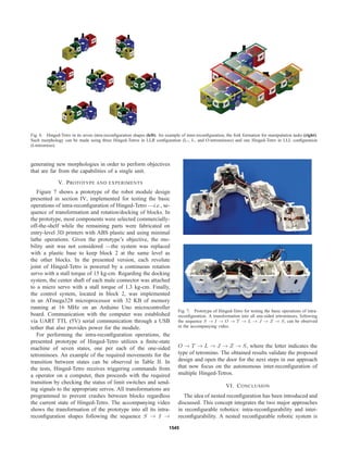
Fig. 2. Examples of hinged dissections. Kelland’s proof of the Pythagorean
theorem by a hinged rearrangement (top). Dudeney’s hinged dissection of
an equilateral triangle into a square (bottom).
in the case of tetrominoes, for instance, I corresponds to a
rectangle, O to a square, and T to an octagon, theorem 1
implies that there exists at least one hinged dissection of
polygons that can be rotated into any n-omino for a given
n. In fact, in [29], the authors propose an elegant hinged
dissection of polyominoes and prove that:
Theorem 2 (Demaine et al., 2005) A cycle of 2 n right
isosceles triangles, joined at their base vertices, can be
rotated into any n-omino.
Although theorem 2 gives us the appropriate foundation to
develop a self-reconfigurable robot module able to transform
itself into any of the seven one-sided tetrominoes; for me-
chanical simplicity reasons (e.g. number of joints, process of
transformation), we are interested in the natural hinged dis-
sections of polyominoes. A natural dissection is the cutting of
a n-omino into some of its constituent squares. When all of
them are cut using n−1 hinges, the corresponding dissection
is called a maximum natural dissection. An example of a
non-maximum natural dissection of polyominoes is depicted
in Fig. 3(a: left). In this instance, three stacked identical
squares dissected by only one hinge can be rotated into the
two one-side triominoes [Fig. 3(a: right)]. Such dissection is
called the L-hinged dissection of triominoes —the L stands
for the position on the hinge from a top view of the three
stacked identical squares. For the case of tetrominoes, a
possible option of maximum natural dissection is the LRL-
hinged dissection presented in Fig. 3(b: right). However, all
the one-side tetrominoes cannot be obtained by rotations of
this hinged dissection:
Lemma 3 The LRL-hinged dissection of four identical
squares cannot be rotated into all one-sided tetrominoes.
Proof: First, according to the notation of Fig. 3(b:
right), let us consider some unfeasible relative locations of
squares 1 and 3. For example, given that the hinges joining
them to square 2 are in opposite corners, it is not possible
that square 1 and 3 share an edge after a rotation, of both
or one of them, respect to square 2. In general, if we trace
1541](https://image.slidesharecdn.com/afcc568c-ba77-4f76-829a-184f0d6345da-160713012612/85/hinged_tetro-3-320.jpg)
![(a)
(b)
1
11
111
2
2
2
222
3
3
3
333
444
Fig. 3. (a): The L-hinged dissection of three stacked identical squares
(left) can be rotated into the two one-side triominoes (right). The dark
gray indicates that square 1 is rotated (+180◦) respect to square 2 in
order to obtain the second triomino. (b): Maximum natural dissections of
tetrominoes. The LLL-hinged dissection (left), the LLR-hinged dissection
(center), and the LRL-hinged dissection (right). The LRL-hinged dissection
cannot be rotated into all one-sided tetrominoes (Lemma 3).
two lines —one vertical and another horizontal— dividing
square 2 into four equal parts and splitting the Euclidean
plane into six regions (including the lines itself), there is no
option that after any combination of rotations, squares 1 and
3 lie at consecutive regions.
Now, suppose that the LRL-hinged dissection can be ro-
tated into the T-tetromino [Fig. 1(b)]. Since for any tetromino
there are 24 different ways of labeling the constituent squares
using the set {1, 2, 3, 4}, this implies that at least one of
such permutations for the T-tetromino can be achieved with
the LRL-hinged dissection. However, all permutations but
the four cases presented in Fig. 4 cannot be assembled with
such hinged dissection either because two hinged squares
are not successive in the permutation —i.e., edge to edge—
or because square 1 and 3 lie at consecutive regions when
square 2 is divided into four equal parts by two lines. The
remaining four cases cannot be arranged because the feasible
locations of square 4 with respect to square 3 do not match
the required position in all cases [Fig. 4]. This exhausts
all cases for assembling a T-tetromino using a LRL-hinged
dissection. Thus, our assumption is contradicted.
Other possible options of maximum natural dissection
for tetrominoes are the LLL- and LLR-hinged dissections
presented in Fig. 3(b: left and center). In contrast to the
LRL-hinged dissection previously discussed, all the one-side
tetrominoes can be obtained by rotations of these hinged
dissections. In fact, it can be shown that:
Theorem 4 The LLL- and LLR-hinged dissections of four
identical squares are the unique maximum natural dissec-
tions, up to congruence, that can be rotated into all one-sided
1
1
1
1
2
2
2
2
3
3
3
3
4
4
4
4
Fig. 4. In all these cases of permutations for labeling a T-tetromino using
the set {1, 2, 3, 4}, the feasible locations of square 4 respect to square 3
(in dark gray) do not match the required position (in dark orange) when a
LRL-hinged dissection is used.
tetrominoes.
Proof: Four stacked identical squares can be dissected
by three hinges in 8 different ways, namely, LLL, LLR, LRL,
LRR, RLL, RLR, RRL, and RRR, where the sequence of L
and R letters indicates the position of the hinges from up to
down at a top view of the set of squares. Sequences RLR,
RRL, and RRR are mirror reflections of sequences LLL,
LLR, and LRL, respectively. Sequences LRR and RLL can
be achieved by rotating sequences LLR and RRL by 180◦
,
respectively. Therefore, up to congruence, four stacked iden-
tical squares can be dissected by three hinges in 3 different
ways, namely, LLL, LLR, and LRL. By lemma 3, it is known
that a LRL-hinged dissection of four identical squares cannot
be rotated into all one-sided tetrominoes. Finally, Table II
presents feasible sequences of transformations from the I-
tetromino to all the one-sided tetrominoes using the LLL-
and LLR-hinged dissections. In such table, a
Rb indicates a
rotation of square b respect to square a.
Up to the authors’ knowledge, the LLR-hinged dissection
was presented for the first time in [29], where the authors
also show that five identical squares cannot be hinged to be
rotated into all pentominoes. Theorem 4 closes the circle for
hinged dissections of tetrominoes. This result gives us the
appropriate geometries for developing a self-reconfigurable
robot module able to transform itself into any of the seven
one-sided tetrominoes. We call this robot Hinged-Tetro. Al-
though any of the two types of hinged dissections (LLL and
LLR) can be used for the intra-reconfiguration purposes, it
will be shown that for some inter-reconfigurability operations
—i.e. combinations of two or more Hinged-Tetros— both ge-
ometries are needed. Next, we present the mechanical design
of the proposed robot module. Details about other aspects,
such as controller design, inter-communication systems, and
perception sensors, are out of the scope of the present report
and are discussed elsewhere.
IV. DESIGN OF HINGED-TETRO
A nested reconfigurable robotic system is a set of modular
robots with individual reconfiguration characteristics that
1542](https://image.slidesharecdn.com/afcc568c-ba77-4f76-829a-184f0d6345da-160713012612/85/hinged_tetro-4-320.jpg)
![TABLE II
TRANSFORMATION OF THE LLL- AND LLR-HINGED DISSECTIONS INTO ALL ONE-SIDED TETROMINOES
Hinged
dissection O T Z S L J
1
2
3
4
(LLL)
1 2
34
1) 2
R1 = +180◦
2) 3
R4 = −180◦
1 2
3
4
1) 2
R3 = −90◦
2) 3
R4 = −90◦
3) 2
R1 = +180◦
1
2
3
4
1) 2
R3 = −90◦
2) 3
R4 = −180◦
1 2
34
1) 2
R3 = −90◦
2) 2
R1 = +180◦
1 2
3
4
1) 2
R1 = +180◦
1
2
34
1) 3
R4 = −180◦
1
2
3
4
(LLR)
1
23
4
1) 2
R3 = −180◦
1
234
1) 2
R3 = −180◦
2) 3
R4 = +180◦
3) 2
R1 = +90◦
1 2
3 4
1) 2
R1 = +180◦
2) 3
R4 = +180◦
1 2
34
1) 2
R1 = +180◦
2) 2
R3 = −90◦
1 2
3
4
1) 2
R1 = +180◦
1 2
3
4
1) 2
R1 = +180◦
2) 2
R3 = −90◦
3) 3
R4 = +180◦
combine to form, for instance, a more complex robot mech-
anism suitable for performing specific tasks that are far from
the capabilities of a single robot module. The robot modules
in a nested reconfiguration framework can independently
modify, for example, their structure, mobility, or principal
activity to tackle an emerging situation in the environment
or to respond to the requirements of a morphogenesis oper-
ation —the shaping of new morphologies. The fundamental
characteristics of a nested reconfigurable robot module are:
i) autonomy of transformation and 2D/3D locomotion, ii) no
access to centralized control, iii) defined intra-reconfiguration
scenarios, iv) established local sensing and communication
tools, and v) determined docking systems and protocols.
Following these guidelines, we propose a research robot
platform for the study of nested reconfiguration.
Hinged-Tetro is a mobile self-reconfigurable robot module
based on the theory of hinged dissection of polyominoes
(section III) that is able to transform itself into any of
the one-sided tetrominoes. The geometry of Hinged-Tetro is
highly useful for research in nested reconfiguration because
the robot can easily rearrange its own blocks to change
its structure (intra-reconfiguration) and also combine with
other Hinged-Tetros to form, for instance, more complex
morphologies to accomplish tasks that a single system could
not tackle on its own (inter-reconfiguration).
The design of the proposed robot module focuses on
simplicity in order to facilitate mass production in the
future. Thus, Hinged-Tetro’s design is modular as it is an
assembly with easily interchangeable shared components.
This characteristic allows the Hinged-Tetro to be readily
configured either as a LLL-hinged dissection or as a LLR-
hinged dissection. Fig. 5(center) presents a complete CAD
of a fully-functional Hinged-Tetro in LLR configuration.
Exploded views of the constituent blocks are presented in
Fig. 5(left and right). From Table II, it can be observed
that block 2 never rotates during an intra-reconfiguration
operation, therefore this unit is considered the system’s
anchor. Accordingly, all heavier robot subsystems such as
the drive system and electronics are concentrated in block 2
[Fig. 5(right-top)]. The mechanical design of Hinged-Tetro
can be divided into three main parts: structure, mobility unit
and revolute joints, and docking system. Next each of them
is briefly discussed.
A. Structure
During inter-reconfiguration operations, a nested reconfig-
urable system based on Hinged-Tetros can be considered a
mobile architecture because the modules are not limited to
reaching specific points in the their working envelope —
the Euclidean plane in such case. In contrast, during intra-
reconfiguration operations, a single Hinged-Tetro behaves as
a lattice architecture because the system docks at particular
points of the square grid defined by the robot module. The
interested reader is addressed to [10] for a proper discussion
about architectural groups in modular self-reconfigurable
robotic systems.
The cohabitation of mobile and lattice architectures in
Hinged-Tetro-based systems has to be considered into the
design of the robot module structure because the complexity
of reconfiguration control completely varies in each situa-
tion. In the intra-reconfiguration case, the module can be
controlled using a finite-state machine approach using a
minimal number of sensors or even in open loop. In the
inter-reconfiguration case, the robot needs some degree of
intelligence and perception in order to combine with other
modules.
The Hinged-Tetro’s body consists of four cubes (10cm
each in the current design) connected by three revolute joints
[Fig. 5(center)]. The cubic shape of each block allows an
1543](https://image.slidesharecdn.com/afcc568c-ba77-4f76-829a-184f0d6345da-160713012612/85/hinged_tetro-5-320.jpg)
![Fig. 5. Design of a fully-functional Hinged-Tetro in LLR configuration (center). The modular design of the robot can be observed in the exploded views
of the constituent blocks (left and right). Since block 2 does not rotate during any intra-reconfiguration operation, the unit is used as the system’s anchor
and concentrates the heavier subsystems (right-top). See text for details.
easy intra-reconfiguration process while providing enough
space to allocate appropriate sensors for inter-reconfiguration
purposes. Each wall of the cubes is 5mm thick and hollow
with internal ribbing to minimize weight while maintaining
strength. The blocks have a modular design, allowing many
parts to be reused in the system.
B. Mobility unit and revolute joints
Free movement of Hinged-Tetro in the Euclidean plane
is required for inter-reconfiguration processes regardless the
robot’s shape (e.g., I-tetromino, L-tetromino). To accomplish
this, Hinged-Tetro employs a holonomic drive system using
four omni-wheels located on block 2 [Fig. 5(right-top)].
During intra-reconfiguration, the wheels lock to avoid the
movement of block 2 while all the other ones rearrange
their positions. Blocks 1 [Fig. 5(left-top)], 3 [Fig. 5(right-
bottom)], and 4 [Fig. 5(left-bottom)] rest on one metal ball
caster to facilitate movement during inter-reconfiguration
locomotion and intra-reconfiguration operations.
Hinged-Tetro has three revolute joints that connect the
constituent blocks in a chain formation for performing the
intra-reconfiguration operations. The single-axis rotation pro-
vided by each joint allows its adjacent blocks to rotate with
a range of motion of up to 180◦
, as required by the lattice
architecture resulting from the transformation operation be-
tween different tetromino shapes (see Table II). Each joint
is designed as a Butt/Mortise hinge. Block 2 works as frame
—i.e., the motor is docked to it— for the rotation of blocks
1 and 3. This last block works as frame for the rotation of
block 4.
C. Docking system
Mechanical docking systems have been shown to be faster,
stronger, and more reliable than connectors based on magnets
[11], [32]. Thus, for both intra-reconfiguration and inter-
reconfiguration operations, Hinged-Tetro utilizes a simple
but robust electromechanical mechanism based on gendered
connectors. The male connector consists of three arms spaced
120◦
apart, similar to the blades of a mechanical fan.
The center shaft of this connector is directly attached to a
positional servomotor and the ends of its blades are filleted
to ease the docking in conditions where systems are not well
aligned. Once two compatible faces mate, the male connector
depresses a limit switch located behind the female connector
to stop joint rotation. The connection finishes with a rotation
of approximately 60◦
of the male connector, thus locking the
two systems in place. The connection is kept secure as the
positional servomotor holds the docking mechanism in the
locked position as long as the robot is powered on. Details
of the proposed docking system can be observed in Fig. 5.
Figure 6(left) presents the design of Hinged-Tetro in its
seven intra-reconfiguration shapes. An instance of inter-
reconfiguration is depicted in Fig. 6(right). This morphology
is called the fork formation. It corresponds to the 16-omino
presented in Fig. 1(a: top). This formation can be made using
four I-tetrominoes, two O-tetrominoes and two I-tetrominoes,
or one L-tetromino, one J-tetromino, one I-tetromino, and
one O-tetromino. In this last case, corresponding to the
system shown in Fig. 6(right), all Hinged-Tetros but the
module in the I-tetromino shape use the LLR-hinged dissec-
tion. LLL- and LLR-hinged dissections are needed in this
combination to avoid the collision of some joints. The fork
formation, useful for manipulation tasks, is an example of
1544](https://image.slidesharecdn.com/afcc568c-ba77-4f76-829a-184f0d6345da-160713012612/85/hinged_tetro-6-320.jpg)
![defined as a set of modular robots with individual recon-
figuration characteristics that combine with other homoge-
neous/heterogeneous robot modules to generate more com-
plex morphologies. The resulting two-level reconfiguration
process in the proposed concept implies several technical
challenges in hardware design, planning algorithms, and
control strategies. In this paper, a mobile self-reconfigurable
robot module, called Hinged-Tetro and conceived for the
study of nested reconfiguration, has been presented.
Hinged-Tetro is based on the theory of hinged dissection
of polyominoes, particularly, on the LLL- and LLR-hinged
dissections of four identical squares. It is shown that such
geometries are the unique maximum natural hinged dissec-
tions, up to congruence, that can be rotated into all one-sided
tetrominoes, the Tetris pieces. An initial mechanical design
of Hinged-Tetro is properly discussed and basic experiments
of intra-reconfiguration are reported. An example of inter-
reconfiguration that uses Hinged-Tetros in LLL and LLR
configurations, the fork formation for manipulation tasks, is
presented. Some of the ongoing efforts of our group include
the design of a better docking mechanism, the autonomous
inter-reconfiguration between two or more modules, and the
development of algorithms for programmable assembly using
Hinged-Tetros.
REFERENCES
[1] Y. Sun and S. Ma, “epaddle mechanism: Towards the development
of a versatile amphibious locomotion mechanism,” in IEEE/RSJ In-
ternational Conference on Intelligent Robots and Systems, 2011, pp.
5035–5040.
[2] G. Wei, J. Dai, S. Wang, and H. Luo, “Kinematic analysis and pro-
totype of a metamorphic anthropomorphic hand with a reconfigurable
palm,” International Journal of Humanoid Robotics, vol. 08, no. 03,
pp. 459–479, 2011.
[3] S. Nansai, N. Rojas, R. Mohan, and R. Sosa, “Exploration of adaptive
gait patterns with a reconfigurable linkage mechanism,” in IEEE/RSJ
International Conference on Intelligent Robots and Systems, 2013, pp.
4661–4668.
[4] K. Balakrishnan and V. Honavar, “On sensor evolution in robotics,”
in First Annual Conference on Genetic Programming. Cambridge,
MA, USA: MIT Press, 1996, pp. 455–460.
[5] M. Bugajska and A. Schultz, “Co-evolution of form and function in
the design of autonomous agents: Micro air vehicle project,” in IEEE
Workshop on Evolution of Sensors, 2000, pp. 240–244.
[6] K. Djath, M. Dufaut, and D. Wolf, “Mobile robot multisensor reconfig-
uration,” in IEEE Intelligent Vehicles Symposium, 2000, pp. 110–115.
[7] O. Rawashdeh, G. Chandler, and J. Lumpp, “A uau test and de-
velopment environment based on dynamic system reconfiguration,”
SIGSOFT Softw. Eng. Notes, vol. 30, no. 4, pp. 1–7, May 2005.
[8] J. Alves and N. Cruz, “An fpga-based embedded system for a sailing
robot,” in 12th Euromicro Conference on Digital System Design,
Architectures, Methods and Tools, 2009, pp. 830–837.
[9] O. Spinka, O. Holub, and Z. Hanzalek, “Low-cost reconfigurable
control system for small uavs,” IEEE Transactions on Industrial
Electronics, vol. 58, no. 3, pp. 880–889, 2011.
[10] M. Yim, S. Wei-Min, B. Salemi, D. Rus, M. M. H., Lipson, E. Klavins,
and G. Chirikjian, “Modular self-reconfigurable robot systems [grand
challenges of robotics],” IEEE Robotics Automation Magazine, vol. 14,
no. 1, pp. 43–52, 2007.
[11] S. Murata and H. Kurokawa, “Self-reconfigurable robots,” IEEE
Robotics Automation Magazine, vol. 14, no. 1, pp. 71–78, 2007.
[12] P. Moubarak and P. Ben-Tzvi, “Modular and reconfigurable mobile
robotics,” Robotics and Autonomous Systems, vol. 60, no. 12, pp. 1648
– 1663, 2012.
[13] A. Castano, A. Behar, and P. Will, “The conro modules for recon-
figurable robots,” IEEE/ASME Transactions on Mechatronics, vol. 7,
no. 4, pp. 403–409, 2002.
[14] C. Yu, K. Haller, D. Ingber, and R. Nagpal, “Morpho: A self-
deformable modular robot inspired by cellular structure,” in IEEE/RSJ
International Conference on Intelligent Robots and Systems, 2008, pp.
3571–3578.
[15] S. Golomb, “Checkerboards and polyominoes,” The American Math-
ematical Monthly, vol. 61, no. 10, 1954.
[16] ——, Polyominoes. New York: Charles Scribner’s Sons, 1965.
[17] D. Klarner, “Some results concerning polyominoes,” Fibonacci Quar-
terly, vol. 3, no. 1, 1965.
[18] S. Coffin and J. Slocum, “What’s new in polyomino puzzles and
their design,” in Mathematical Properties of Sequences and Other
Combinatorial Structures, ser. The Springer International Series in
Engineering and Computer Science, J.-S. No, H.-Y. Song, T. Helleseth,
and P. Kumar, Eds. Springer US, 2003, vol. 726, pp. 113–119.
[19] G. Barequet and M. Shalah, “Polyominoes on twisted cylinders,” in
Proceedings of the twenty-ninth annual symposium on Computational
geometry, ser. SoCG ’13. New York, NY, USA: ACM, 2013, pp.
339–340.
[20] D. Klarner, “Polyominoes,” in Handbook of Discrete and Computa-
tional Geometry, J. Goodman and J. O’Rourke, Eds. CRC Press,
1997, ch. 12.
[21] M. Korn, “Geometric and algebraic properties of polyomino tilings,”
Ph.D. dissertation, Massachusetts Institute of Technology, 2004.
[22] B. Barnes, D. Siderius, and L. Gelb, “Structure, thermodynamics, and
solubility in tetromino fluids,” Langmuir, vol. 25, no. 12, pp. 6702–
6716, 2009.
[23] S. Devadoss and J. O’Rourke, Discrete and Computational Geometry.
Princeton University Press, 2011.
[24] G. Frederickson, Hinged Dissections: Swinging and Twisting. Cam-
bridge University Press, 2002.
[25] M. Cohn, “Economical triangle-square dissection,” Geometriae Dedi-
cata, vol. 3, no. 4, pp. 447–467, 1975.
[26] R. J. Gardner, “A problem of sallee on equidecomposable convex
bodies,” Proceedings of the American Mathematical Society, vol. 94,
no. 2, pp. pp. 329–332, 1985.
[27] H. Dudeney, Amusements in mathematics, ser. Opie collection of
children’s literature. Nelson, 1917.
[28] R. Nelsen, Proofs Without Words: Exercises in Visual Thinking, ser.
Classroom resource materials. Mathematical Association of America,
1993, no. v. 1.
[29] E. Demaine, M. Demaine, D. Eppstein, G. Frederickson, and E. Fried-
man, “Hinged dissection of polyominoes and polyforms,” Computa-
tional Geometry, vol. 31, no. 3, pp. 237 – 262, 2005.
[30] H. Dudeney, “Puzzles and prizes,” Weekly Dispatch, 1902, the puzzle
appeared in the April 6 issue of this column. An unusual discussion
followed on April 20, and the solution appeared on May 4.
[31] T. Abbott, Z. Abel, D. Charlton, E. Demaine, M. Demaine, and
S. Kominers, “Hinged dissections exist,” Discrete & Computational
Geometry, vol. 47, no. 1, pp. 150–186, 2012.
[32] H. Kurokawa, K. Tomita, A. Kamimura, S. Kokaji, T. Hasuo, and
S. Murata, “Distributed self-reconfiguration of m-tran iii modular
robotic system,” The International Journal of Robotics Research,
vol. 27, no. 3-4, pp. 373–386, 2008.
1546](https://image.slidesharecdn.com/afcc568c-ba77-4f76-829a-184f0d6345da-160713012612/85/hinged_tetro-8-320.jpg)