SlideShare a Scribd company logo
1 of 10
Download to read offline
www.computer.org/intelligent

Extended Stigmergy
in Collective Construction
Justin Werfel, Massachusetts Institute of Technology
Radhika Nagpal, Harvard University
Vol. 21, No. 2
March/April 2006

This material is presented to ensure timely dissemination of scholarly and technical
work. Copyright and all rights therein are retained by authors or by other copyright
holders. All persons copying this information are expected to adhere to the terms
and constraints invoked by each author's copyright. In most cases, these works
may not be reposted without the explicit permission of the copyright holder.

Š 2006 IEEE. Personal use of this material is permitted. However, permission to reprint/republish this material for advertising or promotional purposes or
for creating new collective works for resale or redistribution to servers or lists, or to reuse any copyrighted component of this work in other works must be
obtained from the IEEE.
For more information, please see www.ieee.org/portal/pages/about/documentation/copyright/polilink.html.
S e l f - M a n a g i n g

S y s t e m s

Extended Stigmergy in
Collective Construction
Justin Werfel, Massachusetts Institute of Technology
Radhika Nagpal, Harvard University

T

ermite mounds can be towering, complex structures on the scale of several meters,
with complicated functional architectures that include features such as ventila-

tion systems and temperature regulation. The architects are vast numbers of simple insects
on the scale of millimeters, working with no centralized control or preplanning. How

A swarm of
autonomous robots
can be programmed
to build arbitrary
structures. Extended
stigmergy can improve
construction time
and increase the
opportunity to exploit
parallelism.

20

swarms of social insects build the structures they do
is a fascinating topic not fully understood. Engineering offers a complementary problem: How could
you program an artificial swarm to build a particular
structure?
Construction is the major human production activity from which automation has largely been absent.
Increasing automation could improve efficiency and
reduce accident rates.1 Swarm systems—the most
impressive examples of construction in nature—are
especially suited as an approach for artificial construction systems (see the “Related Work in Collective Construction” sidebar). An automated approach
could be particularly useful in extraterrestrial or
underwater environments, where human presence is
difficult or dangerous and traditional construction
methods are problematic.
One way social insects coordinate their behavior
is by using environmental modifications as cues:
actions make changes to the world, and those
changes influence further actions. Termites, for
instance, might be more likely to deposit building
material where deposits already exist, leading to
larger aggregations. This phenomenon is termed stigmergy.2 A limitation of stigmergy is that a given set
of behavioral rules will typically generate qualitatively similar but not identical structures. Rules that
always produce one particular structure do exist;
however, finding a rule that produces the desired
structure can be difficult. We’re interested in this
inverse problem of construction: start with a desired
high-level design, and find a set of low-level rules
that will produce it.
1541-1672/06/$20.00 Š 2006 IEEE
Published by the IEEE Computer Society

Elsewhere we’ve described a scheme by which a
swarm of robots can automatically assemble solid
structures of square building blocks in two dimensions
according to a high-level user-specified design.3 There
we discuss the use of extended stigmergy: augmenting
the basic notion of stigmergy by increasing the capabilities of environmental elements. In this construction setting, the elements are the building blocks, the
basic information they carry is the simple fact of their
presence at a location, and extensions include cases
where they can store additional information, perform
computations, and/or communicate with physically
attached neighbors. Benefits can include increased
robustness and faster completion of a desired structure. Here we review three variants of that construction scheme that use extended stigmergy to different
degrees. We focus on analysis of the algorithms and
their comparative performance, mainly theoretical but
also through simulation experiments.

Framework
Figure 1 shows the framework in which we consider the construction problem. Building blocks are
square and can be attached to each other on all four
sides. A block-sized marker indicates where construction should start, acting as a seed around which
the structure grows. Robots in unspecified numbers
can fetch blocks from elsewhere in the workspace
and bring them to the growing structure, traveling
along its perimeter for some distance before attaching their blocks. We assume that unattached blocks
are far enough away from the structure so as not to
interfere with the construction process, and that
IEEE INTELLIGENT SYSTEMS
Related Work in Collective Construction
Classic work in insect-inspired construction1 considers the forward problem of what kinds of structures a given rule set will
produce. We focus on the inverse problem, starting with a given
structure and finding rule sets to produce it. Several studies have
considered other issues related to swarm construction, such as
interrobot communication, debris cleanup, minimalism,2 and
hardware design.3
Programmed self-assembly is the problem of designing tiles
with static or dynamic binding properties such that they come
together to form a given layout when mixed,4–7 and is similar
to our communicating-blocks case. These studies often don’t
consider constraints on tile movement, so they can be subject
to crystalline defects in the patterns they form.
Two other related problems are self-reconfigurable robots8–10
and formation control.11,12 In both, a collection of mobile elements must automatically rearrange itself into some desired
formation, subject to some set of movement constraints.
For reconfigurable robots, these constraints typically involve
all elements being attached in one cluster at all times and can
allow maneuvers such as blocks moving down narrow passages.
Formation-control constraints tend to take the opposite
form—that of minimum separation distances. Some approaches
assume all-to-all communication or a global coordinate system,
which can be unrealistic for large numbers of mobile robots.

References

3. Y. Terada and S. Murata, “Automatic Assembly System for a LargeScale Modular Structure: Hardware Design of Module and Assembler Robot,” Proc. 2004 IEEE/RSJ Int’l Conf. Intelligent Robots and
Systems, IEEE Press, 2004, pp. 2349–2355.
‘
4. C. Jones and M. Mataric, “From Local to Global Behavior in Intelligent
Self-Assembly,” Proc. 2003 IEEE Int’l Conf. Robotics and Automation,
IEEE Press, 2003, pp. 721–726.
5. E. Klavins, R. Ghrist, and D. Lipsky, “A Grammatical Approach to
Self-Organizing Robotic Systems,” to be published in IEEE Trans.
Automatic Control, 2006.
6. P.W. Rothemund, N. Papadakis, and E. Winfree, “Algorithmic SelfAssembly of DNA Sierpinski Triangles,” PLoS Biology, vol. 2, no. 12,
2004, p. 424.
7. Y. Guo et al., “Designing Self-Assembly for 2-Dimensional Building
Blocks,” ESOA Workshop, 2003, www.smartspaces.csiro.au/gremlab/
grempub.htm.
8. K. Kotay and D. Rus, “Generic Distributed Assembly and Repair
Algorithms for Self-Reconfiguring Robots,” Proc. 2004 IEEE/RSJ Int’l
Conf. Intelligent Robots and Systems, IEEE Press, 2004, pp. 2362–2369.
9. K. Støy and R. Nagpal, “Self-Reconfiguration Using Directed Growth,”
Proc. Distributed Autonomous Robotic Systems, Springer, 2004.
10. M. Vona and D. Rus, “Crystalline Robots: Self-Reconfiguration with
Compressible Unit Modules,” Autonomous Robots, vol. 10, no. 1,
2001, pp. 107–124.

1. G. Théraulaz and E. Bonabeau, “Coordination in Distributed Building,” Science, vol. 269, no. 5224, Aug. 1995, pp. 686–688.

11. K. Sugihara and I. Suzuki, “Distributed Algorithms for Formation of
Geometric Patterns with Many Mobile Robots,” J. Robotic Systems,
vol. 13, no. 3, 1996, pp. 127–139.

2. C. Melhuish, J. Welsby, and C. Edwards, “Using Templates for Defensive Wall Building with Autonomous Mobile Ant-like Robots,” Proc.
Towards Intelligent Mobile Robots, tech. report, Report UMCS-99-31, Dept. of Computer Science, Manchester Univ., 1999.

12. P. Ögren, E. Fiorelli, and N.E. Leonard, “Formations with a Mission:
Stable Coordination of Vehicle Group Maneuvers,” Proc. 15th Int'l
Symp. Mathematical Theory of Networks and Systems, 2002, www.
nd.edu/~mtns/papers/4615_3.pdf.

robots can find blocks and return with them
to the structure in progress. Other work considers issues of clearing the workspace to
make room for construction4,5 and of robots
finding the blocks and structure.3,4
The heart of the problem—and the aspect
of construction we focus on here—is how
and when a robot decides to attach a block.
It’s necessary that the structure ultimately
takes on the desired shape, and that dead-end
states are avoided—that is, when sites meant
to have blocks can’t be physically reached.
Social insects build with materials such as
mud and wax—soft materials that come in
variable-sized quantities. Human construction projects typically use rigid materials and
involve regular shapes with right angles.
That’s both a benefit and a limitation.
An advantage of building with square
blocks is that, assembled, they form a grid
with an implicit coordinate system that the
robots can use for position reference, as we
MARCH/APRIL 2006

(a)

(b)

Figure 1. Construction problem framework. (a) Elements in the environment are
mobile robots, movable building blocks (red), and a marker indicating where
construction is to begin (orange). (b) Robots collect blocks and attach them to form a
specified structure.

describe later. When we specify desired
shapes, we’ll do so with respect to this structure coordinate system.
www.computer.org/intelligent

Conversely, rigid materials constrain where
and how they can be attached. For instance, it
might be difficult to fit a block into a space
21
S e l f - M a n a g i n g

S y s t e m s

A

B

C

D

Figure 2. Physical constraints on block
placement. The desired structure here is
a solid 5 ´ 5 square of blocks. We assume
that robots can’t maneuver a block into a
constrained site like A. To avoid such
gaps, separated blocks must never be
attached in the same row (as in the
bottom row) if all sites between them are
meant to be occupied; otherwise, later
addition of blocks (light shading) will
result in an unfillable gap (D). Eliminating
such situations also eliminates morecomplicated problematic cases like those
at B and C.

exactly one block wide between two other
blocks, such as site A in figure 2. We disallow
that situation entirely. This makes it easier for
robots to maneuver their blocks into position
and avoids more-complicated gaps, such as
gaps requiring a block to be moved down a
long tunnel or sites that are entirely closed off
and inaccessible (such as B and C). This
restriction’s corollary is the separation rule—
separated blocks must never be attached in the
same row (that is, with the same x- or y-coordinate) if all of the sites between them are ultimately meant to be occupied. Otherwise, as
robots add blocks, an unfillable one-block gap
will result (D in figure 2).
Here we only consider structures without
deliberate holes. Also, because our approach
depends on perimeter following, any desired
concavities in a structure must be wide
enough for two block-carrying robots to pass
in opposite directions while following the
perimeter (see figure 3). The extent to which
the latter consideration limits admissible
structures will depend on the implementation.
Basic approach
Our approach to the construction problem
involves several issues, which each of the
variants we’ll describe will need to address:
22

• Shared coordinate system. One basic problem is to determine whether a given site in
the grid should ultimately have a block
attached, or should be left empty. Our
approach is to specify the desired shape as
an occupancy matrix, of which every agent
has a copy. If all agents can agree on a
shared coordinate system, they can resolve
this question for a site with given coordinates simply by consulting the occupancy
matrix. The trick, then, is agreeing on a
shared coordinate system—generally not
an easy task for mobile robots.
• Dead-end configurations. A partial ordering on block attachments is necessary to
prevent situations in which robots physically can’t reach sites meant to be occupied. As outlined earlier, the separation
rule lets us avoid these situations. So, we
need a scheme to acquire the nonlocal
information regarding whether distant
blocks are attached in a given row.
• Multiple robots. Any approach intended to
work with a swarm must be able to handle
the vagaries of an unspecified number of
robots acting with no specified order or
centralized coordination. Robots will
break, timing of individual actions will be
unpredictable, and the system as a whole
must still self-organize to produce the
desired result. Our solutions to the first two
issues take this consideration into account.
Furthermore, our solutions use no explicit
communication between robots. Although
such communication can be helpful, we’d
rather not have to rely on it. This eliminates
dependence on teams: robots can build independently, and a single robot could complete the construction task if the rest of the
swarm becomes disabled. Not requiring
robots to communicate also avoids difficulties associated with ad hoc mobile networks. Instead, robots coordinate their
actions only implicitly through the structure
in progress.
Physical realizability
Our approaches treat the world as a cellular grid—an approximation not always
appropriate for a noisy world in which positions are not discrete but continuous valued.
However, we’re careful to make this simplification in such a way that a physical realization remains feasible (as we’ve demonstrated in hardware3).
Robots’ precise positions are not important; robots only need to know their position
www.computer.org/intelligent

when along the structure perimeter, and then
only as precisely as the nearest block coordinate. The physical landmarks represented
by blocks and their boundaries let robots
establish and maintain position estimates to
that extent.
Block alignment on the grid must be fairly
precise. One way to achieve precise alignment is to equip blocks with self-aligning
connectors (active or passive), so a robot need
only get a block close to an attachment site,
and the connectors ensure fine adjustment.
These considerations let us safely make
the abstraction to the cellular-world model
we describe.

Algorithms
Our approach involves a partial ordering
on block attachment to prevent dead ends
while still allowing parallelism. Full ordering would require placing blocks in a particular sequence, where none could be attached
until the previous attachment was complete.
Putting restrictions instead on where blocks
may not be attached, rather than specifying
where they must be attached, potentially
allows many more blocks to be attached at
once, and also lends itself more readily to
decentralization.
Disallowing attachment at sites that are
supposed to be left empty according to the
occupancy matrix or that break the separation rule is sufficient for the reliable completion of any solid structure. Intuitively, the
separation rule prevents unfillable gaps and,
as a result, any other concavities that would
prevent robots from following the perimeter.
Together with the requirement that planned
concavities be wide enough to allow perimeter following, this ensures that no partial
structure will restrict access to sites meant to
be occupied. Furthermore, until the structure
is completed, there will always be some site
along the perimeter where a block can be
attached. It’s clear that this is also the least
restrictive possible partial ordering: any sites
restricted according to this scheme would
lead to a dead-end state if they were occupied following some other scheme.
A centralized approach is then to monitor
the entire structure’s progress and to allow
or disallow attachment at sites according to
the occupancy matrix and the separation rule.
(This approach only interacts with robot
actions to the extent of allowing or disallowing attachment at sites along the perimeter. Most robot actions can be autonomous
even in this “centralized” method.)
IEEE INTELLIGENT SYSTEMS
Communicating blocks
A single centralized controller isn’t ideal
for swarm systems because it can require a
high communication load, it represents a
potential failure point that should be avoided,
and its performance might not scale with system size.
Fortunately, we can implement the controller in a decentralized way using processors
embedded in each block. Once attached to the
structure, blocks have a physical connection
to their immediate neighbors, forming the basis
for a data line. When blocks can store state and
communicate with neighbors in this way, the
structure can ensure the constraints on block
attachment. Blocks indicate to robots passing
along their perimeter whether they allow
attachment. Robots behave autonomously as
before: they fetch a block, take it to the structure, and follow the perimeter until they find a
valid attachment site.
We can outline the distributed algorithm
as follows.3 Each block maintains the following state:
• a copy of the occupancy matrix,
• its location in the shared coordinate system, and
• two bits of state per side associated with
whether blocks are attached in the row
adjoining that side.
Whether a new block can be attached at a
given site is determined by the blocks adjacent to that site, according to the occupancy
matrix and based on the states of the adjacent
blocks’ nearest sides. To prevent communication delays from causing multiple robots
to receive near-simultaneous permission to
attach separated blocks in a single row, the
blocks must lock a row from additional
attachment before giving permission to any
robot to attach. Once attached, a new block
gets its coordinates and the occupancy matrix
from its neighbors and sets its side states
according to theirs. The old blocks update
their side states based on the new attachment
(see figure 4).
Writeable blocks
Equipping each block with a processor
increases the expense of the building materials. In addition, blocks now have more that
can go wrong with them, so each block is
more likely to be a failure point. Using passive, noncommunicating blocks can ameliorate both problems. We then need a distributed algorithm that lets the mobile robots
MARCH/APRIL 2006

(a)

(b)

Figure 3. Examples of structures not allowed using the approach described here:
(a) structures with deliberate holes and (b) structures with alleys too narrow for
perimeter following.

accomplish what the communicating blocks
or centralized controller achieve in the other
approaches.
The ability for robots to write information
to, and read it from, the blocks would make
this task easier. At any time, robots have
access only to local information, but need
nonlocal information to accomplish a global
task. That nonlocal information can be stored
in robot state or in the environment—different types of information lend themselves to
one or the other. Here, the location in the
shared coordinate system is global information that’s more natural to associate with the
blocks than the robots. One way to associate
information with blocks is to equip robots
with radio-frequency-identification transceivers and put a passive, writeable RFID tag
on each block. Such tags are small (around 1
inch), are inexpensive (around US$1), and
require no internal power source.
The robots are now the agents that maintain a copy of the occupancy matrix. When a
robot reaches the structure, it reads an
attached block’s coordinates to establish its
own position. The remaining task is to establish that a site has no separated blocks in the
same row. If the robot finds such a site, and
the occupancy matrix shows that the site
should be occupied, it attaches the block and
marks it with its new coordinates for robots
to refer to in the future.
A way to ensure that robots don’t attach
separated blocks in the same row is to have
all robots follow the perimeter in the same
direction (say counterclockwise). To start a
www.computer.org/intelligent

new row of blocks, a robot first checks the
entire row to make sure no blocks are already
present. After traversing a full row along the
perimeter and finding it empty, the robot can
start the new row by attaching a block at the
end. If the robot finds a partial row of blocks,
it can add a block to extend it. If all robots
follow this scheme consistently, the actions
of multiple robots won’t conflict: because
robots will only start new rows at the counterclockwise end, separated blocks can’t
wind up attached.
As we’ve shown elsewhere,3 algorithm 1
(see figure 5) results in robots only attaching
blocks at the ends of new rows or continuing
existing rows. We now show that this behavior is sufficient to generate any desired solid
structure whose concavities are wide enough
to allow perimeter following.
Proof. Define an inside corner as an empty
site with blocks at two adjacent sites, and an

(a)

(b)

Figure 4. (a) Blocks designate neighboring sites as available (green) or unavailable (red) for attachment by perimeterfollowing robots. (b) When a new block
is attached, it sets its side states based on
those of its neighbors, and they update
theirs based on the new attachment.
23
S e l f - M a n a g i n g

S y s t e m s

while structure not complete do
get block from cache
go to structure
read position from neighboring label
seen-row-start ÂŹ false
5:
while still holding block do
if (site should have a block) and
((at inside corner) or
(seen-row-start and (at end-of-row))) then
10:
attach block here
write coordinates to block
else
if at end-of-row then
seen-row-start ÂŹ true
15:
end if
follow perimeter counterclockwise
end if
end while
end while
Figure 5. Algorithm 1 is the robot pseudocode
procedure for assembling a structure of inert,
writeable blocks. An end-of-row site is one where
the robot is about to turn a corner to the left or
where the site directly ahead is not supposed to
have a block according to the occupancy matrix.

end-of-row site as one at which either a robot
is about to turn a corner to the left, or the occupancy matrix specifies that the site directly
ahead is to be left empty—that is, the site is at
the counterclockwise end of a row bordering
the structure perimeter, as figure 6 shows.
Attaching a block at an end-of-row site corresponds to starting a new row; attaching a block
at an inside corner extends existing rows.
Suppose the algorithm can get stuck—that
is, it can reach a stage of construction where
no further blocks can be attached, but at least
one empty site is still supposed to be occupied. This can’t be due to an unfillable gap
(such as site A in figure 2) because algorithm
1 avoids this situation. Along the incomplete
structure’s perimeter, one of the following
must be true:
• blocks are supposed to occupy all sites, or
• at least one site is supposed to be left
empty.
In the first case, consider a robot moving
counterclockwise along the perimeter of any
closed shape drawn only with right angles.
Geometrically, the robot must come to a
point where it has to take two left turns (endof-row sites) sequentially without taking a
right turn (inside corner) in between. But the
second left turn is an end-of-row site that can
be occupied according to algorithm 1, so we
have a contradiction.
24

In the second case, there can be
no inside corners where blocks
are supposed to be attached, or
algorithm 1 could attach them
there. So somewhere (after passing the previous inside corner, if
any), the robot must have passed
through a site not intended to be
occupied. Next, the robot must
encounter an end-of-row site—in
which case it can attach a block
there, a contradiction—or an
inside corner not intended to be
occupied—in which case we can
apply this argument recursively:
a finite shape can’t have inside
corners indefinitely. In all cases
we end up with a contradiction,
which completes the proof.

Inert blocks
It’s possible to build arbitrary
solid structures even if all blocks
are passive and identical. (This
case uses the most basic sense of
stigmergy for construction, where blocks
only carry information indicating their presence.) When robots reach the structure, they
must first establish their position, as before,
so they all agree on a coordinate system. If
position information isn’t available everywhere, as it was in previous cases, robots will
need to do more work and use more memory
to obtain it. Once they know their location,
they can avoid attaching separated blocks in
the same row in the same way as in the writeable-blocks case.
The simplest way to establish position is
for the marker to have one distinct edge that’s
along an edge of the desired structure in the
occupancy matrix. A robot reaching the
structure follows the perimeter until it finds
this landmark. Because the edge is to lie
along the finished structure’s perimeter, it
will always be available to robots following
the perimeter at any stage of completion.
Finding the landmark establishes the robot’s
position; thereafter, it pays attention to block
boundaries and corners to keep its position
knowledge current.

Comparison
The three approaches are similar in many
ways:
• Agents use a fixed set of simple control
rules regardless of the desired structure.
• Robots act independently, asynchronously,
www.computer.org/intelligent

and in parallel, without maintaining state
based on other robots or establishing leaders with special roles.
• No explicit communication between robots
is required.
Thus all three share properties such as the
ability to adapt to unexpected delays and
varying numbers of robots. However, the
algorithms differ with respect to robustness,
cost, and speed.
The inert-block variant isn’t very robust to
position errors. If a robot is momentarily displaced away from the perimeter, it must travel
all the way back around to the marker to
reestablish its position with certainty. If it miscounts its movements, it can get out of register with the structure and consequently attach
a block somewhere inappropriate. In contrast,
in the approaches with writeable and communicating blocks, position information is
available everywhere around the perimeter,
so robots can easily correct position errors.
Communicating blocks have a different
robustness problem: Because of the increased
complexity, each block becomes a more
likely failure point. For large structures, failures will occur even with very-high-reliability components. It’s possible to recover from
a block failure, but if the components are simpler, failure will occur less often. Writeable
and inert blocks are more robust in that
respect.
Computation is inexpensive enough to
think about embedding it pervasively in an
environment. However, for applications that
involve building with very cheap materials,
the added cost of embedding computation
could be significant. RFID tags, by comparison, are currently on the order of US$1 each,
and manufacturers argue that the price could
soon go down as much as two orders of magnitude. Inert blocks don’t require even that
additional cost, or the cost of equipping the
robots with RFID transceivers.
We can most thoroughly and quantitatively compare the three variants with respect
to speed. Construction speed is a function of
how far robots must travel to collect enough
nonlocal information to decide whether to
attach a block, as well as the number of
places there are to attach blocks at any given
time—in a sense, how much work exists that
multiple robots could be doing in parallel.
These two aspects aren’t completely independent: with fewer sites simultaneously
available for attachment, robots typically
have to travel further to reach one.
IEEE INTELLIGENT SYSTEMS
Total distance traveled
In general, the time required to build a given
structure is a function of several factors:
• the structure’s size and shape;
• the number of robots, N;
• the time required for a robot to fetch a
block and bring it to the structure, L;
• the time required for a robot to attach a
block, A; and
• the distance a robot must travel along the
perimeter after reaching the structure
before it finds a valid attachment site, D.
We measure time in units such that it takes
one time step to travel the length of one cell
of the structure grid.
L is typically task specific, and A is implementation specific. Because D, by contrast,
depends primarily on the algorithm used, we
focus on that quantity in comparing the three
approaches’ performance. We consider a
fixed number of robots building an n ´ n
square and investigate the total number of
perimeter-following steps D¢ = ⌺D taken by
all robots during construction.
To the extent that interference between
robots can be avoided, N robots will complete the structure N times faster than one
robot. However, as robot density in the workspace increases, interference also increases
as robots maneuver to avoid each other, reach
the limit as to the amount of work they can do
at one time, and so on.
For this analysis, our model places blockcarrying robots randomly on a large circle surrounding the marker and moves them inward
until they reach the perimeter. After a robot
attaches a block, it moves instantaneously
back to the surrounding circle and continues
with another block. We make the cellular
assumption that robots and blocks occupy discrete positions on a grid corresponding to the
occupancy matrix. (Later, we discuss the consequences of relaxing this assumption to let
robots have continuous-valued positions.)
With communicating blocks, the best possible case for D¢(n) is 0: robots can always
randomly end up on the perimeter at sites
where blocks may be attached, making travel
along the perimeter unnecessary. The worst
case is O(n3): if the robots build one full row
of the structure first and thereafter are especially unlucky as to where they reach the
structure, they might have to travel a distance
O(n) for each of the O(n2) blocks they attach.
A case worse than O(n3) isn’t possible for a
square structure because a robot will never
MARCH/APRIL 2006

have to travel further than O(n) to attach any
block, and only n2 blocks exist.
With writeable blocks, the best case for D¢
is O(n2): new rows must be started n times,
and each time a robot must travel distance
O(n) to survey the entire row to verify that
it’s empty. However, a robot can attach additional blocks in existing rows without traveling if the robot always reaches the structure at an inside corner. Here, too, the worst
case is O(n3).
With inert blocks, the best case occurs if
the robot always hits the structure adjacent
to the marker’s labeled side. Because robots
only become eligible to attach blocks after
passing that landmark, the structure grows in
a stereotyped way, and we can write an exact
expression for the number of steps. This
expression is O(n3), because a robot must
typically travel the length of a side (n) to find
a place to attach a block for each of n2 blocks.
The worst case is when the robot always hits
the structure just past the landmark. Then it
not only must travel the same distance to find
an allowed attachment site but must also first
circle the entire structure to find the landmark, adding O(n3) steps to D¢ .
Table 1 summarizes these results. In addition to the best and worst cases for scaling
behavior, the average case is of interest and can
be measured experimentally. For structures of
side lengths {10, 20, 30, 40, 50} and 10 robots,
we performed 10 independent runs in which
we measured D¢ (see the table and figure 7a).
With writeable and inert blocks, average scaling is close to the worst case. Furthermore, the
multiplicative factor is considerably better for
writeable than for inert blocks: although the
two scale similarly with structure size, the former is consistently about three times faster.
With communicating blocks, the average scaling behavior is significantly better than for the
other two approaches, though still far from the
theoretical best case.
Parallelism
At any stage of construction, there will be
some number of simultaneously eligible sites

E
E
I

E

E

E
E

E

Figure 6. A sample structure in progress.
Blocks have darker shading; empty sites
meant to be occupied have light shading.
E indicates an end-of-row site; I, an inside
corner.

where robots could attach blocks. This number reflects the shape in which the structure
grows. It also affects how much robots can do
at any given time—that is, the extent to which
the system can exploit the swarm’s parallelism.
Figure 7b shows the maximum number of
available sites over the course of a run for our
experiments on square structures of varying
side lengths. Because of the stereotyped way
that structures grow with the inert-blocks
algorithm, only one site is ever admissible for
attachment at a time. Writeable blocks allow
slightly more parallelism: not being limited
to a single landmark to establish position lets
robots work on all four sides of the structure
at once. Still, no more than four sites can be
simultaneously available, regardless of the
structure’s eventual size. Communicating
blocks let many more sites be simultaneously
available for attachment. Moreover, that availability scales up with structure size.
We can explain this as follows. If we
assume that N is arbitrarily large and ignore
interference between robots, some robot will
always be present to attach a block at any
allowed site. So, we can see construction as
taking place in a series of steps of length A,
where, at each step, blocks are attached at all
allowed sites. As figure 8a shows, with write-

Table 1. Best, worst, and average cases for the total number of steps robots must take
along the perimeter when building an n ´ n square.
Case

Inert blocks

Writeable blocks

Communicating blocks

Best

2n 3 – n – 1

n2 + n – 1

0

Worst

5n 3 + 3n 2 – 4n – 5

O(n 3)

O(n3)

Average

~(3.03 Âą

0.03)n 2.981Âą0.003

www.computer.org/intelligent

~(1.1 Âą

0.2)n 2.93Âą0.07

~(2.5 Âą 0.6)n 2.36Âą0.06

25
S e l f - M a n a g i n g

S y s t e m s

Steps along perimeter

10

10

10

(a)

5

4

Max number of allowed sites

50
Inert blocks
Writeable blocks
Communicating blocks

Inert blocks
Writeable blocks
Communicating blocks

40

30

20

10

3

10

0

1

Side length

10

20

(b)

30
Side length

40

50

Figure 7. (a) Total number of steps taken along structure perimeter as a function of structure side length. (b) Maximum number of
sites during construction where robots could simultaneously attach blocks.

Placed
at step:
1
2
3
4
5
6
7
8

(a)

(b)

Figure 8. If the number of robots N is arbitrarily large, then at the end of each step
of length A, we can assume that blocks will be attached at every site where it is
legal to do so (blocks attached at successive steps are shown successively lighter):
(a) writeable blocks, (b) communicating blocks.

able blocks, each step will have four allowed
sites. This is because robots must first pass
through an end-of-row site before they may
attach a block at another end-of-row site. The
time required to attach n blocks thus scales
like nA. With communicating blocks (figure
8b), the number of allowed sites can increase
linearly with the step number (along with the
perimeter) if the structure’s design doesn’t
limit growth. At step t, then, O(t) blocks will
be attached, so the time to attach n blocks
scales like n A.
26

Total construction time
The minimum possible number of steps
required to assemble any given structure,
assuming an unlimited number of noninterfering robots, is equal to the longest shortest
distance from the marker. That is, if we start
at any block in the desired final structure and
take one-cell hops to adjacent structure
blocks, we must make some minimum number of hops dmin to reach the marker; the
fastest possible construction time is the maximum dmin among all blocks in the structure.
www.computer.org/intelligent

This is because a robot can only attach a
block if there are neighbors in the structure to
attach it to, and an inductive approach shows
that the earliest step in which any block could
possibly be attached is the one equal to its
shortest distance from the marker.
The communicating-blocks approach
achieves this minimum-possible construction time.
Lemma. No two adjacent blocks can have
the same distance from the seed dmin.
Proof. Because the seed is unique and
occupies one site, we can tile the plane like a
checkerboard, where white squares are an
even distance from the seed and red squares
are an odd distance, as figure 9 shows.
Theorem. With an unlimited number of
noninterfering robots, the communicatingblocks algorithm results in each site that’s
meant to be occupied becoming occupied on
the step that’s equal to its shortest distance
from the marker, dmin.
Proof. The proof is by induction. For sites
adjacent to the seed, the proof is trivial.
Next, consider a structure after t steps,
where every perimeter block has dmin ≤ t.
Less than t is possible only if sites neighboring those blocks are intended to be left
empty; otherwise, blocks would already have
been attached at those sites, by assumption.
Then, for any sites bordering the perimeter
that are meant to be occupied, dmin = t + 1.
As we now show, every one of those sites will
have a block attached at the next time step
(t + 1) without conflict.
Figure 10 shows the three possible cases.
IEEE INTELLIGENT SYSTEMS
In the first case (figure 10a), a block can
be attached at an inside corner, extending two
existing rows. Such an attachment can’t result
in a violation of the separation rule. Because
the new block starts no new rows, if a violation were to occur at the next time step, it
would also occur in the block’s absence.
Thus, attachment at such a site won’t result
in conflict and is always allowed.
In the second case (figure 10b), a block starts
a new row. If only one such block is to be
attached in the new row at the next time step, the
attachment won’t violate the separation rule.
The third, and the only potentially problematic, case (figure 10c) involves adding
two blocks in the same new row at the same
time. Using the lemma presented earlier, at
least one site must separate these two blocks
(marked by question marks in the figure). If
they’re meant to be separated, they can both
be attached at once without conflict. A problem, then, can only arise if all sites between
them are meant to be occupied.
The two blocks must border the structure
on the same side, as figure 10 shows; otherwise, either the partial structure violates the
separation rule or the structure design has a
loop in it, neither of which is allowed.
The two new blocks’ old neighbors (X in
figure 10c) have dmin = t, by hypothesis.
Because all sites between the new blocks are
meant to be occupied, all sites between the
X blocks must also be meant to be occupied,
or the structure design would have a loop.
Furthermore, by step t, all sites between the
X blocks must be occupied, or the structure
would have violated the separation rule.
The occupied sites adjacent to the X blocks
(Y in the figure) must have dmin = t – 1. If they
had dmin = t + 1, they would still be unoccupied by hypothesis. According to the lemma,
they can’t have dmin = t, and, if they had dmin
< t – 1, the X blocks would have been occupied earlier, by hypothesis. So, the sites adjacent to both the Y blocks and the ? blocks (Z
in figure 10c) have dmin = t, and thus must be
occupied by hypothesis. In this case, however, the ? blocks aren’t starting a new row.
This contradiction completes the proof.
With writeable or inert blocks, the structure
typically has fewer sites where blocks can be
attached at any given time, as we described
earlier. Using the cellular assumption, writeable blocks allow only one row per side to be
simultaneously under construction. As figure
11 indicates, robots can work on separated
rows on the same side at the same time, but
they can’t start on the next layer outward until
MARCH/APRIL 2006

they complete the previous row. Using the
inert-blocks algorithm, robots attach blocks
no more than one at a time in a predictable
order. Thus, completing an n-block structure
will require n attachment steps, no matter the
number of robots. (Alternative algorithms for
inert blocks, not covered here, can somewhat
improve the opportunity for parallelism, but
not better than writeable blocks.)
If we relax the cellular assumption, robots
might be able to reach the structure between
grid sites such that they recognize an end-ofrow but not an inside corner (see figure 12).
Robots building with writeable blocks can
then end up with two or more layers on the
same side under construction at once. This
can change some of our results for writeable
blocks (results for communicating and inert
blocks aren’t affected). It improves the bestpossible case for D¢(n) to O(n). More than
four sites can become available for block

4

3

2

3

4

3

2

1

2

3

2

1

*

1

2

3

2

1

2

3

4

3

2

3

4

Figure 9. Sites labeled with their distance
from the seed (marked with an *).

attachment at a time, allowing better use of
swarm parallelism and faster construction.
However, the way the robot has to reach the
structure for this case to occur makes it a low-

X
?

(a)

(b)

Y

X

?

?

Y
Z

Z

?

(c)

Figure 10. Three possible cases where robots might attach blocks (marked with a ?) at
step t + 1: (a) attaching a block at an inside corner, (b) attaching a single block in a new
row, and (c) adding two blocks in the same new row.

Figure 11. A desired structure under construction using writeable blocks (lightly
shaded cells show the desired structure; darker shading indicates blocks added so far).
Arrows indicate that one row per structure side can be simultaneously under
construction. Separations caused by areas meant to be left empty, such as those at the
top and bottom, allow rows on the same side to be treated independently.
www.computer.org/intelligent

27
S e l f - M a n a g i n g

S y s t e m s

T h e

A

A u t h o r s
Justin Werfel is a doctoral student in the Computer Science & Artificial

B
C

Figure 12. If a robot reaches a structure
between grid sites as in the case illustrated,
and its sensing is sufficiently limited such
that it can perceive the block at B but not at
A, it could start following the perimeter
counterclockwise, register the end-of-row
as it turns the corner, and attach a block at
C. Such an attachment isn’t possible under
the cellular assumption.

probability event. Thus, although relaxing
the cellular assumption can substantially
improve best-case performance, it’s unlikely
to significantly affect average performance.

I

mportant work remains to extend this
approach to other classes of structures,
including structures with deliberate holes
and 3D structures. Another important issue
is the use of explicit communication between
robots.6 More-extensive cooperation could
let robots handle tasks that they couldn’t
accomplish alone,7 help reduce interference,
or achieve better than a factor of N speedup.
An open question is to what other problems extended stigmergy might usefully be
applied. We expect it to be a useful framework for coordinating other multiagent systems that can affect their environment, potentially offering advantages like those shown
here over the basic stigmergy that’s been used
in foraging and other swarm applications.
We also hope that approaches like those we
described will be useful in large-scale construction systems and will help to enable human
presence in unfriendly environments. In addition, researchers could apply these principles
to other production technologies in which
mobile robots construct objects on smaller
scales. Ultimately these could include nanofabrication or rapid-prototyping systems.

Intelligence Laboratory at the Massachusetts Institute of Technology. His
research interests include swarm engineering, evolutionary theory, and reinforcement learning. He has an SM in computer science from MIT. He is a
member of the IEEE Robotics and Automation Society and Sigma Xi. Contact him at MIT 32-386, 32 Vassar St., Cambridge, MA 02139; jkwerfel@
mit.edu.
Radhika Nagpal is an assistant professor of computer science at Harvard

University. Her research interest is in biologically inspired approaches to
multiagent and distributed systems. She received her PhD in computer science from MIT. Contact her at 235 Maxwell Dworkin, 33 Oxford St., Cambridge, MA 02138: rad@eecs.harvard.edu.

2. P.-P. Grassé, “La Reconstruction du Nid et les
Coordinations Interindividuelles Chez Bellicositermes natalensis et Cubitermes sp. La
Theorie de la Stigmergie: Essai d’Interpretation du Comportement des Termites Constructeurs” (“Nest Rebuilding and Coordination between Individuals for Bellicositermes
natalensis and Cubitermes sp. Theory of Stigmergy: Attempting to Interpret the Behavior
of Builder Termites”), Insectes Sociaux, vol.
6, 1959, pp. 41–81 (in French).
3. J. Werfel et al., “Distributed Construction by
Mobile Robots with Enhanced Building
Blocks,” to be published in Proc. 2006 IEEE
Int’l Conf. Robotics and Automation, IEEE
Press, 2006.
4. J. Werfel, “Building Blocks for Multiagent
Construction,” Distributed Autonomous
Robotic Systems, Springer, 2004.
5. C. Parker, H. Zhang, and R. Kube, “Blind
Bulldozing: Multiple Robot Nest Construction,” Proc. 2003 IEEE Int’l Conf. Intelligent
Robots and Systems, IEEE CS Press, 2003,
pp. 2010–2015.
6. C. Jones and M. Mataric¢, “Automatic Synthesis of Communication-Based Coordinated
Multirobot Systems,” Proc. 2004 IEEE/RSJ
Int’l Conf. Intelligent Robots and Systems,
IEEE Press, 2004, pp. 381–387.
7. B. Gerkey and M. Mataric “Pusher-Watcher:
¢,
An Approach to Fault-Tolerant Tightly Coupled Robot Coordination,” Proc. 2002 IEEE
Int’l Conf. Robotics and Automation, IEEE
Press, 2002, pp. 464–469.

References
1. A. Warszawski and R. Navon, “Implementation of Robotics in Buildings: Current Status
and Future Prospects,” J. Construction Eng. and
Management, vol. 124, no. 1, 1998, pp. 31–41.
28

IEEE Pervasive Computing

For more information on this or any other computing topic, please visit our Digital Library at
www.computer.org/publications/dlib.
www.computer.org/intelligent

IEEE Pervasive Computing delivers
the latest developments in
pervasive, mobile, and ubiquitous
computing. With content that’s
accessible and useful today, the
quarterly publication acts as a
catalyst for realizing the vision
of pervasive (or ubiquitous)
computing Mark Weiser described
more than a decade ago—the
creation of environments saturated
with computing and wireless
communication yet gracefully
integrated with human users.
SUBSCRIBE NOW!
www.computer.org/pervasive/subscribe.htm

IEEE INTELLIGENT SYSTEMS

More Related Content

Similar to Werfel, j. 2006: extended stigmergy in collective construction.in life intelligent systems

Software Ecosystem Evolution. It's complex!
Software Ecosystem Evolution. It's complex!Software Ecosystem Evolution. It's complex!
Software Ecosystem Evolution. It's complex!Tom Mens
 
2. ethiraj levinthal 2004
2. ethiraj levinthal 20042. ethiraj levinthal 2004
2. ethiraj levinthal 2004Facultad Cea
 
Coates p: 1999 agent based modelling
Coates p: 1999 agent based modellingCoates p: 1999 agent based modelling
Coates p: 1999 agent based modellingArchiLab 7
 
Automated identification of sensitive information
Automated identification of sensitive informationAutomated identification of sensitive information
Automated identification of sensitive informationJeff Long
 
Develop a mobility model for MANETs networks based on fuzzy Logic
Develop a mobility model for MANETs networks based on fuzzy LogicDevelop a mobility model for MANETs networks based on fuzzy Logic
Develop a mobility model for MANETs networks based on fuzzy Logiciosrjce
 
International journal of engineering issues vol 2015 - no 2 - paper4
International journal of engineering issues   vol 2015 - no 2 - paper4International journal of engineering issues   vol 2015 - no 2 - paper4
International journal of engineering issues vol 2015 - no 2 - paper4sophiabelthome
 
A Methodology For Generating Systems Architectural Glimpse Statements Using T...
A Methodology For Generating Systems Architectural Glimpse Statements Using T...A Methodology For Generating Systems Architectural Glimpse Statements Using T...
A Methodology For Generating Systems Architectural Glimpse Statements Using T...Richard Hogue
 
Virtuality, causation and the mind-body relationship
Virtuality, causation and the mind-body relationshipVirtuality, causation and the mind-body relationship
Virtuality, causation and the mind-body relationshipAaron Sloman
 
Swarm robotics : Design and implementation
Swarm robotics : Design and implementationSwarm robotics : Design and implementation
Swarm robotics : Design and implementationIJECEIAES
 
ADVANCED CIVIL ENGINEERING OPTIMIZATION BY ARTIFICIAL INTELLIGENT SYSTEMS: RE...
ADVANCED CIVIL ENGINEERING OPTIMIZATION BY ARTIFICIAL INTELLIGENT SYSTEMS: RE...ADVANCED CIVIL ENGINEERING OPTIMIZATION BY ARTIFICIAL INTELLIGENT SYSTEMS: RE...
ADVANCED CIVIL ENGINEERING OPTIMIZATION BY ARTIFICIAL INTELLIGENT SYSTEMS: RE...Journal For Research
 
Journal of Computer Science Research | Vol.2, Iss.3 July 2020
Journal of Computer Science Research | Vol.2, Iss.3 July 2020Journal of Computer Science Research | Vol.2, Iss.3 July 2020
Journal of Computer Science Research | Vol.2, Iss.3 July 2020Bilingual Publishing Group
 
Enhancing facility layout via ant colony technique (act)
Enhancing facility layout via ant colony technique (act)Enhancing facility layout via ant colony technique (act)
Enhancing facility layout via ant colony technique (act)Alexander Decker
 
The Revolution Of Cloud Computing
The Revolution Of Cloud ComputingThe Revolution Of Cloud Computing
The Revolution Of Cloud ComputingCarmen Sanborn
 
Welcome Our Robot Overlords
Welcome Our Robot OverlordsWelcome Our Robot Overlords
Welcome Our Robot OverlordsCloudCheckr
 

Similar to Werfel, j. 2006: extended stigmergy in collective construction.in life intelligent systems (20)

Software Ecosystem Evolution. It's complex!
Software Ecosystem Evolution. It's complex!Software Ecosystem Evolution. It's complex!
Software Ecosystem Evolution. It's complex!
 
2. ethiraj levinthal 2004
2. ethiraj levinthal 20042. ethiraj levinthal 2004
2. ethiraj levinthal 2004
 
Coates p: 1999 agent based modelling
Coates p: 1999 agent based modellingCoates p: 1999 agent based modelling
Coates p: 1999 agent based modelling
 
OOAD
OOADOOAD
OOAD
 
OOAD
OOADOOAD
OOAD
 
Automated identification of sensitive information
Automated identification of sensitive informationAutomated identification of sensitive information
Automated identification of sensitive information
 
A017610111
A017610111A017610111
A017610111
 
Develop a mobility model for MANETs networks based on fuzzy Logic
Develop a mobility model for MANETs networks based on fuzzy LogicDevelop a mobility model for MANETs networks based on fuzzy Logic
Develop a mobility model for MANETs networks based on fuzzy Logic
 
International journal of engineering issues vol 2015 - no 2 - paper4
International journal of engineering issues   vol 2015 - no 2 - paper4International journal of engineering issues   vol 2015 - no 2 - paper4
International journal of engineering issues vol 2015 - no 2 - paper4
 
System Identification of a Beam Using Frequency Response Analysis
System Identification of a Beam Using Frequency Response AnalysisSystem Identification of a Beam Using Frequency Response Analysis
System Identification of a Beam Using Frequency Response Analysis
 
self assembly
self assemblyself assembly
self assembly
 
Complexity
ComplexityComplexity
Complexity
 
A Methodology For Generating Systems Architectural Glimpse Statements Using T...
A Methodology For Generating Systems Architectural Glimpse Statements Using T...A Methodology For Generating Systems Architectural Glimpse Statements Using T...
A Methodology For Generating Systems Architectural Glimpse Statements Using T...
 
Virtuality, causation and the mind-body relationship
Virtuality, causation and the mind-body relationshipVirtuality, causation and the mind-body relationship
Virtuality, causation and the mind-body relationship
 
Swarm robotics : Design and implementation
Swarm robotics : Design and implementationSwarm robotics : Design and implementation
Swarm robotics : Design and implementation
 
ADVANCED CIVIL ENGINEERING OPTIMIZATION BY ARTIFICIAL INTELLIGENT SYSTEMS: RE...
ADVANCED CIVIL ENGINEERING OPTIMIZATION BY ARTIFICIAL INTELLIGENT SYSTEMS: RE...ADVANCED CIVIL ENGINEERING OPTIMIZATION BY ARTIFICIAL INTELLIGENT SYSTEMS: RE...
ADVANCED CIVIL ENGINEERING OPTIMIZATION BY ARTIFICIAL INTELLIGENT SYSTEMS: RE...
 
Journal of Computer Science Research | Vol.2, Iss.3 July 2020
Journal of Computer Science Research | Vol.2, Iss.3 July 2020Journal of Computer Science Research | Vol.2, Iss.3 July 2020
Journal of Computer Science Research | Vol.2, Iss.3 July 2020
 
Enhancing facility layout via ant colony technique (act)
Enhancing facility layout via ant colony technique (act)Enhancing facility layout via ant colony technique (act)
Enhancing facility layout via ant colony technique (act)
 
The Revolution Of Cloud Computing
The Revolution Of Cloud ComputingThe Revolution Of Cloud Computing
The Revolution Of Cloud Computing
 
Welcome Our Robot Overlords
Welcome Our Robot OverlordsWelcome Our Robot Overlords
Welcome Our Robot Overlords
 

More from ArchiLab 7

Fractal cities low resolution
Fractal cities low resolutionFractal cities low resolution
Fractal cities low resolutionArchiLab 7
 
P.Corning 2002 the re emergence of emergence
P.Corning 2002 the re emergence of emergenceP.Corning 2002 the re emergence of emergence
P.Corning 2002 the re emergence of emergenceArchiLab 7
 
John michael greer: an old kind of science cellular automata
John michael greer:  an old kind of science cellular automataJohn michael greer:  an old kind of science cellular automata
John michael greer: an old kind of science cellular automataArchiLab 7
 
Coates p: the use of genetic programming for applications in the field of spa...
Coates p: the use of genetic programming for applications in the field of spa...Coates p: the use of genetic programming for applications in the field of spa...
Coates p: the use of genetic programming for applications in the field of spa...ArchiLab 7
 
Coates p: the use of genetic programing in exploring 3 d design worlds
Coates p: the use of genetic programing in exploring 3 d design worldsCoates p: the use of genetic programing in exploring 3 d design worlds
Coates p: the use of genetic programing in exploring 3 d design worldsArchiLab 7
 
Coates p: genetic programming and spatial morphogenesis
Coates p: genetic programming and spatial morphogenesisCoates p: genetic programming and spatial morphogenesis
Coates p: genetic programming and spatial morphogenesisArchiLab 7
 
Coates p 1999: exploring 3_d design worlds using lindenmeyer systems and gen...
Coates  p 1999: exploring 3_d design worlds using lindenmeyer systems and gen...Coates  p 1999: exploring 3_d design worlds using lindenmeyer systems and gen...
Coates p 1999: exploring 3_d design worlds using lindenmeyer systems and gen...ArchiLab 7
 
Ying hua, c. (2010): adopting co-evolution and constraint-satisfaction concep...
Ying hua, c. (2010): adopting co-evolution and constraint-satisfaction concep...Ying hua, c. (2010): adopting co-evolution and constraint-satisfaction concep...
Ying hua, c. (2010): adopting co-evolution and constraint-satisfaction concep...ArchiLab 7
 
Sakanashi, h.; kakazu, y. (1994): co evolving genetic algorithm with filtered...
Sakanashi, h.; kakazu, y. (1994): co evolving genetic algorithm with filtered...Sakanashi, h.; kakazu, y. (1994): co evolving genetic algorithm with filtered...
Sakanashi, h.; kakazu, y. (1994): co evolving genetic algorithm with filtered...ArchiLab 7
 
Maher.m.l. 2006: a model of co evolutionary design
Maher.m.l. 2006: a model of co evolutionary designMaher.m.l. 2006: a model of co evolutionary design
Maher.m.l. 2006: a model of co evolutionary designArchiLab 7
 
Dorst, kees and cross, nigel (2001): creativity in the design process co evol...
Dorst, kees and cross, nigel (2001): creativity in the design process co evol...Dorst, kees and cross, nigel (2001): creativity in the design process co evol...
Dorst, kees and cross, nigel (2001): creativity in the design process co evol...ArchiLab 7
 
Daniel hillis 1991: co-evolving parasites sfi artificial life ii
Daniel hillis 1991: co-evolving parasites sfi artificial life iiDaniel hillis 1991: co-evolving parasites sfi artificial life ii
Daniel hillis 1991: co-evolving parasites sfi artificial life iiArchiLab 7
 
P bentley skumar: three ways to grow designs a comparison of evolved embryoge...
P bentley skumar: three ways to grow designs a comparison of evolved embryoge...P bentley skumar: three ways to grow designs a comparison of evolved embryoge...
P bentley skumar: three ways to grow designs a comparison of evolved embryoge...ArchiLab 7
 
P bentley: aspects of evolutionary design by computers
P bentley: aspects of evolutionary design by computersP bentley: aspects of evolutionary design by computers
P bentley: aspects of evolutionary design by computersArchiLab 7
 
M de landa: deleuze and use of ga in architecture
M de landa: deleuze and use of ga in architectureM de landa: deleuze and use of ga in architecture
M de landa: deleuze and use of ga in architectureArchiLab 7
 
Kumar bentley: computational embryology_ past, present and future
Kumar bentley: computational embryology_ past, present and futureKumar bentley: computational embryology_ past, present and future
Kumar bentley: computational embryology_ past, present and futureArchiLab 7
 
Derix 2010: mediating spatial phenomena through computational heuristics
Derix 2010:  mediating spatial phenomena through computational heuristicsDerix 2010:  mediating spatial phenomena through computational heuristics
Derix 2010: mediating spatial phenomena through computational heuristicsArchiLab 7
 
De garis, h. (1999): artificial embryology and cellular differentiation. ch. ...
De garis, h. (1999): artificial embryology and cellular differentiation. ch. ...De garis, h. (1999): artificial embryology and cellular differentiation. ch. ...
De garis, h. (1999): artificial embryology and cellular differentiation. ch. ...ArchiLab 7
 
Yamashiro, d. 2006: efficiency of search performance through visualising sear...
Yamashiro, d. 2006: efficiency of search performance through visualising sear...Yamashiro, d. 2006: efficiency of search performance through visualising sear...
Yamashiro, d. 2006: efficiency of search performance through visualising sear...ArchiLab 7
 
Tanaka, m 1995: ga-based decision support system for multi-criteria optimisa...
Tanaka, m 1995: ga-based decision support system for multi-criteria  optimisa...Tanaka, m 1995: ga-based decision support system for multi-criteria  optimisa...
Tanaka, m 1995: ga-based decision support system for multi-criteria optimisa...ArchiLab 7
 

More from ArchiLab 7 (20)

Fractal cities low resolution
Fractal cities low resolutionFractal cities low resolution
Fractal cities low resolution
 
P.Corning 2002 the re emergence of emergence
P.Corning 2002 the re emergence of emergenceP.Corning 2002 the re emergence of emergence
P.Corning 2002 the re emergence of emergence
 
John michael greer: an old kind of science cellular automata
John michael greer:  an old kind of science cellular automataJohn michael greer:  an old kind of science cellular automata
John michael greer: an old kind of science cellular automata
 
Coates p: the use of genetic programming for applications in the field of spa...
Coates p: the use of genetic programming for applications in the field of spa...Coates p: the use of genetic programming for applications in the field of spa...
Coates p: the use of genetic programming for applications in the field of spa...
 
Coates p: the use of genetic programing in exploring 3 d design worlds
Coates p: the use of genetic programing in exploring 3 d design worldsCoates p: the use of genetic programing in exploring 3 d design worlds
Coates p: the use of genetic programing in exploring 3 d design worlds
 
Coates p: genetic programming and spatial morphogenesis
Coates p: genetic programming and spatial morphogenesisCoates p: genetic programming and spatial morphogenesis
Coates p: genetic programming and spatial morphogenesis
 
Coates p 1999: exploring 3_d design worlds using lindenmeyer systems and gen...
Coates  p 1999: exploring 3_d design worlds using lindenmeyer systems and gen...Coates  p 1999: exploring 3_d design worlds using lindenmeyer systems and gen...
Coates p 1999: exploring 3_d design worlds using lindenmeyer systems and gen...
 
Ying hua, c. (2010): adopting co-evolution and constraint-satisfaction concep...
Ying hua, c. (2010): adopting co-evolution and constraint-satisfaction concep...Ying hua, c. (2010): adopting co-evolution and constraint-satisfaction concep...
Ying hua, c. (2010): adopting co-evolution and constraint-satisfaction concep...
 
Sakanashi, h.; kakazu, y. (1994): co evolving genetic algorithm with filtered...
Sakanashi, h.; kakazu, y. (1994): co evolving genetic algorithm with filtered...Sakanashi, h.; kakazu, y. (1994): co evolving genetic algorithm with filtered...
Sakanashi, h.; kakazu, y. (1994): co evolving genetic algorithm with filtered...
 
Maher.m.l. 2006: a model of co evolutionary design
Maher.m.l. 2006: a model of co evolutionary designMaher.m.l. 2006: a model of co evolutionary design
Maher.m.l. 2006: a model of co evolutionary design
 
Dorst, kees and cross, nigel (2001): creativity in the design process co evol...
Dorst, kees and cross, nigel (2001): creativity in the design process co evol...Dorst, kees and cross, nigel (2001): creativity in the design process co evol...
Dorst, kees and cross, nigel (2001): creativity in the design process co evol...
 
Daniel hillis 1991: co-evolving parasites sfi artificial life ii
Daniel hillis 1991: co-evolving parasites sfi artificial life iiDaniel hillis 1991: co-evolving parasites sfi artificial life ii
Daniel hillis 1991: co-evolving parasites sfi artificial life ii
 
P bentley skumar: three ways to grow designs a comparison of evolved embryoge...
P bentley skumar: three ways to grow designs a comparison of evolved embryoge...P bentley skumar: three ways to grow designs a comparison of evolved embryoge...
P bentley skumar: three ways to grow designs a comparison of evolved embryoge...
 
P bentley: aspects of evolutionary design by computers
P bentley: aspects of evolutionary design by computersP bentley: aspects of evolutionary design by computers
P bentley: aspects of evolutionary design by computers
 
M de landa: deleuze and use of ga in architecture
M de landa: deleuze and use of ga in architectureM de landa: deleuze and use of ga in architecture
M de landa: deleuze and use of ga in architecture
 
Kumar bentley: computational embryology_ past, present and future
Kumar bentley: computational embryology_ past, present and futureKumar bentley: computational embryology_ past, present and future
Kumar bentley: computational embryology_ past, present and future
 
Derix 2010: mediating spatial phenomena through computational heuristics
Derix 2010:  mediating spatial phenomena through computational heuristicsDerix 2010:  mediating spatial phenomena through computational heuristics
Derix 2010: mediating spatial phenomena through computational heuristics
 
De garis, h. (1999): artificial embryology and cellular differentiation. ch. ...
De garis, h. (1999): artificial embryology and cellular differentiation. ch. ...De garis, h. (1999): artificial embryology and cellular differentiation. ch. ...
De garis, h. (1999): artificial embryology and cellular differentiation. ch. ...
 
Yamashiro, d. 2006: efficiency of search performance through visualising sear...
Yamashiro, d. 2006: efficiency of search performance through visualising sear...Yamashiro, d. 2006: efficiency of search performance through visualising sear...
Yamashiro, d. 2006: efficiency of search performance through visualising sear...
 
Tanaka, m 1995: ga-based decision support system for multi-criteria optimisa...
Tanaka, m 1995: ga-based decision support system for multi-criteria  optimisa...Tanaka, m 1995: ga-based decision support system for multi-criteria  optimisa...
Tanaka, m 1995: ga-based decision support system for multi-criteria optimisa...
 

Recently uploaded

call girls in Kaushambi (Ghaziabad) 🔝 >༒8448380779 🔝 genuine Escort Service 🔝...
call girls in Kaushambi (Ghaziabad) 🔝 >༒8448380779 🔝 genuine Escort Service 🔝...call girls in Kaushambi (Ghaziabad) 🔝 >༒8448380779 🔝 genuine Escort Service 🔝...
call girls in Kaushambi (Ghaziabad) 🔝 >༒8448380779 🔝 genuine Escort Service 🔝...Delhi Call girls
 
The_Canvas_of_Creative_Mastery_Newsletter_April_2024_Version.pdf
The_Canvas_of_Creative_Mastery_Newsletter_April_2024_Version.pdfThe_Canvas_of_Creative_Mastery_Newsletter_April_2024_Version.pdf
The_Canvas_of_Creative_Mastery_Newsletter_April_2024_Version.pdfAmirYakdi
 
Recommendable # 971589162217 # philippine Young Call Girls in Dubai By Marina...
Recommendable # 971589162217 # philippine Young Call Girls in Dubai By Marina...Recommendable # 971589162217 # philippine Young Call Girls in Dubai By Marina...
Recommendable # 971589162217 # philippine Young Call Girls in Dubai By Marina...home
 
SD_The MATATAG Curriculum Training Design.pptx
SD_The MATATAG Curriculum Training Design.pptxSD_The MATATAG Curriculum Training Design.pptx
SD_The MATATAG Curriculum Training Design.pptxjanettecruzeiro1
 
infant assessment fdbbdbdddinal ppt.pptx
infant assessment fdbbdbdddinal ppt.pptxinfant assessment fdbbdbdddinal ppt.pptx
infant assessment fdbbdbdddinal ppt.pptxsuhanimunjal27
 
VVIP CALL GIRLS Lucknow 💓 Lucknow < Renuka Sharma > 7877925207 Escorts Service
VVIP CALL GIRLS Lucknow 💓 Lucknow < Renuka Sharma > 7877925207 Escorts ServiceVVIP CALL GIRLS Lucknow 💓 Lucknow < Renuka Sharma > 7877925207 Escorts Service
VVIP CALL GIRLS Lucknow 💓 Lucknow < Renuka Sharma > 7877925207 Escorts Servicearoranaina404
 
Chapter 19_DDA_TOD Policy_First Draft 2012.pdf
Chapter 19_DDA_TOD Policy_First Draft 2012.pdfChapter 19_DDA_TOD Policy_First Draft 2012.pdf
Chapter 19_DDA_TOD Policy_First Draft 2012.pdfParomita Roy
 
call girls in Dakshinpuri (DELHI) 🔝 >༒9953056974 🔝 genuine Escort Service 🔝✔️✔️
call girls in Dakshinpuri  (DELHI) 🔝 >༒9953056974 🔝 genuine Escort Service 🔝✔️✔️call girls in Dakshinpuri  (DELHI) 🔝 >༒9953056974 🔝 genuine Escort Service 🔝✔️✔️
call girls in Dakshinpuri (DELHI) 🔝 >༒9953056974 🔝 genuine Escort Service 🔝✔️✔️9953056974 Low Rate Call Girls In Saket, Delhi NCR
 
Pooja 9892124323, Call girls Services and Mumbai Escort Service Near Hotel Gi...
Pooja 9892124323, Call girls Services and Mumbai Escort Service Near Hotel Gi...Pooja 9892124323, Call girls Services and Mumbai Escort Service Near Hotel Gi...
Pooja 9892124323, Call girls Services and Mumbai Escort Service Near Hotel Gi...Pooja Nehwal
 
VIP Model Call Girls Kalyani Nagar ( Pune ) Call ON 8005736733 Starting From ...
VIP Model Call Girls Kalyani Nagar ( Pune ) Call ON 8005736733 Starting From ...VIP Model Call Girls Kalyani Nagar ( Pune ) Call ON 8005736733 Starting From ...
VIP Model Call Girls Kalyani Nagar ( Pune ) Call ON 8005736733 Starting From ...SUHANI PANDEY
 
Peaches App development presentation deck
Peaches App development presentation deckPeaches App development presentation deck
Peaches App development presentation decktbatkhuu1
 
Verified Trusted Call Girls Adugodi💘 9352852248 Good Looking standard Profil...
Verified Trusted Call Girls Adugodi💘 9352852248  Good Looking standard Profil...Verified Trusted Call Girls Adugodi💘 9352852248  Good Looking standard Profil...
Verified Trusted Call Girls Adugodi💘 9352852248 Good Looking standard Profil...kumaririma588
 
2-tool presenthdbdbdbdbddhdhddation.pptx
2-tool presenthdbdbdbdbddhdhddation.pptx2-tool presenthdbdbdbdbddhdhddation.pptx
2-tool presenthdbdbdbdbddhdhddation.pptxsuhanimunjal27
 
Best VIP Call Girls Noida Sector 47 Call Me: 8448380779
Best VIP Call Girls Noida Sector 47 Call Me: 8448380779Best VIP Call Girls Noida Sector 47 Call Me: 8448380779
Best VIP Call Girls Noida Sector 47 Call Me: 8448380779Delhi Call girls
 
Call Girls Basavanagudi Just Call 👗 7737669865 👗 Top Class Call Girl Service ...
Call Girls Basavanagudi Just Call 👗 7737669865 👗 Top Class Call Girl Service ...Call Girls Basavanagudi Just Call 👗 7737669865 👗 Top Class Call Girl Service ...
Call Girls Basavanagudi Just Call 👗 7737669865 👗 Top Class Call Girl Service ...amitlee9823
 
Best VIP Call Girls Noida Sector 44 Call Me: 8448380779
Best VIP Call Girls Noida Sector 44 Call Me: 8448380779Best VIP Call Girls Noida Sector 44 Call Me: 8448380779
Best VIP Call Girls Noida Sector 44 Call Me: 8448380779Delhi Call girls
 
Brookefield Call Girls: 🍓 7737669865 🍓 High Profile Model Escorts | Bangalore...
Brookefield Call Girls: 🍓 7737669865 🍓 High Profile Model Escorts | Bangalore...Brookefield Call Girls: 🍓 7737669865 🍓 High Profile Model Escorts | Bangalore...
Brookefield Call Girls: 🍓 7737669865 🍓 High Profile Model Escorts | Bangalore...amitlee9823
 

Recently uploaded (20)

call girls in Kaushambi (Ghaziabad) 🔝 >༒8448380779 🔝 genuine Escort Service 🔝...
call girls in Kaushambi (Ghaziabad) 🔝 >༒8448380779 🔝 genuine Escort Service 🔝...call girls in Kaushambi (Ghaziabad) 🔝 >༒8448380779 🔝 genuine Escort Service 🔝...
call girls in Kaushambi (Ghaziabad) 🔝 >༒8448380779 🔝 genuine Escort Service 🔝...
 
The_Canvas_of_Creative_Mastery_Newsletter_April_2024_Version.pdf
The_Canvas_of_Creative_Mastery_Newsletter_April_2024_Version.pdfThe_Canvas_of_Creative_Mastery_Newsletter_April_2024_Version.pdf
The_Canvas_of_Creative_Mastery_Newsletter_April_2024_Version.pdf
 
Recommendable # 971589162217 # philippine Young Call Girls in Dubai By Marina...
Recommendable # 971589162217 # philippine Young Call Girls in Dubai By Marina...Recommendable # 971589162217 # philippine Young Call Girls in Dubai By Marina...
Recommendable # 971589162217 # philippine Young Call Girls in Dubai By Marina...
 
B. Smith. (Architectural Portfolio.).pdf
B. Smith. (Architectural Portfolio.).pdfB. Smith. (Architectural Portfolio.).pdf
B. Smith. (Architectural Portfolio.).pdf
 
SD_The MATATAG Curriculum Training Design.pptx
SD_The MATATAG Curriculum Training Design.pptxSD_The MATATAG Curriculum Training Design.pptx
SD_The MATATAG Curriculum Training Design.pptx
 
infant assessment fdbbdbdddinal ppt.pptx
infant assessment fdbbdbdddinal ppt.pptxinfant assessment fdbbdbdddinal ppt.pptx
infant assessment fdbbdbdddinal ppt.pptx
 
VVIP CALL GIRLS Lucknow 💓 Lucknow < Renuka Sharma > 7877925207 Escorts Service
VVIP CALL GIRLS Lucknow 💓 Lucknow < Renuka Sharma > 7877925207 Escorts ServiceVVIP CALL GIRLS Lucknow 💓 Lucknow < Renuka Sharma > 7877925207 Escorts Service
VVIP CALL GIRLS Lucknow 💓 Lucknow < Renuka Sharma > 7877925207 Escorts Service
 
Chapter 19_DDA_TOD Policy_First Draft 2012.pdf
Chapter 19_DDA_TOD Policy_First Draft 2012.pdfChapter 19_DDA_TOD Policy_First Draft 2012.pdf
Chapter 19_DDA_TOD Policy_First Draft 2012.pdf
 
call girls in Dakshinpuri (DELHI) 🔝 >༒9953056974 🔝 genuine Escort Service 🔝✔️✔️
call girls in Dakshinpuri  (DELHI) 🔝 >༒9953056974 🔝 genuine Escort Service 🔝✔️✔️call girls in Dakshinpuri  (DELHI) 🔝 >༒9953056974 🔝 genuine Escort Service 🔝✔️✔️
call girls in Dakshinpuri (DELHI) 🔝 >༒9953056974 🔝 genuine Escort Service 🔝✔️✔️
 
young call girls in Pandav nagar 🔝 9953056974 🔝 Delhi escort Service
young call girls in Pandav nagar 🔝 9953056974 🔝 Delhi escort Serviceyoung call girls in Pandav nagar 🔝 9953056974 🔝 Delhi escort Service
young call girls in Pandav nagar 🔝 9953056974 🔝 Delhi escort Service
 
Pooja 9892124323, Call girls Services and Mumbai Escort Service Near Hotel Gi...
Pooja 9892124323, Call girls Services and Mumbai Escort Service Near Hotel Gi...Pooja 9892124323, Call girls Services and Mumbai Escort Service Near Hotel Gi...
Pooja 9892124323, Call girls Services and Mumbai Escort Service Near Hotel Gi...
 
VIP Model Call Girls Kalyani Nagar ( Pune ) Call ON 8005736733 Starting From ...
VIP Model Call Girls Kalyani Nagar ( Pune ) Call ON 8005736733 Starting From ...VIP Model Call Girls Kalyani Nagar ( Pune ) Call ON 8005736733 Starting From ...
VIP Model Call Girls Kalyani Nagar ( Pune ) Call ON 8005736733 Starting From ...
 
Peaches App development presentation deck
Peaches App development presentation deckPeaches App development presentation deck
Peaches App development presentation deck
 
Verified Trusted Call Girls Adugodi💘 9352852248 Good Looking standard Profil...
Verified Trusted Call Girls Adugodi💘 9352852248  Good Looking standard Profil...Verified Trusted Call Girls Adugodi💘 9352852248  Good Looking standard Profil...
Verified Trusted Call Girls Adugodi💘 9352852248 Good Looking standard Profil...
 
young call girls in Vivek Vihar🔝 9953056974 🔝 Delhi escort Service
young call girls in Vivek Vihar🔝 9953056974 🔝 Delhi escort Serviceyoung call girls in Vivek Vihar🔝 9953056974 🔝 Delhi escort Service
young call girls in Vivek Vihar🔝 9953056974 🔝 Delhi escort Service
 
2-tool presenthdbdbdbdbddhdhddation.pptx
2-tool presenthdbdbdbdbddhdhddation.pptx2-tool presenthdbdbdbdbddhdhddation.pptx
2-tool presenthdbdbdbdbddhdhddation.pptx
 
Best VIP Call Girls Noida Sector 47 Call Me: 8448380779
Best VIP Call Girls Noida Sector 47 Call Me: 8448380779Best VIP Call Girls Noida Sector 47 Call Me: 8448380779
Best VIP Call Girls Noida Sector 47 Call Me: 8448380779
 
Call Girls Basavanagudi Just Call 👗 7737669865 👗 Top Class Call Girl Service ...
Call Girls Basavanagudi Just Call 👗 7737669865 👗 Top Class Call Girl Service ...Call Girls Basavanagudi Just Call 👗 7737669865 👗 Top Class Call Girl Service ...
Call Girls Basavanagudi Just Call 👗 7737669865 👗 Top Class Call Girl Service ...
 
Best VIP Call Girls Noida Sector 44 Call Me: 8448380779
Best VIP Call Girls Noida Sector 44 Call Me: 8448380779Best VIP Call Girls Noida Sector 44 Call Me: 8448380779
Best VIP Call Girls Noida Sector 44 Call Me: 8448380779
 
Brookefield Call Girls: 🍓 7737669865 🍓 High Profile Model Escorts | Bangalore...
Brookefield Call Girls: 🍓 7737669865 🍓 High Profile Model Escorts | Bangalore...Brookefield Call Girls: 🍓 7737669865 🍓 High Profile Model Escorts | Bangalore...
Brookefield Call Girls: 🍓 7737669865 🍓 High Profile Model Escorts | Bangalore...
 

Werfel, j. 2006: extended stigmergy in collective construction.in life intelligent systems

  • 1. www.computer.org/intelligent Extended Stigmergy in Collective Construction Justin Werfel, Massachusetts Institute of Technology Radhika Nagpal, Harvard University Vol. 21, No. 2 March/April 2006 This material is presented to ensure timely dissemination of scholarly and technical work. Copyright and all rights therein are retained by authors or by other copyright holders. All persons copying this information are expected to adhere to the terms and constraints invoked by each author's copyright. In most cases, these works may not be reposted without the explicit permission of the copyright holder. Š 2006 IEEE. Personal use of this material is permitted. However, permission to reprint/republish this material for advertising or promotional purposes or for creating new collective works for resale or redistribution to servers or lists, or to reuse any copyrighted component of this work in other works must be obtained from the IEEE. For more information, please see www.ieee.org/portal/pages/about/documentation/copyright/polilink.html.
  • 2. S e l f - M a n a g i n g S y s t e m s Extended Stigmergy in Collective Construction Justin Werfel, Massachusetts Institute of Technology Radhika Nagpal, Harvard University T ermite mounds can be towering, complex structures on the scale of several meters, with complicated functional architectures that include features such as ventila- tion systems and temperature regulation. The architects are vast numbers of simple insects on the scale of millimeters, working with no centralized control or preplanning. How A swarm of autonomous robots can be programmed to build arbitrary structures. Extended stigmergy can improve construction time and increase the opportunity to exploit parallelism. 20 swarms of social insects build the structures they do is a fascinating topic not fully understood. Engineering offers a complementary problem: How could you program an artificial swarm to build a particular structure? Construction is the major human production activity from which automation has largely been absent. Increasing automation could improve efficiency and reduce accident rates.1 Swarm systems—the most impressive examples of construction in nature—are especially suited as an approach for artificial construction systems (see the “Related Work in Collective Construction” sidebar). An automated approach could be particularly useful in extraterrestrial or underwater environments, where human presence is difficult or dangerous and traditional construction methods are problematic. One way social insects coordinate their behavior is by using environmental modifications as cues: actions make changes to the world, and those changes influence further actions. Termites, for instance, might be more likely to deposit building material where deposits already exist, leading to larger aggregations. This phenomenon is termed stigmergy.2 A limitation of stigmergy is that a given set of behavioral rules will typically generate qualitatively similar but not identical structures. Rules that always produce one particular structure do exist; however, finding a rule that produces the desired structure can be difficult. We’re interested in this inverse problem of construction: start with a desired high-level design, and find a set of low-level rules that will produce it. 1541-1672/06/$20.00 Š 2006 IEEE Published by the IEEE Computer Society Elsewhere we’ve described a scheme by which a swarm of robots can automatically assemble solid structures of square building blocks in two dimensions according to a high-level user-specified design.3 There we discuss the use of extended stigmergy: augmenting the basic notion of stigmergy by increasing the capabilities of environmental elements. In this construction setting, the elements are the building blocks, the basic information they carry is the simple fact of their presence at a location, and extensions include cases where they can store additional information, perform computations, and/or communicate with physically attached neighbors. Benefits can include increased robustness and faster completion of a desired structure. Here we review three variants of that construction scheme that use extended stigmergy to different degrees. We focus on analysis of the algorithms and their comparative performance, mainly theoretical but also through simulation experiments. Framework Figure 1 shows the framework in which we consider the construction problem. Building blocks are square and can be attached to each other on all four sides. A block-sized marker indicates where construction should start, acting as a seed around which the structure grows. Robots in unspecified numbers can fetch blocks from elsewhere in the workspace and bring them to the growing structure, traveling along its perimeter for some distance before attaching their blocks. We assume that unattached blocks are far enough away from the structure so as not to interfere with the construction process, and that IEEE INTELLIGENT SYSTEMS
  • 3. Related Work in Collective Construction Classic work in insect-inspired construction1 considers the forward problem of what kinds of structures a given rule set will produce. We focus on the inverse problem, starting with a given structure and finding rule sets to produce it. Several studies have considered other issues related to swarm construction, such as interrobot communication, debris cleanup, minimalism,2 and hardware design.3 Programmed self-assembly is the problem of designing tiles with static or dynamic binding properties such that they come together to form a given layout when mixed,4–7 and is similar to our communicating-blocks case. These studies often don’t consider constraints on tile movement, so they can be subject to crystalline defects in the patterns they form. Two other related problems are self-reconfigurable robots8–10 and formation control.11,12 In both, a collection of mobile elements must automatically rearrange itself into some desired formation, subject to some set of movement constraints. For reconfigurable robots, these constraints typically involve all elements being attached in one cluster at all times and can allow maneuvers such as blocks moving down narrow passages. Formation-control constraints tend to take the opposite form—that of minimum separation distances. Some approaches assume all-to-all communication or a global coordinate system, which can be unrealistic for large numbers of mobile robots. References 3. Y. Terada and S. Murata, “Automatic Assembly System for a LargeScale Modular Structure: Hardware Design of Module and Assembler Robot,” Proc. 2004 IEEE/RSJ Int’l Conf. Intelligent Robots and Systems, IEEE Press, 2004, pp. 2349–2355. ‘ 4. C. Jones and M. Mataric, “From Local to Global Behavior in Intelligent Self-Assembly,” Proc. 2003 IEEE Int’l Conf. Robotics and Automation, IEEE Press, 2003, pp. 721–726. 5. E. Klavins, R. Ghrist, and D. Lipsky, “A Grammatical Approach to Self-Organizing Robotic Systems,” to be published in IEEE Trans. Automatic Control, 2006. 6. P.W. Rothemund, N. Papadakis, and E. Winfree, “Algorithmic SelfAssembly of DNA Sierpinski Triangles,” PLoS Biology, vol. 2, no. 12, 2004, p. 424. 7. Y. Guo et al., “Designing Self-Assembly for 2-Dimensional Building Blocks,” ESOA Workshop, 2003, www.smartspaces.csiro.au/gremlab/ grempub.htm. 8. K. Kotay and D. Rus, “Generic Distributed Assembly and Repair Algorithms for Self-Reconfiguring Robots,” Proc. 2004 IEEE/RSJ Int’l Conf. Intelligent Robots and Systems, IEEE Press, 2004, pp. 2362–2369. 9. K. Støy and R. Nagpal, “Self-Reconfiguration Using Directed Growth,” Proc. Distributed Autonomous Robotic Systems, Springer, 2004. 10. M. Vona and D. Rus, “Crystalline Robots: Self-Reconfiguration with Compressible Unit Modules,” Autonomous Robots, vol. 10, no. 1, 2001, pp. 107–124. 1. G. ThĂŠraulaz and E. Bonabeau, “Coordination in Distributed Building,” Science, vol. 269, no. 5224, Aug. 1995, pp. 686–688. 11. K. Sugihara and I. Suzuki, “Distributed Algorithms for Formation of Geometric Patterns with Many Mobile Robots,” J. Robotic Systems, vol. 13, no. 3, 1996, pp. 127–139. 2. C. Melhuish, J. Welsby, and C. Edwards, “Using Templates for Defensive Wall Building with Autonomous Mobile Ant-like Robots,” Proc. Towards Intelligent Mobile Robots, tech. report, Report UMCS-99-31, Dept. of Computer Science, Manchester Univ., 1999. 12. P. Ögren, E. Fiorelli, and N.E. Leonard, “Formations with a Mission: Stable Coordination of Vehicle Group Maneuvers,” Proc. 15th Int'l Symp. Mathematical Theory of Networks and Systems, 2002, www. nd.edu/~mtns/papers/4615_3.pdf. robots can find blocks and return with them to the structure in progress. Other work considers issues of clearing the workspace to make room for construction4,5 and of robots finding the blocks and structure.3,4 The heart of the problem—and the aspect of construction we focus on here—is how and when a robot decides to attach a block. It’s necessary that the structure ultimately takes on the desired shape, and that dead-end states are avoided—that is, when sites meant to have blocks can’t be physically reached. Social insects build with materials such as mud and wax—soft materials that come in variable-sized quantities. Human construction projects typically use rigid materials and involve regular shapes with right angles. That’s both a benefit and a limitation. An advantage of building with square blocks is that, assembled, they form a grid with an implicit coordinate system that the robots can use for position reference, as we MARCH/APRIL 2006 (a) (b) Figure 1. Construction problem framework. (a) Elements in the environment are mobile robots, movable building blocks (red), and a marker indicating where construction is to begin (orange). (b) Robots collect blocks and attach them to form a specified structure. describe later. When we specify desired shapes, we’ll do so with respect to this structure coordinate system. www.computer.org/intelligent Conversely, rigid materials constrain where and how they can be attached. For instance, it might be difficult to fit a block into a space 21
  • 4. S e l f - M a n a g i n g S y s t e m s A B C D Figure 2. Physical constraints on block placement. The desired structure here is a solid 5 ´ 5 square of blocks. We assume that robots can’t maneuver a block into a constrained site like A. To avoid such gaps, separated blocks must never be attached in the same row (as in the bottom row) if all sites between them are meant to be occupied; otherwise, later addition of blocks (light shading) will result in an unfillable gap (D). Eliminating such situations also eliminates morecomplicated problematic cases like those at B and C. exactly one block wide between two other blocks, such as site A in figure 2. We disallow that situation entirely. This makes it easier for robots to maneuver their blocks into position and avoids more-complicated gaps, such as gaps requiring a block to be moved down a long tunnel or sites that are entirely closed off and inaccessible (such as B and C). This restriction’s corollary is the separation rule— separated blocks must never be attached in the same row (that is, with the same x- or y-coordinate) if all of the sites between them are ultimately meant to be occupied. Otherwise, as robots add blocks, an unfillable one-block gap will result (D in figure 2). Here we only consider structures without deliberate holes. Also, because our approach depends on perimeter following, any desired concavities in a structure must be wide enough for two block-carrying robots to pass in opposite directions while following the perimeter (see figure 3). The extent to which the latter consideration limits admissible structures will depend on the implementation. Basic approach Our approach to the construction problem involves several issues, which each of the variants we’ll describe will need to address: 22 • Shared coordinate system. One basic problem is to determine whether a given site in the grid should ultimately have a block attached, or should be left empty. Our approach is to specify the desired shape as an occupancy matrix, of which every agent has a copy. If all agents can agree on a shared coordinate system, they can resolve this question for a site with given coordinates simply by consulting the occupancy matrix. The trick, then, is agreeing on a shared coordinate system—generally not an easy task for mobile robots. • Dead-end configurations. A partial ordering on block attachments is necessary to prevent situations in which robots physically can’t reach sites meant to be occupied. As outlined earlier, the separation rule lets us avoid these situations. So, we need a scheme to acquire the nonlocal information regarding whether distant blocks are attached in a given row. • Multiple robots. Any approach intended to work with a swarm must be able to handle the vagaries of an unspecified number of robots acting with no specified order or centralized coordination. Robots will break, timing of individual actions will be unpredictable, and the system as a whole must still self-organize to produce the desired result. Our solutions to the first two issues take this consideration into account. Furthermore, our solutions use no explicit communication between robots. Although such communication can be helpful, we’d rather not have to rely on it. This eliminates dependence on teams: robots can build independently, and a single robot could complete the construction task if the rest of the swarm becomes disabled. Not requiring robots to communicate also avoids difficulties associated with ad hoc mobile networks. Instead, robots coordinate their actions only implicitly through the structure in progress. Physical realizability Our approaches treat the world as a cellular grid—an approximation not always appropriate for a noisy world in which positions are not discrete but continuous valued. However, we’re careful to make this simplification in such a way that a physical realization remains feasible (as we’ve demonstrated in hardware3). Robots’ precise positions are not important; robots only need to know their position www.computer.org/intelligent when along the structure perimeter, and then only as precisely as the nearest block coordinate. The physical landmarks represented by blocks and their boundaries let robots establish and maintain position estimates to that extent. Block alignment on the grid must be fairly precise. One way to achieve precise alignment is to equip blocks with self-aligning connectors (active or passive), so a robot need only get a block close to an attachment site, and the connectors ensure fine adjustment. These considerations let us safely make the abstraction to the cellular-world model we describe. Algorithms Our approach involves a partial ordering on block attachment to prevent dead ends while still allowing parallelism. Full ordering would require placing blocks in a particular sequence, where none could be attached until the previous attachment was complete. Putting restrictions instead on where blocks may not be attached, rather than specifying where they must be attached, potentially allows many more blocks to be attached at once, and also lends itself more readily to decentralization. Disallowing attachment at sites that are supposed to be left empty according to the occupancy matrix or that break the separation rule is sufficient for the reliable completion of any solid structure. Intuitively, the separation rule prevents unfillable gaps and, as a result, any other concavities that would prevent robots from following the perimeter. Together with the requirement that planned concavities be wide enough to allow perimeter following, this ensures that no partial structure will restrict access to sites meant to be occupied. Furthermore, until the structure is completed, there will always be some site along the perimeter where a block can be attached. It’s clear that this is also the least restrictive possible partial ordering: any sites restricted according to this scheme would lead to a dead-end state if they were occupied following some other scheme. A centralized approach is then to monitor the entire structure’s progress and to allow or disallow attachment at sites according to the occupancy matrix and the separation rule. (This approach only interacts with robot actions to the extent of allowing or disallowing attachment at sites along the perimeter. Most robot actions can be autonomous even in this “centralized” method.) IEEE INTELLIGENT SYSTEMS
  • 5. Communicating blocks A single centralized controller isn’t ideal for swarm systems because it can require a high communication load, it represents a potential failure point that should be avoided, and its performance might not scale with system size. Fortunately, we can implement the controller in a decentralized way using processors embedded in each block. Once attached to the structure, blocks have a physical connection to their immediate neighbors, forming the basis for a data line. When blocks can store state and communicate with neighbors in this way, the structure can ensure the constraints on block attachment. Blocks indicate to robots passing along their perimeter whether they allow attachment. Robots behave autonomously as before: they fetch a block, take it to the structure, and follow the perimeter until they find a valid attachment site. We can outline the distributed algorithm as follows.3 Each block maintains the following state: • a copy of the occupancy matrix, • its location in the shared coordinate system, and • two bits of state per side associated with whether blocks are attached in the row adjoining that side. Whether a new block can be attached at a given site is determined by the blocks adjacent to that site, according to the occupancy matrix and based on the states of the adjacent blocks’ nearest sides. To prevent communication delays from causing multiple robots to receive near-simultaneous permission to attach separated blocks in a single row, the blocks must lock a row from additional attachment before giving permission to any robot to attach. Once attached, a new block gets its coordinates and the occupancy matrix from its neighbors and sets its side states according to theirs. The old blocks update their side states based on the new attachment (see figure 4). Writeable blocks Equipping each block with a processor increases the expense of the building materials. In addition, blocks now have more that can go wrong with them, so each block is more likely to be a failure point. Using passive, noncommunicating blocks can ameliorate both problems. We then need a distributed algorithm that lets the mobile robots MARCH/APRIL 2006 (a) (b) Figure 3. Examples of structures not allowed using the approach described here: (a) structures with deliberate holes and (b) structures with alleys too narrow for perimeter following. accomplish what the communicating blocks or centralized controller achieve in the other approaches. The ability for robots to write information to, and read it from, the blocks would make this task easier. At any time, robots have access only to local information, but need nonlocal information to accomplish a global task. That nonlocal information can be stored in robot state or in the environment—different types of information lend themselves to one or the other. Here, the location in the shared coordinate system is global information that’s more natural to associate with the blocks than the robots. One way to associate information with blocks is to equip robots with radio-frequency-identification transceivers and put a passive, writeable RFID tag on each block. Such tags are small (around 1 inch), are inexpensive (around US$1), and require no internal power source. The robots are now the agents that maintain a copy of the occupancy matrix. When a robot reaches the structure, it reads an attached block’s coordinates to establish its own position. The remaining task is to establish that a site has no separated blocks in the same row. If the robot finds such a site, and the occupancy matrix shows that the site should be occupied, it attaches the block and marks it with its new coordinates for robots to refer to in the future. A way to ensure that robots don’t attach separated blocks in the same row is to have all robots follow the perimeter in the same direction (say counterclockwise). To start a www.computer.org/intelligent new row of blocks, a robot first checks the entire row to make sure no blocks are already present. After traversing a full row along the perimeter and finding it empty, the robot can start the new row by attaching a block at the end. If the robot finds a partial row of blocks, it can add a block to extend it. If all robots follow this scheme consistently, the actions of multiple robots won’t conflict: because robots will only start new rows at the counterclockwise end, separated blocks can’t wind up attached. As we’ve shown elsewhere,3 algorithm 1 (see figure 5) results in robots only attaching blocks at the ends of new rows or continuing existing rows. We now show that this behavior is sufficient to generate any desired solid structure whose concavities are wide enough to allow perimeter following. Proof. Define an inside corner as an empty site with blocks at two adjacent sites, and an (a) (b) Figure 4. (a) Blocks designate neighboring sites as available (green) or unavailable (red) for attachment by perimeterfollowing robots. (b) When a new block is attached, it sets its side states based on those of its neighbors, and they update theirs based on the new attachment. 23
  • 6. S e l f - M a n a g i n g S y s t e m s while structure not complete do get block from cache go to structure read position from neighboring label seen-row-start ÂŹ false 5: while still holding block do if (site should have a block) and ((at inside corner) or (seen-row-start and (at end-of-row))) then 10: attach block here write coordinates to block else if at end-of-row then seen-row-start ÂŹ true 15: end if follow perimeter counterclockwise end if end while end while Figure 5. Algorithm 1 is the robot pseudocode procedure for assembling a structure of inert, writeable blocks. An end-of-row site is one where the robot is about to turn a corner to the left or where the site directly ahead is not supposed to have a block according to the occupancy matrix. end-of-row site as one at which either a robot is about to turn a corner to the left, or the occupancy matrix specifies that the site directly ahead is to be left empty—that is, the site is at the counterclockwise end of a row bordering the structure perimeter, as figure 6 shows. Attaching a block at an end-of-row site corresponds to starting a new row; attaching a block at an inside corner extends existing rows. Suppose the algorithm can get stuck—that is, it can reach a stage of construction where no further blocks can be attached, but at least one empty site is still supposed to be occupied. This can’t be due to an unfillable gap (such as site A in figure 2) because algorithm 1 avoids this situation. Along the incomplete structure’s perimeter, one of the following must be true: • blocks are supposed to occupy all sites, or • at least one site is supposed to be left empty. In the first case, consider a robot moving counterclockwise along the perimeter of any closed shape drawn only with right angles. Geometrically, the robot must come to a point where it has to take two left turns (endof-row sites) sequentially without taking a right turn (inside corner) in between. But the second left turn is an end-of-row site that can be occupied according to algorithm 1, so we have a contradiction. 24 In the second case, there can be no inside corners where blocks are supposed to be attached, or algorithm 1 could attach them there. So somewhere (after passing the previous inside corner, if any), the robot must have passed through a site not intended to be occupied. Next, the robot must encounter an end-of-row site—in which case it can attach a block there, a contradiction—or an inside corner not intended to be occupied—in which case we can apply this argument recursively: a finite shape can’t have inside corners indefinitely. In all cases we end up with a contradiction, which completes the proof. Inert blocks It’s possible to build arbitrary solid structures even if all blocks are passive and identical. (This case uses the most basic sense of stigmergy for construction, where blocks only carry information indicating their presence.) When robots reach the structure, they must first establish their position, as before, so they all agree on a coordinate system. If position information isn’t available everywhere, as it was in previous cases, robots will need to do more work and use more memory to obtain it. Once they know their location, they can avoid attaching separated blocks in the same row in the same way as in the writeable-blocks case. The simplest way to establish position is for the marker to have one distinct edge that’s along an edge of the desired structure in the occupancy matrix. A robot reaching the structure follows the perimeter until it finds this landmark. Because the edge is to lie along the finished structure’s perimeter, it will always be available to robots following the perimeter at any stage of completion. Finding the landmark establishes the robot’s position; thereafter, it pays attention to block boundaries and corners to keep its position knowledge current. Comparison The three approaches are similar in many ways: • Agents use a fixed set of simple control rules regardless of the desired structure. • Robots act independently, asynchronously, www.computer.org/intelligent and in parallel, without maintaining state based on other robots or establishing leaders with special roles. • No explicit communication between robots is required. Thus all three share properties such as the ability to adapt to unexpected delays and varying numbers of robots. However, the algorithms differ with respect to robustness, cost, and speed. The inert-block variant isn’t very robust to position errors. If a robot is momentarily displaced away from the perimeter, it must travel all the way back around to the marker to reestablish its position with certainty. If it miscounts its movements, it can get out of register with the structure and consequently attach a block somewhere inappropriate. In contrast, in the approaches with writeable and communicating blocks, position information is available everywhere around the perimeter, so robots can easily correct position errors. Communicating blocks have a different robustness problem: Because of the increased complexity, each block becomes a more likely failure point. For large structures, failures will occur even with very-high-reliability components. It’s possible to recover from a block failure, but if the components are simpler, failure will occur less often. Writeable and inert blocks are more robust in that respect. Computation is inexpensive enough to think about embedding it pervasively in an environment. However, for applications that involve building with very cheap materials, the added cost of embedding computation could be significant. RFID tags, by comparison, are currently on the order of US$1 each, and manufacturers argue that the price could soon go down as much as two orders of magnitude. Inert blocks don’t require even that additional cost, or the cost of equipping the robots with RFID transceivers. We can most thoroughly and quantitatively compare the three variants with respect to speed. Construction speed is a function of how far robots must travel to collect enough nonlocal information to decide whether to attach a block, as well as the number of places there are to attach blocks at any given time—in a sense, how much work exists that multiple robots could be doing in parallel. These two aspects aren’t completely independent: with fewer sites simultaneously available for attachment, robots typically have to travel further to reach one. IEEE INTELLIGENT SYSTEMS
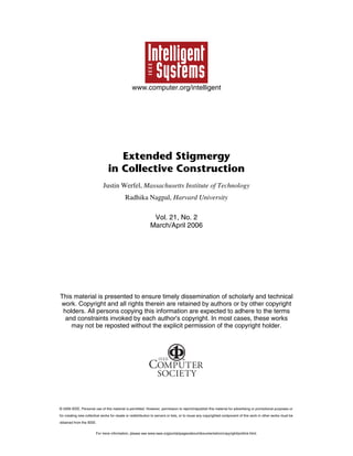
  • 7. Total distance traveled In general, the time required to build a given structure is a function of several factors: • the structure’s size and shape; • the number of robots, N; • the time required for a robot to fetch a block and bring it to the structure, L; • the time required for a robot to attach a block, A; and • the distance a robot must travel along the perimeter after reaching the structure before it finds a valid attachment site, D. We measure time in units such that it takes one time step to travel the length of one cell of the structure grid. L is typically task specific, and A is implementation specific. Because D, by contrast, depends primarily on the algorithm used, we focus on that quantity in comparing the three approaches’ performance. We consider a fixed number of robots building an n ´ n square and investigate the total number of perimeter-following steps D¢ = ⌺D taken by all robots during construction. To the extent that interference between robots can be avoided, N robots will complete the structure N times faster than one robot. However, as robot density in the workspace increases, interference also increases as robots maneuver to avoid each other, reach the limit as to the amount of work they can do at one time, and so on. For this analysis, our model places blockcarrying robots randomly on a large circle surrounding the marker and moves them inward until they reach the perimeter. After a robot attaches a block, it moves instantaneously back to the surrounding circle and continues with another block. We make the cellular assumption that robots and blocks occupy discrete positions on a grid corresponding to the occupancy matrix. (Later, we discuss the consequences of relaxing this assumption to let robots have continuous-valued positions.) With communicating blocks, the best possible case for D¢(n) is 0: robots can always randomly end up on the perimeter at sites where blocks may be attached, making travel along the perimeter unnecessary. The worst case is O(n3): if the robots build one full row of the structure first and thereafter are especially unlucky as to where they reach the structure, they might have to travel a distance O(n) for each of the O(n2) blocks they attach. A case worse than O(n3) isn’t possible for a square structure because a robot will never MARCH/APRIL 2006 have to travel further than O(n) to attach any block, and only n2 blocks exist. With writeable blocks, the best case for D¢ is O(n2): new rows must be started n times, and each time a robot must travel distance O(n) to survey the entire row to verify that it’s empty. However, a robot can attach additional blocks in existing rows without traveling if the robot always reaches the structure at an inside corner. Here, too, the worst case is O(n3). With inert blocks, the best case occurs if the robot always hits the structure adjacent to the marker’s labeled side. Because robots only become eligible to attach blocks after passing that landmark, the structure grows in a stereotyped way, and we can write an exact expression for the number of steps. This expression is O(n3), because a robot must typically travel the length of a side (n) to find a place to attach a block for each of n2 blocks. The worst case is when the robot always hits the structure just past the landmark. Then it not only must travel the same distance to find an allowed attachment site but must also first circle the entire structure to find the landmark, adding O(n3) steps to D¢ . Table 1 summarizes these results. In addition to the best and worst cases for scaling behavior, the average case is of interest and can be measured experimentally. For structures of side lengths {10, 20, 30, 40, 50} and 10 robots, we performed 10 independent runs in which we measured D¢ (see the table and figure 7a). With writeable and inert blocks, average scaling is close to the worst case. Furthermore, the multiplicative factor is considerably better for writeable than for inert blocks: although the two scale similarly with structure size, the former is consistently about three times faster. With communicating blocks, the average scaling behavior is significantly better than for the other two approaches, though still far from the theoretical best case. Parallelism At any stage of construction, there will be some number of simultaneously eligible sites E E I E E E E E Figure 6. A sample structure in progress. Blocks have darker shading; empty sites meant to be occupied have light shading. E indicates an end-of-row site; I, an inside corner. where robots could attach blocks. This number reflects the shape in which the structure grows. It also affects how much robots can do at any given time—that is, the extent to which the system can exploit the swarm’s parallelism. Figure 7b shows the maximum number of available sites over the course of a run for our experiments on square structures of varying side lengths. Because of the stereotyped way that structures grow with the inert-blocks algorithm, only one site is ever admissible for attachment at a time. Writeable blocks allow slightly more parallelism: not being limited to a single landmark to establish position lets robots work on all four sides of the structure at once. Still, no more than four sites can be simultaneously available, regardless of the structure’s eventual size. Communicating blocks let many more sites be simultaneously available for attachment. Moreover, that availability scales up with structure size. We can explain this as follows. If we assume that N is arbitrarily large and ignore interference between robots, some robot will always be present to attach a block at any allowed site. So, we can see construction as taking place in a series of steps of length A, where, at each step, blocks are attached at all allowed sites. As figure 8a shows, with write- Table 1. Best, worst, and average cases for the total number of steps robots must take along the perimeter when building an n ´ n square. Case Inert blocks Writeable blocks Communicating blocks Best 2n 3 – n – 1 n2 + n – 1 0 Worst 5n 3 + 3n 2 – 4n – 5 O(n 3) O(n3) Average ~(3.03 Âą 0.03)n 2.981Âą0.003 www.computer.org/intelligent ~(1.1 Âą 0.2)n 2.93Âą0.07 ~(2.5 Âą 0.6)n 2.36Âą0.06 25
  • 8. S e l f - M a n a g i n g S y s t e m s Steps along perimeter 10 10 10 (a) 5 4 Max number of allowed sites 50 Inert blocks Writeable blocks Communicating blocks Inert blocks Writeable blocks Communicating blocks 40 30 20 10 3 10 0 1 Side length 10 20 (b) 30 Side length 40 50 Figure 7. (a) Total number of steps taken along structure perimeter as a function of structure side length. (b) Maximum number of sites during construction where robots could simultaneously attach blocks. Placed at step: 1 2 3 4 5 6 7 8 (a) (b) Figure 8. If the number of robots N is arbitrarily large, then at the end of each step of length A, we can assume that blocks will be attached at every site where it is legal to do so (blocks attached at successive steps are shown successively lighter): (a) writeable blocks, (b) communicating blocks. able blocks, each step will have four allowed sites. This is because robots must first pass through an end-of-row site before they may attach a block at another end-of-row site. The time required to attach n blocks thus scales like nA. With communicating blocks (figure 8b), the number of allowed sites can increase linearly with the step number (along with the perimeter) if the structure’s design doesn’t limit growth. At step t, then, O(t) blocks will be attached, so the time to attach n blocks scales like n A. 26 Total construction time The minimum possible number of steps required to assemble any given structure, assuming an unlimited number of noninterfering robots, is equal to the longest shortest distance from the marker. That is, if we start at any block in the desired final structure and take one-cell hops to adjacent structure blocks, we must make some minimum number of hops dmin to reach the marker; the fastest possible construction time is the maximum dmin among all blocks in the structure. www.computer.org/intelligent This is because a robot can only attach a block if there are neighbors in the structure to attach it to, and an inductive approach shows that the earliest step in which any block could possibly be attached is the one equal to its shortest distance from the marker. The communicating-blocks approach achieves this minimum-possible construction time. Lemma. No two adjacent blocks can have the same distance from the seed dmin. Proof. Because the seed is unique and occupies one site, we can tile the plane like a checkerboard, where white squares are an even distance from the seed and red squares are an odd distance, as figure 9 shows. Theorem. With an unlimited number of noninterfering robots, the communicatingblocks algorithm results in each site that’s meant to be occupied becoming occupied on the step that’s equal to its shortest distance from the marker, dmin. Proof. The proof is by induction. For sites adjacent to the seed, the proof is trivial. Next, consider a structure after t steps, where every perimeter block has dmin ≤ t. Less than t is possible only if sites neighboring those blocks are intended to be left empty; otherwise, blocks would already have been attached at those sites, by assumption. Then, for any sites bordering the perimeter that are meant to be occupied, dmin = t + 1. As we now show, every one of those sites will have a block attached at the next time step (t + 1) without conflict. Figure 10 shows the three possible cases. IEEE INTELLIGENT SYSTEMS
  • 9. In the first case (figure 10a), a block can be attached at an inside corner, extending two existing rows. Such an attachment can’t result in a violation of the separation rule. Because the new block starts no new rows, if a violation were to occur at the next time step, it would also occur in the block’s absence. Thus, attachment at such a site won’t result in conflict and is always allowed. In the second case (figure 10b), a block starts a new row. If only one such block is to be attached in the new row at the next time step, the attachment won’t violate the separation rule. The third, and the only potentially problematic, case (figure 10c) involves adding two blocks in the same new row at the same time. Using the lemma presented earlier, at least one site must separate these two blocks (marked by question marks in the figure). If they’re meant to be separated, they can both be attached at once without conflict. A problem, then, can only arise if all sites between them are meant to be occupied. The two blocks must border the structure on the same side, as figure 10 shows; otherwise, either the partial structure violates the separation rule or the structure design has a loop in it, neither of which is allowed. The two new blocks’ old neighbors (X in figure 10c) have dmin = t, by hypothesis. Because all sites between the new blocks are meant to be occupied, all sites between the X blocks must also be meant to be occupied, or the structure design would have a loop. Furthermore, by step t, all sites between the X blocks must be occupied, or the structure would have violated the separation rule. The occupied sites adjacent to the X blocks (Y in the figure) must have dmin = t – 1. If they had dmin = t + 1, they would still be unoccupied by hypothesis. According to the lemma, they can’t have dmin = t, and, if they had dmin < t – 1, the X blocks would have been occupied earlier, by hypothesis. So, the sites adjacent to both the Y blocks and the ? blocks (Z in figure 10c) have dmin = t, and thus must be occupied by hypothesis. In this case, however, the ? blocks aren’t starting a new row. This contradiction completes the proof. With writeable or inert blocks, the structure typically has fewer sites where blocks can be attached at any given time, as we described earlier. Using the cellular assumption, writeable blocks allow only one row per side to be simultaneously under construction. As figure 11 indicates, robots can work on separated rows on the same side at the same time, but they can’t start on the next layer outward until MARCH/APRIL 2006 they complete the previous row. Using the inert-blocks algorithm, robots attach blocks no more than one at a time in a predictable order. Thus, completing an n-block structure will require n attachment steps, no matter the number of robots. (Alternative algorithms for inert blocks, not covered here, can somewhat improve the opportunity for parallelism, but not better than writeable blocks.) If we relax the cellular assumption, robots might be able to reach the structure between grid sites such that they recognize an end-ofrow but not an inside corner (see figure 12). Robots building with writeable blocks can then end up with two or more layers on the same side under construction at once. This can change some of our results for writeable blocks (results for communicating and inert blocks aren’t affected). It improves the bestpossible case for D¢(n) to O(n). More than four sites can become available for block 4 3 2 3 4 3 2 1 2 3 2 1 * 1 2 3 2 1 2 3 4 3 2 3 4 Figure 9. Sites labeled with their distance from the seed (marked with an *). attachment at a time, allowing better use of swarm parallelism and faster construction. However, the way the robot has to reach the structure for this case to occur makes it a low- X ? (a) (b) Y X ? ? Y Z Z ? (c) Figure 10. Three possible cases where robots might attach blocks (marked with a ?) at step t + 1: (a) attaching a block at an inside corner, (b) attaching a single block in a new row, and (c) adding two blocks in the same new row. Figure 11. A desired structure under construction using writeable blocks (lightly shaded cells show the desired structure; darker shading indicates blocks added so far). Arrows indicate that one row per structure side can be simultaneously under construction. Separations caused by areas meant to be left empty, such as those at the top and bottom, allow rows on the same side to be treated independently. www.computer.org/intelligent 27
  • 10. S e l f - M a n a g i n g S y s t e m s T h e A A u t h o r s Justin Werfel is a doctoral student in the Computer Science & Artificial B C Figure 12. If a robot reaches a structure between grid sites as in the case illustrated, and its sensing is sufficiently limited such that it can perceive the block at B but not at A, it could start following the perimeter counterclockwise, register the end-of-row as it turns the corner, and attach a block at C. Such an attachment isn’t possible under the cellular assumption. probability event. Thus, although relaxing the cellular assumption can substantially improve best-case performance, it’s unlikely to significantly affect average performance. I mportant work remains to extend this approach to other classes of structures, including structures with deliberate holes and 3D structures. Another important issue is the use of explicit communication between robots.6 More-extensive cooperation could let robots handle tasks that they couldn’t accomplish alone,7 help reduce interference, or achieve better than a factor of N speedup. An open question is to what other problems extended stigmergy might usefully be applied. We expect it to be a useful framework for coordinating other multiagent systems that can affect their environment, potentially offering advantages like those shown here over the basic stigmergy that’s been used in foraging and other swarm applications. We also hope that approaches like those we described will be useful in large-scale construction systems and will help to enable human presence in unfriendly environments. In addition, researchers could apply these principles to other production technologies in which mobile robots construct objects on smaller scales. Ultimately these could include nanofabrication or rapid-prototyping systems. Intelligence Laboratory at the Massachusetts Institute of Technology. His research interests include swarm engineering, evolutionary theory, and reinforcement learning. He has an SM in computer science from MIT. He is a member of the IEEE Robotics and Automation Society and Sigma Xi. Contact him at MIT 32-386, 32 Vassar St., Cambridge, MA 02139; jkwerfel@ mit.edu. Radhika Nagpal is an assistant professor of computer science at Harvard University. Her research interest is in biologically inspired approaches to multiagent and distributed systems. She received her PhD in computer science from MIT. Contact her at 235 Maxwell Dworkin, 33 Oxford St., Cambridge, MA 02138: rad@eecs.harvard.edu. 2. P.-P. GrassĂŠ, “La Reconstruction du Nid et les Coordinations Interindividuelles Chez Bellicositermes natalensis et Cubitermes sp. La Theorie de la Stigmergie: Essai d’Interpretation du Comportement des Termites Constructeurs” (“Nest Rebuilding and Coordination between Individuals for Bellicositermes natalensis and Cubitermes sp. Theory of Stigmergy: Attempting to Interpret the Behavior of Builder Termites”), Insectes Sociaux, vol. 6, 1959, pp. 41–81 (in French). 3. J. Werfel et al., “Distributed Construction by Mobile Robots with Enhanced Building Blocks,” to be published in Proc. 2006 IEEE Int’l Conf. Robotics and Automation, IEEE Press, 2006. 4. J. Werfel, “Building Blocks for Multiagent Construction,” Distributed Autonomous Robotic Systems, Springer, 2004. 5. C. Parker, H. Zhang, and R. Kube, “Blind Bulldozing: Multiple Robot Nest Construction,” Proc. 2003 IEEE Int’l Conf. Intelligent Robots and Systems, IEEE CS Press, 2003, pp. 2010–2015. 6. C. Jones and M. Mataric¢, “Automatic Synthesis of Communication-Based Coordinated Multirobot Systems,” Proc. 2004 IEEE/RSJ Int’l Conf. Intelligent Robots and Systems, IEEE Press, 2004, pp. 381–387. 7. B. Gerkey and M. Mataric “Pusher-Watcher: ¢, An Approach to Fault-Tolerant Tightly Coupled Robot Coordination,” Proc. 2002 IEEE Int’l Conf. Robotics and Automation, IEEE Press, 2002, pp. 464–469. References 1. A. Warszawski and R. Navon, “Implementation of Robotics in Buildings: Current Status and Future Prospects,” J. Construction Eng. and Management, vol. 124, no. 1, 1998, pp. 31–41. 28 IEEE Pervasive Computing For more information on this or any other computing topic, please visit our Digital Library at www.computer.org/publications/dlib. www.computer.org/intelligent IEEE Pervasive Computing delivers the latest developments in pervasive, mobile, and ubiquitous computing. With content that’s accessible and useful today, the quarterly publication acts as a catalyst for realizing the vision of pervasive (or ubiquitous) computing Mark Weiser described more than a decade ago—the creation of environments saturated with computing and wireless communication yet gracefully integrated with human users. SUBSCRIBE NOW! www.computer.org/pervasive/subscribe.htm IEEE INTELLIGENT SYSTEMS