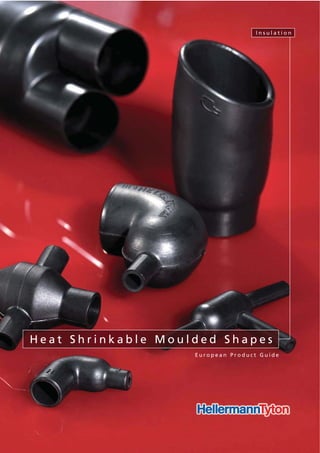
Hellermann Tyton Heat Shrink Moulded Shapes - Cable Boots, Breakouts, Caps, Transitions
•
0 likes•7,882 views

This document provides an overview and technical information about heat shrinkable moulded shapes from HellermannTyton. It includes a selection guide for low profile and bulbous boots and transitions with technical specifications for different product series. It also covers materials, adhesives, tubing, adaptor springs and contact information for HellermannTyton locations globally.

Recommended
More Related Content
Viewers also liked
Viewers also liked (20)
Similar to Hellermann Tyton Heat Shrink Moulded Shapes - Cable Boots, Breakouts, Caps, Transitions
Similar to Hellermann Tyton Heat Shrink Moulded Shapes - Cable Boots, Breakouts, Caps, Transitions (20)
More from Thorne & Derrick International
More from Thorne & Derrick International (20)
Recently uploaded
Recently uploaded (20)
Hellermann Tyton Heat Shrink Moulded Shapes - Cable Boots, Breakouts, Caps, Transitions
- 1. E u r o p e a n P r o d u c t G u i d e H e a t S h r i n k a b l e M o u l d e d S h a p e s I n s u l a t i o n WWW.CABLEJOINTS.CO.UK THORNE & DERRICK UK TEL 0044 191 490 1547 FAX 0044 477 5371 TEL 0044 117 977 4647 FAX 0044 977 5582 WWW.THORNEANDDERRICK.CO.UK
- 2. Our Corporate Philosophy 4 Our partners, local and global Contacts 6 Moulded Shapes Expertise 8 1 Technical Introduction Selection Guide 10 Selection Guide Overview • Low Profile Boots and Transitions 12 • Bulbous Boots and Transitions 12 • Bulbous Boots and Transitions 13 Technical Information • Materials for Heat Shrinkable Moulded Shapes 14 • Adhesives for Heat Shrinkable Moulded Shapes 15 Material & Adhesive combinations search 16 2.1 Low Profile Boots and Transitions Low Profile Convolute Boots • Helashrink 313C Series, with adapter lip 22 Low Profile Shim Boots • Helashrink 313E Series, without adapter lip 23 Low Profile Straight Boots • Helashrink 313F Series, with adapter lip 24 Low Profile Right Angle Boots • Helashrink 333F Series, with adapter lip, 90° angle 25 Low Profile Transition Boots • Helashrink 412H Series, side breakout 26 • Helashrink 492H Series, 1 to 2 cables 27 • Helashrink 573H Series, 1 to 3 cables 28 2.2 Bulbous Boots and Transitions Bottle Shapes, VG style • Helashrink 150 Series, with rib 29 Bottle Shapes, MIL style • Helashrink 100 Series, with rib 31 Bottle Shapes • Helashrink 100 Series, without rib 32 • Helashrink 120 Series, with and without rib 34 Long Outlet Shape, VG style • Helashrink 130 Series, with rib, low profile 35 Long Outlet Shapes • Helashrink 140 Series, without rib 37 Bottle Shapes • Helashrink 160 Series, without rib 38 Bottle Shapes, VG style • Helashrink 170 Series, with rib 39 • Helashrink 190 Series, with external ribs 40 2-Way Outlet Shapes • Helashrink 200 Series, low profile 41 2-Way Outlet Shapes, VG style • Helashrink 200 Series 42 2-Way Outlet Shapes, Breakout Boots • Helashrink 200 Series, in line, low voltage 43 3-Way Outlet Shapes, VG style • Helashrink 300 Series 44 3-Way Outlet Shapes, Breakout Boots • Helashrink 300 Series, in line, low voltage 45 4-Way Outlet Shapes, VG style • Helashrink 400 Series 46 4-Way Outlet Shapes, Breakout Boots • Helashrink 400 Series, in line, low voltage 47 5-Way Outlet Shapes, Breakout Boots • Helashrink 500 Series, in line, low voltage 48 6-Way Outlet Shapes, Breakout Boots • Helashrink 600 Series, in line, low voltage 49 Right Angle Shapes, VG style • Helashrink 1100 Series, with rib 50 • Helashrink 1100 Series, without rib, thick wall 51 Right Angle Shapes, MIL style • Helashrink 1100 Series, with rib 52 Right Angle Shapes • Helashrink 1100 Series, without rib 53 Right Angle Shapes, VG style/MIL style • Helashrink 1100 Series, with rib, low profile 54 Page Page
- 3. Right Angle Shapes, VG style • Helashrink 1100 Series, with rib, low profile, high ratio 56 T-Shapes, VG style • Helashrink 1200 Series 57 T-Shapes • Helashrink 1200 Series, Offset 58 T-Shapes, VG style • Helashrink 1200 Series, Offset 59 Angled T-Shapes, VG style • Helashrink 1300 Series, 30° & 45° angle 60 Double T-Shapes • Helashrink 1310 Series, 30° angle 61 Angle Elbow Shapes • Helashrink 1400 Series, 90° angle 62 Connector Cover for Min-D Series • Helashrink 1500 Series, with top entry 63 GSR Graduated Strain Relief • Helashrink 1750 Series with rib 64 Angle Shapes • Helashrink 1800 Series, with rib, 30°, 45°, 60° angle 65 Right-Angle Cross Shapes • Helashrink 2000 Series - T-Joint 66 Locating Bushes • Helashrink 1760, 1790, 1820 Series 67 Connector Cover for Min-D Series • Helashrink 2100 Series, with 90° entry 68 3.1 Breakout Boots and End Caps 2-Way Outlet Shapes, Breakout Boots • Helashrink 200 Series, in line, low voltage 70 3-Way Outlet Shapes, Breakout Boots • Helashrink 300 Series, in line, low voltage 71 4-Way Outlet Shapes, Breakout Boots • Helashrink 400 Series, in line, low voltage 72 End Caps • Helashrink 1600 Series, low voltage 73 Pinched End Caps • Helashrink PEC Series, low voltage 74 3.2 Heat Shrinkable Tubing Heat Shrinkable Tubing 2:1 - Fluororubber • Viton®-E 75 Heat Shrinkable Tubing 2:1 - Elastomer • SE28 76 • TE28 - light weight 77 Heat Shrinkable Tubing up to 4:1 - 1 m lengths • MU47 - medium wall unlined 78 • MA47 - medium wall adhesive lined 3.3 Adaptor Springs Constant Force Spring Adaptor • Zetalok 79 3.4 Adhesives Two-component Adhesive for Heat Shrinkable Tubing and Shapes • V9500 Dosing Gun 80 Hot Melt Tape for Heat Shrinkable Tubing and Shapes • HMT200A 81 High Temperature Hot Melt Adhesive Tape for Low Profile Products • TSA 200 82 4.1 HellermannTyton Product Standards Standards for HellermannTyton Heat Shrinkable Tubing and Heat Shrinkable Moulded Shapes according to VG Norm 84 Standards for HellermannTyton Heat Shrinkable Tubing 85 VG/MIL Specification Cross Reference 86 HellermannTyton Shapes for use with MIL Connectors 87 MIL Specification Slash Sheet Cross Reference 88 4.2 Terms and Conditions 95 Page Page Content
- 4. 4 Moving the market takes more than good ideas. Developing the product solutions for the future, requires visionary thinking and the passion to turn ideas into reality. When visions become functional products, innovations are generated that benefit our customers. We create the conditions for this by employing motivated people who are committed to working as a team. When only the best solutions will do, you need dedicated professionals with expert knowledge. The result is product solutions that not only reshape the market but re-develope it. We are able to offer product solutions before our customers know they need them. We maintain good relationships with our customers and also keep a close eye on the latest market developments. This allows us to recognise trends affecting trade and industry at an early stage. And enables us to remain a step ahead of customer requirements at all times. Meeting high expectations calls for ongoing development. As well as paying particular attention to communicating with our customers and knowledge of the market, we invest heavily in research and development. To ensure that we can support our customers into the future by offering custom product solutions, we continually optimise our technical and logistical processes.
- 5. 5 Certified processes and quality, for your security. HellermannTyton always aim for the highest quality. To live up to this claim we have implemented a quality and environmental management systems. Our quality management is certified to DIN EN ISO 9001:2008 and DIN EN ISO/TS 16949:2002. In addition, our environmental management complies with the requirements of DIN EN ISO 14001:2005. At your service wherever – and whenever – you need us. What use are the best product solutions if they are not available to local markets in a timely way? HellermannTyton’s motto is therefore “Think global, act local”. For us, this not only means responding to the needs of local markets – we also have a presence there for the benefit of our customers. Employees on the ground allow us to cater for cultural, market- specific and linguistic factors effectively. In addition, our customers have access to a worldwide distribution network. This adds value that makes us one of the leading providers for trade and industry. O u r C o r p o r a t e P h i l o s o p h y To t r u l y e x c e l , y o u n e e d t o k e e p i m p r o v i n g a l l t h e t i m e . DIN EN ISO 9001:2000 DIN EN ISO 14001:2004 DIN EN ISO/TS 16949:2002
- 6. 6 W h e n e v e r y o u n e e d u s . . . ... you will find your local contact here: www.HellermannTyton.com E u ro p e HellermannTyton GmbH – Austria Obachgasse 6 1221 Vienna Tel: +43 (0) 1 259 99 55 - 0 Fax: +43 (0)1 259 99 11 E-Mail: office@HellermannTyton.at www.HellermannTyton.at HellermannTyton B.V. – Belgium E-Mail: info@HellermannTyton.be www.HellermannTyton.be HellermannTyton – Czech Republic E-Mail: office.cz@HellermannTyton.at www.HellermannTyton.cz HellermannTyton Denmark Baldersbuen 15D 1. TV 2640 Hedehusene Tel: +45 702 371 20 Fax: +45 702 371 21 E-Mail: htdk@HellermannTyton.dk www.HellermannTyton.dk HellermannTyton Oy – Finland Sähkötie 8 01510 Vantaa Tel: +358 9 8700 450 Fax: +358 9 8700 4520 E-Mail: myynti@HellermannTyton.fi www.HellermannTyton.fi HellermannTyton S.A.S. – France 2 rue des Hêtres, B.P. 130 78196 Trappes Cedex Tel: +33 1 30 13 80 00 Fax: +33 1 30 13 80 60 E-Mail: info@HellermannTyton.fr www.HellermannTyton.fr HellermannTyton GmbH – Germany Großer Moorweg 45 25436 Tornesch Tel: +49 4122 701-0 Fax: +49 4122 701-400 E-Mail: info@HellermannTyton.de www.HellermannTyton.de HellermannTyton KFT – Hungary Kisfaludy u. 13 1044 Budapest Tel: +36 1 369 4151 Fax: +36 1 369 4151 E-Mail: office@HellermannTyton.hu www.HellermannTyton.hu HellermannTyton S.r.l. – Italy Via Praimbole 9 Bis 35010 Limena (PD) Tel: +39 049 767 870 Fax: +39 049 767 985 E-Mail: info@HellermannTyton.it www.HellermannTyton.it HellermannTyton Ltd – Ireland Unit 77 Cherry Orchard Industrial Estate Ballyfermot, Dublin 10 Tel: +353 1 626 8267 Fax: +353 1 626 8022 E-Mail: sales@HellermannTyton.ie www.HellermannTyton.co.uk HellermannTyton B.V. – Netherlands Vanadiumweg 11-C 3812 PX Amersfoort Tel: +31 33 460 06 90 Fax: +31 33 460 06 99 E-Mail: info@HellermannTyton.nl www.HellermannTyton.nl HellermannTyton AS – Norway PO Box 240 Alnabru 0614 Oslo Tel: +47 23 17 47 00 Fax: +47 22 97 09 70 E-Mail: firmapost@HellermannTyton.no www.HellermannTyton.no HellermannTyton – Poland E-Mail: info@HellermannTyton.pl www.HellermannTyton.pl OOO HellermannTyton – Russia St. Petersburg E-Mail: info@HellermannTyton.ru www.HellermannTyton.ru HellermannTyton – Slovenia Branch Office Ljubljana Trubarjeva 79 1101 Ljubljana Tel: +386 1 433 70 56 Fax: +386 1 433 63 21 E-Mail: sales@HellermannTyton.si www.HellermannTyton.si HellermannTyton España s.l. – Spain/Portugal Avda. de la Industria nº 37, 2º 2ª 28.108 Alcobendas, Madrid Tel: +34 91 661 2835 Fax: +34 91 661 2368 E-Mail: HellermannTyton@HellermannTyton.es www.HellermannTyton.es HellermannTyton AB – Sweden Datavägen 5, PO Box 569 17526 Järfälla Tel: +46 8 580 890 00 Fax: +46 8 580 890 01 E-Mail: support@HellermannTyton.se www.HellermannTyton.se HellermannTyton Ltd – UK Manufacturing Site William Prance Road Plymouth International Technology Park Plymouth PL6 5WR United Kingdom Tel: +44 (0) 1752 761211 Fax: +44 (0) 1752 761210 E-Mail: info@HellermannTyton.co.uk www.HellermannTyton.co.uk HellermannTyton Ltd – UK Manufacturing Site Sharston Green Business Park 1 Robeson Way Altrincham Road, Wythenshawe Manchester M22 4TY Tel: +44 161 945 4181 Fax: +44 161 947 2220 E-Mail: info@HellermannTyton.co.uk www.HellermannTyton.co.uk HellermannTyton Ltd – UK Main Contact for Customer Service Wharf Approach Aldridge, Walsall, West Midlands WS9 8BX Tel: +44 1922 458 151 Fax: +44 1922 743 237 E-Mail: info@HellermannTyton.co.uk www.HellermannTyton.co.uk HellermannTyton Data Ltd – UK 43-45 Salthouse Road Cornwell Business Park Brackmills Northampton NN4 7EX Tel: +44 1604 707 420 Fax: +44 1604 705 454 E-Mail: hns@htdata.co.uk www.htdata.co.uk N o r t h A m e r i c a HellermannTyton – Canada Tel: +1 905 726 1221 Fax: +1 905 726 8538 E-Mail: sales@HellermannTyton.ca www.HellermannTyton.ca HellermannTyton – Mexico Tel: +52 333 133 9880 Fax: +52 333 133 9861 E-Mail: info@HellermannTyton.com.mx www.HellermannTyton.com HellermannTyton – USA Tel: +1 414 355 1130 Fax: +1 414 355 7341 E-Mail: corp@htamericas.com www.HellermannTyton.com S o u t h A m e r i c a HellermannTyton – Argentina Tel: +54 11 4754 5400 Fax: +54 11 4752 0374 E-Mail: ventas@HellermannTyton.com.ar www.HellermannTyton.com.ar HellermannTyton – Brazil Tel: +55 11 4815 9000 Fax: +55 11 4815 9030 E-Mail: vendas@HellermannTyton.com.br www.HellermannTyton.com.br A s i a - P a c i f i c HellermannTyton – Australia Tel: +61 2 9525 2133 Fax: +61 2 9526 2495 E-Mail: cservice@HellermannTyton.com.au www.HellermannTyton.com.au HellermannTyton – China Tel: +86 510 528 2536 Fax: +86 510 528 0112 E-Mail: cservice@HellermannTyton.com.cn www.HellermannTyton.com.cn HellermannTyton – Hong Kong Tel: +852 2832 9090 Fax: +852 2832 9381 E-Mail: cservice@HellermannTyton.com.hk www.HellermannTyton.com.sg HellermannTyton – India Tel: +91 11-2620 9230/6661 9230 Fax: +91 11-2620 9330/6661 9330 E-Mail: cservice@HellermannTyton.co.in www.HellermannTyton.co.in HellermannTyton – Japan Tel: +81 3 5790 3111 Fax: +81 3 5790 3112 E-Mail: cservice@HellermannTyton.co.jp www.HellermannTyton.co.jp HellermannTyton – Korea Tel: +82 2 2614 0157 Fax: +82 2 2614 0284 E-Mail: cservice@HellermannTyton.co.kr www.HellermannTyton.co.kr HellermannTyton – Philippines Tel: +63 2 752 6551 Fax: +63 2 752 6553 E-Mail: cservice@HellermannTyton.com.ph www.HellermannTyton.com.ph HellermannTyton – Singapore Tel: +65 6 852 8585 Fax: +65 6 756 6798 E-Mail: cservice@HellermannTyton.sg www.HellermannTyton.com.sg HellermannTyton – Thailand Tel: +66 2 237 6702 Fax: +66 2 266 8664 E-Mail: cservice@HellermannTyton.com.th www.HellermannTyton.com.sg A f r i c a HellermannTyton – South Africa Tel: +27 11 879 6680 Fax: +27 11 879 6601 E-Mail: sales.jhb@Hellermann.co.za www.HellermannTyton.co.za
- 7. 7 Contact If you have a particular problem that you would like us to help you with then please contact us. With our vast experience and practically unlimited technical capabilities we are confident of being able to help you find a solution. Remember, we are a service provider and not just a supplier. Give us a call! Here are your contacts for enquiries and orders For all product information please visit our Website www.HellermannTyton.co.uk Heat Shrinkable Moulded Shapes Plymouth Telephone 00 44 1752 701 261 Facsimile 00 44 1752 790 058 e-mail heatshrinkshapes@HellermannTyton.co.uk Aldridge Telephone 00 44 1922 458 151 Facsimile 00 44 1922 743 237 e-mail heatshrinkshapes@HellermannTyton.co.uk General Contacts UK Head Office Telephone 00 44 161 945 4181 Facsimile 00 44 161 947 2233 e-mail ukho@HellermannTyton.co.uk OEM Sales - Fixings & Fastenings Telephone 00 44 161 947 2200 Facsimile 00 44 161 945 3708 e-mail sales@HellermannTyton.co.uk OEM Sales - Insulation & Protection Telephone 00 44 1752 701 261 Facsimile 00 44 1752 790 058 e-mail insulation&protection@HellermannTyton.co.uk OEM Sales - Identification Telephone 00 44 1752 701 261 Facsimile 00 44 1752 790 058 e-mail identification@HellermannTyton.co.uk OEM Sales - Automated Systems Telephone 00 44 161 947 2200 Facsimilie 00 44 161 945 3708 e-mail automatedsystems@HellermannTyton.co.uk
- 8. 8 Heat Shrinkable Moulded Shapes Expertise HellermannTyton heat shrinkable moulded shapes combine the advantages of quick, easy installation with high electric strength, mechanical toughness and superior chemical and environmental resistance. Our products offer important functional and cost saving benefits for electrical and electronic applications ranging from insulation and protection of individual compo- nents to fabrication of complete inter-connecting cable harness assemblies. Strain-relieving boots, transitions and connector backshell covers, as well as other specialised shapes, are available in a wide range of sizes and options. HellermannTyton's extensive product line includes low profile, bulbous and lipped types for use on circular and D-type connectors as well as complex multiway transitions. Only a minimum number of shapes are needed to cover a full range of applications as the products have high shrink ratios of up to 5:1. Applications The use of our heat shrinkable moulded shapes in conjunction with our specialist heat shrinkable tubings makes it easy to fabricate complete jacketed wire and cable harnessing and interconnection systems of the highest quality. Heat shrinkable shapes are available for the complete range of electrical and electronic harnessing applications. They can be sealed with our special adhesives and encapsulants to ensure the proper degree of mechanical support, strain relief and environmental protection. Encapsulating the complete harnessing and interconnection system to the desired configuration is easily and neatly accomplished, with minimum weight and bulk. Choice of Materials A range of specially formulated materials is available to meet a variety of performance requirements. Material selection can be made according to individual applications. We also have the ability to make customized materials to suit special requirements. Technical Capabilities Our materials are formulated in our own laboratory and produced in the HellermannTyton factory. We have experience and knowledge of all major applications and offer full technical support from design through to prototyping, to service. NOTE: Copyright to all drawings in this brochure is reserved by HellermannTyton. They are issued on condition that they are not copied, reproduced or disclosed to any third party either wholly or in part, without the written consent of HellermannTyton. H e a t S h r i n k a b l e M o u l d e d S h a p e s E x p e r t i s e
- 9. 1 Technical Information Selection Guide 10 Selection Guide Overview • Low Profile Boots and Transitions 12 • Bulbous Boots and Transitions 12 • Bulbous Boots and Transitions 13 Technical Information • Materials for Heat Shrinkable Moulded Shapes 14 • Adhesives for Heat Shrinkable Moulded Shapes 15 Material & Adhesive combinations search 16 Te c h n i c a l I n t r o d u c t i o n Page 1
- 10. I n s u l a t i o n Selection Guide 10 1 I n s u l a t i o n XXX 10 I n s u l a t i o n Selection Guide 10 This selection guide will help you to find the correct moulded shape for your application: Step 1. Product Style Use the Selection Guide Overview on page 12 to quickly select a suitable product profile. Step 2. Product Size Choose the correct dimensions to meet your application from our sizes and types table which appears on the relevant product profile page. An example of these tables is shown below: Step 3. Material/ Adhesive Choose a material and adhesive to meet your application requirements from the tables on page 14/15. Further combinations are available. Here is an example: These symbols denote the material or adhesive availability for each profile type. In this example the adhesive W21 is not available with the material B7,G, and B8 because of the ″-″. But it is available with the material H because of the ″√″. 3.1 Material Parts can be supplied in a choice of materials. The ″combinations″ table on each product page provides a quick and easy material recognition guide for the product profiled. The standard colour is black but other colours are available on request, please contact us for further information. On page 14 you will find detailed information on our range of materials.
- 11. I n s u l a t i o n Selection Guide 11 1 I n s u l a t i o n XXX 11 I n s u l a t i o n Selection Guide 11 6. Ordering Procedure When ordering heat shrinkable shapes, it is necessary to give a complete part number to enable efficient processing of your order. Part numbers can be made up of the following typical components: Example: 154 - 42 - G - P - W8 Presence and type of adhesive Filler ports add suffix ″P″; Drain holes add suffix ″D″ Material reference Expansion and special details Exact shape Step 4. Standard combinations To help you with your decision we offer standard combinations for each product type. In this example we offer the Type 223-2 in B8 material and with the adhesive W. 5. Special Modifications Filler ports and drain holes are also available where the injection of potting epoxy is required. P = Filler ports for potting – 3mm Ø vent and 4.5mm Ø filler. D = Drain holes 4 offset – 3mm Ø at H end equally spaced 90° apart. 3.2 Adhesive To maximise environmental protection and strain relief we recommend the use of an adhesive from our range below. Pre-lined hot melt adhesive: • WM250 • W • W2 • W8 • W21 Component adhesive: • HMT200A • W24 • V9500 • TSA-200 For further information on adhesives please refer to page 15.
- 12. Page 44 Page 42 Page 40 Page 38 Page 35 Page 32 Page 29 Page 31 Page 34 Page 37 Page 39 Page 41 Page 43 Page 45 I n s u l a t i o n Selection Guide Overview 12 1 Low Profile Boots and Transitions Bulbous Boots and Transitions Page 22 Page 23 Page 25 Page 27 Page 24 Page 26 Page 28 Low Profile Transition Boots Helashrink 573H Series, 1 to 3 cables Low Profile Shim Boots Helashrink 313E Series, without adapter lip Low Profile Right Angle Boots Helashrink 333F Series, with adapter lip, 90° angle Low Profile Convolute Boots Helashrink 313C Series, with adapter lip Low Profile Straight Boots Helashrink 313F Series, with adapter lip Low Profile Transition Boots Helashrink 412H Series, side breakout Low Profile Transition Boots Helashrink 492H Series, 1 to 2 cables Bottle Shapes Helashrink 160 Series, without rib Bottle Shapes, MIL style Helashrink 100 Series, with rib Bottle Shapes Helashrink 120 Series, with and without rib Bottle Shapes, VG style Helashrink 150 Series, with rib Bottle Shapes Helashrink 100 Series, without rib Long Outlet Shape, VG style Helashrink 130 Series, with rib, low profile Long Outlet Shapes Helashrink 140 Series, without rib Bottle Shapes, VG style Helashrink 170 Series, with rib 2-Way Outlet Shapes, VG style Helashrink 200 Series Bottle Shapes, VG style Helashrink 190 Series, with external ribs 2-Way Outlet Shapes Helashrink 200 Series, low profile 2-Way Outlet Shapes, Breakout Boots Helashrink 200 Series, in line, low voltage 3-Way Outlet Shapes, VG style Helashrink 300 Series 3-Way Outlet Shapes, Breakout Boots Helashrink 300 Series, in line, low voltage
- 13. I n s u l a t i o n 13 Selection Guide Overview 1 Page 46 Page 47 Page 49 Page 51 Page 53 Page 56 Page 58 Page 60 Page 62 Page 64 Page 66 Page 68 Page 48 Page 50 Page 52 Page 54 Page 57 Page 59 Page 61 Page 63 Page 65 Page 67 Bulbous Boots and Transitions Right Angle Shapes, MIL style Helashrink 1100 Series, with rib 4-Way Outlet Shapes, Breakout Boots Helashrink 400 Series, in line, low voltage 6-Way Outlet Shapes, Breakout Boots Helashrink 600 Series, in line, low voltage 4-Way Outlet Shapes, VG style Helashrink 400 Series 5-Way Outlet Shapes, Breakout Boots Helashrink 500 Series, in line, low voltage Right Angle Shapes, VG style Helashrink 1100 Series, with rib Right Angle Shapes, VG style Helashrink 1100 Series, without rib, thick wall Right Angle Shapes Helashrink 1100 Series, without rib Right Angle Shapes, VG style/MIL style Helashrink 1100 Series, with rib, low profile Right Angle Shapes, VG style Helashrink 1100 Series, with rib, low profile, high ratio T-Shapes, VG style Helashrink 1200 Series T-Shapes Helashrink 1200 Series, Offset T-Shapes, VG style Helashrink 1200 Series, Offset Angled T-Shapes, VG style Helashrink 1300 Series, 30° & 45° angle Double T-Shapes Helashrink 1310 Series, 30° angle Angle Elbow Shapes Helashrink 1400 Series, 90° angle Connector Cover for Min-D Series Helashrink 1500 Series, with top entry GSR Graduated Strain Relief Helashrink 1750 Series, with rib Locating Bushes Helashrink 1760, 1790, 1820 Series Connector Cover for Min-D Series Helashrink 2100 Series, with 90° entry Angle Shapes Helashrink 1800 Series, with rib, 30°, 45°, 60° angle Right Angle Cross Shapes Helashrink 2000 Series, T-Joint
- 14. 14 I n s u l a t i o n Technical Information1 Material Specifications Description -9 -8 -6 Material Modified elastomer blend Modified fluoroelastomer Flexible flame retarded polyolefin Continuous Operating Temperature °C -55 to +120 -55 to +150 -55 to +120 Minimum Shrink Temperature °C +135 +135 +135 Specifications SCX15112 SCX15111 MIL-1-81765/1 Type I + II Tensile Strength (MPa) 12 15 12 Ultimate Elongation (%) 500 450 500 Dielectric Strength kV/mm 20 20 20 Flammability (Self extinguishing) Excellent <25mm Excellent Characteristics Good physical and reasonable chemical resistance Good physical and chemical resistance Good physical and reasonable chemical resistance Typical applications Material Specifications Description B7 G J Material Semi-rigid flame retarded polyolefin Fluid resistant elastomer Flexible polyolefin Continuous Operating Temperature °C -55 to +135 -75 to +150 -55 to +135 Minimum Shrink Temperature °C +135 +135 +135 Specifications MIL-I-81765/1 TYPE I DEF 59-97 BSG198 Part 5 VG 95343 Pt6 & Pt18 DEF 59-97 BSG198 Part 5 MIL-1-81765/1 TYPE II DEF 59-97 BSG198 Part 5 Tensile Strength (MPa) 13 15 14 Ultimate Elongation (%) 500 580 610 Dielectric Strength kV/mm 14 14 12 Flammability (Self extinguishing) Excellent Excellent Excellent Characteristics Good physical and chemical resistance Excellent resistance to fuels Flexible Typical applications Military and general high performance harnessing Materials for Heat Shrinkable Moulded Shapes Material Specifications Description H B8 L Material Flexible limited fire hazard material Semi-rigid flame retarded polyolefin Flexible flame retarded fluoroelastomer Continuous Operating Temperature °C -55 to +105 -55 to +100 -55 to +200 Minimum Shrink Temperature °C +135 +135 +175 Specifications NAVSEA 5617649 DEF 59-97 VG 95343 Pt29 BSG198 Part 5 EA-TS 09-11 MIL-81765/4 DEF Stan 59-97 BSG198 Part 5 Tensile Strength (MPa) 10 15 12 Ultimate Elongation (%) 450 500 300 Dielectric Strength kV/mm 15 15 8 Flammability (Self extinguishing) Excellent Good Excellent Characteristics Low smoke Halogen free Good physical and reasonable chemical resistance High temperature excellent chem. resistance Typical applications Ships, submarines & railways Power/utility shapes Military and high performance harnessing Military and general high performance harnessing
- 15. 15 Technical Information I n s u l a t i o n 1 Adhesives for Heat Shrinkable Moulded Shapes Adhesive Specifications Description W / W2 WM250 W8 Adhesive General purpose hot melt adhesive General purpose hot melt adhesive EVA, high performance, hot melt adhesive Operating Temperature Range °C -55 to +80 -55 to +80 -55 to +105 Softening Point °C +95 +95 +110 Supplied Form pre-applied pre-applied pre-applied Shelf Life 5 years 5 years 5 years Solvent Resistance Adhesive Specifications Description W21 W24 TSA-200 Adhesive Modified polyamide hot melt adhesive High performance, pre-coat, 1 part epoxy Thermoset +125° C Operating Temperature Range °C -55 to +120 -75 to +200 -55 to +125 Softening Point °C +120 - - Supplied Form pre-applied pre-applied Tape Shelf Life 5 years 5 years 5 years Solvent Resistance Saline: Very good De-icing fluid: Good Diesel: Excellent Lubricating Oil: Good Hydraulic Oil: Good Aviation Fuel: Good Automotive Fuel: Good De-icing fluid: Excellent Petrol: Excellent Lubricating Oil: Excellent Hydraulic Oil: Excellent Fair under splash conditions Adhesive Specifications Description V9500 HMT200A Adhesive Two part, black, epoxy adhesive Hot melt adhesive tape Operating Temperature Range °C -75 to +150 -55 to +105 Softening Point °C - +110 Supplied Form Cartridge Tape Shelf Life 18 months 5 years Solvent Resistance De-icing fluid: Excellent Petrol: Excellent Lubricating Oil: Excellent Hydraulic Oil: Excellent Fair under splash conditions Fair under splash conditions
- 16. 16 I n s u l a t i o n Material & Adhesive Combinations Search1 Use this table to find the adhesive compatibility for your preferred material. Material Material Combinations G B7 B8 H Material Description Fluid resistant elastomer Semi -rigid flame retarded polyolefin Semi -rigid flame retarded polyolefin Flexible limited fire hazard polyolefin Shape Minimum Shrink Temperature °C +135 +135 +135 +135 Operating Temperature Range °C -75 to +150 -55 to +135 -55 to +100 -55 to +105 Shelf Life 5 years 5 years 5 years 5 years Helashrink 100 Series yes yes no yes Helashrink 1100 Series yes yes no yes Helashrink 200 Series yes yes no yes Helashrink 300 Series yes yes no yes Helashrink 400 Series yes yes no yes Helashrink 1200 Series yes yes no yes Helashrink 1300 Series yes yes no yes Low Profile Shapes (Series 313, 412, 492, 573) no no no no Helashrink 1600 Series no no yes no Helashrink In Line Series, low voltage no no yes no Adhesive Compatibility WM250 WM250 WM250 WM250 W8 W8 W8 W8 W24 W24 W24 V9500 V9500 W21 HMT200A HMT200A
- 17. 17 I n s u l a t i o n Material & Adhesive Combinations Search 1 Material Material Combinations L -9 -6 -8 Material Description Flexible flame retarded fluoroelastomer Modified elastomer blend Flexible flame retarded polyolefin Fluoro-elastomer polymer blend Shape low profile low profile low profile Minimum Shrink Temperature °C +175 +135 +135 +135 Operating Temperature Range °C -55 to +200 -55 to +120 -55 to +120 -55 to +150 Shelf Life 5 years Helashrink 100 Series yes no no no Helashrink 1100 Series yes no no no Helashrink 200 Series yes no no no Helashrink 300 Series yes no no no Helashrink 400 Series yes no no no Helashrink 1200 Series yes no no no Helashrink 1300 Series yes no no no Low Profile Shapes (Series 313, 412, 492, 573) no yes yes yes Helashrink 1600 Series no no no no Helashrink In Line Series, low voltage no no no no Adhesive Compatibility W24 WM250 WM250 WM250 W8 W8 W8 W24 W24 W24 V9500 V9500 V9500 HMT200A HMT200A HMT200A TSA200 TSA200 TSA200
- 18. 18 I n s u l a t i o n Material & Adhesive Combinations Search1 Use this table to find the material compatibility for your preferred adhesive. Adhesive Adhesive Combinations W / W2 WM250 W8 W21 Adhesive Description General purpose hot melt adhesive General purpose hot melt adhesive EVA, high performance, hot melt adhesive Modified polyamide hot melt adhesive Operating Temperature Range °C -55 to +80 -55 to +80 -55 to +105 -55 to +120 Softening Point °C +95 +95 +110 - Supplied Form pre-applied pre-applied pre-applied pre-applied Shelf Life 5 years 5 years 5 years 5 years Solvent Resistance Fair under splash conditions Fair under splash conditions Fair under splash conditions Saline: Very good De-icing fluid: Good Diesel: Excellent Lubricating Oil: Good Hydraulic Oil: Good Aviation Fuel: Good Automotive Fuel: Good Helashrink 100 Series no yes yes yes Helashrink 1100 Series no yes yes yes Helashrink 200 Series no yes yes yes Helashrink 300 Series no yes yes yes Helashrink 400 Series no yes yes yes Helashrink 1200 Series no yes yes yes Helashrink 1300 Series no yes yes yes Low Profile Shapes (Series 313, 412, 492, 573) no yes yes yes Helashrink 1600 Series yes yes no no Helashrink In Line Series, low voltage yes yes no no Material Compatibility B8 G G G B7 B7 B7 B8 H B8 H -6 H -6 -9 -9 -8 -8
- 19. 19 I n s u l a t i o n Material & Adhesive Combinations Search 1 Adhesive Adhesive Combinations W24 TSA-200 V9500 HMT200A Adhesive Description High performance, pre-coat, 1 part epoxy Thermoset +125°C Two part, black, epoxy adhesive Hot melt adhesive tape Operating Temperature Range °C -75 to +200 -55 to +125 -75 to +150 -55 to +105 Softening Point °C - - - + 110 Supplied Form pre-applied Tape Cartridge Tape Shelf Life 5 years 5 years 18 months 5 years Solvent Resistance De-icing fluid: Excellent Petrol: Excellent Lubricating Oil: Excellent Hydraulic Oil: Excellent Fair under splash conditions De-icing fluid: Excellent Petrol: Excellent Lubricating Oil: Excellent Hydraulic Oil: Excellent Fair under splash conditions Helashrink 100 Series yes no yes yes Helashrink 1100 Series yes no yes yes Helashrink 200 Series yes no yes yes Helashrink 300 Series yes no yes yes Helashrink 400 Series yes no yes yes Helashrink 1200 Series yes no yes yes Helashrink 1300 Series yes no yes yes Low Profile Shapes (Series 313, 412, 492, 573) yes yes yes yes Helashrink 1600 Series no no no yes Helashrink In Line Series, low voltage no no no yes Material Compatibility G -6 G G B7 -9 B7 B7 H -8 H B8 L H -6 -6 -9 -9 -8 -8
- 20. 2.1 Low Profile Boots and Transitions Low Profile Convolute Boots • Helashrink 313C Series, with adapter lip 22 Low Profile Shim Boots • Helashrink 313E Series, without adapter lip 23 Low Profile Straight Boots • Helashrink 313F Series, with adapter lip 24 Low Profile Right Angle Boots • Helashrink 333F Series, with adapter lip, 90° angle 25 Low Profile Transition Boots • Helashrink 412H Series, side breakout 26 • Helashrink 492H Series, 1 to 2 cables 27 • Helashrink 573H Series, 1 to 3 cables 28 2.2 Bulbous Boots and Transitions Bottle Shapes, VG style • Helashrink 150 Series, with rib 29 Bottle Shapes, MIL style • Helashrink 100 Series, with rib 31 Bottle Shapes • Helashrink 100 Series, without rib 32 • Helashrink 120 Series, with and without rib 34 Long Outlet Shape, VG style • Helashrink 130 Series, with rib, low profile 35 Long Outlet Shapes • Helashrink 140 Series, without rib 37 Bottle Shapes • Helashrink 160 Series, without rib 38 Bottle Shapes, VG style • Helashrink 170 Series, with rib 39 • Helashrink 190 Series, with external ribs 40 2-Way Outlet Shapes • Helashrink 200 Series, low profile 41 2-Way Outlet Shapes, VG style • Helashrink 200 Series 42 2-Way Outlet Shapes, Breakout Boots • Helashrink 200 Series, in line, low voltage 43 3-Way Outlet Shapes, VG style • Helashrink 300 Series 44 3-Way Outlet Shapes, Breakout Boots • Helashrink 300 Series, in line, low voltage 45 4-Way Outlet Shapes, VG style • Helashrink 400 Series 46 Page Page
- 21. H e a t S h r i n k a b l e M o u l d e d S h a p e s 4-Way Outlet Shapes, Breakout Boots • Helashrink 400 Series, in line, low voltage 47 5-Way Outlet Shapes, Breakout Boots • Helashrink 500 Series, in line, low voltage 48 6-Way Outlet Shapes, Breakout Boots • Helashrink 600 Series, in line, low voltage 49 Right-Angle Shapes, VG style • Helashrink 1100 Series, with rib 50 • Helashrink 1100 Series, without rib, thick wall 51 Right-Angle Shapes, MIL style • Helashrink 1100 Series, with rib 52 Right-Angle Shapes • Helashrink 1100 Series, without rib 53 Right-Angle Shapes, VG style/MIL style • Helashrink 1100 Series, with rib, low profile 54 Right-Angle Shapes, VG style/MIL style • Helashrink 1100 Series, with rib, low profile 55 Right-Angle Shapes, VG style • Helashrink 1100 Series, with rib, low profile, high ratio 56 T-Shapes, VG style • Helashrink 1200 Series 57 T-Shapes • Helashrink 1200 Series, Offset 58 T-Shapes, VG style • Helashrink 1200 Series, Offset 59 Angled T Shapes, VG Style • Helashrink 1300 Series, 30° & 45° angle 60 Double T Shapes • Helashrink 1310 Series, 30° angle 61 Angle Elbow Shapes • Helashrink 1400 Series, 90° angle 62 Connector Cover for Min-D Series • Helashrink 1500 Series, with top entry 63 GSR Graduated Strain Relief • Helashrink 1750 Series, with rib 64 Angle Shapes • Helashrink 1800 Series, with rib, 30°, 45°, 60° angle 65 Right-Angle Cross Shapes • Helashrink 2000 Series - T-Joint 66 Locating Bushes • Helashrink 1760, 1790, 1820 Series 67 Connector Cover for Min-D Series • Helashrink 2100 Series, with 90° entry 68 Page Page 2
- 22. 22 I n s u l a t i o n Low Profile Boots and Transition2.1 Low Profile Boots and Transitions Adhesive Material 9 8 6 TSA-200 √ √ √ WM250 √ √ √ W8 √ √ √ W24 √ √ √ V9500 √ √ √ HMT200A √ √ √ Without Adhesive √ √ √ b: Fully recovered form (after heating) • Helashrink 313C Series, with adapter lip T ØH R S P JO- W ØJ B Article-No. Type 422-00001 313C722-9 422-00101 313C732-9 422-00201 313C743-9 422-00302 313C753-9 422-00400 313C764-9 422-00501 313C774-9 Low Profile Convolute Boots This style is used with a circular grooved adapter to provide strain relief and, if adhesive is used, excellent environmental sealing can be achieved. The convoluted design provides the flexibility to accommodate different cable outlet angles. 313C722-774 Series supplied / fully recovered. a: Expanded form (supplied) Standard combinationsCombinations ″On request″ Sizes and Type Table Type ØH min. a ØH max. b ØJ min. a ØJ max. b P ± 10% R max. JO ± 10% W min B nom. T ± 0.5 S ± 0.5 313C722 14.2 6.9 11.1 4.8 120.6 21.1 17.3 1.5 62.4 1.3 1.5 313C732 22.4 11.7 17.7 8.1 133.3 26.5 19.8 1.5 67.8 1.3 1.5 313C743 34.0 17.5 26.9 12.7 146.0 32.7 22.3 1.5 73.4 1.3 1.8 313C753 44.2 22.3 36.5 17.5 158.7 37.8 25.4 1.5 78.2 1.3 1.8 313C764 53.8 27.9 45.7 22.3 171.4 42.9 28.4 1.5 82.8 2.0 1.8 313C774 77.2 40.6 54.6 22.8 236.2 62.2 25.4 1.5 138.4 2.0 2.0 All dimensions in mm. Subject to technical changes.
- 23. !! Adhesive Material 9 8 6 TSA-200 √ √ √ WM250 √ √ √ W8 √ √ √ W24 √ √ √ V9500 √ √ √ HMT200A √ √ √ Without Adhesive √ √ √ 23 I n s u l a t i o n Low Profile Boots and Transition 2.1Low Profile Boots and Transitions • Helashrink 313E Series, without adapter lip b: Fully recovered form (after heating) Article-No. Type 422-10000 313E445-9 422-10200 313E455-9 422-10100 313E447-9 422-10300 313E457-9 Low Profile Shim Boots This part is normally used to build up or shim a cable diameter to facilitate a better fit for components in a cable harness. 313E445-457 Series supplied / fully recovered. a: Expanded form (supplied) For Material / Adhesive selection and other information please refer to page 10. Combinations ″On request″ Standard combinations Sizes and Type Table Type ØH min. a ØH max. b ØJ min. a ØJ max. b P ±10% HO ± 10% HW ± 25% JW ± 25% JO ± 10% 313E445 12.7 12.7 11.1 3.3 63.5 41.1 1.5 1.5 15.7 313E455 22.1 22.1 11.2 3.3 53.3 27.9 2.3 1.5 15.7 313E447 20.8 14.7 20.6 9.9 63.5 41.1 1.5 1.5 16.5 313E457 22.1 22.1 20.6 9.9 53.3 27.9 2.3 1.5 14.0 All dimensions in mm. Subject to technical changes.
- 24. 24 I n s u l a t i o n 2.1 Low Profile Boots and Transitions b: Fully recovered form (after heating) • Helashrink 313F Series, with adapter lip Adhesive Material 9 8 6 TSA-200 √ √ √ WM250 √ √ √ W8 √ √ √ W24 √ √ √ V9500 √ √ √ HMT200A √ √ √ Without Adhesive √ √ √ Article-No. Type 422-20000 313F322-9 422-20100 313F332-9 422-20200 313F343-9 422-20300 313F353-9 422-20400 313F364-9 422-20500 313F374-9 422-20600 313F385-9 422-20700 313F396-9 Low Profile Straight Boots This boot provides strain relief in applications with partially loaded connectors, resulting in small cable diameters requiring a high shrink ratio. 313F322-396 Series supplied / fully recovered. a: Expanded form (supplied) Standard combinations Sizes and Type Table Type ØH min. a ØH max. b ØJ min. a ØJ max. b P ±10% R ± 15% T ± 0.8 JO ± 10% HW ± 1.5 JW ± 0.8 S ± 1.5 313F322 23.8 9.9 17.2 6.6 105.9 11.6 1.3 86.3 1.5 1.5 1.5 313F332 27.1 13.2 20.8 7.6 121.1 12.1 1.3 98.5 1.5 1.5 1.5 313F343 30.9 18.5 24.3 8.9 138.6 12.1 1.3 112.7 1.7 1.5 1.7 313F353 35.6 22.1 28.7 10.1 159.5 12.1 1.3 130.8 1.7 1.5 1.7 313F364 38.8 28.2 31.4 10.9 177.8 13.9 1.8 142.2 1.7 1.5 1.7 313F374 42.2 32.2 38.3 12.7 203.2 15.2 1.8 163.0 1.7 1.5 1.7 313F385 51.5 45.4 45.4 14.9 203.2 15.2 1.8 157.7 1.7 1.7 1.7 313F396 62.7 45.4 53.3 16.7 228.6 16.0 1.8 153.1 1.7 1.7 1.7 All dimensions in mm. Subject to technical changes. Combinations ″On request″
- 25. 25 I n s u l a t i o n 2.1Low Profile Boots and Transitions b: Fully recovered form (after heating) • Helashrink 333F Series, with adapter lip, 90° angle Adhesive Material 9 8 6 TSA-200 √ √ √ WM250 √ √ √ W8 √ √ √ W24 √ √ √ V9500 √ √ √ HMT200A √ √ √ Without Adhesive √ √ √ ØH ØJ Article-No. Type 422-30000 333F322-9 422-30004 333F332-9 422-30100 333F343-9 422-30200 333F353-9 422-30301 333F364-9 422-30400 333F374-9 422-30500 333F385-9 Low Profile Right Angle Boots The boot provides connector strain relief in applications with partially loaded connectors, resulting in small cable diameters requiring a high shrink ratio. 333F322-385 Series supplied / fully recovered. a: Expanded form (supplied) Standard combinationsCombinations ″On request″ Sizes and Type Table Type ØH min. a ØH max. b ØJ min. a ØJ max. b P ±10% R ± 15% T ± 0.8 JO ± 10% HW ± 1.5 JW ± 0.8 S ± 1.5 333F322 23.8 9.9 17.2 6.6 105.1 18.5 1.3 87.6 1.5 1.5 1.5 333F332 27.1 13.2 20.8 7.6 115.8 19.8 1.3 99.0 1.5 1.5 1.5 333F343 30.9 18.5 24.3 8.9 146.3 20.8 1.3 114.3 1.7 1.5 1.7 333F353 35.3 21.6 28.7 10.1 172.2 21.8 1.3 132.5 1.7 1.5 1.7 333F364 38.8 27.9 31.4 10.9 185.1 24.1 1.8 143.7 1.7 1.5 1.7 333F374 45.2 34.0 38.3 12.1 213.6 27.4 1.8 169.0 1.7 1.5 1.7 333F385 51.5 41.1 44.4 15.0 224.5 29.4 1.7 173.2 1.7 1.7 1.7 All dimensions in mm. Subject to technical changes. !! For Material / Adhesive selection and other information please refer to page 10.
- 26. 26 I n s u l a t i o n 2.1 Low Profile Boots and Transitions • Helashrink 412H Series, side breakout Adhesive Material 9 8 6 TSA-200 √ √ √ WM250 √ √ √ W8 √ √ √ W24 √ √ √ V9500 √ √ √ HMT200A √ √ √ Without Adhesive √ √ √ Article-No. Type 422-40000 412H622-9 422-40100 412H623-9 422-40200 412H624-9 422-40300 412H625-9 Low Profile Transition Boots This style provides connector cable strain relief and is used in conjunction with a circular grooved adapter. 412H622-625 Series supplied / fully recovered. a: Expanded form (supplied) Standard combinations b: Fully recovered form (after heating) Combinations ″On request″ Sizes and Type Table Type ØH min. a ØH max. b ØJ/K min. a ØJ/K max. b HO/JO/KO ± 10% P nom W nom R/S nom 412H622 19.8 6.6 13.2 6.6 25.4 80.7 1.0 40.3 412H623 34.2 11.4 22.8 6.6 41.1 120.3 1.3 60.1 412H624 60.1 20.0 40.1 20.0 63.5 175.7 1.5 87.8 412H625 83.3 33.2 54.8 33.2 88.9 242.3 1.7 121.1 All dimensions in mm. Subject to technical changes.
- 27. 27 I n s u l a t i o n 2.1Low Profile Boots and Transitions • Helashrink 492H Series, 1 to 2 cables Adhesive Material 9 8 6 TSA-200 √ √ √ WM250 √ √ √ W8 √ √ √ W24 √ √ √ V9500 √ √ √ HMT200A √ √ √ Without Adhesive √ √ √ Article-No. Type 422-50000 492H412-9 422-50101 492H413-9 422-50202 492H414-9 422-50302 492H415-9 Low Profile Transition Boots This style provides strain relief, sealing and mechanical protection on cable harness breakouts or transitions. 492H412-415 Series supplied / fully recovered. a: Expanded form (supplied) Standard combinations b: Fully recovered form (after heating) Combinations ″On request″ Sizes and Type Table Type ØH min. a ØH max. b ØJ/K min. a ØJ/K max. b HO/JO/KO +/- 15% W nom P/R/S nom 492H412 19.8 6.6 13.2 6.6 25.4 1.0 40.6 492H413 34.2 11.4 22.8 11.4 41.1 1.3 62.9 492H414 60.1 20.0 40.1 20.0 63.5 1.5 94.7 492H415 83.3 33.2 54.8 33.2 49.7 1.7 133.8 All dimensions in mm. Subject to technical changes. !! For Material / Adhesive selection and other information please refer to page 10.
- 28. 28 I n s u l a t i o n 2.1 Low Profile Boots and Transitions b: Fully recovered form (after heating) Article-No. Type 422-60000 573H532-9 422-60100 573H533-9 422-60202 573H534-9 422-60302 573H535-9 • Helashrink 573H Series, 1 to 3 cables Adhesive Material 9 8 6 TSA-200 √ √ √ WM250 √ √ √ W8 √ √ √ V9500 √ √ √ HMT200A √ √ √ Without Adhesive √ √ √ Low Profile Transition Boots This style provides strain relief, sealing and mechanical protection on cable harness breakouts or transitions. 573H532-535 Series supplied / fully recovered. a: Expanded form (supplied) Combinations ″On request″ Standard combinations Sizes and Type Table Type ØH min. a ØH max. b ØJ/K/L min. a ØJ/K/L max. b P nom R/S/T nom W nom HO/JO/KO/LO ± 15% 573H532 19.8 6.6 13.2 6.6 85.8 42.9 1.0 25.4 573H533 34.2 11.4 20.5 11.4 135.6 67.8 1.3 41.1 573H534 60.1 20.0 36.0 20.0 207.2 103.6 1.5 63.5 573H535 99.8 33.2 54.8 33.2 294.6 147.3 1.7 88.9 All dimensions in mm. Subject to technical changes.
- 29. 29 150 Series supplied. b: Fully recovered form (after heating) Sizes and Type Table Type Designation as per VG-Norm ØH min. a ØH max. b ØJ min. a ØJ max. b P ± 10% R ± 10% JO ± 10% HW ± 20% JW ± 20% V ± 10% T ± 20% 152-42 VG 95343 T06 B 001 A 24.0 10.5 24.0 6.0 38.0 21.0 10.0 1.6 0.5 3.0 1.0 153-42 VG 95343 T06 B 002 A 25.0 14.0 9.0 3.5 55.0 28.0 16.0 1.8 0.5 3.0 1.0 154-42 VG 95343 T06 B 003 A 30.0 14.0 30.0 6.0 55.0 32.0 13.0 1.8 1.0 3.0 1.0 155-42 VG 95343 T06 B 004 A 31.0 18.0 31.0 7.0 67.0 35.0 18.0 1.8 1.0 3.0 1.0 156-42 VG 95343 T06 B 005 A 36.0 22.5 36.0 8.5 80.0 42.0 20.0 2.0 1.0 3.0 1.0 157-43 VG 95343 T06 C 001 A 43.0 28.0 43.0 10.0 99.0 61.0 20.0 2.2 1.0 3.0 1.7 158-43 VG 95343 T06 C 002 A 60.0 35.0 60.0 16.0 130.0 72.0 38.0 3.2 1.5 3.0 1.7 159-43 VG 95343 T06 C 003 A 66.0 45.0 66.0 17.0 171.0 90.0 50.0 3.8 2.0 3.0 2.0 160-43 VG 95343 T06 C 004 A 82.0 58.0 82.0 27.0 213.0 113.0 62.0 3.8 3.8 3.0 2.0 152-41 VG 95343 T06 A 001 A 24.0 10.5 24.0 6.0 26.0 9.0 10.0 1.6 0.5 3.0 1.0 153-41 VG 95343 T06 A 002 A 25.0 14.0 9.0 3.5 40.0 13.0 16.0 1.8 0.5 3.0 1.0 154-41 VG 95343 T06 A 003 A 30.0 14.0 30.0 6.0 43.0 20.0 13.0 1.8 1.0 3.0 1.0 155-41 VG 95343 T06 A 004 A 31.0 18.0 31.0 7.0 47.0 15.0 18.0 1.8 1.0 3.0 1.0 156-41 VG 95343 T06 A 005 A 36.0 22.5 36.0 8.5 60.0 22.0 20.0 2.0 1.0 3.0 1.0 159-41 VG 95343 T06 A 008 A 66.0 45.0 66.0 17.0 130.0 50.0 50.0 3.8 2.0 3.0 2.0 157-42 VG 95343 T06 B 006 A 43.0 28.0 43.0 10.0 79.0 41.0 20.0 2.2 1.0 3.0 1.7 158-41 VG 95343 T06 A 007 A 60.0 35.0 60.0 16.0 90.0 32.0 38.0 3.2 1.5 3.0 1.7 159-41 VG 95343 T06 A 008 A 66.0 45.0 66.0 17.0 130.0 50.0 50.0 3.8 2.0 3.0 2.0 159-42 VG 95343 T06 B 008 A 66.0 45.0 66.0 17.0 150.0 70.0 50.0 3.8 2.0 3.0 2.0 160-41 VG 95343 T06 A 009 A 82.0 58.0 82.0 27.0 137.0 37.0 62.0 3.8 3.8 3.0 2.0 160-42 VG 95343 T06 B 009 A 82.0 58.0 82.0 27.0 158.0 58.0 62.0 3.8 3.8 3.0 2.0 All dimensions in mm. Subject to technical changes. 150 Series boot recovered onto a connector. • Helashrink 150 Series, with rib ØH ØJ Bottle Shapes, VG style This style is used in conjunction with a circular grooved adaptor, providing strain relief and enviromental sealing. For VG shapes with portholes ″P″ please refer to product standards tables in the appendix. a: Expanded form (supplied) I n s u l a t i o n 2.2Bulbous Boots and Transitions !! For Material / Adhesive selection and other information please refer to page 10.
- 30. 30 I n s u l a t i o n Bulbous Boots and Transitions2.2 • Helashrink 150 Series, with rib Adhesive Material B7 G J H L WM250 √ √ √ √ - W8 √ √ √ √ - W24 √ √ √ √ √ W21 √ √ √ √ - V9500 √ √ √ √ - HMT200A √ √ √ √ - Without Adhesive √ √ √ √ √ Article-No. Type 401-52880 152-42-G 401-53880 153-42-G 401-54880 154-42-G 401-55880 155-42-G 401-56880 156-42-G 401-57980 157-43-G 401-58980 158-43-G 401-59980 159-43-G 401-60980 160-43-G 401-52780 152-41-G 401-53780 153-41-G 401-54780 154-41-G 401-55780 155-41-G 401-56780 156-41-G 401-59780 159-41-G 401-57880 157-42-G 401-58780 158-41-G 401-59780 159-41-G 401-59880 159-42-G 401-60780 160-41-G 401-60880 160-42-G Bottle Shapes, VG style Standard combinationsCombinations ″On request″ 150 Series supplied. 150 Series boot recovered onto a connector.
- 31. 31 I n s u l a t i o n 2.2Bulbous Boots and Transitions a: Expanded form (supplied) • Helashrink 100 Series, with rib Sizes and Type Table Type ØH min. a ØH max. b ØJ min. a ØJ max. b P ± 10% R ± 10% HW ± 20% JW ± 20% V ± 10% T ± 20% S nom 1030-4 12.0 9.8 6.0 2.0 19.0 8.0 1.0 0.5 1.5 0.5 4.6 1031-4 12.0 9.8 6.0 2.0 15.0 4.0 1.0 0.5 1.5 0.5 4.6 1037-4 9.0 5.6 9.0 2.0 19.0 9.0 1.0 0.6 1.5 0.6 4.5 1009-1 9.0 5.6 4.0 3.2 27.0 14.0 1.0 0.5 1.6 0.9 7.5 113-4 10.7 7.9 4.6 2.0 25.4 14.5 1.3 1.0 3.0 1.0 4.6 104-4 16.5 7.9 16.5 3.8 25.4 14.2 1.3 1.3 3.0 1.0 6.9 105-4 23.4 10.4 23.4 5.6 38.1 14.2 1.5 1.5 3.0 1.0 10.2 106-4 31.0 14.2 31.0 6.6 55.4 22.9 1.8 1.8 3.0 1.0 10.2 101-4 31.0 17.8 31.0 7.1 67.0 38.1 2.0 2.0 3.0 1.0 17.8 102-4 36.1 22.4 36.1 8.4 73.7 43.2 1.8 1.8 3.0 1.0 21.0 103-4 42.7 28.2 42.7 9.9 99.1 54.0 2.0 2.0 3.0 1.7 24.0 107-4 51.9 35.1 51.9 15.8 124.5 66.0 3.1 3.1 3.0 1.7 40.6 118-4 66.0 44.4 66.0 20.3 160.5 91.4 3.8 3.8 3.0 2.0 48.3 All dimensions in mm. Subject to technical changes. Adhesive Material B7 G J H L WM250 √ √ √ √ - W8 √ √ √ √ - W24 √ √ √ √ √ W21 √ √ √ √ - HMT200A √ √ √ √ - V9500 √ √ √ √ - Without Adhesive √ √ √ √ √ ØJØH Article-No. Type 410-30480 1030-4-G 410-31001 1031-4-G 410-37001 1037-4-G 410-09001 1009-1-G 401-13480 113-4-G 401-04024 104-4-G 401-05034 105-4-G 401-06036 106-4-G 401-01037 101-4-G 401-02031 102-4-G 401-03041 103-4-G 401-07030 107-4-G 401-18018 118-4-B7 Bottle Shapes, MIL style This style is used in conjunction with a circular grooved adaptor providing strain relief and environmental sealing when used in conjunction with one of our complementary adhesives. 104-4 supplied / fully recovered. b: Fully recovered form (after heating) Standard combinations !! For Material / Adhesive selection and other information please refer to page 10. Combinations ″On request″
- 32. 32 I n s u l a t i o n Bulbous Boots and Transitions2.2 b: Fully recovered form (after heating) • Helashrink 100 Series, without rib Sizes and Type Table Type ØH min. a ØH max. b ØJ min. a ØJ max. b P ± 10% R max. HW ± 20% JW ± 30% S nom 104-1 16.5 7.9 16.5 3.8 25.4 14.2 1.3 1.3 6.9 104-2 10.7 7.9 8.4 3.8 25.4 14.2 1.3 1.3 6.9 105-1 23.4 10.4 23.4 5.6 38.1 22.9 1.5 1.5 10.2 106-1 31.0 14.2 31.0 6.6 55.4 26.5 1.8 1.8 16.5 106-2 19.3 14.2 14.2 6.6 55.4 26.5 1.8 1.8 16.5 101-1 31.0 17.8 31.0 7.1 66.0 38.1 2.0 2.0 17.8 101-2 23.9 17.8 15.5 7.1 66.0 38.1 2.0 2.0 17.8 102-1 36.1 22.4 36.1 8.4 73.7 43.2 1.8 1.8 17.8 102-2 30.0 22.4 18.0 8.4 73.7 43.2 1.8 1.8 17.8 1006-1 40.0 20.0 20.0 6.0 78.8 30.0 1.5 1.0 20.0 103-1 42.7 28.2 42.7 9.9 95.5 54.0 2.0 2.0 24.0 103-2 37.8 28.2 21.3 9.9 95.5 54.0 2.0 2.0 24.0 107-1 51.9 35.1 51.9 15.8 124.5 66.0 3.1 3.1 40.6 107-2 46.9 35.1 35.6 15.8 124.5 66.0 3.1 3.1 40.6 118-1 66.0 44.4 66.0 20.3 150.0 80.0 3.8 3.8 48.3 119-1 86.4 57.2 86.4 26.6 209.6 118.1 4.6 4.6 61.0 113-1 10.7 7.9 4.6 2.0 25.4 14.5 1.3 1.0 4.6 113-2 21.6 7.9 5.8 2.0 25.4 14.5 1.3 1.3 4.6 108-1 13.7 10.4 6.6 3.1 38.1 22.9 1.5 1.0 7.6 108-2 27.9 10.4 7.9 3.1 38.1 22.9 1.5 1.0 7.6 109-1 19.3 14.2 8.1 4.1 53.3 35.6 2.0 1.3 7.6 109-2 38.1 14.2 11.7 4.1 53.3 35.6 2.0 1.3 7.6 110-1 23.9 17.8 11.7 5.6 63.5 38.1 2.5 1.5 12.7 110-2 50.8 17.8 17.0 5.6 63.5 38.1 2.5 1.5 12.7 111-1 30.0 22.4 14.7 7.1 76.2 43.2 3.1 1.8 15.2 111-2 63.5 22.4 21.3 7.1 76.2 43.2 3.1 1.8 15.2 116-1 59.4 44.5 43.7 20.8 158.8 91.4 5.6 4.6 41.9 All dimensions in mm. Subject to technical changes. ØJØH Bottle Shapes This style provides connector cable strain relief. Can be installed on the connector rear thread or plain shaft and allows easy re-entry for repair when combined with a hot melt adhesive. 109-1-G supplied / fully recovered. a: Expanded form (supplied)
- 33. 33 I n s u l a t i o n 2.2Bulbous Boots and Transitions • Helashrink 100 Series, without rib Article-No. Type 401-04006 104-1-G 401-04017 104-2-G 401-05005 105-1-G 401-06005 106-1-G 401-06023 106-2-G 401-01006 101-1-G 401-01026 101-2-G 401-02005 102-1-G 401-02020 102-2-G 410-06006 1006-1-B7 401-03006 103-1-G 401-03024 103-2-B7 401-07006 107-1-G 401-07016 107-2-B7 401-18005 118-1-G 401-19001 119-1-B7 401-13180 113-1-G 401-13011 113-2-G 401-08001 108-1-B7 401-08016 108-2-G 401-09002 109-1-B7 401-09011 109-2-G 401-10005 110-1-G 401-10011 110-2-G 401-11003 111-1-J 401-11011 111-2-G 401-16007 116-1-B7. Bottle Shapes 109-1-G supplied / fully recovered. Standard combinations !! For Material / Adhesive selection and other information please refer to page 10. Adhesive Material B7 G J H L WM250 √ √ √ √ - W8 √ √ √ √ - W24 √ √ √ √ √ V9500 √ √ √ √ - HMT200A √ √ √ √ - W21 - - - √ - Without Adhesive √ √ √ √ - Combinations ″On request″
- 34. 34 I n s u l a t i o n Bulbous Boots and Transitions2.2 b: Fully recovered form (after heating) *Note: 120-41 & 42 are with end ribs. • Helashrink 120 Series, with and without rib Article-No. Type 401-20003 120-1-G 401-20014 120-2-G 401-20020 120-3-G 401-20022 120-41-G 401-20026 120-42-G Bottle Shapes This style has a long tail providing extended strain relief for small diameter wires and can be supplied with or without rib and in various material / adhesive combinations to meet your requirement. 120-42-G supplied / fully recovered. a: Expanded form (supplied) Standard combinations Sizes and Type Table Type ØH min. a ØH max. b ØJ min. a ØJ max. b R ± 10% W ± 20% P ± 10% HW ± 20% JW ± 20% V ± 10% T ± 10% S nom 120-1 16.5 7.0 10.2 3.0 24.0 1.3 60.9 1.3 1.3 – – 32.0 120-2 20.3 7.0 10.2 3.0 24.0 1.3 60.9 1.3 1.3 – – 32.0 120-3 16.5 7.0 10.7 3.0 24.0 1.3 38.0 1.3 1.3 – – 9.1 120-41* 16.5 7.0 10.7 3.0 24.0 1.3 38.0 1.3 1.3 3.0 1.0 32.0 120-42* 16.5 7.0 10.2 3.0 24.0 1.3 60.9 1.3 1.3 3.0 1.0 – All dimensions in mm. Subject to technical changes. Adhesive Material B7 G J H L WM250 √ √ √ √ - W8 √ √ √ √ - W24 √ √ √ √ √ V9500 - √ √ √ - HMT200A √ √ √ √ - W21 - - - √ - Without Adhesive √ √ √ √ √ Combinations ″On request″
- 35. 35 I n s u l a t i o n 2.2Bulbous Boots and Transitions b: Fully recovered form (after heating) • Helashrink 130 Series, with rib, low profile Sizes and Type Table Type Designation as per VG-Norm ØH min. a ØH max. b ØJ min. a ØJ max. b P ± 10% R ± 10% HW ± 20% JW ± 20% V ± 10% T ± 10% 129-1 VG95343T06D001A 22.0 12.0 22.0 6.5 76.0 12.0 1.5 1.1 3.0 1.0 130-1 VG95343T06D002A 25.5 15.0 25.5 7.5 83.0 12.0 1.5 1.1 3.0 1.0 131-1 VG95343T06D003A 29.0 19.0 29.0 8.5 89.0 12.0 1.8 1.1 3.0 1.0 132-1 VG95343T06D004A 34.0 23.0 34.0 10.0 102.0 12.0 1.8 1.1 3.0 1.0 133-1 VG95343T06D005A 37.0 30.0 37.0 11.0 108.0 14.0 2.0 1.1 3.0 1.7 134-1 VG95343T06D006A 43.5 34.0 43.5 12.0 114.0 15.0 2.0 1.1 3.0 1.7 135-1 VG95343T06D007A 50.0 41.0 50.0 14.5 118.0 15.0 2.3 1.4 3.0 1.7 136-1 VG95343T06D008A 62.5 47.0 62.5 18.0 121.0 16.0 2.5 1.4 3.0 2.0 138-1 VG95343T06D009A 69.0 60.0 69.0 20.0 127.0 16.0 2.5 1.4 3.0 2.0 187-1 VG95343T06D010A 81.5 67.0 81.5 23.0 133.0 16.0 2.5 1.4 3.0 2.0 129-4 – 22.3 11.4 22.3 6.5 105.9 11.7 1.5 1.1 3.0 1.0 130-4 – 25.6 15.0 25.6 7.4 121.2 12.2 1.5 1.1 3.0 1.0 131-4 – 29.4 18.8 29.4 8.4 138.7 12.2 1.8 1.1 1.0 1.0 132-2 – 34.0 22.9 34.0 9.7 35.0 12.2 1.8 1.1 3.0 1.0 132-4 – 34.0 22.9 34.0 9.7 159.5 12.2 1.8 1.1 3.0 1.0 133-2 – 37.3 26.9 37.3 10.4 47.0 14.0 2.0 1.1 3.0 1.7 133-3 – 37.3 29.5 37.3 10.4 60.0 14.0 2.0 1.1 3.0 1.7 133-4 – 37.3 26.9 37.3 10.4 177.8 14.0 2.0 1.1 3.0 1.7 134-4 – 43.7 34.0 43.7 12.2 203.2 15.2 2.0 1.1 3.0 1.7 135-4 – 50.0 41.2 50.0 14.2 203.2 15.2 2.3 1.4 3.0 1.7 136-2 – 70.0 47.0 70.0 17.5 125.0 16.0 2.5 1.4 3.0 2.0 136-4 – 62.7 47.0 62.7 17.5 203.2 16.0 2.5 1.4 3.0 2.0 All dimensions in mm. Subject to technical changes. ØH ØJ Long Outlet Shape, VG style This style is low profile and lightweight. Typically used on airborne harnesses. Rib locates on circular backshell. For VG shapes with portholes ″P″ please refer to product standards tables in the appendix. 135-1 supplied / fully recovered. a: Expanded form (supplied) !! For Material / Adhesive selection and other information please refer to page 10.
- 36. 36 I n s u l a t i o n Bulbous Boots and Transitions2.2 • Helashrink 130 Series, with rib, low profile Adhesive Material B7 G J H L WM250 √ √ √ √ - W8 √ √ √ √ - W24 √ √ √ √ √ V9500 √ √ √ √ - HMT200A √ √ √ √ - W21 √ √ √ √ - Without Adhesive √ √ √ √ √ Article-No. Type 401-29180 129-1-G 401-30180 130-1-G 401-31180 131-1-G 401-32180 132-1-G 401-33180 133-1-G 401-34180 134-1-G 401-35180 135-1-G 401-36180 136-1-G 401-38180 138-1-G 401-87180 187-1-G 401-29025 129-4-G 401-30021 130-4-G 401-31028 131-4-G 401-32014 132-2-G 401-32030 132-4-G 401-33008 133-2-JWM250 401-33036 133-3-B7WM250 401-33021 133-4-G 401-34015 134-4-G 401-35009 135-4-G 401-36024 136-2-JW8 401-36006 136-4-G 401-36008 136-4-J Long Outlet Shape, VG style Combinations ″On request″ Standard combinations 135-1 supplied / fully recovered.
- 37. 37 I n s u l a t i o n 2.2Bulbous Boots and Transitions b: Fully recovered form (after heating) • Helashrink 140 Series, without rib Sizes and Type Table Type ØH min. a ØH max. b ØJ min. a ØJ max. b P ± 10% R ± 10% HW ± 20% JW ± 30% S nom 146-1 20.1 14.5 20.1 5.3 127.0 15.7 2.0 2.0 97.0 146-2 22.3 14.5 10.2 5.3 127.0 15.7 2.0 2.0 97.0 148-1 30.5 18.0 30.5 7.9 146.0 15.7 2.0 2.0 125.0 148-2 30.5 18.0 15.2 7.9 146.0 15.7 2.3 2.3 125.0 149-1 41.2 21.8 41.2 10.2 162.1 22.4 2.3 2.3 – All dimensions in mm. Subject to technical changes. Article-No. Type 401-46001 146-1-B7 401-46009 146-2-G 401-48006 148-1-G 401-48016 148-2-J 401-49006 149-1-J Long Outlet Shapes This style is low profile and lightweight, ideally suited to aerospace harness assemblies, the extended tail provides excellent strain relief and flexibility. 146-1 supplied / fully recovered. a: Expanded form (supplied) Standard combinations Adhesive Material B7 G J H L WM250 √ √ √ √ - W8 √ √ √ √ - W24 √ √ √ √ √ V9500 √ √ √ √ - HMT200A - √ √ √ - W21 - - - √ - Without Adhesive √ √ √ √ √ Combinations ″On request″ !! For Material / Adhesive selection and other information please refer to page 10.
- 38. 38 I n s u l a t i o n Bulbous Boots and Transitions2.2 Adhesive Material B7 G J H WM250 √ √ √ √ W8 √ √ √ √ W24 √ √ √ √ V9500 √ √ √ √ HMT200A √ √ √ √ W21 - - - √ Without Adhesive √ √ √ √ Article-No. Type 401-62180 162-1-G Combinations ″On request″ Standard combinations ØJØH a: Expanded form (supplied) 162-1-G supplied / fully recovered. This style is a straight boot used for cable strain relief and environmental protection on many applications and is ideally suited where space is a premium. Bottle Shapes • Helashrink 160 Series, without rib b: Fully recovered form (after heating) Sizes and Type Table Type ØH min. a ØH max. b ØJ min. a ØJ max. b P ± 10% R ± 10% HW ± 20% JW ± 20% S nom 162-1 22.0 14.2 9.0 4.1 44.0 15.7 1.8 1.8 16.0 All dimensions in mm. Subject to technical changes.
- 39. 39 I n s u l a t i o n 2.2Bulbous Boots and Transitions b: Fully recovered form (after heating) • Helashrink 170 Series, with rib Adhesive Material B7 G J H L WM250 √ √ √ √ - W8 √ √ √ √ - W24 √ √ √ √ √ V9500 √ √ √ √ - HMT200A √ √ √ √ - W21 - - - √ - Without Adhesive √ √ √ √ √ ØH ØJ Article-No. Type 417-24003 1724-1-B7WM250B 417-38002 1738-1-B8WM250 401-76180 176-1-G 401-76014 176-2-B7 401-76018 176-3-G 401-77023 177-1-G 401-77180 177-1-G 401-78180 178-1-G 401-79180 179-1-G Bottle Shapes, VG style This style provides cable strain relief in applications using partially loaded connectors, resulting in small cable diameters. When used in conjunction with our W24 adhesive, excellent chemical resistance can also be achieved. 177-1-G supplied / fully recovered. a: Expanded form (supplied) Combinations ″On request″ Standard combinations !! For Material / Adhesive selection and other information please refer to page 10. Sizes and Type Table Type Designation as per VG-Norm ØH min. a ØH max. b ØJ min. a ØJ max. b P ± 10% R ± 10% T ± 20% HW ± 20% JW nom V max S nom 1724-1 – 20.0 16.5 20.0 4.5 42.0 20.0 – 1.0 1.0 3.3 10.0 1738-1 – 20.0 16.5 20.0 4.5 32.0 10.0 – 1.0 1.0 3.3 22.0 176-1 VG95343T06D011A 19.3 13.0 6.3 2.1 60.0 11.7 1.0 1.5 1.1 3.3 38.0 176-2 – 19.0 13.0 6.0 2.0 30.0 11.7 1.0 1.5 1.1 3.3 8.0 176-3 – 25.0 13.0 4.0 2.0 45.0 11.7 1.0 1.5 1.1 3.3 23.0 176-4 – 19.0 13.0 6.0 2.0 60.0 11.7 1.0 1.5 1.1 3.3 38.0 177-1 VG95343T06D012A 26.1 19.1 7.6 2.6 74.0 12.2 1.0 1.8 1.1 3.3 45.0 178-1 VG95343T06D013A 34.2 26.0 9.6 3.1 84.0 12.2 1.0 1.8 1.1 3.3 51.0 179-1 VG95343T06D014A 43.6 34.1 11.4 3.6 100.0 12.2 1.7 1.8 1.1 3.3 58.0 All dimensions in mm. Subject to technical changes.
- 40. 40 I n s u l a t i o n Bulbous Boots and Transitions2.2 b: Fully recovered form (after heating) • Helashrink 190 Series, with external ribs Sizes and Type Table Type Designation as per VG-Norm ØH min. a ØH max. b ØJ min. a ØJ max. b P ± 10% R ± 10% HW ± 20% JW ± 20% V ± 10% T ± 20% S nom 199-4 VG 95343 T06 A 010 A 17.5 14.0 7.0 4.3 70.0 35.0 1.8 0.5 1.5 1.0 20.0 199-6 – 18.5 14.0 18.5 4.3 70.0 35.0 1.8 0.5 1.5 1.0 20.0 All dimensions in mm. Subject to technical changes. Adhesive Material B7 G J H WM250 √ √ √ √ W8 √ √ √ √ W24 √ √ √ √ V9500 √ √ √ √ HMT200A √ √ √ √ W21 - - - √ Without Adhesive √ √ √ √ Article-No. Type 401-99480 199-4-G 401-99007 199-6-G Bottle Shapes, VG style This style was developed specifically for small audio connectors with multiple external ribs to improve grip in harsh conditions. Recovered 199-4-G, VG style shape for small audio connectors with external ribs for improved grip. a: Expanded form (supplied) Standard combinations ØH T JW ØJ V R S P Ø2.3 HW Combinations ″On request″
- 41. Adhesive Material B7 G J H B8 WM250 √ √ √ √ √ W8 √ √ √ √ - W24 √ √ √ √ - V9500 √ √ √ - - HMT200A √ √ √ - √ W21 - - - - - Without Adhesive √ √ √ √ √ 41 I n s u l a t i o n 2.2Bulbous Boots and Transitions b: Fully recovered form (after heating) • Helashrink 200 Series, low profile Sizes and Type Table Type ØH min. a ØH max. b ØJ min. a ØJ max. b ØK min. a ØK max. b P ± 10% R ± 10% W ± 20% 201-1 19.0 9.4 6.4 14.0 6.4 14.0 50.8 30.5 1.5 201-3 24.5 9.4 14.0 6.4 14.0 6.4 50.8 30.5 1.5 202-1 19.0 9.4 7.6 3.8 7.6 3.8 50.8 30.5 1.5 202-2 20.0 9.4 12.5 3.8 12.5 3.8 50.8 30.5 1.5 202-3 24.5 9.4 16.0 3.8 16.0 3.8 50.8 30.5 1.5 All dimensions in mm. Subject to technical changes. Article-No. Type 402-01180 201-1-G 402-01020 201-3-G 402-02004 202-1-G 402-02011 202-2-G 402-02019 202-3-G 2-Way Outlet Shapes Branching parts are employed for mechanical tension relief in harnesses, where multi core cables are required to be routed out in different directions. High ratio expansion allows for quick and easy installation times. 203-1-G supplied / fully recovered. a: Expanded form (supplied) Standard combinations !! For Material / Adhesive selection and other information please refer to page 10. Combinations ″On request″
- 42. 42 I n s u l a t i o n Bulbous Boots and Transitions2.2 b: Fully recovered form (after heating) • Helashrink 200 Series Article-No. Type 402-06180 206-1-G 402-13180 213-1-G 402-13021 213-2-G 402-12180 212-1-G 402-03180 203-1-G 402-04180 204-1-G 2-Way Outlet Shapes, VG style Branching parts are employed for mechanical tension relief in cable harnesses. For VG shapes with portholes ″P″ please refer to product standards tables in the appendix. 203-1-G supplied / fully recovered. a: Expanded form (supplied) Standard combinations Sizes and Type Table Type Designation as per VG-Norm ØH min. a ØH max. b ØJ min. a ØJ max. b P ± 10% R ± 10% HW ± 20% JW nom S nom 206-1 VG95343T08C001A 13.0 6.0 7.0 3.0 41.0 19.0 1.5 1.0 19.0 213-1 – 17.3 7.9 11.1 7.9 140.0 83.1 2.3 1.0 64.0 213-2 – 40.0 8.5 31.8 7.9 140.0 83.1 2.3 2.3 64.0 212-1 VG95343T08C005A 14.5 8.0 8.5 5.5 136.0 83.0 2.3 2.0 63.0 203-1 VG95343T08C002A 27.0 12.0 13.0 6.0 80.0 43.0 2.5 1.5 43.0 204-1 VG95343T08C003A 39.0 18.0 27.0 12.0 131.0 81.0 3.1 2.0 81.0 All dimensions in mm. Subject to technical changes. Adhesive Material B7 G J H L WM250 √ √ √ √ - W8 √ √ √ √ - W24 √ √ √ √ √ V9500 √ √ √ - - HMT200A √ √ √ - - W21 - - - √ - Without Adhesive √ √ √ √ √ Combinations ″On request″
- 43. !! 43 I n s u l a t i o n 2.2Bulbous Boots and Transitions • Helashrink 200 Series, in line, low voltage Adhesive Material B7 G H B8 W √ √ √ √ W2 √ √ √ √ V9500 √ √ √ - HMT200A √ √ √ √ W21 - - √ - Without Adhesive √ √ √ √ S Article-No. Type 402-23058 223-2-B8W 402-16038 216-2-B7WM250 402-17014 217-2-B7 402-18020 218-2-B7 402-20008 220-1-B7 402-19020 219-2-B8 2-Way Outlet Shapes, Breakout Boots Branching parts are used for easy, time- saving insulation of the branch point of a cable where it is split into single wires. Branching parts with hot melt adhesive also serve to relieve the mechanical tension in cable harnesses. 223-2 supplied / fully recovered. a: Expanded form (supplied) Combinations ″On request″ !! For Material / Adhesive selection and other information please refer to page 10. Sizes and Type Table Type ØH min. a ØH max. b ØJ min. a ØJ max. b P ± 10% R ± 10% HW ± 20% JW ± 20% S nom 223-2 33.0 9.4 17.5 4.1 94.0 30.0 1.5 1.2 20.0 216-2 28.0 9.4 12.0 2.8 76.5 20.0 1.6 1.6 – 217-2 31.0 15.2 13.0 4.3 99.5 28.5 2.2 2.2 – 218-2 49.0 22.9 20.0 7.6 119.0 34.0 3.2 3.2 – 220-1 50.0 28.0 23.0 8.0 175.0 100.0 2.5 2.0 33.0 219-2 77.0 38.1 37.0 12.7 141.5 42.5 3.8 3.8 44.0 All dimensions in mm. Subject to technical changes. Standard combinations Cable breakouts are available for 2, 3, 4, 5 and 6 core cables. b: Fully recovered form (after heating)
- 44. 44 I n s u l a t i o n Bulbous Boots and Transitions2.2 b: Fully recovered form (after heating) • Helashrink 300 Series Sizes and Type Table Type Designation as per VG-Norm ØH min. a ØH max. b ØJ/K/L min. a ØJ/K/L max. b P ± 10% R ± 10% HW ± 20% W ± 20% T ± 10% 306-1 VG95343T08D001A 13.0 6.5 6.5 3.5 46.0 25.4 1.3 1.0 20.3 304-1 VG95343T08D002A 27.0 13.5 13.0 7.0 93.0 50.3 2.5 1.5 42.9 310-1 VG95343T08D003A 38.5 19.0 19.0 10.0 135.0 73.7 3.1 1.8 61.0 311-1 VG95343T08D004A 55.5 25.5 27.0 12.5 192.0 103.1 4.6 3.1 88.9 All dimensions in mm. Subject to technical changes. Adhesive Material B7 G J H L WM250 √ √ √ √ - W8 √ √ √ √ - W24 √ √ √ √ √ V9500 √ √ √ √ - HMT200A √ √ √ √ - W21 - - - √ - Without Adhesive √ √ √ √ √ ØH ØK ØJ ØL 3-Way Outlet Shapes, VG style This style provides cable strain relief and mechanical protection at harness transition points, all outlets are clearly marked to aid orientation on installation. 304-1-G supplied / fully recovered. a: Expanded form (supplied) Combinations ″On request″ Article-No. Type 403-06180 306-1-G 403-04180 304-1-G 403-10180 310-1-G 403-11180 311-1-G Standard combinations
- 45. 45 I n s u l a t i o n 2.2Bulbous Boots and Transitions • Helashrink 300 Series, in line, low voltage Article-No. Type 403-18018 318-1-G 403-39017 339-2-G 403-19022 319-1-G 403-28015 328-2-J 403-42006 342-1-B8W2 403-30014 330-2-B7WM250 403-41005 341-1-B8W2 3-Way Outlet Shapes, Breakout Boots Branching parts are used for easy, time- saving insulation of the branch point of a cable where it is split into single wires. Branching parts with hot melt adhesive also serve to relieve the mechanical tension in cable harnesses. 300 Series supplied / fully recovered. a: Expanded form (supplied) Standard combinations b: Fully recovered form (after heating) Adhesive Material B7 G H B8 J W √ √ √ √ √ W2 √ √ √ √ - WM250 √ √ √ √ √ V9500 √ √ - - √ HMT200A √ √ - √ √ W21 - - √ - √ Without Adhesive √ √ √ √ √ Combinations ″On request″ !! For Material / Adhesive selection and other information please refer to page 10. Sizes and Type Table Type ØH min. a ØH max. b ØJ min. a ØJ max. b P ± 10% R ± 10% HW ± 20% JW ± 20% S nom 318-1 23.0 9.1 9.0 3.0 76.5 20.0 2.5 2.5 16.0 339-2 39.0 12.7 17.0 4.1 102.0 56.0 2.9 2.9 26.0 319-1 31.0 17.5 13.0 4.6 93.5 28.5 2.9 2.9 23.0 328-2 44.0 22.8 21.0 7.6 99.0 34.0 3.8 3.8 – 342-1 110.0 35.0 40.0 17.5 230.0 45.0 4.0 3.5 65.0 330-2 61.0 35.5 32.0 12.7 144.5 45.5 3.8 3.8 47.0 340-2 82.0 50.8 36.0 19.1 144.5 45.5 4.5 4.5 65.0 341-1 125.0 59.0 50.8 25.4 283.0 71.0 3.8 3.8 75.0 All dimensions in mm. Subject to technical changes.
- 46. 46 I n s u l a t i o n Bulbous Boots and Transitions2.2 a: Expanded form (supplied) Article-No. Type 404-11180 411-1-G 404-03180 403-1-G 404-13180 413-1-G • Helashrink 400 Series Sizes and Type Table Type Designation as per VG-Norm ØH min. a ØH max. b ØJ/K/L/N min. a ØJ/K/L/N max. b P ± 10% R ± 10% S ± 10% HW ± 20% W ± 10% 411-1 VG95343T08E002A 19.0 10.0 9.5 5.5 36.1 35.6 32.0 1.8 1.0 403-1 VG95343T08E004A 27.0 13.0 13.0 7.0 51.8 49.0 45.0 2.5 1.0 413-1 VG95343T08E005A 38.6 19.0 19.0 10.0 74.9 75.0 65.3 1.8 1.0 All dimensions in mm. Subject to technical changes. Adhesive Material B7 G H L J WM250 √ √ √ - √ W8 √ √ √ - √ W24 √ √ √ √ √ V9500 √ √ √ - - HMT200A √ √ √ - - W21 - - √ - - Without Adhesive √ √ √ √ √ 4-Way Outlet Shapes, VG style This style provides cable strain relief and mechanical protection at harness transition points, all outlets are clearly marked to aid orientation on installation. 403-1-G supplied / fully recovered. b: Fully recovered form (after heating) Combinations ″On request″ Standard combinations
- 47. 47 I n s u l a t i o n 2.2Bulbous Boots and Transitions !! For Material / Adhesive selection and other information please refer to page 10. S • Helashrink 400 Series, in line, low voltage ØH ØJ Article-No. Type 404-42022 442-1-B8W 404-34017 434-2-G 404-43002 443-1-B8 404-08022 408-2-B8W2 404-35007 435-2-J 404-09021 409-2-B8W2 404-18020 418-4-B8W2 404-37001 437-1-B7 404-38008 438-2-J 404-44022 444-2-B8W2 4-Way Outlet Shapes, Breakout Boots Branching parts are used for easy, time- saving insulation of the branch point of a cable where it is split into single wires.They are manufactured from a tough cross-linked flame retarded polyolefin. Branching parts with hot melt adhesive also serve to relieve the mechanical tension in cable harnesses whilst providing excellent IP ratings. 442-1 supplied / fully recovered. a: Expanded form (supplied) Standard combinations Adhesive Material B7 G H B8 J W √ √ √ √ √ W2 √ √ √ √ - W24 √ √ √ - √ V9500 √ √ - - √ HMT200A √ √ - √ √ W21 - - √ - √ Without Adhesive √ √ √ √ √ Combinations ″On request″ Sizes and Type Table Type ØH min. a ØH max. b ØJ min. a ØJ max. b P ± 10% R ± 10% HW ± 20% JW ± 20% S nom 442-1 28.0 9.0 9.0 1.8 78.0 17.0 2.7 2.0 20.0 434-2 23.0 11.0 8.0 2.8 78.0 22.0 1.6 1.6 18.0 443-1 35.0 12.0 15.0 3.0 132.0 26.0 3.0 2.5 22.0 408-2 35.0 12.0 15.0 3.0 95.0 24.0 2.5 2.0 22.0 435-2 32.0 20.3 13.0 4.8 93.5 28.5 2.9 2.9 27.0 409-2 47.4 22.9 21.5 6.4 165.0 38.1 4.1 3.3 38.1 418-4 60.0 22.9 30.0 6.4 202.0 38.1 4.1 3.3 38.1 436-2 45.0 24.9 21.0 7.1 99.0 34.0 4.5 4.5 39.0 437-1 60.0 25.4 26.0 8.9 240.0 48.0 4.5 4.5 43.0 438-2 68.0 35.6 31.0 13.5 141.5 42.5 4.5 4.5 54.0 444-2 35.6 95.0 35.6 12.5 240.0 55.0 4.0 3.5 50.8 All dimensions in mm. Subject to technical changes. b: Fully recovered form (after heating)
- 48. 48 I n s u l a t i o n Bulbous Boots and Transitions2.2 • Helashrink 500 Series, in line, low voltage Adhesive Material B7 G H W √ √ √ W2 √ √ - V9500 √ √ √ HMT200A √ √ √ W21 - - √ Without Adhesive √ √ √ S Article-No. Type 405-08021 508-1-B7 5-Way Outlet Shapes, Breakout Boots Cable breakout boots are designed for insu- lating and sealing a cable crotch, or conduit system, and provide excellent resistance to abrasion and weathering. 500 Series supplied / fully recovered. a: Expanded form (supplied) Standard combinationsCombinations ″On request″ Sizes and Type Table Type ØH min. a ØH max. b ØJ min. a ØJ max. b P ± 10% R ± 10% HW ± 20% JW ± 20% S nom 508-1 60.0 24.5 30.0 7.5 180.0 30.0 3.5 3.0 48.0 All dimensions in mm. Subject to technical changes. b: Fully recovered form (after heating)
- 49. 49 I n s u l a t i o n 2.2Bulbous Boots and Transitions • Helashrink 600 Series, in line, low voltage Adhesive Material B7 G H W √ √ √ W2 √ √ - V9500 √ √ - HMT200A √ √ √ W21 - - √ Without Adhesive √ √ √ S Article-No. Type 406-09003 609-1-G 406-09023 609-2-B7 406-08007 608-1-G 6-Way Outlet Shapes, Breakout Boots Cable breakout boots are designed for insu- lating and sealing a cable crotch, or conduit system, and provide excellent resistance to abrasion and weathering. 600 Series supplied / fully recovered. a: Expanded form (supplied) !! For Material / Adhesive selection and other information please refer to page 10. Sizes and Type Table Type ØH min. a ØH max. b ØJ min. a ØJ max. b P ± 10% R ± 10% HW ± 20% JW ± 20% S nom 609-1 30.0 16.0 8.2 4.0 75.0 20.0 2.5 1.5 25.0 609-2 40.0 16.0 12.0 4.0 75.0 20.0 2.5 1.5 25.0 608-1 61.0 36.8 21.0 8.9 152.5 56.5 3.1 3.2 50.0 All dimensions in mm. Subject to technical changes. Combinations ″On request″ Standard combinations b: Fully recovered form (after heating)
- 50. 505050 I n s u l a t i o n Bulbous Boots and Transitions2.2 1155-4 supplied. b: Fully recovered form (after heating) Adhesive Material B7 G J H B8 L WM250 √ √ √ √ √ - W8 √ √ √ √ - - W24 √ √ √ √ - √ V9500 √ √ √ √ - - HMT200A √ √ √ √ √ - W21 - - √ √ - - Without Adhesive √ √ √ √ √ √ • Helashrink 1100 Series, with rib ØH ØJ Article-No. Type 411-52480 1152-4-G 411-54480 1154-4-G 411-55480 1155-4-G 411-56480 1156-4-G 411-57480 1157-4-G 411-58480 1158-4-G 411-59480 1159-4-G 411-60480 1160-4-G Right Angle Shapes, VG style This style provides strain relief for harness systems when used in conjunction with a circular grooved adaptor. For VG shapes with portholes ″P″ please refer to product standards tables in the appendix. 1152-4-G recovered onto a connector. a: Expanded form (supplied) Standard combinations Sizes and Type Table Type Designation as per VG-Norm ØH min. a ØH max. b ØJ min. a ØJ max. b P ± 10% R ± 10% HW ± 20% JW ± 20% V ± 10% T ± 20% M nom S nom 1152-4 VG95343T06E001A 24.0 10.5 24.0 6.0 26.0 25.0 1.3 0.5 3.0 1.0 19.0 10.0 1154-4 VG95343T06E002A 30.0 15.5 30.0 6.0 32.0 27.0 1.5 0.8 3.0 1.0 19.0 12.0 1155-4 VG95343T06E003A 31.0 18.0 31.0 7.0 40.0 31.0 1.8 1.0 3.0 1.0 21.0 15.0 1156-4 VG95343T06E004A 36.0 22.5 36.0 8.5 46.0 38.0 1.8 1.0 3.0 1.0 26.0 15.0 1157-4 VG95343T06E005A 43.0 28.5 43.0 10.0 55.0 45.0 2.0 1.0 3.0 1.7 30.0 16.0 1158-4 VG95343T06E006A 60.0 35.0 60.0 16.0 80.0 54.0 3.3 1.5 3.0 1.7 35.0 30.0 1159-4 VG95343T06E007A 66.0 45.0 66.0 17.0 108.0 68.0 3.8 2.0 3.0 2.0 42.0 51.0 1160-4 VG95343T06E008A 82.0 61.0 82.0 25.0 118.0 84.0 4.0 4.0 3.0 2.0 52.0 39.0 All dimensions in mm. Subject to technical changes. Combinations ″On request″
- 51. 5151 Bulbous Boots and Transitions 51 I n s u l a t i o n 2.2 Adhesive Material B7 G J H WM250 √ √ √ √ W8 √ √ √ √ W24 √ √ √ √ V9500 √ √ √ √ HMT200A √ √ √ √ W21 - - - √ Without Adhesive √ √ √ √ • Helashrink 1100 Series, without rib, thick wall ØJØH Article-No. Type 411-13002 1113-1-G 411-14004 1114-1-G 411-18001 1118-1-B7 Right Angle Shapes, VG style This style provides connector cable strain relief. Can be installed on the connector rear thread or plain shaft, allows easy re-entry for repair when combined with a hot melt adhesive. 1114-1 supplied / fully recovered. !! For Material / Adhesive selection and other information please refer to page 10. Sizes and Type Table Type Designation as per VG-Norm ØH min. a ØH max. b ØJ min. a ØJ max. b P ±20% R ± 10% HW ± 30% JW ± 30% M nom S nom 1113-1 VG95343T063003A 19.0 14.5 8.0 4.5 39.0 26.0 2.5 1.8 19.0 8.0 1114-1 VG95343T063004A 23.5 18.0 11.5 5.5 51.0 33.0 3.0 1.0 22.0 9.5 1118-1 VG95343T063008A 59.0 45.0 44.0 21.0 133.0 73.0 7.0 5.0 45.0 40.0 All dimensions in mm. Subject to technical changes. Combinations ″On request″ Standard combinations b: Fully recovered form (after heating)a: Expanded form (supplied)
- 52. 525252 I n s u l a t i o n Bulbous Boots and Transitions2.2 b: Fully recovered form (after heating) • Helashrink 1100 Series, with rib Article-No. Type 411-81480 1181-4-G 411-08015 1108-4-B7 411-06019 1106-4-G 411-07020 1107-4-G 411-04032 1104-4-G 411-03024 1103-4-G 411-01020 1101-4-G 411-05019 1105-4-J Right Angle Shapes, MIL style This style provides strain relief for harness systems when used in conjunction with circular grooved adaptor. 1108-4 supplied / fully recovered a: Expanded form (supplied) Standard combinations Adhesive Material B7 G J H L WM250 √ √ √ √ - W8 √ √ √ √ - W24 √ √ √ √ √ V9500 √ √ √ - - HMT200A √ √ √ √ - Without Adhesive √ √ √ √ - Combinations ″On request″ Sizes and Type Table Type ØH min. a ØH max. b ØJ min. a ØJ max. b P ± 10% R ± 10% HW ± 20% JW ± 30% V max T ± 20% M nom S nom 1181-4 12.0 9.8 6.0 2.0 19.0 13.0 1.0 0.5 1.5 0.6 11.0 6.0 1108-4 16.5 7.9 16.5 2.5 18.3 20.1 1.0 1.6 3.3 1.0 15.2 5.1 1106-4 23.3 10.4 23.3 5.6 20.3 22.9 1.3 1.3 3.3 1.0 15.2 5.8 1107-4 28.4 14.2 28.4 6.3 29.8 28.5 1.5 1.5 3.3 1.0 21.4 7.1 1104-4 30.9 17.8 30.9 7.1 35.6 30.5 1.8 1.8 3.3 1.0 20.6 8.6 1103-4 36.0 22.4 36.0 8.4 43.2 35.6 1.8 1.8 3.3 1.0 22.9 12.7 1101-4 42.6 27.9 42.6 9.7 53.3 43.2 2.0 2.0 3.3 1.7 27.9 15.7 1105-4 51.8 35.1 51.8 15.7 78.7 53.3 3.3 3.3 3.3 1.7 33.0 30.5 All dimensions in mm. Subject to technical changes.
- 53. !! 5353 Bulbous Boots and Transitions 53 I n s u l a t i o n 2.2 For Material / Adhesive selection and other information please refer to page 10. b: Fully recovered form (after heating) Adhesive Material B7 G J H L WM250 √ √ √ √ - W8 √ √ √ √ - W24 √ √ √ √ √ V9500 √ √ √ √ - HMT200A √ √ √ √ - W21 - - - √ - Without Adhesive √ √ √ √ √ • Helashrink 1100 Series, without rib ØH ØJ Article-No. Type 411-08002 1108-1-B7 411-08011 1108-2-G 411-06003 1106-1-G 411-06051 1106-2-B7 411-07004 1107-1-G 411-07011 1107-2-G 411-04005 1104-1-G 411-04013 1104-2-G 411-03003 1103-1-G 411-03012 1103-2-G 411-01005 1101-1-G 411-01029 1101-1-GW8 411-05005 1105-1-G 411-05010 1105-2-G 411-09004 1109-1-G 411-00001 1100-4-G Right Angle Shapes This style provides connector cable strain relief. Can be installed on the connector rear thread or plain shaft, allows easy re-entry for repair when combined with a hot melt adhesive. 1108-1 supplied / fully recovered. a: Expanded form (supplied) Combinations ″On request″ Standard combinations Sizes and Type Table Type ØH min. a ØH max. b ØJ min. a ØJ max. b P ± 10% R ± 10% HW ± 20% JW ± 30% S nom M nom 1108-1 16.5 7.9 16.5 2.5 18.3 20.1 1.0 1.6 5.1 15.2 1108-2 10.6 7.9 8.3 2.5 18.3 20.1 1.0 1.6 5.1 15.2 1106-1 23.6 10.4 23.6 5.6 20.3 22.9 1.3 1.3 5.8 15.2 1106-2 13.7 10.4 11.6 5.6 20.3 22.9 1.3 1.3 5.8 15.2 1107-1 28.4 14.2 28.4 6.3 29.8 28.5 1.5 1.5 7.1 18.5 1107-2 19.3 14.2 14.2 6.3 29.8 28.5 1.5 1.5 7.1 18.5 1104-1 24.1 17.8 15.7 7.1 35.6 30.5 1.8 1.8 8.6 20.6 1104-2 31.7 17.8 31.7 7.1 35.6 30.5 1.8 1.8 8.6 20.6 1103-1 38.1 22.4 38.1 8.4 43.2 35.6 1.8 1.8 12.7 22.9 1103-2 30.4 22.4 19.0 8.4 43.2 35.6 1.8 1.8 12.7 22.9 1101-1 43.1 27.9 43.1 9.7 53.3 43.2 2.0 2.0 15.7 27.9 1101-2 38.1 27.9 22.8 9.7 53.3 43.2 2.0 2.0 15.7 27.9 1105-1 52.3 35.1 52.3 15.7 78.7 53.5 3.3 3.3 30.5 33.0 1105-2 46.9 35.1 35.3 15.7 78.7 53.5 3.3 3.3 30.5 33.0 1109-1 66.0 44.5 66.0 20.3 97.5 66.0 3.8 3.8 40.6 41.7 1100-4 26.0 15.5 16.0 4.0 25.0 17.0 1.8 1.0 20.0 17.0 All dimensions in mm. Subject to technical changes.
- 54. ØH ØJ 545454 I n s u l a t i o n Bulbous Boots and Transitions2.2 b: Fully recovered form (after heating) • Helashrink 1100 Series, with rib, low profile Right Angle Shapes, VG style/MIL style This style is typically used on airborne harnesses to achieve light weight, low profile, compact strain relief and mechanical protection. 1123-1-G supplied / fully recovered. a: Expanded form (supplied) Sizes and Type Table Type Designation as per VG-Norm ØH min. a ØH max. b ØJ min. a ØJ max. b P ± 10% R ± 10% HW ± 20% JW ± 30% T ± 10% V ± 10% 1121-1 VG95343T06F001A 22.0 12.0 22.0 6.5 70.0 19.0 1.5 1.1 1.0 3.0 1122-1 VG95343T06F002A 25.5 15.0 25.0 7.5 79.0 20.0 1.5 1.1 1.0 3.0 1123-1 VG95343T06F003A 29.0 19.0 29.0 8.5 89.0 21.0 1.8 1.1 1.0 3.0 1124-1 VG95343T06F004A 34.0 23.0 34.0 10.0 102.0 22.0 1.8 1.1 1.0 3.0 1125-1 VG95343T06F005A 37.0 30.0 37.0 11.0 108.0 24.0 2.0 1.1 1.7 3.0 1126-1 VG95343T06F006A 43.5 34.0 43.5 12.0 121.0 27.0 2.0 1.1 1.7 3.0 1127-1 VG95343T06F007A 50.0 41.5 50.0 14.5 132.0 30.0 2.3 1.4 1.7 3.0 1128-1 VG95343T06F008A 62.5 47.0 62.5 18.0 133.0 33.0 2.5 1.4 2.0 3.0 1129-1 VG95343T06F009A 69.0 60.0 69.0 20.0 137.0 35.0 2.5 1.4 2.0 3.0 1141-1 VG95343T06F010A 82.0 67.0 82.0 23.0 140.0 45.0 2.5 1.4 2.0 3.0 1121-4 – 22.3 11.4 22.3 6.4 105.2 18.5 1.5 1.1 1.0 3.3 1122-4 – 25.6 15.0 25.6 7.5 124.0 19.8 1.5 1.1 1.0 3.3 1123-4 – 29.4 19.0 29.4 8.5 146.3 20.8 1.8 1.1 1.0 3.3 1124-4 – 34.0 22.9 34.0 10.0 172.2 21.8 1.8 1.1 1.0 3.3 1125-4 – 29.5 37.3 37.3 11.0 185.2 24.4 2.0 1.1 1.7 3.3 1125-2 – 41.2 29.5 41.2 11.0 82.0 24.4 2.0 1.1 1.7 3.3 1126-4 – 43.7 34.0 43.7 12.0 213.6 27.0 2.0 1.1 1.7 3.3 1127-4 – 50.0 41.1 2.3 14.5 224.5 9.5 2.3 1.4 1.7 3.3 1127-3 – 50.0 41.1 2.3 14.5 65.0 29.5 2.3 1.4 1.7 3.3 1128-4 – 62.7 47.0 62.7 18.0 227.3 33.3 2.5 1.4 2.0 3.3 1129-4 – 69.3 59.7 69.3 20.0 233.4 35.1 2.5 1.4 2.0 3.3 All dimensions in mm. Subject to technical changes.
- 55. !! 5555 Bulbous Boots and Transitions 55 I n s u l a t i o n 2.2 For Material / Adhesive selection and other information please refer to page 10. • Helashrink 1100 Series, with rib, low profile Article-No. Type 411-21180 1121-1-G 411-22180 1122-1-G 411-23180 1123-1-G 411-24180 1124-1-G 411-25180 1125-1-G 411-26180 1126-1-G 411-27180 1127-1-G 411-28180 1128-1-G 411-29180 1129-1-G 411-41180 1141-1-G 411-21007 1121-4-G 411-22015 1122-4-G 411-23013 1123-4-G 411-24009 1124-4-G 411-25008 1125-4-G 411-25027 1125-2-G 411-26008 1126-4-G 411-27008 1127-4-G 411-27005 1127-3-B7 411-28002 1128-4-G 411-29001 1129-4-J Right Angle Shapes, VG style/MIL style 1123-1-G supplied / fully recovered. Standard combinations Adhesive Material B7 G J H L WM250 √ √ √ √ - W8 √ √ √ √ - W24 √ √ √ √ √ V9500 √ √ √ √ - HMT200A √ √ √ √ - W21 - - - √ - Without Adhesive √ √ √ √ √ Combinations ″On request″
- 56. 565656 I n s u l a t i o n Bulbous Boots and Transitions2.2 b: Fully recovered form (after heating) Adhesive Material B7 G J H L WM250 √ √ √ √ - W8 √ √ √ √ - W24 √ √ √ √ √ V9500 √ √ √ √ - HMT200A √ √ √ √ - W21 - - - √ - Without Adhesive √ √ √ √ √ • Helashrink 1100 Series, with rib, low profile, high ratio Right Angle Shapes, VG style This style provides connector cable strain relief. Used in applications for partially loaded connectors with small cable diameters.The tail is designed to allow easy orientation prior to cooling. 1135-1-G supplied / fully recovered. a: Expanded form (supplied) Combinations ″On request″ Article-No. Type 411-33180 1133-1-G 411-33011 1133-2-G 411-34180 1134-1-G 411-35180 1135-1-G 411-35180 1135-1-G 411-36180 1136-1-G 411-82001 1182-4-G Standard combinations Sizes and Type Table Type Designation as per VG-Norm ØH min. a ØH max. b ØJ min. a ØJ max. b P ± 10% R ± 10% HW ± 20% JW ± 20% JO ± 10% V ± 10% T ± 20% 1133-1 VG95343T06F011A 19.0 13.0 6.0 2.0 44.0 16.3 1.5 1.1 21.8 3.0 1.0 1133-2 – 19.0 13.0 6.0 2.0 30.0 16.0 1.5 1.1 1.0 3.3 1.0 1134-1 VG95343T18H001A 26.0 19.0 7.5 2.5 67.0 18.0 1.8 1.1 29.2 3.0 1.0 1135-1 VG95343T06F013A 34.0 26.0 9.5 3.0 81.0 18.8 1.8 1.1 35.3 3.0 1.0 1135-1 VG95343T06F013A 34.0 26.0 9.5 3.0 81.0 18.8 1.8 1.1 35.3 3.0 1.0 1136-1 VG95343T06F014A 43.5 34.0 11.5 3.5 116.0 21.3 1.8 1.1 47.0 3.0 1.7 1182-4 – 12.0 7.6 6.0 2.0 16.8 13.0 1.0 0.5 6.0 1.5 0.3 All dimensions in mm. Subject to technical changes.
- 57. !! 5757 Bulbous Boots and Transitions 57 I n s u l a t i o n 2.2 For Material / Adhesive selection and other information please refer to page 10. b: Fully recovered form (after heating) Adhesive Material B7 G J H L WM250 √ √ √ √ - W8 √ √ √ √ - W24 √ √ √ √ √ V9500 √ √ √ √ - HMT200A √ √ √ √ - W21 - - - √ - Without Adhesive √ √ √ √ √ • Helashrink 1200 Series Sizes and Type Table Type Designation as per VG-Norm ØH/J min. a ØH/J max. b ØK min. a ØK max. b P ± 10% R ± 10% HW ± 20% JW ± 20% S ± 10% KW ± 20% 1206-1 VG95343T08A009A 6.6 3.0 6.6 3.0 29.7 14.7 1.0 1.0 14.7 1.0 1203-1 VG95343T08A001A 13.2 6.0 6.5 3.0 52.0 26.0 1.5 1.5 19.3 1.0 1202-1 VG95343T08A010A 13.2 6.1 13.2 6.1 58.7 29.2 1.5 1.5 29.2 1.5 1205-1 – 17.7 8.9 7.6 3.8 50.8 25.4 1.5 1.5 25.4 1.0 1201-1 VG95343T08A007A 17.7 8.9 10.1 5.1 47.5 23.6 1.5 1.5 23.6 1.0 1209-1 VG95343T08A002A 27.0 12.4 13.2 6.0 108.0 54.0 2.5 2.5 38.6 1.5 1207-1 VG95343T08A011A 26.9 12.4 26.9 12.4 120.1 55.9 2.5 2.5 59.9 2.5 1203-1 – 13.0 6.0 6.5 3.0 52.0 26.0 1.5 1.5 19.3 1.0 All dimensions in mm. Subject to technical changes. ØH ØK ØJ Article-No. Type 412-06180 1206-1-G 412-03180 1203-1-G 412-02180 1202-1-G 412-05180 1205-1-G 412-01180 1201-1-G 412-09180 1209-1-G 412-07180 1207-1-G 412-03001 1203-1-B7 T-Shapes, VG style This style provides strain relief, sealing and mechanical protection on cable harnesses. For VG shapes with portholes ″P″ please refer to product standards tables in the appendix. 1202-1-G recovered onto a cable harness. a: Expanded form (supplied) Standard combinationsCombinations ″On request″
- 58. 585858 I n s u l a t i o n Bulbous Boots and Transitions2.2 b: Fully recovered form (after heating) Adhesive Material B7 G J H L WM250 √ √ √ √ - W8 √ √ √ √ - W24 √ √ √ √ √ V9500 √ √ √ √ - HMT200A √ √ √ √ - W21 - - - √ - Without Adhesive √ √ √ √ √ • Helashrink 1200 Series, Offset ØH ØJ ØK Article-No. Type 412-17003 1217-1-G 412-22002 1222-1-G 412-23003 1223-1-HP T-Shapes This style provides strain relief, sealing and mechanical protection where a cable transition is required on the harness, it is recommended that an adhesive be used if enviromental sealing is required. 1217-1 supplied / fully recovered. a: Expanded form (supplied) Standard combinationsCombinations ″On request″ Sizes and Type Table Type ØH min. a ØH max. b ØJ min. a ØJ max. b ØK min. a ØK max. b P ± 10% R ± 10% HW ± 20% JW ± 20% KW ± 20% 1217-1 10.0 2.6 6.0 2.2 6.0 2.6 57.0 19.0 1.0 1.0 1.0 1222-1 31.0 15.2 18.0 8.9 25.0 15.0 92.0 52.0 2.3 1.8 2.3 1223-1 29.5 16.3 9.6 5.3 29.5 16.3 93.2 56.6 2.5 1.8 2.5 All dimensions in mm. Subject to technical changes.
- 59. !! 5959 Bulbous Boots and Transitions 59 I n s u l a t i o n 2.2 For Material / Adhesive selection and other information please refer to page 10. b: Fully recovered form (after heating) Adhesive Material B7 G J H L WM250 √ √ √ √ - W8 √ √ √ √ - W24 √ √ √ √ √ V9500 √ √ √ √ - HMT200A √ √ √ √ - W21 - - - √ - Without Adhesive √ √ √ √ √ • Helashrink 1200 Series, Offset Sizes and Type Table Type Designation as per VG-Norm ØH min. a ØH max. b ØJ min. a ØJ max. b ØK min. a ØK max. b P ± 10% R ± 10% HW ± 20% JW ± 20% KW ± 20% S ± 10% F ± 15% 1204-1 VG95343T08A016A 13.0 7.5 6.5 4.0 6.5 4.0 56.0 33.0 1.5 1.0 1.0 – 27.0 1216-1 VG95343T08A017A 33.0 13.0 16.5 6.5 16.5 6.5 97.0 54.0 2.5 1.5 1.5 38.5 – 1226-1 – 30.5 15.2 17.8 8.9 17.8 8.9 81.3 47.5 2.3 1.3 1.3 38.1 – All dimensions in mm. Subject to technical changes. Article-No. Type 412-04180 1204-1-G 412-16180 1216-1-G 412-26002 1226-1-G T-Shapes, VG style This style provides strain relief, sealing and mechanical protection where a cable transition is required on the harness, it is recommended that an adhesive be used if enviromental sealing is required. 1204-1 supplied / fully recovered. a: Expanded form (supplied) Combinations ″On request″ Standard combinations
- 60. 606060 I n s u l a t i o n Bulbous Boots and Transitions2.2 b: Fully recovered form (after heating) Adhesive Material B7 G J H L WM250 √ √ √ √ - W8 √ √ √ √ - W24 √ √ √ √ √ V9500 √ √ √ √ - HMT200A √ √ √ √ - W21 √ √ √ √ - Without Adhesive √ √ √ √ √ • Helashrink 1300 Series, 30° & 45° angle Sizes and Type Table Type Angle Designation as per VG-Norm ØH min. a ØH max. b ØJ min. a ØJ max. b ØK min. a ØK max. b P ± 10% R ± 10% HW ± 30% JW ± 30% KW ± 20% S ± 10% 1301-1 45° VG 95343 T08 B 001 A 13.0 7.0 13.0 7.0 7.0 3.5 50.0 23.0 1.5 1.5 1.0 23.0 1302-1 45° VG 95343 T08 B 004 A 27.0 13.0 27.0 13.0 7.0 3.5 93.0 41.0 2.5 2.5 1.0 36.0 1303-1 45° VG 95343 T08 B 002 A 27.0 14.0 27.0 14.0 13.0 7.5 145.0 70.0 1.5 1.5 1.5 54.0 1311-1 30° – 30.4 15.0 30.4 15.0 20.3 10.0 82.6 32.0 2.5 2.5 1.8 51.0 1306-1 45° VG95343T06B010A 13.0 6.0 6.5 3.0 6.5 3.0 45.0 23.0 1.5 1.0 1.5 21.5 1307-1 45° VG95343T19B011A 27.0 12.5 13.0 6.0 13.0 6.0 90.0 42.0 2.5 1.5 1.5 43.0 All dimensions in mm. Subject to technical changes. ØH ØJ ØK Article-No. Type 413-01180 1301-1-G 413-02180 1302-1-G 413-03180 1303-1-G 413-11010 1311-1-G 413-06180 1306-1-G 413-07184 1307-1-GW24 Angled T-Shapes, VG style This style provides strain relief, sealing and mechanical protection on cable harnesses. For VG shapes with portholes ″P″ please refer to product standards tables in the appendix. 1303-1-G supplied / fully recovered. a: Expanded form (supplied) Standard combinationsCombinations ″On request″
- 61. !! 6161 Bulbous Boots and Transitions 61 I n s u l a t i o n 2.2 For Material / Adhesive selection and other information please refer to page 10. b: Fully recovered form (after heating) • Helashrink 1310 Series, 30° angle Sizes and Type Table Type ØH min. a ØH max. b ØJ min. a ØJ max. b ØK min. a ØK max. b ØL min. a ØL max. b P ± 10% R ± 10% HW ± 20% JW ± 20% KW ± 20% LW ± 20% S ± 10% T ± 10% 1310-1 30.4 15.2 30.4 15.2 12.7 6.4 12.7 6.4 88.9 50.8 2.5 2.5 1.3 1.3 25.4 19.1 All dimensions in mm. Subject to technical changes. ØH ØJ ØK ØL Article-No. Type 413-10003 1310-1-G Double T-Shapes This style provides strain relief, sealing and mechanical protection on cable harnesses where a specialised orientation is required. 1310-1 supplied / fully recovered. a: Expanded form (supplied) Standard combinations Adhesive Material B7 G J H L WM250 √ √ √ √ - W8 √ √ √ √ - W24 √ √ √ √ √ V9500 √ √ √ √ - HMT200A √ √ √ √ - Without Adhesive √ √ √ √ √ Combinations ″On request″
- 62. 626262 I n s u l a t i o n Bulbous Boots and Transitions2.2 b: Fully recovered form (after heating) Adhesive Material B7 G J H L WM250 √ √ √ √ - W8 √ √ √ √ - W24 √ √ √ √ √ V9500 √ √ √ √ - HMT200A √ √ √ √ - W21 √ √ √ √ - Without Adhesive √ √ √ √ √ • Helashrink 1400 Series, 90° angle Sizes and Type Table Type ØH min. a ØH max. b ØJ min. a ØJ max. b P ± 10% R ± 10% HW ± 20% JW ± 20% 1401-1 31.7 15.7 31.7 15.7 88.9 50.8 2.3 2.3 1401-2 38.1 15.7 38.1 15.7 88.9 50.8 2.3 2.3 1403-1 15.7 7.9 15.7 7.9 44.5 25.4 2.3 2.3 1405-1 25.0 7.9 25.0 7.9 30.0 15.0 1.5 1.5 1406-1 20.0 7.9 20.0 7.9 45.0 15.0 1.5 1.5 1408-2 19.0 9.0 19.0 9.0 44.5 44.5 1.8 1.8 All dimensions in mm. Subject to technical changes. ØH ØJ Article-No. Type 414-01003 1401-1-G 414-01006 1401-2-G 414-03002 1403-1-G 414-05003 1405-1-G 414-06003 1406-1-G 414-08004 1408-2-G Angle Elbow Shapes This style provides strain relief and mechanical protection on cable orientations of up to 90°, efficient design and numerous material / adhesive combinations provide quick and easy installation across a range of applications. 1403-1 supplied / fully recovered. a: Expanded form (supplied) Standard combinationsCombinations ″On request″
- 63. 6363 Bulbous Boots and Transitions 63 I n s u l a t i o n 2.2 ØH ØJ ØH ØJ b: Fully recovered form (after heating) Adhesive Material B7 G J H WM250 √ √ √ √ W8 √ √ √ √ W24 √ √ √ √ V9500 √ √ √ √ HMT200A √ √ √ √ W21 - - - √ Without Adhesive √ √ √ √ • Helashrink 1500 Series, with top entry Sizes and Type Table Type ØH min. a ØH max. b ØJ min. a ØJ max. b ØK min. a ØK max. b P ± 10% R ± 10% W ± 20% 1505-1 20.3 20.3 10.7 10.7 7.8 4.1 33.0 19.1 1.0 1505-2 16.0 20.3 16 10.7 16.0 4.1 33.0 19.1 1.0 1505-7 20.3 20.3 15.0 10.7 2.0 4.1 48.0 19.1 1.0 1505-7 20.3 20.3 15.0 10.7 2.0 4.1 48.0 19.1 1.0 1506-1 28.1 28.2 10.7 10.7 10.1 5.3 38.9 22.1 1.0 1506-2 19.0 28.2 19.0 10.7 19.0 5.3 38.9 22.1 1.0 1507-1 42.1 42.2 10.7 10.7 13.9 8.1 45.0 25.4 1.0 1507-2 29.2 42.2 29.2 10.7 29.2 8.1 45.0 25.4 1.0 1507-7 55.0 42.2 13.9 10.7 25.0 8.1 45.0 25.4 1.0 1501-1 58.4 58.7 10.6 10.7 17.2 8.6 53.3 28.4 1.0 1501-2 34.2 58.7 34.2 10.7 34.2 8.6 53.3 28.4 1.0 1502-1 37.5 57.9 37.5 13.7 37.5 10.4 61.0 31.8 1.0 1502-2 57.9 57.9 13.7 3.7 19.0 10.4 61.0 31.8 1.0 All dimensions in mm. Subject to technical changes. These types are with lips. ØK W P R ØK Article-No. Type 415-05004 1505-1-G 415-05011 1505-2-B7 415-05021 1505-7-J 415-05020 1505-7-GW8 415-06005 1506-1-G 415-06012 1506-2-B7 415-07005 1507-1-G 415-07013 1507-2-B7 415-07024 1507-7-G 415-01001 1501-1-B7 415-01010 1501-2-G 415-02005 1502-1-J 415-02009 1502-2-G Connector Cover for Min-D Series This style provides strain relief and mechanical protection for Min-D series connectors. It’s unique design allows perfect orientation on installation, can be supplied with or without lips. 1505-1 supplied / fully recovered. a: Expanded form (supplied) Standard combinations with lipsCombinations ″On request″ Sizes and Type Table Type ØH min. a ØH max. b ØJ min. a ØJ max. b ØK min. a ØK max. b P ± 10% R ± 10% W ± 20% 1505-3 21.0 20.3 12.4 10.7 7.8 4.1 33.0 19.1 1.0 1507-3 42.1 42.2 10.7 10.7 13.9 8.1 45.0 25.4 1.0 1501-3 59.6 58.7 12.4 10.7 17.2 8.6 53.3 28.4 1.0 1501-7 58.4 58.7 10.6 10.7 17.2 8.6 53.3 28.4 1.0 1502-3 57.4 57.9 13.7 13.7 19.0 10.4 61.0 31.8 1.0 All dimensions in mm. Subject to technical changes. These types are without lips. !! For Material / Adhesive selection and other information please refer to page 10. Article-No. Type 415-05015 1505-3-B7 415-07030 1507-3-G 415-01016 1501-3-J 415-01017 1501-7-B7 415-02020 1502-3-J Standard combinations without lips
- 64. 646464 I n s u l a t i o n Bulbous Boots and Transitions2.2 b: Fully recovered form (after heating) • Helashrink 1750 Series, with rib Sizes and Type Table Type ØH min. a ØH max. b ØJ min. a ØJ max. b P ± 10% R ± 10% HW ± 20% JW ± 20% T ± 10% V ± 10% 1751-1 25.4 16.5 25.4 8.3 152.4 30.5 4.1 1.5 1.5 3.0 1751-2 33.0 16.5 33.0 8.4 153.0 30.5 4.1 1.5 1.5 3.0 1752-1 33.1 20.3 33.1 10.9 152.4 30.5 4.1 1.5 1.5 3.0 1752-2 43.2 20.3 43.2 10.9 153.0 30.5 4.1 1.5 1.5 3.0 1753-1 43.2 22.8 43.2 14.2 175.3 38.1 4.1 2.0 1.5 3.0 1753-2 53.3 22.9 53.3 14.2 175.3 38.0 4.1 2.0 1.5 3.0 1754-1 53.4 27.9 53.4 17.7 175.3 38.1 4.1 2.0 1.5 3.0 1754-2 72.4 27.9 72.4 17.8 175.3 38.0 4.1 2.0 1.5 3.0 1755-1 72.4 36.8 72.4 24.1 182.9 40.6 4.1 2.5 1.5 3.0 1755-2 87.0 36.8 87.0 24.1 184.0 41.0 4.1 2.5 1.5 3.0 All dimensions in mm. Subject to technical changes. ØJØH Article-No. Type 417-51001 1751-1-H 417-51009 1751-2-H 417-52001 1752-1-H 417-52005 1752-2-H 417-53001 1753-1-H 417-53005 1753-2-H 417-54001 1754-1-H 417-54005 1754-2-H 417-55001 1755-1-H 417-55005 1755-2-H GSR Graduated Strain Relief This style is ideally suited for shipboard and railway carriage cabling. The key features are: very robust, superior crush resistance and excellent strain relief. The wall thickness varies with long tail, allowing setting at varying angles through 90°. 1751-1 supplied / fully recovered. a: Expanded form (supplied) Standard combinations Adhesive Material B7 G J H WM250 √ √ √ √ W8 √ √ √ √ W24 √ √ √ √ V9500 √ √ √ √ HMT200A √ √ √ √ W21 - - - √ Without Adhesive √ √ √ √ Combinations ″On request″
- 65. !! 6565 Bulbous Boots and Transitions 65 I n s u l a t i o n 2.2 For Material / Adhesive selection and other information please refer to page 10. b: Fully recovered form (after heating) Adhesive Material B7 G J H L WM250 √ √ √ √ - W8 √ √ √ √ - W24 √ √ √ √ √ V9500 √ √ √ √ - HMT200A √ √ √ √ - W21 √ √ √ √ - Without Adhesive √ √ √ √ √ • Helashrink 1800 Series, with rib, 30°, 45°, 60° angle Sizes and Type Table Type Angle ØH min. a ØH max. b ØJ min. a ØJ max. b P ± 10% R ± 10% HW ± 20% JW ± 20% T ± 10% S ± 10% 1820-4 30° 36.0 21.4 36.0 8.3 46.0 26.0 1.8 1.0 8.6 26.0 1807-4 45° 35.6 18.0 35.6 7.4 43.2 10.2 1.8 1.8 1.0 3.0 1805-4 45° 40.0 18.8 40.0 7.0 28.0 11.0 1.5 1.5 1.0 3.0 1806-4 45° 42.6 27.9 42.6 9.7 85.0 17.8 2.0 2.0 1.7 3.0 1821-42 45° 20.0 14.2 20.0 4.1 24.0 10.0 2.3 1.8 1.1 3.0 1819-4 60° 43.0 28.2 43.0 9.9 55.0 18.0 2.0 1.0 3.0 18.0 All dimensions in mm. Subject to technical changes. ØH ØJ Article-No. Type 418-20001 1820-4-G 418-07003 1807-4-G 418-05003 1805-4-G 418-06002 1806-4-G 418-21013 1821-42-G 418-19001 1819-4-G Angle Shapes This style provides strain relief and mechanical protection for harness systems when used in conjunction with a circular grooved adaptor. Can be supplied in a range of nominal recovered angles and material / adhesive combinations to suit most applications. 1821-42 supplied / fully recovered. a: Expanded form (supplied) Standard combinationsCombinations ″On request″
- 66. 666666 I n s u l a t i o n Bulbous Boots and Transitions2.2 b: Fully recovered form (after heating) Adhesive Material B7 G J H WM250 √ √ √ √ W8 √ √ √ √ W24 √ √ √ √ V9500 √ √ √ √ HMT200A √ √ √ √ W21 - - - √ Without Adhesive √ √ √ √ • Helashrink 2000 Series, T-Joint Sizes and Type Table Type ØH min. a ØH max. b ØJ min. a ØJ max. b R ± 10% P ± 10% S ± 10% W ± 20% 2003-1 19.3 9.7 13.2 9.7 38.1 38.1 22.1 1.1 All dimensions in mm. Subject to technical changes. ØJ ØH Article-No. Type 420-03002 2003-1-G Right Angle Cross Shapes This style allows wires to be routed in four 90° directions, whilst providing strain relief and mechanical protection. Environmental sealing can be achieved when used in con- junction with one of our extensive range of adhesives. 2003-1 supplied / fully recovered. a: Expanded form (supplied) Standard combinationsCombinations ″On request″
- 67. !! 6767 Bulbous Boots and Transitions 67 I n s u l a t i o n 2.2 For Material / Adhesive selection and other information please refer to page 10. b: Fully recovered form (after heating) Adhesive Material B7 G J H L WM250 √ √ √ √ - W8 √ √ √ √ - W24 √ √ √ √ √ V9500 √ √ √ √ - HMT200A √ √ √ √ - W21 √ √ √ √ - Without Adhesive √ √ √ √ √ • Helashrink 1760, 1790, 1820 Series ØH Article-No. Type 417-93001 1793-1-G 417-94002 1794-1-L 417-95001 1795-1-G 417-96001 1796-1-G 418-22001 1822-1-G 418-23001 1823-1-G Locating Bushes This product style provides location, cushioning, shimming and protection on cable runs through bulk head or enclosure entry points. Available in a range of materials and adhesives for most applications. 1793-1 supplied / fully recovered. a: Expanded form (supplied) Standard combinations Sizes and Type Table Type ØH min. a ØH max. b R ± 10% P ± 10% HW ± 20% V ± 10% U ± 20% 1793-1 20.0 9.5 25.0 35.0 1.5 5.0 3.0 1794-1 30.0 18.0 25.0 35.0 2.0 5.0 3.0 1795-1 26.0 12.7 25.0 35.0 2.0 5.0 3.0 1796-1 15.0 6.4 24.0 29.0 1.5 2.5 2.0 1822-1 12.0 5.9 24.0 30.0 6.1 3.0 2.0 1823-1 16.0 7.8 24.0 32.0 6.2 4.0 2.0 All dimensions in mm. Subject to technical changes. Combinations ″On request″