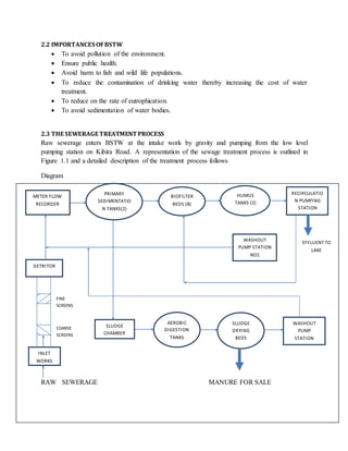
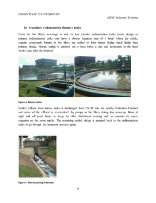
KYAMBOGO UNIVERSITY
FACULTY OF SCIENCE
DEPARTMENT OF CHEMISTRY
AT NATIONAL WATER AND SEWERAGE CORPORATION
BUGOLOBI
BY
HAKIZA ISAAC
12/U/097/BMD/GV
INDUSTRIAL TRAINING REPORT SUBMITTED IN PARTIAL
FULLFILLMENT FOR THE AWARD OF A BACHELORS
DEGREE IN ENVIRONMENTAL SCIENCE TECHNOLOGY
AND MANAGEMENT
MAY 2014-AUGUST 2014
HAKIZA ISAAC 12/U/097/BMD/GV
NWSC-Industrial Training
ii
DECLARATION
I HAKIZA ISAAC DECLARE THAT THIS REPORT CONTAINS A TRUE RECORD OF
ALL THE ACTIVITIES AND WORK I WAS INVOLVED IN DURING MY INDUSTRIAL
TRAINING AT NATIONAL WATER AND SEWERAGE CORPORATION BUGOLOBI
KAMPALA.
SIGN ………………………….
DATE ………………………….
iii
APPROVAL
This report has been submitted for examination with approval of
……………………………….
MR EKEL ALFERD
NWSC INDUSRIAL TRAINING SUPERVISER
DATE…………………………………
………………………………
MR.OCEN CHARLES
UNIVERSITY SUPERVISOR
DATE………………………………...
HAKIZA ISAAC 12/U/097/BMD/GV
NWSC-Industrial Training
iv
ACKNOWLEDGEMENTS
All things work together for a good and so I would like to thank the almighty God for helping me
complete this industrial training successfully and most of all his protection.
I would like to thank my university supervisor for guiding me
I would wish to extend my sincere thanks to the entire management of NWSC for giving me this
great privilege of training with them.
I would like to thank all of the staff members I worked with including Mr. Ekel Alfred my
supervisor, Eng. Kwitonda Angello, Mr. Malambala Enos , Eng. Ocen Alfred for their guidance
technical and practical touch of the training.
In the same way my thanks and prayers go to my mother Mrs.Nizey’Imana Kellen for the
financial support, guidance and advice and the same goes to Mr. Kaguliro Ronald my big brother
for his financial support.
I can’t forget my very own sister Nizey’Imana Dorah for being there for me, supporting me,
comforting me and most of all being a big sister.
Special thanks go to Mr. Kaguliro Peter my uncle and my big cousin Doreen Kamukama for
being there for me especially accommodating me and financially supporting me.
I would like to thank my friends that I trained with Nakyanja Philomera, Adongo Pauline, Nyeko
Daniel, Bonabantu Lawrence for supporting me during the training.
v
TABLE OF CONTENTS
DECLARATION ................................................................................................................................... ii
APPROVAL........................................................................................................................................ iii
ACKNOWLEDGEMENTS ......................................................................................................................iv
PREFACE...........................................................................................................................................ix
ACRONYMS........................................................................................................................................x
CHAPTER ONE....................................................................................................................................1
1.0 NATIONAL WATER AND SEWERAGE CORPORATION.....................................................................1
1.1 BACKGROUND INFORMATION OF NATIONAL WATER AND SEWERAGE CORPORATION:..............1
1.2 HISTORY OF THE URBAN WATER AND SEWERAGE SUB-SECTOR:...............................................1
1.3 VISION ..................................................................................................................................2
1.4 MISSION................................................................................................................................2
1.5 QUALITY POLICY.....................................................................................................................2
1.6 CORPORATE CORE VALUES.....................................................................................................2
1.7 NATIONAL WATER AND SEWERAGE CORPORATION STRUCTURE...............................................2
1.8 OBJECTIVIES OF INDUSTRIAL TRAINING...................................................................................3
CHAPTER TWO ...................................................................................................................................4
2.0 BUGOLOBI SEWERAGE TREATMENT PLANT.....................................................................4
2.1 BACKGROUND INFORMATION................................................................................................4
2.2 IMPORTANCES OF BSTW........................................................................................................5
2.3 THE SEWERAGE TREATMENT PROCESS....................................................................................5
2.4 MANAGEMENT AT THE PLANT..............................................................................................10
CHAPTER 3.......................................................................................................................................12
3.0 SEWER NETWORK...............................................................................................................12
3.1 MAINTENANCE WORKS DONE ON THE SEWER NETWORK ......................................................13
3.2 COMMON BLOCKAGE MATERIALS.........................................................................................14
3.3 PLUMBING RODS .................................................................................................................14
3.4 UNBLOCKING SEWER PIPES ..................................................................................................15
HAKIZA ISAAC 12/U/097/BMD/GV
NWSC-Industrial Training
vi
CHAPTER 4.......................................................................................................................................17
4.0 LUBIGI LABORATORY...............................................................................................................17
4.1 QUALITY CONTROL..................................................................................................................17
4.2. CHEMISTRY LABORATORY.......................................................................................................18
4.2.1 THE EQUIPMENT USED IN THE CHEMISTRY LABORATORY....................................................18
4.2.2 COD TEST (CHEMICAL OXYGEN DEMAND)...........................................................................19
4.2.3 BOD (BIOLOGICAL OXYGEN DEMAND)................................................................................20
4.2.4 TSS AND COLOR................................................................................................................20
4.2.5TOTAL PHOSPHATES...........................................................................................................20
4.2.6 TURBIDITY ........................................................................................................................20
4.2.7 ALKALINITY.......................................................................................................................20
4.2.8 HARDNESS........................................................................................................................20
4.3.0 BIOLOGY LABORATORY.........................................................................................................21
4.3.1FEACAL COLIFORMS...........................................................................................................21
4.4.0 NATIONAL WATER AND SEWERAGE CORPORATION CENTRAL LABORATORY....................22
CHAPTER 5.......................................................................................................................................24
5.0 LUBIGI SEWERAGE TREATMENT PLANT.....................................................................................24
5.1 BACKGROUND INFORMATION..............................................................................................24
5.3 THE SEWERAGE TREATMENT PROCESS..................................................................................24
5.4 TREATMENT PROCESS..........................................................................................................26
CHAPTER SIX ....................................................................................................................................30
6.1. SWOT ANALYSIS FOR NATIONAL WATER AND SEWERAGE COOPERATION..................................30
6.1.1. STRENGTH .......................................................................................................................30
6.1.2. WEAKNESSES...................................................................................................................31
6.1.3. OPPORTUNITIES...............................................................................................................31
6.1.4. THREATS..........................................................................................................................31
6.2 CHALLENGES ...........................................................................................................................32
CHAPTER SEVEN...............................................................................................................................33
7.0 RECOMMENDATIONS..............................................................................................................33
7.1 TO THE ORGANISATION........................................................................................................33
7.2 TO THE UNIVERSITY .............................................................................................................33
7.4 GUIDANCE TO STUDENTS .....................................................................................................34
vii
REFRENCES.......................................................................................................................................35
APPENDICES.....................................................................................................................................36
HAKIZA ISAAC 12/U/097/BMD/GV
NWSC-Industrial Training
viii
TABLE OF FIGURES
FIGURE 1:SCREENING ...........................................................................................................................................................................6
FIGURE 2:SETTLING TANK .....................................................................................................................................................................7
FIGURE 3:FILTER BEDS ..........................................................................................................................................................................7
FIGURE 4:HUMUS TANKS ......................................................................................................................................................................8
FIGURE 5:STREAM JOINING NAKIVUBO..................................................................................................................................................8
FIGURE 6:DIGESTION TANKS..................................................................................................................................................................9
FIGURE 7:DRYING BEDS ......................................................................................................................................................................10
FIGURE 8:MAP OF SEWER ZONNING.....................................................................................................................................................12
FIGURE 9:SEWER BLOCKAGES..............................................................................................................................................................13
FIGURE 10:WORKING EQUIPMENT.......................................................................................................................................................14
FIGURE 11:PLUMBING RODS...............................................................................................................................................................14
FIGURE 12:MANHOLEAND ABLOCKAGE..............................................................................................................................................15
FIGURE 13:RODING METHOD ON NAGURU HOSPITAL .......................................................................................................................16
FIGURE 14:TABLEOF LABORATORY EQUIPMENT...................................................................................................................................19
FIGURE 15:NEMASTANDARDS ..........................................................................................................................................................23
FIGURE 16:TREATMENTPROCESS OF LUBIGI TREATMENT PLANT ..........................................................................................................25
FIGURE 17.ADETAIL OF THEPROCESSES THATTAKE PLACEIN FACULTATIVEPONDS................................................................................29
ix
PREFACE
This report illustrates the work covered during my industrial training period from 26th May 2014
to 21st July 2014 with NWSC in particular: 5 weeks in Bugolobi Sewerage Treatment, 1week in
Lubigi Treatment Plant, 1 week with the sewer network team and 2 weeks in the laboratory.
The report indicates the various activities I carried out during the training. This was mainly a
practical touch. It involved unblocking blocked manholes, surveying for new sewer connections,
carrying out laboratory tests for different samples of waste water.
It also gives an insight into the experience I have gained while training with the project
and how I have benefited from it, and has also helped me to relate the theory studied at the
university to the actual situation outside in the field and to have it put into practice. In addition,
this report aims at suggesting some recommendations to the project as far as its objectives are
concerned, and also to my institution of learning-Kyambogo University. It also illustrates all that
I have covered during the training period.
HAKIZA ISAAC 12/U/097/BMD/GV
NWSC-Industrial Training
x
ACRONYMS
NSWC: NATIONAL WATER AND SEWERAGE CORPORATION
BSTW: BUGOLOBI SEWERAGE TREATMENT WORKS
DO: DISOLVED OXYGEN
COD: CHEMICAL OXYGEN DEMAND
BOD: BIOLOGICAL OXYGEN DEMAND
EC: ELECTRICAL CONDUCTIVITY
TSS: TOTAL SUSPENDED SOLIDS
LSTP: LUBIGI SEWERAGE TREATMENT PLANT
1
CHAPTER ONE
1.0 NATIONAL WATER AND SEWERAGE CORPORATION
1.1 BACKGROUND INFORMATIONOFNATIONALWATERAND SEWERAGE CORPORATION:
NWSC is a utility parasternal 100% owned by the government of Uganda. It was established in
1972 under decree no. 34 following recommendation by WHO. The mandate of the corporation
as defined in NSWC statute of 1995 section 5 i, is to operate and provide water and sewerage
service in areas entrusted to it a sound communication and viable basis.
The NWSC operations were initially in three towns of Kampala, Jinja, and Entebbe. In 1988,
four additional town of Mbale, Tororo, Masaka and Mbarara were handed over to NWSC by
then water development department now known as Directorate of Water Development DWD.
This was after completion of the International Development Agency IDA financed rehabilitation
program
In November 1995, the corporation was handed over to NWSC statute. In 1997, the town of
Kasese and Fort Portal were handed over to NWSC following a successful rehabilitation
financed by the German Government.
In April 1999, the town of kabala was handed over to NWSC as a prerequisite to the
rehabilitation financed by the German Government. The total number of towns currently served
by the NWSC are twenty two viz Kampala, Jinja, Njeru Entebbe, Tororo, Mbale,
Masakambarara, Masindi, Hoima, Lugazi, Malaba and Mukono. These represent the large Urban
Centers With in Uganda.
1.2 HISTORYOF THE URBANWATERAND SEWERAGESUB-SECTOR:
The growth of the Urban Water Sub-sector can be summarized as follows: In the 60's, the water
systems were supply driven with plans agreed upon with the municipal councils.
At this time, the investment funds were available and there was relative efficiency with an
optimum population to serve.
The 70's and early 80's were characterized by rundown water and sewerage systems with very
little maintenance. From the mid 80's, there was a drive towards the rehabilitation of the water
supply and sewerage systems.
HAKIZA ISAAC 12/U/097/BMD/GV
NWSC-Industrial Training
2
The 90's have been characterized by rehabilitation and expansion of both water and sewerage
systems. In the later part of the 90's, there was a drive towards efficiency and performance
enhancement of the sector
NWSC VISION AND MISSION
1.3 VISION
To be the symbol of excellence in the provision of water and sewerage in Africa. When it was
analyzed it was concluded to be
“TO BE THE SYMBOL OF EXCELLENCE AMONG WATER UTILITIES IN THE
WORLD”
1.4 MISSION
To provide our customers with affordable water and sewerage services in a customer oriented
highly professional, commercially viable and environmental friendly manner. This resulted into a
conclusive mission
“TO PROVIDE EXCELLENT WATER AND SEWERAGE SERVICES TO OUR ESTIMED
CUSTOMERS AT A FAIR AND REASONABLE COST”.
1.5 QUALITYPOLICY
NWSC Kampala water shall contribute to national development by provision of quality water
and sewerage services to satisfy her esteemed customers and stakeholders through efficient
service delivery, continual improvement and expansion of infrastructure in an environmentally
friendly manner.
1.6 CORPORATE CORE VALUES
i) “The customer is the reason we exist” this underpins the value NWSC attaches to its
customers. without customers to serve, there would be no NWSC. Without customers paying
their bills, NWSC would not be able to offer its services.
ii) “Water is life, sanitation is Health” this underscores the importance the corporation has for
life and the role water and sanitation play in society.
1.7 NATIONALWATERAND SEWERAGE CORPORATIONSTRUCTURE
NWSC is divided into 7 different divisions
1. Institutional development and External services
2. Planning and Capital Development
3. Commercial and customer services division
4. Finance and accounts division
3
5. Internal audit division
6. Management services division
7. Engineering services division
1.8 OBJECTIVIES OFINDUSTRIALTRAINING
The primary objective of industrial training is for the student to gain practical work experience
and to be able to see theory in practical.
Industrial training is geared to developing skills and knowledge
Learn accepted safety practices in the industry.
To equip staff with skills, knowledge and attitudes required to perform their individual tasks
satisfactory.
Understand that the problems encountered in the industry are rarely have unique solutions, and
there is need to gain experience necessary for selecting the optimal solutions from the many
options.
HAKIZA ISAAC 12/U/097/BMD/GV
NWSC-Industrial Training
4
CHAPTER TWO
2.0 BUGOLOBI SEWERAGE TREATMENT PLANT
2.1 BACKGROUND INFORMATION
Bugolobi sewerage treatment works BSTW was constructed prior 1940 and was subsequently
extended during the periods 19561958 and 19681978.
It is located South East of Kampala, Bugolobi Sewerage treatment works is the biggest sewerage
treatment plant in Uganda. This low lying sewerage treatment works altitude 1160m above sea
level covers an area of approximately 15 hectares 37bacres, which is occupied by both the
currently operated Bugolobi STW and the older disused sewerage treatment facilities.
The BSTW which was designed to handle a hydraulic flow capacity of 33,000m3day with a Dry
Weather Flow DWF of 16000m3day receives an average of 12500m3day dry weather flow and
an average wet weather flow of 15000m3deform the existing 135km of the sewerage line
network which covers approximately 8% of Kampala households. From the sewer lines, the
sewerage flows by gravity via siphons and also through three pumping stations (the low level
pumping station), East Bugolobi P.S and Kibira road P.S to the plant inlet. In addition, the plant
receives about 105 m3|day of seepage from cesspool emptier which in two pounds at the
treatment works.
The treatment plant receives an estimate of 500 g BOD / l and can be said to averagely achieve a
treatment efficiency of 65%. The plant employs a conventional treatment system comprising of
preliminary treatment and a biological treatment. The preliminary treatment comprises of
screening through two screens a 40 mm Coarse and a 20 mm fine screen, grit removal I a grit
chamber and primary settlement in 02 sedimentation basins with a total volume of 3,764m3. The
biological treatment comprises of filtration in 08 trickling filters with an active depth of 2m and
total surface area of 7,176 m2. The process is followed by further settling in the 02 clarifiers with
a total volume of 3,764m3. The final effluent may be recycled back for further treatment by use
of 02 recirculation pump or meeting the expected effluent quality, it will be discharged into
Nakivubo channel to join the Murchison Bay via the Nakivubo swamp, where tertiary treatment
of the effluent is further achieved.
The plant also consists of six open sludge digesters where sludge produced at the site is subjected
to anaerobic digestion at ambient temperature before dewatering on 56 sludge drying beds. The
dried sludge is collected and reused by farmers.
5
2.2 IMPORTANCES OFBSTW
 To avoid pollution of the environment.
 Ensure public health.
 Avoid harm to fish and wild life populations.
 To reduce the contamination of drinking water thereby increasing the cost of water
treatment.
 To reduce on the rate of eutrophication.
 To avoid sedimentation of water bodies.
2.3 THE SEWERAGE TREATMENT PROCESS
Raw sewerage enters BSTW at the intake work by gravity and pumping from the low level
pumping station on Kibira Road. A representation of the sewage treatment process is outlined in
Figure 1.1 and a detailed description of the treatment process follows
Diagram
RAW SEWERAGE MANURE FOR SALE
METER FLOW
RECORDER
DETRITOR
INLET
WORKS
WASHOUT
PUMP STATION
NO1
RECIRCULATIO
N PUMPING
STATION
PRIMARY
SEDIMENTATIO
N TANKS(2)
BIOFILTER
BEDS (8)
HUMUS
TANKS (2)
WASHOUT
PUMP
STATION
SLUDGE
CHAMBER
AEROBIC
DIGESTION
TANKS
SLUDGE
DRYING
BEDS
EFFLUENT TO
LAKE
FINE
SCREENS
COARSE
SCREENS
HAKIZA ISAAC 12/U/097/BMD/GV
NWSC-Industrial Training
6
2.3.1.PRELIMINARY TREATMENT
When raw sewerage is delivered to the treatment works it contains an appreciable amount of
floating materials (such as wood, paper, rugs, plastics and fecal material) as well as heavier
solids such as grit and large suspended. In order to prevent damage to mechanical equipment
such as pumps as well as blockages of pipes and valves, these solids have to be removed at an
early stage in the treatment process and disposed of by burning or burying. To achieve this,
sewerage is simply passed through a series of screens and strainers. This is known as preliminary
treatment and generates small quantities of residues. At BSTW, sewerage is passed through two
sets of hand raked coarse screens and fine screens spaced at 40mm and 20mm/cc respectively. It
is then sent to a detritus basin which allows grit, sand and pebbles and heavier inorganic particles
to settle out, these are sent to the sump by a rotating paddle and grit is removed from this sump
by a grit pump for final disposal by burring. The screened settled sewerage gravities through a
measuring flume which records the instantaneous rate of flow (flow range usually from 0-600
liters/second). Sewerage that has been subjected to preliminary treatment still contains a high
concentration of settleable solids and primary sedimentation tanks are used to remove these.
Figure 1: Screening
7
2.3.2.PRIMARY TREATMENT
BSTW uses two circular 28.2 diameter sedimentation tanks with a surface area of 625m2 and a
retention volume of 1882m3 each. The tanks have a sidewall depth of 2.44 with a floor slope of
12%. The optimum retention time in each tank is two hours. Primary treatment generates a large
amount of primary sludge that is removed periodically from the bottom of the sedimentation
tanks together with minor quantities of oil, grease, and scum skimmed from the top of the tanks.
;This step also results in the separation of waste water into two different streams, each of which
goes to different secondary treatment step.
Figure 2: Settling Tank
2.3.3.SECONDARY TREATMENT
a) Biofiltration
Settled sewerage from primary treatment is passed through filter media (circular beds eight in
number consisting of stone medium of varying sizes and shapes) where it receives treatment
biologically by micro organisms up on the stone media, breaking down the dissolved organic
particles in the presence of atmospheric oxygen to form stable organic compounds.
Figure 3: Filter beds
HAKIZA ISAAC 12/U/097/BMD/GV
NWSC-Industrial Training
8
b) Secondary sedimentation (humus) tanks
From the bio filters, sewerage is sent to two circular sedimentation tanks (same design as
primary sedimentation tanks only have a shorter retention time of 1 hour) where the stable,
organic compounds formed in bio filters are settled to form humus sludge much lighter than
primary sludge. Humus sludge is pumped out a least twice a day and recirculate to the head
works (just after the detritor)
Figure 4: Humus tanks
Settled effluent from humus tanks is discharged from BSTW into the nearby Nakivubo Channel
and some of the effluent is re-circulated by pumps to bio filters during low sewerage flows at
night and off peak hours to keep the filter distributors rotating and to maintain the micro
organism on the stone media .The remaining settled sludge is pumped back to the sedimentation
tanks to go through the treatment process again.
Figure 5: Stream joining Nakivubo
9
2.3.4 SLUDGEDIGESTION
Due to the physical-chemical processes involved in sewerage treatment, the sludge stream tends
to concentrate heavy metals and poorly biodegradable trace organic compounds well as
potentially pathogenic organisms (viruses, bacteria etc) present in sewerage. Untreated sewerage
sludge has relatively high levels of disease causing micro- organisms (pathogens) and is
decomposable (or unstable). The unstable nature of untreated sewerage sludge can generate
ordors and makes it attractive to disease carrying vectors such as insects, rodents, and birds.
Therefore, further treatment of sludge is conducted to reduce pathogen levels and vector
attraction.
BSTW possesses infrastructure for anaerobic sludge digestion. Primary and secondary (humus)
sludge is broken down biologically by bacteria action in six circular tanks. The process takes 20-
30 days depending on the weather (the hotter the temperature, the shorter the retention time) and
is divided into two stages: acidic stage (organic solids broken down biologically to form organic
acids which kill off certain species of bacteria depressing the pH) giving an alkaline stage
(organic acids broken down to give stable compounds like phosphate, nitrates etc). the latter
process also results in the production of gaseous by products including water, carbon dioxide,
ammonia, carbon monoxide and methane or biogas a source of fuel that is currently un-tapped at
this STW.
Figure 6: Digestion tanks
Thickened stable sludge is then pumped to drying beds after removal (decanting) of water from it
during drying.
HAKIZA ISAAC 12/U/097/BMD/GV
NWSC-Industrial Training
10
2.3.5 DRYING
This takes place on 56 open concrete slabs on which are laid half round drainage tiles over which
are placed stones and coarse sand filter media for draining off sludge liquor. Each drying bed has
a capacity to dry about 30m3 of wet digested sludge leaving behind a 75mm thick dried sludge
cake. The sludge cake is sold mainly for horticultural use as a low quantity high quality organic
fertilizer.
Figure 7: Drying beds
2.4 MANAGEMENT AT THE PLANT
This electrical maintenance is mainly done on the settling tank scrapers. These settling tank
scrapers are run by motors. For every motor you have a starter and then a slowdown gear box or
pulley system. These motors power a gear box which then rotates a wheel thus moving the
scrapers. The gear box is usually used to step down the rpm (revolutions per minute) of the
motor. The starter is basically the same as the control panelbox i.e. it has the usual starters,
relays (4 control of voltage) contractors and other electrical parts to start and control the motor
movement.
However, the bio filter arms are hydraulicallywater pressure driven and so they don’t require
electricity for use i.e. anytime that there’s water flowing at a specific pressure, the arms move.
There is therefore little to no maintenance required for these. Only physical unblocking of the
stone bed and replacement of fallen stones is done when necessary.
The low level booster station has a duty pump with a lip ring motor and this pump requires
maintenance in case of break down. However no stand by pump is available so in the case of a
break down there’s no bail out.
11
It is important to note however that the type of maintenance done is more corrective than
preventive because the machines are so old that their working time should be maximized and
maintaining before any break down will often waste valuable working time.
An inspection of the whole plant is done by different people at different times, different days and
different people.
Samples are picked at every point or stage of the plant; they are then taken to the central lab to
test for the effectiveness of the plant.
HAKIZA ISAAC 12/U/097/BMD/GV
NWSC-Industrial Training
12
CHAPTER 3
3.0 SEWER NETWORK
The Kampala sewer networking is comprised of a pipe network of about 135km long with pipe
sizes ranging from 110mm up to 675mm diameter. Pipe materials include clay asbestos, concrete
and most recently PVC pipes 56% of the sewer lines were built in the 1940s with altogether 86%
built within 1940 and 1969 and only 14% installed after 1969.
This sewer network is divided into four main sections/ districts for easy maintenance namely;
Bugolobi, Katwe, Central (i.e. dealing with CBD) and Kololo. Each district is assigned a team
responsible for rectifying any network failures and ensuring proper operation. There’s also a
PPM team which operates a jetting truck/cesspool truck and together with the maintenance team
preventative maintenance schedule. A new connection and network development team is also
under operation and this team is responsible for carrying out a new sewer connection as well as
all network upgrades.
The other areas of Kampala not serviced by the sewerage treatment plants have their sewerage
directed to treatment lagoons’ which release their effluent into Nakivubo swamp and channel
before deposition into Lake Victoria. The sate light treatment systems /lagoons were previously
managed locally but are now under NWSC’s jurisdiction.
Important to note in the sewer network set up are the following; the recommended slope for
sewerage pipe lay out is 1inch to 6metres i.e. one inch drop for every 6m horizontal distance. In
addition for the manholes off the roads in areas where aesthetics its note a big concern it is
recommend that manholes protrude about 1ft above the ground level to prevent storm water
runoff from entering the manhole. However, manhole covers are water and air tight so this is not
a big concern. As regards cover depth, for manholes on the road the minimum cover depth is
1.5m. In addition, sewers are always placed deeper than the water lines to avoid water
contamination in case of sewer leak. There is also no maximum depth of manhole given for
construction so precautions should be taken to ensure that the different entrance
guidelines/procedures given for different manhole depths are adhered to by maintenance teams.
In fact, the deepest manhole present in Kampala sewer network is about 17m deep.
Figure 8: map of sewer zonning
13
3.1 MAINTENANCE WORKS DONE ONTHE SEWERNETWORK
During my training my group mainly focused on the central region. We had to report to certain
points that had problems or blockages and solve them.
Some of the challenging areas were |”Jinja Road next to shoprite lugogo”
Figure 9: Sewer blockages
These are some of the methods we used to unblock sewer blockages.
i)unblocking sewers using the rodding method: the rodding method/use of wires is used in
conjunction with a motor which rotates the wires/rod causing them to move further into the
piping system and collect any cloth or rags causing the blockages.
ii) unblocking sewers using the jetting truck/flushing method: this involves flushing of the
sewers with high pressure water in order to force the blockages to move further down into the
network. It is usually done when unblocking using the rodding method has failed and plays a key
role in the de silting of sewers.
iii) other maintenance works include replacement of manhole covers as well as replenishment of
the concert manhole benching.
iv) inspection of different manholes or people with overflows calls the management.
l
HAKIZA ISAAC 12/U/097/BMD/GV
NWSC-Industrial Training
14
Figure 10: working equipment
3.2 COMMONBLOCKAGE MATERIALS
Toilets and toilet pipes get blocked when people put the wrong things down the toilet. Some of
the things which should never be put down the toilet are food scraps, paper, rags, cans, bottles,
grease and fat.
Wastewater pipes from sinks, basins and laundry tubs can get blocked if people put food waste,
especially tea leaves, hot fat and other rubbish down them. If hot fat is poured down an outlet
pipe, it will set in the pipe when it cools and cause a blockage.
In addition to blockages caused by these materials, main sewer pipes can get blocked in other
ways, for example, tree roots growing into the pipe joints and soil blocking the pipe when it is
broken by vehicle traffic.
3.3 PLUMBING RODS
Plumbing rods are pieces of equipment used to remove most blockages from sewer pipes. However, when
sewer pipes are broken plumbing rods are not effective and the damaged pipe must be replaced.
The rods screw together so that they can be made as long as needed. They have different kinds of endings to
help remove the blocking objects.
Figure 11: Plumbing rods
15
To unblock the sewer pipe it is important to find an inspection opening (IO) below the blockage and push
the rods up the pipe to the blockage.
Always remember which way the rods and endings have been screwed together and always twist the rods
in the same direction.
If this is not done, the rods are likely to become unscrewed and be left in the sewer pipe. This will create a
worse problem because the rods will also block the pipe. If this happens it will probably be necessary to
dig up the sewer pipe and break it to unblock the pipe and get the rods back. This would have to be done
by a licensed plumber.
3.4 UNBLOCKING SEWERPIPES
The larger sewerpipeshave manholessetinthemallowingaccesstothe pipe.Theyare oftenabouta
meterundergroundandare large boxeswhichusuallyhave wallsmade of concrete.The pipe opensinto
the box on one side andstarts again onanotherside.
The lids,whichare made of metal,canbe liftedtoallow someone tolookdownintothe sewertosee if
there isevidence of ablockage,forexample,wastewaterbuild-upinthe manhole.
Figure 12: Manhole and a blockage
A blockage inthe sewerpipe cancause the wastewatertobuild-upinthe manhole.
Extreme care must be taken when openingthe lidsof sewerpipesas poisonousand explosive gases
can buildup in these pipes.
Before attemptingtounblockasewerpipe it isimportanttoremember:
 Before making an inspection, always wait several minutes to allow any poisonous or
explosive gases to escape
 Never smoke while doing this work
 Never do this work alone
HAKIZA ISAAC 12/U/097/BMD/GV
NWSC-Industrial Training
16
 Never enter a manhole without proper safety measures. It may be necessary to wear
breathing equipment or to ventilate (add fresh air) to the manhole and sewer pipe. The
gases in it can kill.
It isalwayssafesttocheck withthe Water Authority,the local governmentEHOorsupervisorbefore
openingthe lidorenteringthe manhole.
If there are no manholes,thenthere willbe IOswithcementorplasticcapson the pipes.There maybe a
concrete box aroundthe inspectionopening.Sometimestheseare below the groundandare not easyto
find.Itmay be necessarytodig to findthem.
It isa goodideato getthe sewerpipe plansforyourcommunitysothat youcan refertothe plans
before startingtodig.
Figure 13: Roding method on Naguru HOSPITAL
17
CHAPTER 4
4.0 LUBIGI LABORATORY
4.1 QUALITY CONTROL
The quality and sewerage services department consists of a quality control (QC) section also
located at BSTW which ensures that all sewerage effluent is satisfactory and meets the required
standards. According to the section, after the various sewerage treatment processes have been
completed (preliminary, primary and secondary) the final sewerage effluent has a BOD range of
20-90mg/l and a TSS range of 30-60mg/l values not far off the National Environmental
Management Authority (NEMA) standards of BOD and TSS of 50mg/l, considering the high
dilution factor of the receiving water in the Nakivubo Channel and later to Lake Victoria.
In addition, the QC section also conducts routine tests including following the process in BSTW
efficiency. Nevertheless, at present, the lab is not equipped to handle and/ or test for other
important components of sewerage that have the ability to affect human health and the
environment. For example, the lab does not possess a mass spectrometry machine. (Atomic
Absorption Spectrometry/Gas Chromatography) to test for heavy metals found in sewerage and
sludge (copper, zinc, mercury, lead). Although predominantly domestic sewerage is received,
these components tend to be present and the sewerage treatment process employed in Bugolobi
cannot remove them. Additionally, although nutrients, phosphates and nitrogen compounds are
routinely monitored, their removal is minimal since removal of these compounds can only be
achieved via tertiary treatment, which the plant does not employ and although BSTW believe
tertiary treatment is achieved in Nakivubo swamp a natural purifier, the levels of purification are
not clear.
The central lab carries out tests for water and waste water samples from different parts of the
country. The central lab is comprised of the chemical and the biological lab. The chemical
laboratory deals with chemical parameters while the biology lab deals with the micro-biological
tests and aspects.
NETWORKING IN THE LAB
Samples are picked from different points both clean and waste water. We sampled some points
of sewer water: Kayunga stream, Kayunga upstream, Kansanga stream, Fire brigade, Agakhan,
Agakhan YMCA up, Agakhan down. Clean water is also picked for sampling.
HAKIZA ISAAC 12/U/097/BMD/GV
NWSC-Industrial Training
18
4.2. CHEMISTRY LABORATORY
4.2.1 THE EQUIPMENT USED INTHE CHEMISTRYLABORATORY
Laboratory equipment Purpose of the equipment
DR 5000
Spectrophotometer
It works by using the light absorption to give the
light intensity amount for different chemical
parameters.
COD Reactor To allow the COD reaction time
DO meter For measuring dissolved oxygen in samples
EC Meter and probe To measure the electro- conductivity of the samples
oven
For drying different samples
Ph meter For measuring pH of smples
19
Turbid meter For measuring turbidity
Incubator (cold) For the 5day BOD reaction time and preserving other
samples
Water distiller To distill water
Aerator For aeration of water for the BOD test
Autoclave For sterilization TP(Total phosphates)
Figure 14: Table of laboratory equipment
The following are some of the tests done in the chemistry laboratory with their procedures.
4.2.2 COD TEST (CHEMICALOXYGENDEMAND)
Add 2.5ml of potassium dichromate to a small round flask. Then add 2.5ml of the sample to it.
Finally, add 3.5ml of sulphuric acid to this sample. Note that you have to set a blank by also
setting up a distilled water sample set. If the COD is high greater than 500 to greater than 700,
the mixture will immediately turn green.
HAKIZA ISAAC 12/U/097/BMD/GV
NWSC-Industrial Training
20
You the place them in the COD reactor for 1hour, then you leave them to cool and so proceed
with the reading of the results using the spectrometer.
4.2.3 BOD (BIOLOGICAL OXYGENDEMAND)
The BOD test is basically used to determine the amount of active biomass/bio-organisms present
by determining the amount of dissolved oxygen DO present in the solution. The test is done for a
duration of 5days during which the samples are placed in a cold incubator (set to about20c)
allowing the micro-organisms present to feed on the dilution mixture and thus reducing/taking up
the dissolved oxygen present in the solution.
4.2.4 TSS AND COLOR
These are both checked using the spectrophotometer after being zeroed with distilled water
4.2.5TOTALPHOSPHATES
The sample amount is taken depending on its concentration but has to add up to 25ml whether
diluted or not. To the sample add 1ml of sulphuric acid and 5ml of potassium persulphate. Place
it in the autoclave for digestion and leave the samples there until the autoclave for digestion and
leave the samples there until the autoclave hisses. On hissing, turn it off and time for 30 minutes
before opening so as not to come into contact with the stream. Then remove the samples and add
3ml of mixed reagent and 1ml of ascorbic acid. You can now take the spectrophotometer reading
of the sample TP
4.2.6 TURBIDITY
Turbidity is an expression of optical property that causes light to be scattered and absorbed rather
than transmitted in straight lines through the sample. Turbidity is tested using a turbid meter and
probe is placed into the mixture and readings taken.
4.2.7 ALKALINITY
Alkalinity is used as an indicator of the concentration of carbonates, bicarbonates and hydroxide
contents. We add 25ml of sample to a conical flask. Then 3-5 drops of mixed indicator is added
to a sample. Then titrate with Hall until the end point is reached. The mixture turns from blue to
pink
4.2.8 HARDNESS
Place 25ml of sample in a conical flask; add 3-5 drops of buffer indicator followed by a small
amount of hardness indicator. Then titrate using EDTA until the mixture turns from purple to
blue.
COD IS PREFERED TO BOD
The fact that COD measures both the organic and inorganic, it covers both the degradable and
non degradable decomposition while BOD deals with only organic degradable.
21
NB: The higher the total suspended solids the higher the COD and BOD, microorganisms tend to
attach to suspended solids in water.
COD takes a shorter time approximately 3hours compared with 5 days of BOD giving
allowances for correction at the plant.
4.3.0 BIOLOGY LABORATORY
In the biology laboratory both water and waste water are analyzed mainly for coliforms.
4.3.1FEACALCOLIFORMS
Principle
A volume of 100ml of the sample is filled through a membrane composed of cellulose esters to
concentrate the microbes if any present.
All bacteria present are retained on the surface of the membrane which is then incubated face
upwards on a differential selective medium. Lauryl sulphate broth is used it contains
phenolpthaline.
Method validation
Samples with high suspended solids have interference with colonial growth and enumeration
hence has to be diluted.
Sampling and preservation
Samples must be collected in sterile, glass or plastic bottles with stoppers, these bottles are
specially prepared with sodium thiosulphate to deechlorinate the water so that there is no further
disinfection. Samples may be analyzed from the field or transported to the laboratory in a cool
box with ice blocks.
Samples not analyzed immediately have to be refrigerated
HAKIZA ISAAC 12/U/097/BMD/GV
NWSC-Industrial Training
22
Procedure
Membrane pads were placed into petri- dishes using forceps and using pipette 2.5ml of sulphate
broth were transferred onto the pads in the petri dishes. A membrane filter is placed into the
filtration assembly on the vacuum flask using sterile forceps and aseptic methods (sterilized
gridded face of filter facing upwards) A measured volume of the sample is diluted through the
filtering unit. When all the poured volume is filtered, the filter membrane is removed and placed
with gridded side upper most on the pad soaked in excess of medium (ensuring that no air bubble
was trapped between pad and membrane)
The petri dish lid is placed upper most onto the petri dish carrier. The carrier with the petri dishes
was placed into an incubator and the incubator lid was replaced.
For total coliforms analysis, samples are incubated at 37 C 0.5C for 12-16 hours. For fecal
coliform analysis, samples are incubated at 44C 0.5Cfor 12-16 hours.
After incubation the samples are analyzed under a microscope.
4.4.0 NATIONAL WATER AND SEWERAGE CORPORATION CENTRAL
LABORATORY
NATIONAL STANDARDS FOR WASTEWATER DISCHARGE – NEMA STANDARDS
Parameters Units
National Standards
4 effluents discharge.
(Maximum Permissible)
Temperature OC 20-35
Ph -- 6.0 – 8.0
Electrical Conductivity S/cm 1500
Colour PtCo 500
Turbidity NTU 300
Total Dissolved Solids mg/L 1200
Total Suspended Solids mg/L 100
Alkalinity: total as CaCO3 mg/L 800
Chloride mg/L 500
Aluminium: Residual mg/L 0.5
Iron: total mg/L 10.00
Orthophosphate mg/L 5.0
Sulphide mg/L 1.0
Total Phosphorus mg/L 10.0
Sulphate mg/L 500
Ammonia-N mg/L 10.0
23
Total Nitrogen mg/L 20.0
Nitrate: NO3
- mg/L 10.0
BOD5 mg/L 50
COD mg/L 100
Arsenic mg/L 0.2
Cadmium mg/L 0.1
Copper mg/L 1.0
Lead mg/L 0.1
Zinc mg/L 5.0
Nickel mg/L 1.0
Cobalt mg/L 1.0
Chromium: hexavalent mg/L 0.05
Chromium: total mg/L 1.0
Oil & Grease mg/L 10.0
Faecal Coliforms CFU/100mL 5,000
Total Coliforms CFU/100mL 10,000
Figure 15: NEMA standards
Source: NEMA
HAKIZA ISAAC 12/U/097/BMD/GV
NWSC-Industrial Training
24
CHAPTER 5
5.0 LUBIGI SEWERAGE TREATMENT PLANT
5.1 BACKGROUND INFORMATION
The Lubigi plant is part of the Lake Victoria Protection Project (Phase 1) intended to reduce pollution of
Lake Victoria and improve waste water treatment within the city of Kampala in addition to the already
existing Bugolobi Sewerage Treatment Plant.
Lubigi plant has been in operation since 2013 with an addition of cesspool emptiers in early 2014, this
treatment plant uses the biological method of waste water treatment using biological ponds.
The plant is meant to treat 5.4 million litres per day, in addition to piped sewage and waste water from
septic tanks and pit latrines from the city’s informal settlements.
This new plant will serve Kawempe,Bwaise,Katanga, Makerere,Nsooba and surrounding hotspots
including Mulago Hospital and Wandegeya.
Under the Lake Victoria Protection Project (Phase 1),sewerage services will be extended to Katwe and
Makindye Army barracks,as well as rehabilitation of Bugolobi plant.
The sh53b (€15.4m) project is jointly funded by Government of Uganda (€2.5m), Germany (€6m) and the
European Union (€6.9m)
5.2 IMPORTANCESOF LUBIGI SEWAGE TREATMENT PLANT
 Lowest operation and maintenance costs for required treatment efficiency (unskilled labourers
required for cutting grass round the pond and removing scum from the pond surface)
 Greater pathogen removal.
 Flexibility with respect to hydraulic and organic shock loads (over short time intervals)
 Ability to treat a wide variety of wastes (industrial, agricultural, etc.)
 Can be designed for easy alteration of treatment efficiency.
 Easy reclamation of land if later required.
 Algae produced in ponds are a potential for high protein food that can be exploited for fish farmin
5.3 THE SEWERAGE TREATMENT PROCESS
The Lubigi Sewerage Treatment Plant uses both the physical and biological methods of waste water
treatment beginning with the physical then the biological ones.
25
5.3.1DIAGRAM OF LUBIGI SEWAGETREATMENT PROCESS
Figure 16: Treatment process of Lubigi Treatment Plant
OFF SITE
WASTE
WATER
ON SITE
FEACAL
SLUDGE
SCREENING
GRIT
REMOVAL
(2)SEDIMENTATION
TANKS
COVERED
SLUDGE
DRYING
BEDS
SCREW
PUMP
SCREENING
GRIT
REMOVAL
FLOW
MEASUREMENT
FLOW
DISTRIBUTION
(3)ANEROBIC
PONDS
(2)FACULTATIVE
PONDS
FLOW
DISTRIBUTION
FINAL
EFFLUENT
OPEN DRYING
BEDS
HAKIZA ISAAC 12/U/097/BMD/GV
NWSC-Industrial Training
26
5.4 TREATMENT PROCESS
5.4.1 ON SITE FEACAL SLUDGE
This onsite feacalsludge is brought by cesspool emptiers from points around the city like latrines, full
septic tanks, hotels and other points that have waste water that needs to be treated.
5.4.2 OFFSITEWASTE WATER
Off site waste water comes in through the sewer connections to the treatment plant, which is made up of
laid underground pipes from different points like Kawempe and Busia.
5.4.3 SCREW PUMP
The screw pump is made up of two long screws that lift the waste water into the treatment plant from the
lower level, these screw pumps work automatically when the amount of the waste water is enough it is
pumped up.
27
5.4.4 SCREENING
The removal of floating materials (such as wood, paper, rugs, plastics and fecal material) that is
not wanted both from the offsite waste water and the onsite feacal sludge using screens that are
raked like below.
5.4.5 GRIT REMOVAL
Grit which are usually the sand particles that settled at the bottom of the waste water are removed as the
waste water moves through a water channelconstructed to give the waste water enough retention time so
that the grit can settle.
5.4.6 SEDIMENTATIONTANK
Sedimentation tank gives the waste water enough retention time for the suspended particles to settle to the
bottom as sludge which is pumped out into the drying beds.
HAKIZA ISAAC 12/U/097/BMD/GV
NWSC-Industrial Training
28
5.4.7 FLOWMEASUREMENT
This the measuring the amount of waste water that is going to be treated and this measurement is carried
out using two methods either ruler measurement or automatically using a machine directly connected to a
computer.
5.4.8 FLOWDISTRIBUTION
Flow distribution receives the waste water from one point and distributes it into different sections
especially at the anaerobic ponds and facultative ponds.
5.4.9 ANEROBIC PONDS
Anaerobic ponds are used for the treatment of high strength organic wastewater that also contains a high-
suspended solids concentration, e.g. industrial wastewater. They are three in number and placed first in a
series of waste stabilisation ponds before the facultative ponds. In anaerobic ponds, organic matter is
removed by sedimentation and biological digestion by anaerobic bacteria. This produces gases like H2S,
CO2, NH3 and CH4 and soluble nutrients. Sludge is left behind under the waste water.
29
5.4.10 FACULATIVEPONDS
These Facultative ponds are used for BOD and pathogen removal. They can be the first ponds in a series
of treatment ponds or they can be preceded by anaerobic ponds. In these facultative ponds, stabilisation is
brought about by a combination of aerobic, anaerobic and facultative bacteria.
Figure 17. A detail of the processes that take place in facultative ponds
HAKIZA ISAAC 12/U/097/BMD/GV
NWSC-Industrial Training
30
CHAPTER SIX
6.1. SWOT ANALYSIS FOR NATIONAL WATER AND SEWERAGE COOPERATION
6.1.1. STRENGTH
 Dedicated,hardworkingandskilledstaff withvastexperience
 Good customercare
 Highstaff integrity
 Soundinformationtechnologyinfrastructure
 Good billingsystem
 Well establishedinstitutional structuresandsystems
 DecentralizedPolicy(areas,branches,territories)
 Visionaryleadershipatboardand managementlevelsadheringtogoodcorporate governance
principles
 Favorable welfarepolicy,especiallythe medical policy
 ISOcertificationof all areasincludingheadquarters
 Soundfinancial systems
 Well establishedM&Esystems
 Clearand well documentedpolicies
 Existence of asupportive tariff indexationpolicy
There exists a highly facilitated quality assurance system at the same location as the sewerage
treatment works. This consists of a highly equipped laboratory and a dedicated staff which is
important in ensuring that the final effluent being released in to the environment meets the set
standards by NEMA as well as carrying out routine tests to ensure the efficiency of each
treatment stage.
There is also a steady supply of raw sewerage from Kampala central trade district as well as the
surrounding suburbs.
NWSC which is the monitoring body of Bugolobi Sewerage Treatment Works has good
organization structure which help in the smooth running of the plant.
Occupational health and safety is ensured in NWSC the workers themselves are ensured, they are
also given protective gears like rubber gloves and heavy duty gloves for the appropriate work.
The workers are also provided with gumboots. Furthermore the workers have heath talks for
example we had an STDs talk by a specialist, drug abuse all this is vital in occupational health
and safety.
NWSC normally carries out performance appraisal and in addition help them relax and refresh
their bodies physically. They hold competitions in sports for all branches and also participate in
corporate league. This brings about togetherness.
31
6.1.2. WEAKNESSES
 Insufficientfunding,impendingserviceexpansion
 Staff turnover
 HighNon-Revenue Water(NRW) byInternational Standards
 Highlevel of inactive accounts/suppressedaccounts.
 Highdebtage
 The aged infrastructure especiallyaroundKampala
 Inadequate sewerage services
 Intermittedwatersupply/dryzones
 Inadequate assetmanagement
Rampant sewerage spillages due to constant break down in the sewer network. This is mainly
due to blockages due to collection of polyethane bags (Kavera), accumulation of silt with in the
sewer to mention but a few. These put the community at a risk of being affected by the sewerage.
There exists un-renovated infrastructure at the treatment plant in Bugolobi such as sedimentation
tanks which occupy a lot of space which can be utilized for other activities within the plant.
In addition to that the altitude of Kampala city as a whole is not that good, that is to say it is
situated in a series of hills with steep slopes separated by hills varying gradients which makes
sewerage collection and water supply costly.
There is a slow response to emergency cases.
6.1.3. OPPORTUNITIES
Methane gas which is produced at the plant in Bugolobi can be utilized in the production of
energy to supplement the national grid. It can also be used for cooking in homes and industries
which in a long run will reduce on the rate deforestation and air pollution with in the country.
The sludge cake formed in the drying beds can be used as a source of fuel as well as fertilizers
which help to increase on the crop production hence boosting agriculture.
6.1.4. THREATS
Most of the equipment used at the clean water treatment plant is manufactured from outside
Uganda. It therefore takes a long process to procure and also to transport them in to the country.
The population of Kampala that was planned for to use the BSTW has gone beyond planned
therefore the plant is over worked and a new plant may be needed in place to accommodate the
big populations.
HAKIZA ISAAC 12/U/097/BMD/GV
NWSC-Industrial Training
32
6.2 CHALLENGES
Below are some of the challenges I experienced during the training or I was likely to face namely;
There are conditions associated with exposure to sewage which I was working with on a daily basislike;
 Gastroenteritis
 Skin infections
 Eye infections
 Tetanus, Polio, Hepatitis A, Hepatitis B, Hepatitis C
 Respiratory illness
These conditions are likely to strike anyone without vaccination. The good things the staff of the co-
operation are vaccinated and us students we are not which is the biggest challenge.
The bad odur and stench from the sewage was a very big challenge that caused me to be sick for almost
the whole first beginning week but with time I adapted to the smell and had to work under those
conditions.
Lack of protective equipment from the co operation that was very expensive and I had to buy on my own
was one of the biggest challenges since the financial support I had for the training was not enough.
Lack of facilitation from both the university and the co operation like transport, meals and
accommodation was also a big strain on me which was a very big challenge.
Lack of enough practical lessons that gave me a hard time to catch up with the practical work in the field
especially carrying out of laboratory work.
33
CHAPTER SEVEN
7.0 RECOMMENDATIONS
7.1 TO THE ORGANISATION
Concerned authorities should consider garbage collection, dumping and industrial wastes away
from the lake because they end up contaminating the entire lake.
The labor rate should be specified in general depending on the working environment that is to
say staff exposed to heavily contaminated sewage.
Sensitization of the workers about safety and wearing of protective gears should be done
regularly in more understandable languages for example hanging posters in the respective
workplaces for them to appreciate the importance of safety. The NWSC customers should be
informed on how to use the resources they have to avoid so many sewer blockages and bursts in
clean water.
The department concerned should make protective gears available to the staff whenever they are
needed especially gloves, gum boots, helmets this will help to reduce on any accidents. More so
the old equipment should be replaced as soon as they get old to avoid any accidents and
contamination
It is also important that the public assists NWSC in its straggle to prevent the wastage of water
through prompt reporting of leakages and bursts on the pipes and also avoid vandalism of water
supply infrastructure. This can be done by using the toll free number to report to the cooperation
at its call center located at 6th street industrial area.
7.2 TO THE UNIVERSITY
The period scheduled for industrial training is quite short, in relation to the activities and things
to learn and cover in the field. Environmental Science covers a wide range and we actually used
more time than that allocated by the university.
Therefore, my humble suggestion is that the Industrial Training period should be extended to at
least from one to two times throughout the 3 years period of study. Environmental Science
students should be let go for Industrial Training from their first year of study, such that the study
in second year is a compliment to what is covered in the first year.
HAKIZA ISAAC 12/U/097/BMD/GV
NWSC-Industrial Training
34
7.4 GUIDANCE TOSTUDENTS
The students leave the university without guidelines of what they should cover in the field. They
leave the University for Industrial Training with guidelines for Report Writing only, but without
knowing what they are supposed to cover during the training. In such a situation, most of the
students are more likely to engage in activities not applicable with their field during the training.
I suggest that students should be clearly briefed, guided and given a clear description of what
they should cover in the field.
RELATIONSHIP WITH INDUSTRIES/ORGANIZATIONS
The University should try to befriend and collaborate with several Industries and Organizations
in the country. This can be achieved by joining/forming associations with them, giving them
market for their goods or services, and also request to assist them in their research programs
among others.
This will create a strong relation between the Industrial and the University, and will give
exposure to the University and the students.
Students will also be able to realize and understand Industries that are in relation to their field by
having field tours to them.
This will also aid in the acquisition of placements for Industrial Training. The University will be
given several placements in an Industry/Organization that it has always worked in cooperation
with.
Also the University students will be welcomed in several of these Industries/Organizations due
to the relationship they have with the University.
35
REFRENCES
 Corporation and departmental notes.
 Field information
 NWSC website-http://www.nwsc.co.ug and info@nwsc.co.ug
 NWSC reports
 The press
HAKIZA ISAAC 12/U/097/BMD/GV
NWSC-Industrial Training
36
APPENDICES

HAKIZA ISAAC final

  • 1.
    KYAMBOGO UNIVERSITY FACULTY OFSCIENCE DEPARTMENT OF CHEMISTRY AT NATIONAL WATER AND SEWERAGE CORPORATION BUGOLOBI BY HAKIZA ISAAC 12/U/097/BMD/GV INDUSTRIAL TRAINING REPORT SUBMITTED IN PARTIAL FULLFILLMENT FOR THE AWARD OF A BACHELORS DEGREE IN ENVIRONMENTAL SCIENCE TECHNOLOGY AND MANAGEMENT MAY 2014-AUGUST 2014
  • 2.
    HAKIZA ISAAC 12/U/097/BMD/GV NWSC-IndustrialTraining ii DECLARATION I HAKIZA ISAAC DECLARE THAT THIS REPORT CONTAINS A TRUE RECORD OF ALL THE ACTIVITIES AND WORK I WAS INVOLVED IN DURING MY INDUSTRIAL TRAINING AT NATIONAL WATER AND SEWERAGE CORPORATION BUGOLOBI KAMPALA. SIGN …………………………. DATE ………………………….
  • 3.
    iii APPROVAL This report hasbeen submitted for examination with approval of ………………………………. MR EKEL ALFERD NWSC INDUSRIAL TRAINING SUPERVISER DATE………………………………… ……………………………… MR.OCEN CHARLES UNIVERSITY SUPERVISOR DATE………………………………...
  • 4.
    HAKIZA ISAAC 12/U/097/BMD/GV NWSC-IndustrialTraining iv ACKNOWLEDGEMENTS All things work together for a good and so I would like to thank the almighty God for helping me complete this industrial training successfully and most of all his protection. I would like to thank my university supervisor for guiding me I would wish to extend my sincere thanks to the entire management of NWSC for giving me this great privilege of training with them. I would like to thank all of the staff members I worked with including Mr. Ekel Alfred my supervisor, Eng. Kwitonda Angello, Mr. Malambala Enos , Eng. Ocen Alfred for their guidance technical and practical touch of the training. In the same way my thanks and prayers go to my mother Mrs.Nizey’Imana Kellen for the financial support, guidance and advice and the same goes to Mr. Kaguliro Ronald my big brother for his financial support. I can’t forget my very own sister Nizey’Imana Dorah for being there for me, supporting me, comforting me and most of all being a big sister. Special thanks go to Mr. Kaguliro Peter my uncle and my big cousin Doreen Kamukama for being there for me especially accommodating me and financially supporting me. I would like to thank my friends that I trained with Nakyanja Philomera, Adongo Pauline, Nyeko Daniel, Bonabantu Lawrence for supporting me during the training.
  • 5.
    v TABLE OF CONTENTS DECLARATION................................................................................................................................... ii APPROVAL........................................................................................................................................ iii ACKNOWLEDGEMENTS ......................................................................................................................iv PREFACE...........................................................................................................................................ix ACRONYMS........................................................................................................................................x CHAPTER ONE....................................................................................................................................1 1.0 NATIONAL WATER AND SEWERAGE CORPORATION.....................................................................1 1.1 BACKGROUND INFORMATION OF NATIONAL WATER AND SEWERAGE CORPORATION:..............1 1.2 HISTORY OF THE URBAN WATER AND SEWERAGE SUB-SECTOR:...............................................1 1.3 VISION ..................................................................................................................................2 1.4 MISSION................................................................................................................................2 1.5 QUALITY POLICY.....................................................................................................................2 1.6 CORPORATE CORE VALUES.....................................................................................................2 1.7 NATIONAL WATER AND SEWERAGE CORPORATION STRUCTURE...............................................2 1.8 OBJECTIVIES OF INDUSTRIAL TRAINING...................................................................................3 CHAPTER TWO ...................................................................................................................................4 2.0 BUGOLOBI SEWERAGE TREATMENT PLANT.....................................................................4 2.1 BACKGROUND INFORMATION................................................................................................4 2.2 IMPORTANCES OF BSTW........................................................................................................5 2.3 THE SEWERAGE TREATMENT PROCESS....................................................................................5 2.4 MANAGEMENT AT THE PLANT..............................................................................................10 CHAPTER 3.......................................................................................................................................12 3.0 SEWER NETWORK...............................................................................................................12 3.1 MAINTENANCE WORKS DONE ON THE SEWER NETWORK ......................................................13 3.2 COMMON BLOCKAGE MATERIALS.........................................................................................14 3.3 PLUMBING RODS .................................................................................................................14 3.4 UNBLOCKING SEWER PIPES ..................................................................................................15
  • 6.
    HAKIZA ISAAC 12/U/097/BMD/GV NWSC-IndustrialTraining vi CHAPTER 4.......................................................................................................................................17 4.0 LUBIGI LABORATORY...............................................................................................................17 4.1 QUALITY CONTROL..................................................................................................................17 4.2. CHEMISTRY LABORATORY.......................................................................................................18 4.2.1 THE EQUIPMENT USED IN THE CHEMISTRY LABORATORY....................................................18 4.2.2 COD TEST (CHEMICAL OXYGEN DEMAND)...........................................................................19 4.2.3 BOD (BIOLOGICAL OXYGEN DEMAND)................................................................................20 4.2.4 TSS AND COLOR................................................................................................................20 4.2.5TOTAL PHOSPHATES...........................................................................................................20 4.2.6 TURBIDITY ........................................................................................................................20 4.2.7 ALKALINITY.......................................................................................................................20 4.2.8 HARDNESS........................................................................................................................20 4.3.0 BIOLOGY LABORATORY.........................................................................................................21 4.3.1FEACAL COLIFORMS...........................................................................................................21 4.4.0 NATIONAL WATER AND SEWERAGE CORPORATION CENTRAL LABORATORY....................22 CHAPTER 5.......................................................................................................................................24 5.0 LUBIGI SEWERAGE TREATMENT PLANT.....................................................................................24 5.1 BACKGROUND INFORMATION..............................................................................................24 5.3 THE SEWERAGE TREATMENT PROCESS..................................................................................24 5.4 TREATMENT PROCESS..........................................................................................................26 CHAPTER SIX ....................................................................................................................................30 6.1. SWOT ANALYSIS FOR NATIONAL WATER AND SEWERAGE COOPERATION..................................30 6.1.1. STRENGTH .......................................................................................................................30 6.1.2. WEAKNESSES...................................................................................................................31 6.1.3. OPPORTUNITIES...............................................................................................................31 6.1.4. THREATS..........................................................................................................................31 6.2 CHALLENGES ...........................................................................................................................32 CHAPTER SEVEN...............................................................................................................................33 7.0 RECOMMENDATIONS..............................................................................................................33 7.1 TO THE ORGANISATION........................................................................................................33 7.2 TO THE UNIVERSITY .............................................................................................................33 7.4 GUIDANCE TO STUDENTS .....................................................................................................34
  • 7.
  • 8.
    HAKIZA ISAAC 12/U/097/BMD/GV NWSC-IndustrialTraining viii TABLE OF FIGURES FIGURE 1:SCREENING ...........................................................................................................................................................................6 FIGURE 2:SETTLING TANK .....................................................................................................................................................................7 FIGURE 3:FILTER BEDS ..........................................................................................................................................................................7 FIGURE 4:HUMUS TANKS ......................................................................................................................................................................8 FIGURE 5:STREAM JOINING NAKIVUBO..................................................................................................................................................8 FIGURE 6:DIGESTION TANKS..................................................................................................................................................................9 FIGURE 7:DRYING BEDS ......................................................................................................................................................................10 FIGURE 8:MAP OF SEWER ZONNING.....................................................................................................................................................12 FIGURE 9:SEWER BLOCKAGES..............................................................................................................................................................13 FIGURE 10:WORKING EQUIPMENT.......................................................................................................................................................14 FIGURE 11:PLUMBING RODS...............................................................................................................................................................14 FIGURE 12:MANHOLEAND ABLOCKAGE..............................................................................................................................................15 FIGURE 13:RODING METHOD ON NAGURU HOSPITAL .......................................................................................................................16 FIGURE 14:TABLEOF LABORATORY EQUIPMENT...................................................................................................................................19 FIGURE 15:NEMASTANDARDS ..........................................................................................................................................................23 FIGURE 16:TREATMENTPROCESS OF LUBIGI TREATMENT PLANT ..........................................................................................................25 FIGURE 17.ADETAIL OF THEPROCESSES THATTAKE PLACEIN FACULTATIVEPONDS................................................................................29
  • 9.
    ix PREFACE This report illustratesthe work covered during my industrial training period from 26th May 2014 to 21st July 2014 with NWSC in particular: 5 weeks in Bugolobi Sewerage Treatment, 1week in Lubigi Treatment Plant, 1 week with the sewer network team and 2 weeks in the laboratory. The report indicates the various activities I carried out during the training. This was mainly a practical touch. It involved unblocking blocked manholes, surveying for new sewer connections, carrying out laboratory tests for different samples of waste water. It also gives an insight into the experience I have gained while training with the project and how I have benefited from it, and has also helped me to relate the theory studied at the university to the actual situation outside in the field and to have it put into practice. In addition, this report aims at suggesting some recommendations to the project as far as its objectives are concerned, and also to my institution of learning-Kyambogo University. It also illustrates all that I have covered during the training period.
  • 10.
    HAKIZA ISAAC 12/U/097/BMD/GV NWSC-IndustrialTraining x ACRONYMS NSWC: NATIONAL WATER AND SEWERAGE CORPORATION BSTW: BUGOLOBI SEWERAGE TREATMENT WORKS DO: DISOLVED OXYGEN COD: CHEMICAL OXYGEN DEMAND BOD: BIOLOGICAL OXYGEN DEMAND EC: ELECTRICAL CONDUCTIVITY TSS: TOTAL SUSPENDED SOLIDS LSTP: LUBIGI SEWERAGE TREATMENT PLANT
  • 11.
    1 CHAPTER ONE 1.0 NATIONALWATER AND SEWERAGE CORPORATION 1.1 BACKGROUND INFORMATIONOFNATIONALWATERAND SEWERAGE CORPORATION: NWSC is a utility parasternal 100% owned by the government of Uganda. It was established in 1972 under decree no. 34 following recommendation by WHO. The mandate of the corporation as defined in NSWC statute of 1995 section 5 i, is to operate and provide water and sewerage service in areas entrusted to it a sound communication and viable basis. The NWSC operations were initially in three towns of Kampala, Jinja, and Entebbe. In 1988, four additional town of Mbale, Tororo, Masaka and Mbarara were handed over to NWSC by then water development department now known as Directorate of Water Development DWD. This was after completion of the International Development Agency IDA financed rehabilitation program In November 1995, the corporation was handed over to NWSC statute. In 1997, the town of Kasese and Fort Portal were handed over to NWSC following a successful rehabilitation financed by the German Government. In April 1999, the town of kabala was handed over to NWSC as a prerequisite to the rehabilitation financed by the German Government. The total number of towns currently served by the NWSC are twenty two viz Kampala, Jinja, Njeru Entebbe, Tororo, Mbale, Masakambarara, Masindi, Hoima, Lugazi, Malaba and Mukono. These represent the large Urban Centers With in Uganda. 1.2 HISTORYOF THE URBANWATERAND SEWERAGESUB-SECTOR: The growth of the Urban Water Sub-sector can be summarized as follows: In the 60's, the water systems were supply driven with plans agreed upon with the municipal councils. At this time, the investment funds were available and there was relative efficiency with an optimum population to serve. The 70's and early 80's were characterized by rundown water and sewerage systems with very little maintenance. From the mid 80's, there was a drive towards the rehabilitation of the water supply and sewerage systems.
  • 12.
    HAKIZA ISAAC 12/U/097/BMD/GV NWSC-IndustrialTraining 2 The 90's have been characterized by rehabilitation and expansion of both water and sewerage systems. In the later part of the 90's, there was a drive towards efficiency and performance enhancement of the sector NWSC VISION AND MISSION 1.3 VISION To be the symbol of excellence in the provision of water and sewerage in Africa. When it was analyzed it was concluded to be “TO BE THE SYMBOL OF EXCELLENCE AMONG WATER UTILITIES IN THE WORLD” 1.4 MISSION To provide our customers with affordable water and sewerage services in a customer oriented highly professional, commercially viable and environmental friendly manner. This resulted into a conclusive mission “TO PROVIDE EXCELLENT WATER AND SEWERAGE SERVICES TO OUR ESTIMED CUSTOMERS AT A FAIR AND REASONABLE COST”. 1.5 QUALITYPOLICY NWSC Kampala water shall contribute to national development by provision of quality water and sewerage services to satisfy her esteemed customers and stakeholders through efficient service delivery, continual improvement and expansion of infrastructure in an environmentally friendly manner. 1.6 CORPORATE CORE VALUES i) “The customer is the reason we exist” this underpins the value NWSC attaches to its customers. without customers to serve, there would be no NWSC. Without customers paying their bills, NWSC would not be able to offer its services. ii) “Water is life, sanitation is Health” this underscores the importance the corporation has for life and the role water and sanitation play in society. 1.7 NATIONALWATERAND SEWERAGE CORPORATIONSTRUCTURE NWSC is divided into 7 different divisions 1. Institutional development and External services 2. Planning and Capital Development 3. Commercial and customer services division 4. Finance and accounts division
  • 13.
    3 5. Internal auditdivision 6. Management services division 7. Engineering services division 1.8 OBJECTIVIES OFINDUSTRIALTRAINING The primary objective of industrial training is for the student to gain practical work experience and to be able to see theory in practical. Industrial training is geared to developing skills and knowledge Learn accepted safety practices in the industry. To equip staff with skills, knowledge and attitudes required to perform their individual tasks satisfactory. Understand that the problems encountered in the industry are rarely have unique solutions, and there is need to gain experience necessary for selecting the optimal solutions from the many options.
  • 14.
    HAKIZA ISAAC 12/U/097/BMD/GV NWSC-IndustrialTraining 4 CHAPTER TWO 2.0 BUGOLOBI SEWERAGE TREATMENT PLANT 2.1 BACKGROUND INFORMATION Bugolobi sewerage treatment works BSTW was constructed prior 1940 and was subsequently extended during the periods 19561958 and 19681978. It is located South East of Kampala, Bugolobi Sewerage treatment works is the biggest sewerage treatment plant in Uganda. This low lying sewerage treatment works altitude 1160m above sea level covers an area of approximately 15 hectares 37bacres, which is occupied by both the currently operated Bugolobi STW and the older disused sewerage treatment facilities. The BSTW which was designed to handle a hydraulic flow capacity of 33,000m3day with a Dry Weather Flow DWF of 16000m3day receives an average of 12500m3day dry weather flow and an average wet weather flow of 15000m3deform the existing 135km of the sewerage line network which covers approximately 8% of Kampala households. From the sewer lines, the sewerage flows by gravity via siphons and also through three pumping stations (the low level pumping station), East Bugolobi P.S and Kibira road P.S to the plant inlet. In addition, the plant receives about 105 m3|day of seepage from cesspool emptier which in two pounds at the treatment works. The treatment plant receives an estimate of 500 g BOD / l and can be said to averagely achieve a treatment efficiency of 65%. The plant employs a conventional treatment system comprising of preliminary treatment and a biological treatment. The preliminary treatment comprises of screening through two screens a 40 mm Coarse and a 20 mm fine screen, grit removal I a grit chamber and primary settlement in 02 sedimentation basins with a total volume of 3,764m3. The biological treatment comprises of filtration in 08 trickling filters with an active depth of 2m and total surface area of 7,176 m2. The process is followed by further settling in the 02 clarifiers with a total volume of 3,764m3. The final effluent may be recycled back for further treatment by use of 02 recirculation pump or meeting the expected effluent quality, it will be discharged into Nakivubo channel to join the Murchison Bay via the Nakivubo swamp, where tertiary treatment of the effluent is further achieved. The plant also consists of six open sludge digesters where sludge produced at the site is subjected to anaerobic digestion at ambient temperature before dewatering on 56 sludge drying beds. The dried sludge is collected and reused by farmers.
  • 15.
    5 2.2 IMPORTANCES OFBSTW To avoid pollution of the environment.  Ensure public health.  Avoid harm to fish and wild life populations.  To reduce the contamination of drinking water thereby increasing the cost of water treatment.  To reduce on the rate of eutrophication.  To avoid sedimentation of water bodies. 2.3 THE SEWERAGE TREATMENT PROCESS Raw sewerage enters BSTW at the intake work by gravity and pumping from the low level pumping station on Kibira Road. A representation of the sewage treatment process is outlined in Figure 1.1 and a detailed description of the treatment process follows Diagram RAW SEWERAGE MANURE FOR SALE METER FLOW RECORDER DETRITOR INLET WORKS WASHOUT PUMP STATION NO1 RECIRCULATIO N PUMPING STATION PRIMARY SEDIMENTATIO N TANKS(2) BIOFILTER BEDS (8) HUMUS TANKS (2) WASHOUT PUMP STATION SLUDGE CHAMBER AEROBIC DIGESTION TANKS SLUDGE DRYING BEDS EFFLUENT TO LAKE FINE SCREENS COARSE SCREENS
  • 16.
    HAKIZA ISAAC 12/U/097/BMD/GV NWSC-IndustrialTraining 6 2.3.1.PRELIMINARY TREATMENT When raw sewerage is delivered to the treatment works it contains an appreciable amount of floating materials (such as wood, paper, rugs, plastics and fecal material) as well as heavier solids such as grit and large suspended. In order to prevent damage to mechanical equipment such as pumps as well as blockages of pipes and valves, these solids have to be removed at an early stage in the treatment process and disposed of by burning or burying. To achieve this, sewerage is simply passed through a series of screens and strainers. This is known as preliminary treatment and generates small quantities of residues. At BSTW, sewerage is passed through two sets of hand raked coarse screens and fine screens spaced at 40mm and 20mm/cc respectively. It is then sent to a detritus basin which allows grit, sand and pebbles and heavier inorganic particles to settle out, these are sent to the sump by a rotating paddle and grit is removed from this sump by a grit pump for final disposal by burring. The screened settled sewerage gravities through a measuring flume which records the instantaneous rate of flow (flow range usually from 0-600 liters/second). Sewerage that has been subjected to preliminary treatment still contains a high concentration of settleable solids and primary sedimentation tanks are used to remove these. Figure 1: Screening
  • 17.
    7 2.3.2.PRIMARY TREATMENT BSTW usestwo circular 28.2 diameter sedimentation tanks with a surface area of 625m2 and a retention volume of 1882m3 each. The tanks have a sidewall depth of 2.44 with a floor slope of 12%. The optimum retention time in each tank is two hours. Primary treatment generates a large amount of primary sludge that is removed periodically from the bottom of the sedimentation tanks together with minor quantities of oil, grease, and scum skimmed from the top of the tanks. ;This step also results in the separation of waste water into two different streams, each of which goes to different secondary treatment step. Figure 2: Settling Tank 2.3.3.SECONDARY TREATMENT a) Biofiltration Settled sewerage from primary treatment is passed through filter media (circular beds eight in number consisting of stone medium of varying sizes and shapes) where it receives treatment biologically by micro organisms up on the stone media, breaking down the dissolved organic particles in the presence of atmospheric oxygen to form stable organic compounds. Figure 3: Filter beds
  • 18.
    HAKIZA ISAAC 12/U/097/BMD/GV NWSC-IndustrialTraining 8 b) Secondary sedimentation (humus) tanks From the bio filters, sewerage is sent to two circular sedimentation tanks (same design as primary sedimentation tanks only have a shorter retention time of 1 hour) where the stable, organic compounds formed in bio filters are settled to form humus sludge much lighter than primary sludge. Humus sludge is pumped out a least twice a day and recirculate to the head works (just after the detritor) Figure 4: Humus tanks Settled effluent from humus tanks is discharged from BSTW into the nearby Nakivubo Channel and some of the effluent is re-circulated by pumps to bio filters during low sewerage flows at night and off peak hours to keep the filter distributors rotating and to maintain the micro organism on the stone media .The remaining settled sludge is pumped back to the sedimentation tanks to go through the treatment process again. Figure 5: Stream joining Nakivubo
  • 19.
    9 2.3.4 SLUDGEDIGESTION Due tothe physical-chemical processes involved in sewerage treatment, the sludge stream tends to concentrate heavy metals and poorly biodegradable trace organic compounds well as potentially pathogenic organisms (viruses, bacteria etc) present in sewerage. Untreated sewerage sludge has relatively high levels of disease causing micro- organisms (pathogens) and is decomposable (or unstable). The unstable nature of untreated sewerage sludge can generate ordors and makes it attractive to disease carrying vectors such as insects, rodents, and birds. Therefore, further treatment of sludge is conducted to reduce pathogen levels and vector attraction. BSTW possesses infrastructure for anaerobic sludge digestion. Primary and secondary (humus) sludge is broken down biologically by bacteria action in six circular tanks. The process takes 20- 30 days depending on the weather (the hotter the temperature, the shorter the retention time) and is divided into two stages: acidic stage (organic solids broken down biologically to form organic acids which kill off certain species of bacteria depressing the pH) giving an alkaline stage (organic acids broken down to give stable compounds like phosphate, nitrates etc). the latter process also results in the production of gaseous by products including water, carbon dioxide, ammonia, carbon monoxide and methane or biogas a source of fuel that is currently un-tapped at this STW. Figure 6: Digestion tanks Thickened stable sludge is then pumped to drying beds after removal (decanting) of water from it during drying.
  • 20.
    HAKIZA ISAAC 12/U/097/BMD/GV NWSC-IndustrialTraining 10 2.3.5 DRYING This takes place on 56 open concrete slabs on which are laid half round drainage tiles over which are placed stones and coarse sand filter media for draining off sludge liquor. Each drying bed has a capacity to dry about 30m3 of wet digested sludge leaving behind a 75mm thick dried sludge cake. The sludge cake is sold mainly for horticultural use as a low quantity high quality organic fertilizer. Figure 7: Drying beds 2.4 MANAGEMENT AT THE PLANT This electrical maintenance is mainly done on the settling tank scrapers. These settling tank scrapers are run by motors. For every motor you have a starter and then a slowdown gear box or pulley system. These motors power a gear box which then rotates a wheel thus moving the scrapers. The gear box is usually used to step down the rpm (revolutions per minute) of the motor. The starter is basically the same as the control panelbox i.e. it has the usual starters, relays (4 control of voltage) contractors and other electrical parts to start and control the motor movement. However, the bio filter arms are hydraulicallywater pressure driven and so they don’t require electricity for use i.e. anytime that there’s water flowing at a specific pressure, the arms move. There is therefore little to no maintenance required for these. Only physical unblocking of the stone bed and replacement of fallen stones is done when necessary. The low level booster station has a duty pump with a lip ring motor and this pump requires maintenance in case of break down. However no stand by pump is available so in the case of a break down there’s no bail out.
  • 21.
    11 It is importantto note however that the type of maintenance done is more corrective than preventive because the machines are so old that their working time should be maximized and maintaining before any break down will often waste valuable working time. An inspection of the whole plant is done by different people at different times, different days and different people. Samples are picked at every point or stage of the plant; they are then taken to the central lab to test for the effectiveness of the plant.
  • 22.
    HAKIZA ISAAC 12/U/097/BMD/GV NWSC-IndustrialTraining 12 CHAPTER 3 3.0 SEWER NETWORK The Kampala sewer networking is comprised of a pipe network of about 135km long with pipe sizes ranging from 110mm up to 675mm diameter. Pipe materials include clay asbestos, concrete and most recently PVC pipes 56% of the sewer lines were built in the 1940s with altogether 86% built within 1940 and 1969 and only 14% installed after 1969. This sewer network is divided into four main sections/ districts for easy maintenance namely; Bugolobi, Katwe, Central (i.e. dealing with CBD) and Kololo. Each district is assigned a team responsible for rectifying any network failures and ensuring proper operation. There’s also a PPM team which operates a jetting truck/cesspool truck and together with the maintenance team preventative maintenance schedule. A new connection and network development team is also under operation and this team is responsible for carrying out a new sewer connection as well as all network upgrades. The other areas of Kampala not serviced by the sewerage treatment plants have their sewerage directed to treatment lagoons’ which release their effluent into Nakivubo swamp and channel before deposition into Lake Victoria. The sate light treatment systems /lagoons were previously managed locally but are now under NWSC’s jurisdiction. Important to note in the sewer network set up are the following; the recommended slope for sewerage pipe lay out is 1inch to 6metres i.e. one inch drop for every 6m horizontal distance. In addition for the manholes off the roads in areas where aesthetics its note a big concern it is recommend that manholes protrude about 1ft above the ground level to prevent storm water runoff from entering the manhole. However, manhole covers are water and air tight so this is not a big concern. As regards cover depth, for manholes on the road the minimum cover depth is 1.5m. In addition, sewers are always placed deeper than the water lines to avoid water contamination in case of sewer leak. There is also no maximum depth of manhole given for construction so precautions should be taken to ensure that the different entrance guidelines/procedures given for different manhole depths are adhered to by maintenance teams. In fact, the deepest manhole present in Kampala sewer network is about 17m deep. Figure 8: map of sewer zonning
  • 23.
    13 3.1 MAINTENANCE WORKSDONE ONTHE SEWERNETWORK During my training my group mainly focused on the central region. We had to report to certain points that had problems or blockages and solve them. Some of the challenging areas were |”Jinja Road next to shoprite lugogo” Figure 9: Sewer blockages These are some of the methods we used to unblock sewer blockages. i)unblocking sewers using the rodding method: the rodding method/use of wires is used in conjunction with a motor which rotates the wires/rod causing them to move further into the piping system and collect any cloth or rags causing the blockages. ii) unblocking sewers using the jetting truck/flushing method: this involves flushing of the sewers with high pressure water in order to force the blockages to move further down into the network. It is usually done when unblocking using the rodding method has failed and plays a key role in the de silting of sewers. iii) other maintenance works include replacement of manhole covers as well as replenishment of the concert manhole benching. iv) inspection of different manholes or people with overflows calls the management. l
  • 24.
    HAKIZA ISAAC 12/U/097/BMD/GV NWSC-IndustrialTraining 14 Figure 10: working equipment 3.2 COMMONBLOCKAGE MATERIALS Toilets and toilet pipes get blocked when people put the wrong things down the toilet. Some of the things which should never be put down the toilet are food scraps, paper, rags, cans, bottles, grease and fat. Wastewater pipes from sinks, basins and laundry tubs can get blocked if people put food waste, especially tea leaves, hot fat and other rubbish down them. If hot fat is poured down an outlet pipe, it will set in the pipe when it cools and cause a blockage. In addition to blockages caused by these materials, main sewer pipes can get blocked in other ways, for example, tree roots growing into the pipe joints and soil blocking the pipe when it is broken by vehicle traffic. 3.3 PLUMBING RODS Plumbing rods are pieces of equipment used to remove most blockages from sewer pipes. However, when sewer pipes are broken plumbing rods are not effective and the damaged pipe must be replaced. The rods screw together so that they can be made as long as needed. They have different kinds of endings to help remove the blocking objects. Figure 11: Plumbing rods
  • 25.
    15 To unblock thesewer pipe it is important to find an inspection opening (IO) below the blockage and push the rods up the pipe to the blockage. Always remember which way the rods and endings have been screwed together and always twist the rods in the same direction. If this is not done, the rods are likely to become unscrewed and be left in the sewer pipe. This will create a worse problem because the rods will also block the pipe. If this happens it will probably be necessary to dig up the sewer pipe and break it to unblock the pipe and get the rods back. This would have to be done by a licensed plumber. 3.4 UNBLOCKING SEWERPIPES The larger sewerpipeshave manholessetinthemallowingaccesstothe pipe.Theyare oftenabouta meterundergroundandare large boxeswhichusuallyhave wallsmade of concrete.The pipe opensinto the box on one side andstarts again onanotherside. The lids,whichare made of metal,canbe liftedtoallow someone tolookdownintothe sewertosee if there isevidence of ablockage,forexample,wastewaterbuild-upinthe manhole. Figure 12: Manhole and a blockage A blockage inthe sewerpipe cancause the wastewatertobuild-upinthe manhole. Extreme care must be taken when openingthe lidsof sewerpipesas poisonousand explosive gases can buildup in these pipes. Before attemptingtounblockasewerpipe it isimportanttoremember:  Before making an inspection, always wait several minutes to allow any poisonous or explosive gases to escape  Never smoke while doing this work  Never do this work alone
  • 26.
    HAKIZA ISAAC 12/U/097/BMD/GV NWSC-IndustrialTraining 16  Never enter a manhole without proper safety measures. It may be necessary to wear breathing equipment or to ventilate (add fresh air) to the manhole and sewer pipe. The gases in it can kill. It isalwayssafesttocheck withthe Water Authority,the local governmentEHOorsupervisorbefore openingthe lidorenteringthe manhole. If there are no manholes,thenthere willbe IOswithcementorplasticcapson the pipes.There maybe a concrete box aroundthe inspectionopening.Sometimestheseare below the groundandare not easyto find.Itmay be necessarytodig to findthem. It isa goodideato getthe sewerpipe plansforyourcommunitysothat youcan refertothe plans before startingtodig. Figure 13: Roding method on Naguru HOSPITAL
  • 27.
    17 CHAPTER 4 4.0 LUBIGILABORATORY 4.1 QUALITY CONTROL The quality and sewerage services department consists of a quality control (QC) section also located at BSTW which ensures that all sewerage effluent is satisfactory and meets the required standards. According to the section, after the various sewerage treatment processes have been completed (preliminary, primary and secondary) the final sewerage effluent has a BOD range of 20-90mg/l and a TSS range of 30-60mg/l values not far off the National Environmental Management Authority (NEMA) standards of BOD and TSS of 50mg/l, considering the high dilution factor of the receiving water in the Nakivubo Channel and later to Lake Victoria. In addition, the QC section also conducts routine tests including following the process in BSTW efficiency. Nevertheless, at present, the lab is not equipped to handle and/ or test for other important components of sewerage that have the ability to affect human health and the environment. For example, the lab does not possess a mass spectrometry machine. (Atomic Absorption Spectrometry/Gas Chromatography) to test for heavy metals found in sewerage and sludge (copper, zinc, mercury, lead). Although predominantly domestic sewerage is received, these components tend to be present and the sewerage treatment process employed in Bugolobi cannot remove them. Additionally, although nutrients, phosphates and nitrogen compounds are routinely monitored, their removal is minimal since removal of these compounds can only be achieved via tertiary treatment, which the plant does not employ and although BSTW believe tertiary treatment is achieved in Nakivubo swamp a natural purifier, the levels of purification are not clear. The central lab carries out tests for water and waste water samples from different parts of the country. The central lab is comprised of the chemical and the biological lab. The chemical laboratory deals with chemical parameters while the biology lab deals with the micro-biological tests and aspects. NETWORKING IN THE LAB Samples are picked from different points both clean and waste water. We sampled some points of sewer water: Kayunga stream, Kayunga upstream, Kansanga stream, Fire brigade, Agakhan, Agakhan YMCA up, Agakhan down. Clean water is also picked for sampling.
  • 28.
    HAKIZA ISAAC 12/U/097/BMD/GV NWSC-IndustrialTraining 18 4.2. CHEMISTRY LABORATORY 4.2.1 THE EQUIPMENT USED INTHE CHEMISTRYLABORATORY Laboratory equipment Purpose of the equipment DR 5000 Spectrophotometer It works by using the light absorption to give the light intensity amount for different chemical parameters. COD Reactor To allow the COD reaction time DO meter For measuring dissolved oxygen in samples EC Meter and probe To measure the electro- conductivity of the samples oven For drying different samples Ph meter For measuring pH of smples
  • 29.
    19 Turbid meter Formeasuring turbidity Incubator (cold) For the 5day BOD reaction time and preserving other samples Water distiller To distill water Aerator For aeration of water for the BOD test Autoclave For sterilization TP(Total phosphates) Figure 14: Table of laboratory equipment The following are some of the tests done in the chemistry laboratory with their procedures. 4.2.2 COD TEST (CHEMICALOXYGENDEMAND) Add 2.5ml of potassium dichromate to a small round flask. Then add 2.5ml of the sample to it. Finally, add 3.5ml of sulphuric acid to this sample. Note that you have to set a blank by also setting up a distilled water sample set. If the COD is high greater than 500 to greater than 700, the mixture will immediately turn green.
  • 30.
    HAKIZA ISAAC 12/U/097/BMD/GV NWSC-IndustrialTraining 20 You the place them in the COD reactor for 1hour, then you leave them to cool and so proceed with the reading of the results using the spectrometer. 4.2.3 BOD (BIOLOGICAL OXYGENDEMAND) The BOD test is basically used to determine the amount of active biomass/bio-organisms present by determining the amount of dissolved oxygen DO present in the solution. The test is done for a duration of 5days during which the samples are placed in a cold incubator (set to about20c) allowing the micro-organisms present to feed on the dilution mixture and thus reducing/taking up the dissolved oxygen present in the solution. 4.2.4 TSS AND COLOR These are both checked using the spectrophotometer after being zeroed with distilled water 4.2.5TOTALPHOSPHATES The sample amount is taken depending on its concentration but has to add up to 25ml whether diluted or not. To the sample add 1ml of sulphuric acid and 5ml of potassium persulphate. Place it in the autoclave for digestion and leave the samples there until the autoclave for digestion and leave the samples there until the autoclave hisses. On hissing, turn it off and time for 30 minutes before opening so as not to come into contact with the stream. Then remove the samples and add 3ml of mixed reagent and 1ml of ascorbic acid. You can now take the spectrophotometer reading of the sample TP 4.2.6 TURBIDITY Turbidity is an expression of optical property that causes light to be scattered and absorbed rather than transmitted in straight lines through the sample. Turbidity is tested using a turbid meter and probe is placed into the mixture and readings taken. 4.2.7 ALKALINITY Alkalinity is used as an indicator of the concentration of carbonates, bicarbonates and hydroxide contents. We add 25ml of sample to a conical flask. Then 3-5 drops of mixed indicator is added to a sample. Then titrate with Hall until the end point is reached. The mixture turns from blue to pink 4.2.8 HARDNESS Place 25ml of sample in a conical flask; add 3-5 drops of buffer indicator followed by a small amount of hardness indicator. Then titrate using EDTA until the mixture turns from purple to blue. COD IS PREFERED TO BOD The fact that COD measures both the organic and inorganic, it covers both the degradable and non degradable decomposition while BOD deals with only organic degradable.
  • 31.
    21 NB: The higherthe total suspended solids the higher the COD and BOD, microorganisms tend to attach to suspended solids in water. COD takes a shorter time approximately 3hours compared with 5 days of BOD giving allowances for correction at the plant. 4.3.0 BIOLOGY LABORATORY In the biology laboratory both water and waste water are analyzed mainly for coliforms. 4.3.1FEACALCOLIFORMS Principle A volume of 100ml of the sample is filled through a membrane composed of cellulose esters to concentrate the microbes if any present. All bacteria present are retained on the surface of the membrane which is then incubated face upwards on a differential selective medium. Lauryl sulphate broth is used it contains phenolpthaline. Method validation Samples with high suspended solids have interference with colonial growth and enumeration hence has to be diluted. Sampling and preservation Samples must be collected in sterile, glass or plastic bottles with stoppers, these bottles are specially prepared with sodium thiosulphate to deechlorinate the water so that there is no further disinfection. Samples may be analyzed from the field or transported to the laboratory in a cool box with ice blocks. Samples not analyzed immediately have to be refrigerated
  • 32.
    HAKIZA ISAAC 12/U/097/BMD/GV NWSC-IndustrialTraining 22 Procedure Membrane pads were placed into petri- dishes using forceps and using pipette 2.5ml of sulphate broth were transferred onto the pads in the petri dishes. A membrane filter is placed into the filtration assembly on the vacuum flask using sterile forceps and aseptic methods (sterilized gridded face of filter facing upwards) A measured volume of the sample is diluted through the filtering unit. When all the poured volume is filtered, the filter membrane is removed and placed with gridded side upper most on the pad soaked in excess of medium (ensuring that no air bubble was trapped between pad and membrane) The petri dish lid is placed upper most onto the petri dish carrier. The carrier with the petri dishes was placed into an incubator and the incubator lid was replaced. For total coliforms analysis, samples are incubated at 37 C 0.5C for 12-16 hours. For fecal coliform analysis, samples are incubated at 44C 0.5Cfor 12-16 hours. After incubation the samples are analyzed under a microscope. 4.4.0 NATIONAL WATER AND SEWERAGE CORPORATION CENTRAL LABORATORY NATIONAL STANDARDS FOR WASTEWATER DISCHARGE – NEMA STANDARDS Parameters Units National Standards 4 effluents discharge. (Maximum Permissible) Temperature OC 20-35 Ph -- 6.0 – 8.0 Electrical Conductivity S/cm 1500 Colour PtCo 500 Turbidity NTU 300 Total Dissolved Solids mg/L 1200 Total Suspended Solids mg/L 100 Alkalinity: total as CaCO3 mg/L 800 Chloride mg/L 500 Aluminium: Residual mg/L 0.5 Iron: total mg/L 10.00 Orthophosphate mg/L 5.0 Sulphide mg/L 1.0 Total Phosphorus mg/L 10.0 Sulphate mg/L 500 Ammonia-N mg/L 10.0
  • 33.
    23 Total Nitrogen mg/L20.0 Nitrate: NO3 - mg/L 10.0 BOD5 mg/L 50 COD mg/L 100 Arsenic mg/L 0.2 Cadmium mg/L 0.1 Copper mg/L 1.0 Lead mg/L 0.1 Zinc mg/L 5.0 Nickel mg/L 1.0 Cobalt mg/L 1.0 Chromium: hexavalent mg/L 0.05 Chromium: total mg/L 1.0 Oil & Grease mg/L 10.0 Faecal Coliforms CFU/100mL 5,000 Total Coliforms CFU/100mL 10,000 Figure 15: NEMA standards Source: NEMA
  • 34.
    HAKIZA ISAAC 12/U/097/BMD/GV NWSC-IndustrialTraining 24 CHAPTER 5 5.0 LUBIGI SEWERAGE TREATMENT PLANT 5.1 BACKGROUND INFORMATION The Lubigi plant is part of the Lake Victoria Protection Project (Phase 1) intended to reduce pollution of Lake Victoria and improve waste water treatment within the city of Kampala in addition to the already existing Bugolobi Sewerage Treatment Plant. Lubigi plant has been in operation since 2013 with an addition of cesspool emptiers in early 2014, this treatment plant uses the biological method of waste water treatment using biological ponds. The plant is meant to treat 5.4 million litres per day, in addition to piped sewage and waste water from septic tanks and pit latrines from the city’s informal settlements. This new plant will serve Kawempe,Bwaise,Katanga, Makerere,Nsooba and surrounding hotspots including Mulago Hospital and Wandegeya. Under the Lake Victoria Protection Project (Phase 1),sewerage services will be extended to Katwe and Makindye Army barracks,as well as rehabilitation of Bugolobi plant. The sh53b (€15.4m) project is jointly funded by Government of Uganda (€2.5m), Germany (€6m) and the European Union (€6.9m) 5.2 IMPORTANCESOF LUBIGI SEWAGE TREATMENT PLANT  Lowest operation and maintenance costs for required treatment efficiency (unskilled labourers required for cutting grass round the pond and removing scum from the pond surface)  Greater pathogen removal.  Flexibility with respect to hydraulic and organic shock loads (over short time intervals)  Ability to treat a wide variety of wastes (industrial, agricultural, etc.)  Can be designed for easy alteration of treatment efficiency.  Easy reclamation of land if later required.  Algae produced in ponds are a potential for high protein food that can be exploited for fish farmin 5.3 THE SEWERAGE TREATMENT PROCESS The Lubigi Sewerage Treatment Plant uses both the physical and biological methods of waste water treatment beginning with the physical then the biological ones.
  • 35.
    25 5.3.1DIAGRAM OF LUBIGISEWAGETREATMENT PROCESS Figure 16: Treatment process of Lubigi Treatment Plant OFF SITE WASTE WATER ON SITE FEACAL SLUDGE SCREENING GRIT REMOVAL (2)SEDIMENTATION TANKS COVERED SLUDGE DRYING BEDS SCREW PUMP SCREENING GRIT REMOVAL FLOW MEASUREMENT FLOW DISTRIBUTION (3)ANEROBIC PONDS (2)FACULTATIVE PONDS FLOW DISTRIBUTION FINAL EFFLUENT OPEN DRYING BEDS
  • 36.
    HAKIZA ISAAC 12/U/097/BMD/GV NWSC-IndustrialTraining 26 5.4 TREATMENT PROCESS 5.4.1 ON SITE FEACAL SLUDGE This onsite feacalsludge is brought by cesspool emptiers from points around the city like latrines, full septic tanks, hotels and other points that have waste water that needs to be treated. 5.4.2 OFFSITEWASTE WATER Off site waste water comes in through the sewer connections to the treatment plant, which is made up of laid underground pipes from different points like Kawempe and Busia. 5.4.3 SCREW PUMP The screw pump is made up of two long screws that lift the waste water into the treatment plant from the lower level, these screw pumps work automatically when the amount of the waste water is enough it is pumped up.
  • 37.
    27 5.4.4 SCREENING The removalof floating materials (such as wood, paper, rugs, plastics and fecal material) that is not wanted both from the offsite waste water and the onsite feacal sludge using screens that are raked like below. 5.4.5 GRIT REMOVAL Grit which are usually the sand particles that settled at the bottom of the waste water are removed as the waste water moves through a water channelconstructed to give the waste water enough retention time so that the grit can settle. 5.4.6 SEDIMENTATIONTANK Sedimentation tank gives the waste water enough retention time for the suspended particles to settle to the bottom as sludge which is pumped out into the drying beds.
  • 38.
    HAKIZA ISAAC 12/U/097/BMD/GV NWSC-IndustrialTraining 28 5.4.7 FLOWMEASUREMENT This the measuring the amount of waste water that is going to be treated and this measurement is carried out using two methods either ruler measurement or automatically using a machine directly connected to a computer. 5.4.8 FLOWDISTRIBUTION Flow distribution receives the waste water from one point and distributes it into different sections especially at the anaerobic ponds and facultative ponds. 5.4.9 ANEROBIC PONDS Anaerobic ponds are used for the treatment of high strength organic wastewater that also contains a high- suspended solids concentration, e.g. industrial wastewater. They are three in number and placed first in a series of waste stabilisation ponds before the facultative ponds. In anaerobic ponds, organic matter is removed by sedimentation and biological digestion by anaerobic bacteria. This produces gases like H2S, CO2, NH3 and CH4 and soluble nutrients. Sludge is left behind under the waste water.
  • 39.
    29 5.4.10 FACULATIVEPONDS These Facultativeponds are used for BOD and pathogen removal. They can be the first ponds in a series of treatment ponds or they can be preceded by anaerobic ponds. In these facultative ponds, stabilisation is brought about by a combination of aerobic, anaerobic and facultative bacteria. Figure 17. A detail of the processes that take place in facultative ponds
  • 40.
    HAKIZA ISAAC 12/U/097/BMD/GV NWSC-IndustrialTraining 30 CHAPTER SIX 6.1. SWOT ANALYSIS FOR NATIONAL WATER AND SEWERAGE COOPERATION 6.1.1. STRENGTH  Dedicated,hardworkingandskilledstaff withvastexperience  Good customercare  Highstaff integrity  Soundinformationtechnologyinfrastructure  Good billingsystem  Well establishedinstitutional structuresandsystems  DecentralizedPolicy(areas,branches,territories)  Visionaryleadershipatboardand managementlevelsadheringtogoodcorporate governance principles  Favorable welfarepolicy,especiallythe medical policy  ISOcertificationof all areasincludingheadquarters  Soundfinancial systems  Well establishedM&Esystems  Clearand well documentedpolicies  Existence of asupportive tariff indexationpolicy There exists a highly facilitated quality assurance system at the same location as the sewerage treatment works. This consists of a highly equipped laboratory and a dedicated staff which is important in ensuring that the final effluent being released in to the environment meets the set standards by NEMA as well as carrying out routine tests to ensure the efficiency of each treatment stage. There is also a steady supply of raw sewerage from Kampala central trade district as well as the surrounding suburbs. NWSC which is the monitoring body of Bugolobi Sewerage Treatment Works has good organization structure which help in the smooth running of the plant. Occupational health and safety is ensured in NWSC the workers themselves are ensured, they are also given protective gears like rubber gloves and heavy duty gloves for the appropriate work. The workers are also provided with gumboots. Furthermore the workers have heath talks for example we had an STDs talk by a specialist, drug abuse all this is vital in occupational health and safety. NWSC normally carries out performance appraisal and in addition help them relax and refresh their bodies physically. They hold competitions in sports for all branches and also participate in corporate league. This brings about togetherness.
  • 41.
    31 6.1.2. WEAKNESSES  Insufficientfunding,impendingserviceexpansion Staff turnover  HighNon-Revenue Water(NRW) byInternational Standards  Highlevel of inactive accounts/suppressedaccounts.  Highdebtage  The aged infrastructure especiallyaroundKampala  Inadequate sewerage services  Intermittedwatersupply/dryzones  Inadequate assetmanagement Rampant sewerage spillages due to constant break down in the sewer network. This is mainly due to blockages due to collection of polyethane bags (Kavera), accumulation of silt with in the sewer to mention but a few. These put the community at a risk of being affected by the sewerage. There exists un-renovated infrastructure at the treatment plant in Bugolobi such as sedimentation tanks which occupy a lot of space which can be utilized for other activities within the plant. In addition to that the altitude of Kampala city as a whole is not that good, that is to say it is situated in a series of hills with steep slopes separated by hills varying gradients which makes sewerage collection and water supply costly. There is a slow response to emergency cases. 6.1.3. OPPORTUNITIES Methane gas which is produced at the plant in Bugolobi can be utilized in the production of energy to supplement the national grid. It can also be used for cooking in homes and industries which in a long run will reduce on the rate deforestation and air pollution with in the country. The sludge cake formed in the drying beds can be used as a source of fuel as well as fertilizers which help to increase on the crop production hence boosting agriculture. 6.1.4. THREATS Most of the equipment used at the clean water treatment plant is manufactured from outside Uganda. It therefore takes a long process to procure and also to transport them in to the country. The population of Kampala that was planned for to use the BSTW has gone beyond planned therefore the plant is over worked and a new plant may be needed in place to accommodate the big populations.
  • 42.
    HAKIZA ISAAC 12/U/097/BMD/GV NWSC-IndustrialTraining 32 6.2 CHALLENGES Below are some of the challenges I experienced during the training or I was likely to face namely; There are conditions associated with exposure to sewage which I was working with on a daily basislike;  Gastroenteritis  Skin infections  Eye infections  Tetanus, Polio, Hepatitis A, Hepatitis B, Hepatitis C  Respiratory illness These conditions are likely to strike anyone without vaccination. The good things the staff of the co- operation are vaccinated and us students we are not which is the biggest challenge. The bad odur and stench from the sewage was a very big challenge that caused me to be sick for almost the whole first beginning week but with time I adapted to the smell and had to work under those conditions. Lack of protective equipment from the co operation that was very expensive and I had to buy on my own was one of the biggest challenges since the financial support I had for the training was not enough. Lack of facilitation from both the university and the co operation like transport, meals and accommodation was also a big strain on me which was a very big challenge. Lack of enough practical lessons that gave me a hard time to catch up with the practical work in the field especially carrying out of laboratory work.
  • 43.
    33 CHAPTER SEVEN 7.0 RECOMMENDATIONS 7.1TO THE ORGANISATION Concerned authorities should consider garbage collection, dumping and industrial wastes away from the lake because they end up contaminating the entire lake. The labor rate should be specified in general depending on the working environment that is to say staff exposed to heavily contaminated sewage. Sensitization of the workers about safety and wearing of protective gears should be done regularly in more understandable languages for example hanging posters in the respective workplaces for them to appreciate the importance of safety. The NWSC customers should be informed on how to use the resources they have to avoid so many sewer blockages and bursts in clean water. The department concerned should make protective gears available to the staff whenever they are needed especially gloves, gum boots, helmets this will help to reduce on any accidents. More so the old equipment should be replaced as soon as they get old to avoid any accidents and contamination It is also important that the public assists NWSC in its straggle to prevent the wastage of water through prompt reporting of leakages and bursts on the pipes and also avoid vandalism of water supply infrastructure. This can be done by using the toll free number to report to the cooperation at its call center located at 6th street industrial area. 7.2 TO THE UNIVERSITY The period scheduled for industrial training is quite short, in relation to the activities and things to learn and cover in the field. Environmental Science covers a wide range and we actually used more time than that allocated by the university. Therefore, my humble suggestion is that the Industrial Training period should be extended to at least from one to two times throughout the 3 years period of study. Environmental Science students should be let go for Industrial Training from their first year of study, such that the study in second year is a compliment to what is covered in the first year.
  • 44.
    HAKIZA ISAAC 12/U/097/BMD/GV NWSC-IndustrialTraining 34 7.4 GUIDANCE TOSTUDENTS The students leave the university without guidelines of what they should cover in the field. They leave the University for Industrial Training with guidelines for Report Writing only, but without knowing what they are supposed to cover during the training. In such a situation, most of the students are more likely to engage in activities not applicable with their field during the training. I suggest that students should be clearly briefed, guided and given a clear description of what they should cover in the field. RELATIONSHIP WITH INDUSTRIES/ORGANIZATIONS The University should try to befriend and collaborate with several Industries and Organizations in the country. This can be achieved by joining/forming associations with them, giving them market for their goods or services, and also request to assist them in their research programs among others. This will create a strong relation between the Industrial and the University, and will give exposure to the University and the students. Students will also be able to realize and understand Industries that are in relation to their field by having field tours to them. This will also aid in the acquisition of placements for Industrial Training. The University will be given several placements in an Industry/Organization that it has always worked in cooperation with. Also the University students will be welcomed in several of these Industries/Organizations due to the relationship they have with the University.
  • 45.
    35 REFRENCES  Corporation anddepartmental notes.  Field information  NWSC website-http://www.nwsc.co.ug and info@nwsc.co.ug  NWSC reports  The press
  • 46.