SlideShare a Scribd company logo
1 of 50
Download to read offline
4
WIND POWER GENERATION
Mohammad Shahidehpour and Mircea Eremia
4.1 INTRODUCTION
The share of power generation from wind has significantly increased in the last decade,
especially in the transmission network. For this reason, accurate modeling of the wind
turbine systems is of great importance for power system performance analysis.
The wind energy is converted into electrical energy in two phases (Figure 4.1):
• at the turbine level, which extracts a part of kinetic energy of the wind into
mechanical energy;
• at the generator level, where the mechanical energy is converted into electrical
energy, then transmitted to the electrical network.
The main components of a modem wind turbine system are the turbine, the nacelle,
and the tower. For horizontal axis turbines, apitchcontrol system and a yaw system are also
used for steering in response to change in wind direction.
The nacelle accommodates the generator and cooling system, the gearbox, and other
electronic control equipments that allow controlling different orientation mechanisms and
the overall operation of the wind turbine.
The height of tower is very important since the wind speed increases with the height
above earth.
The gearbox consists of a slow rotating shaft, which is placed in the hub, and a fast
rotating shaft (l000-2000rpm), which is coupled to the generator rotor shaft. It is
HandbookofElectrical Power System Dynamics: Modeling, Stability, and Control. Edited by Mircea Eremia and
Mohammad Shahidehpour.
© 2013 by The Institute of Electrical and Electronics Engineers, Inc. Published 2013 by John Wiley & Sons, Inc.
179
180 WIND POWER GENERATION
Rotor
blades
Generator
Connection
==:::>
==:::>
==:::>
==:::>
==:::>
interface 1--+-+
Flow energy
of the air
Kinetic Mechanical Mechanical
energy energy energy
Electrical
energy
Conversion Transformation Conversion Transformation
Electrical
network
Figure 4.1. Functional chain and conversion stages of a wind energy converter.
also equipped with a mechanical disc brake, which is coupled to the generator, and
a cooling system for oil. The gearbox introduces, besides a large weight (several of
tons), the most maintenance issues. In general, the wind turbines are designed with
three blades that better capture the wind energy and allow its transfer to the slower
shaft.
A pitch control (electromechanical) system acts in certain conditions to change the
position of the blades with respect to their longitudinal axis and thus to control the
mechanical couple and to limit its power. Also, the blades can achieve an aerodynamic
brake by "cut-in speed" (perpendicular to wind direction) or only by turning their
extremities. The pitch control can be passive or active, as the blades are bolted onto
the hub at fixed angle or the blades can be turned out or into the wind to achieve the highest
efficiency. A stall control system is also used to control the power of the wind turbine by
changing the aerodynamic design of the rotor blades. At low wind speeds, the stall control
acts similarly to the pitch control, whereas at high speeds, the blades are pitched slightly
opposite to that achieved by a pitch control.
The yaw control system, which uses electric actuators, allows orientation ofthe nacelle
facing the wind. An anemometer and a wind vane located on the nacelle roof are used to
provide the data necessary for the guidance control system to trigger or stop the wind
turbine according to wind speed.
Some manufacturers have tried to suppress the gearbox by introducing the "direct
attack" system, or to reduce it. This requires a special electrical generator capable of
running at the same speedwith turbine rotor speed, whichmeansthatthe generator must be
designed with a large number of poles pairs [1].
Figure 4.2 shows the arrangement of the components in the nacelle for two types of
wind turbines. Figure 4.2a shows the conventional drivetrain design in the form ofa geared
transmission with a high-speed generator. Figure 4.2b, by contrast, shows the gearless
variant with the generator being driven directly from the turbine.
A wind turbine can be equipped with an induction generator or a synchronous
generator. In terms of the rotational speed, in general, wind turbine systems
can be classified into two types: fixed speed and variable speed. The largest machines
tend to operate at variable speed, whereas smaller and simpler turbines are of fixed
speed.
SOME CHARACTERISTICS OF WIND POWER GENERATION
(a) (b)
Figure 4.2. Nacelle of a wind turbine with (a) gearbox and high speed ( Courtesy of General
Electric) [2] and (b) a gearless wind turbine ( Courtesy of Enercon).
4.2 SOME CHARACTERISTICS OF WIND POWER GENERATION
THE AERODYNAMIC PROFILE OF WIND TURBINE'S BLADES. Figure 4.3 shows the general
aspect of a horizontal axis wind turbine as well as the blades aerodynamic profile.
Figure 4.3b and c shows the cross section of a rotor blade andthe forces that act on the
blade. In terms of the wind direction, the wind turbine rotor is turned round propelled by
drag or lift forces. The lift force (L) is perpendicular to the direction of the relative wind
velocity (Vrel), while the drag force (D) acts in the direction ofit. The relative wind velocity
is composed of the blade motion (VBlade) and the wind velocity (Vw).
............... ..··�:i��··."
/;::bine's
"'::;;..r--r-..;::
co
"
ntrol "",
i.·
.
·
.
·
.
·
.
·
.
rotation
1
J
.. ..
... :
Plane of
relative wind
___
-:!........._
.......
0 (Drag)
Chord lin�-7-- ��--:::..-:�:--..._
._
Plane and direction----.:�=�""''''''''"-
of rotation
(c)
D
�
/P
(b)
Figure 4.3. General view and cross section of a wind turbine blade with relative wind comprising
the rotating wind (VBlade) and ambient wind (Vw).
181
182 WIND POWER GENERATION
The wind forces acting on a blade section depend also on the angle of incidence cp
between the plane of rotation of the rotor blades and the plane of relative wind
(Figure 4.3c). The angle of incidence cp is determined by the ambient wind speed Vw
and the speed of the blade VBlade(= - WtR).
Ifthe tip-speed ratio A is defined as the ratio ofthe rotational speed ofthe tip ofa blade
to the actual speed of the wind, that is
(4. 1)
the angle of incidence can be calculated as
cp= atan (:t;)= atan G)
where WI is the mechanical angular speed ofthe turbine rotor and R is the wind turbine rotor
radius.
The modem wind turbines are provided with control possibilities of the pitch angle {3
through a servomechanism. By turning the blade, the angle of attack CI between the chord
line ofthe blade and the plane of relative wind (VreD will change accordingly [3]. Older and
simpler wind turbines have constant blade angle {3, which is called stall (or passive stall)
control.
MECHANICAL POWER OF WIND TURBINE. The power ofan air mass that flows perpendic­
ularly on an area A at the speed Vw is given by the expression [3] :
1 3
Pw= 2 pAVW ( W) (4.2)
where p is the air density (kg/m3), A= rrR2 is the area swept by the rotor blades (m2), VW is
the average windspeedpassing through the A surface (m/s), and R is thewind turbine rotor
radius (m).
Integrated in time, the total available wind energy is obtained. The power in wind
energy is converted into mechanical-rotational energy by means of the wind turbine rotor.
However, the wind energy cannot be entirely extracted by the wind turbine. The power
extracted from wind by the turbine is determined by multiplying the available wind power
Pw with an efficiency coefficient Cp that is,
(4.3)
where Cp is the performance coefficient, which depends on the aerodynamic properties of
the blades, A is the tip-speed ratio, and {3 is the blade pitch angle.
According to Betz's law [4], the theoretical maximum power that can be extracted
from wind is only 59.3% of the available power, that is,
1 3
PBeiz= CpBelZPW= 0.59 x 2 pAVw (4.4)
In practical designs, modem turbines can achieve efficiencies below 40%. The
efficiency of the turbine is a function of the wind speed, and therefore efficiency may
vary from case to case.
SOME CHARACTERISTICS OF WIND POWER GENERATION
P(MW)
1.6
1.4
1.2
1
0.8
0.2
5 10
Hysteresis .
loop �
: Rated wind
15 20 25 v (rnls)
Figure 4.4. Power curve of a 1.5MW (d=82m) wind turbine with active pitch control [3,5].
Ifthe rotor of the wind turbine rotates too slowly, the energy captured by the turbine is
too low, whereas in case of a very high velocity, the surface formed by the blades will
appear as a wall that may be a danger for the wind turbine.
Assuming a wind turbine with the blades diameter d= 82 m, the maximum power that
can be extracted by the wind turbine at the wind speed Vw= 12 m/s and a performance
coefficient Cp= 0.4 is
1 3 1 2 3
PT= CpX2:PAVw= 0.4'2:.1.225'lT.41 ·12 = 2.236 MW
POWER CURVE. The power curve relates the power developed by the wind turbine and is
represented for wind speed values between the cut-in speed and the cut-out speed
(Figure 4.4). At wind speeds lower than the cut-in speed value and higher than the
cut-out speed value, the turbine does not operate.
The rated capacity is reached at wind speed values between 12 and 16 mis, depending
on the individual wind turbine design. The power produced by the wind turbine above the
rated wind speed is limited to the rated capacity, and therefore only one part ofthe available
wind power is used. This can be achieved by pitch control or by stall control.
The power curve is sensitive to the air pressure (which vary with the height above sea),
changes in the aerodynamics of the rotor blades (which can be affected by dirt or ice),
shadowing or wake effect, and so on.
The wind turbine shuts down if the wind speed exceeds the cut-out speed, that is,
20-25 mls. However, the wind speed may drop below then may exceed again the cut-out
speed. For this reason there is a delay, referred to as the hysteresis loop (Figure 4.4), after
which the wind turbine starts operating again. Usually, the wind turbine restarts ifthere is a
drop in wind speed of 3-4 mls below the cut-out speed.
For the power system, shutting down a large amount of power generation may create
significant problems. To avoid this, the wind turbine is provided with step-by-step power
reduction at increased wind speeds instead of sudden cut-out.
PERFORMANCE COEFFICIENT. The performance coefficient, denoted by Cp, shows the
efficiency of power extraction by the wind turbine from the wind. It varies with the wind
speed, the rotational speed of the wind turbine, and turbine blade parameters such as angle
of attack and pitch angle. Usually, it is represented as a function Cp(..1., (3) in terms of the
tip-speed ratio A and blade pitch angle f3. Figure 4.5 shows the performance coefficient
183
184
Cp
(p.u)
5
�)Illax
3
2
0
-0.1
0
A, (p.u)
5 10 15
WIND POWER GENERATION
Figure 4.5. Cp(J" (3) characteristics with con ­
trol of the blade pitch angle ( 1).
characteristics for various blade pitch angles and tip-speed ratios. It has a peak at a given
value of A and drops off to zero at higher tip-speed ratios.
The wind turbines are designed/chosen in terms of the average wind speeds. A good
wind site may have average wind speeds ranging around 7-10 mis, and therefore the wind
turbines should be designed to extract the maximum amount of wind energy possible at
wind speeds between 10 and 15 m/s. Higher speeds have a low frequency of occurrence,
and therefore using oversized turbines might be economically inefficient. Furthermore,
higher speeds add significant stress on the turbine. As shown in Figure 4.4, the wind turbine
operates at constant power if the wind speed exceeds the rated wind speed and keeps
operating until the cut-out speed is reached. Therefore, the turbine needs to be provided
with a control mechanism to regulate the generated power when the wind speed increases
above the rated wind speed. This control can be achieved in two ways [3] :
• Fixed-speed designs that typically use stall.
• Variable-speed designs that typically use dynamic blade pitch control.
CAPACITY FACTOR. Directly related to the wind profile at the site where the turbines are
located, one way to evaluate the economic efficiency of an individual wind turbine or of a
wind power plant is by calculating the capacity factor:
C . f
Actual annual energy produced
apaclty actor = -
-
--,----
-,---
..,...,.
...,...----==:..:.....,"----
---..,.-
-::-
.,..,.----
,-­
Annual energy that could be produced at full capacity
Investment in wind generation is typically reasonable economic for capacity factors
above 0.25, while values above 0.3 are considered of high economic efficiency. On the
other hand, offshore sites have higher economic efficiency compared to onshore sites,
having capacity factors ranging from 0.35 to 0.45.
4.3 STATE OF THE ART TECHNOLOGIES
4.3.1 Overview of Generator Concepts
There are several types of three-phase generators that can be used in wind turbines, as
shown in the classification presented below [3].
STATE OF THE ART TECHNOLOGIES
Induction (asynchronous) generator
Squirrel cage
induction
generator
(SCIG)
Wound rotor induction generator
(WRlG)
Dynamic slip­
controlled
induction
generator (DSIG)
Doubly fed
induction
generator
(DFIG)
Synchronous generator
Permanent
magnet
synchronous
generator
(PMSG)
Wound rotor
synchronous
generator
(WRSG)
The wind turbine generators (WTGs) can also be classified into two categories in
terms of the rotational speed, that is, fixed-speed (FWTGs) and variable-speed
(VWTGs). Fixed-speed wind turbine generators have simple design and are directly
connected to the power grid, whereas the variable-speed wind turbine generators
incorporate power electronic-based converters as interface for connection to the power
grid.
4.3.1.1 General Description. INDUCTION GENERATOR. The induction generator is
the most common type of electrical machine used in wind turbine systems because it is
simple, reliable, lightweight, and cheaper. The main disadvantage is that it requires a
reactive magnetizing current to produce the rotating magnetic field, which can be
established once the generator is connected to the main power grid. Once connected,
the generator can be self-excited. It is preferred that the reactive power be provided by an
external source, such as a capacitor bank, and not from the main power grid.
The amount ofactive power produced by the induction generatoris proportional to the
slip, that is, the difference between rotor angular speed and the stator angular speed of the
generator.
The rotor speed depends on the torque developed by the turbine. When the wind speed
is very low, below the cut-in speed, the turbine cannot develop enough torque and the
generator behaves as a motor absorbing current from the grid. To avoid this situation, the
wind turbine is disconnected from the grid.
The rotor of an induction machine may be one of two types: the squirrel cage and the
wound rotor.
Squirrel Cage Rotor. The rotor of a squirrel cage machine is designed with a series of
bars placed in slots near the rotor surface, which are short-circuited by end rings at
each end of the rotor (see Figure 2.69b).
The SCIG wind turbine is directly connected to the power grid and the influence
between active power, reactive power, terminal voltage, androtor speed follows a strict
relationship. The generator is supposed to operate at fixed speed since the maximum
variation in the rotor speed is around 2%. Furthermore, as the wind turbine produces
more active power, the generator absorbs more reactive power from the external
source. Because the wind speed varies continuously, the reactive power compensation
must be performed dynamically.
Cage generators are remarkable for their extremely simple layout that permits
robust construction and operational reliability even in the event of rough handling.
Wound Rotor. The wound rotor machine consists of a rotor core designed with three­
phase windings instead ofbars, but with the same number ofpoles as the stator. The
advantage of using windings instead ofbars is that the wires can be brought out and
connected externally through slip rings and brushes or by means of power
185
186 WIND POWER GENERATION
electronic converter (which may or may not require slip rings and brushes), so that
the current through the windings can be controlled.
By using a power electronic converter, the power can be extracted from or injected
to the rotor circuit and the induction generatorcan be magnetized from either the stator
circuit or the rotor circuit. It is also possible to recover slip energy from the rotor
circuit and feed it into the output of the stator. The most common configurations of
wound rotor generators are the DSIG and the DFIG [3].
• The dynamic slip-controlled induction generator is a special configuration of a
wound rotor induction generator in which a variable external resistance is
attached to the rotor winding. This configuration allows the generator to have
a variable slip in order to reduce the fluctuations in the torque and power output,
especially during gusts. The slip is simply varied by changing the total rotor
resistance using a power electronic converter. One type of dynamic slip­
controlled induction generator is the OptiSlip design, a Vestas registered
mark, where the external resistor and the switches are mounted on the rotor
shaft and the control signal is transmitted via optical fiber.
• The doubly fed induction generator is another configuration of a wound rotor
induction generator in which the rotor is separately controlled. The stator
windings are directly connected to the power grid, and the rotor windings are
separately connected to the grid through a bidirectional back-to-back IGBT-based
voltage source converter (VSC).
Reactive Power Compensation. Either configuration ofan induction generator needs a
reactive magnetizing current to build up the magnetic field, although reactive power does not
contribute to direct energy conversion. The higher the reactive current content in the overall
current, the lower is the power factor. An induction machine is not "excited" like a
synchronous machine, and therefore it takes the reactive power from the grid. Figure
4.6a shows the variation of the reactive power absorbed by the induction generator from
Reactive power
(p.u.)
4
3.5
3
2.5+---_
2
1.5
1
0.5
�0.2
Generator
-0.1 o
Motor
operation
Slip (p.u.)
0.1 0.2
(a)
Voltage of POC
(p.u.)
Gene�ator
1.05 oper�tion
1.0
0.9
0.8
0.7
M<!tor
oper�tion
XIR=lD
Slip
0.6 (p.u.)
0.55 ±--+---+--+--=i-
....
-0.1 -0.5 0 0.5 0.1
(b)
Figure 4.6. Reactive power drawn by an inductive generator and voltage at the point of
connection: (a) reactive power variation with slip; (b) voltage at the point of connection.
(Reprinted with permission from Ref. 5.)
STATE OF THE ART TECHNOLOGIES
the grid, and Figure 4.6b shows the voltage at the point of connection (POC) to the
main grid [5].
Two cases are considered in Figure 4.6: a strong network (short-circuit power of
3600 MVA) and a weak network (short-circuit power of 360 MVA) through a transmission
line having aX/R ratio of 10. It can be seen that as the slip or the active power generation
increases, the amount of reactive power absorbed by the generator also increases. A large
amount of reactive power absorbed from the grid results in significant voltage drop on the
transmission line. The voltage at the point of connection with the network decreases as the
slip increases (Figure 4.6b).
SYNCHRONOUS GENERATOR. There are two types of synchronous generators commonly
used by manufacturers in the modem wind turbines [3]:
• The wound rotor synchronous generator.
• The permanent magnet synchronous generator.
The synchronous generator does not need a reactive magnetizing current since the
magnetic field can be created by permanent magnets or a conventional field winding.
Furthermore, if the generator is designed with a greater number of poles, the gearbox can
be removed, case in which the generator operates at the same rotational speed as the
turbine. In order to achieve a full control, the synchronous machine-based wind turbines
are connected to the grid through a power electronic converter.
Today, the synchronous generators used for wind turbines lie in the range between a
few kW to 7 MW. Conventionally constructed synchronous machines of this size use
salient-pole rotors. The rotor comprises the pole shoes, the poles lying beneath, and the
exciter windings. The stator consists of the stator core and AC windings.
The simplified configuration of a brushless generator is shown in Figure 4.7 [6]. The
rotor is supplied by the exciter, which consists of exciter poles in the stator, rotary field
windings, and a rectifier bridge at the end ofthe shaft. The exciter or the exciter coils in the
stator are supplied from the pilot exciter. Rotating an outer permanent magnet generates
current in the pilot exciter coils, which is fed via a voltage controller to the main exciter
a b c N
Rotary field
winding
Main AC generator
8f-------l
f @?
Rectifier E " I :' permanent :
bridge .....�:.I���.C.�I.�. .)...�a.����...:
AC Exciter Pilot exciter
Figure 4.7. Synchronous generator structure of a self-regulating brushless model ( Courtesy of
AvK).
187
188 WIND POWER GENERATION
coils. In this way, the necessary magnetic field is set up in the poles of the exciter and
crosses the air gap to the AC windings of the exciter [6].
This type of construction is preferred for grid-independent power supplies. If a grid is
available to power the exciter windings, the pilot exciter becomes superfluous.
In brushless machines, the exciter current is fed from the stator windings, across the air
gap of the exciter, and via the rotating rectifier bridge to the rotor. Its rotating magnetic
field-rotary field-is transferred to the stator.
The much simpler construction ofthe machine and the gain in dynamic characteristics
must, however, be set against the severe disadvantage offeeding electricity through brushes
and slip rings. Higher frictional losses, brush and slip-ring erosion, and higher maintenance
costs are the consequences.
4.3.1.2 Squirrel Cage Induction Generator. The simplest electrical topology of
a wind turbine system incorporates a fixed-speed wind turbine with a squirrel cage
induction generator. The basic configuration of the wind turbine system is shown in
Figure 4.8 [7] .
The main components of a SCIG wind turbine system are turbine aerodynamics,
blade control system, mechanical drive train, induction generator, reactive power
compensation device, coupling transformer, protection (especially under voltage
protection).
This type of wind turbine is directly connected to the electrical network. For this
reason it is simple and cheap. Furthermore, no synchronization device is required.
However, the wind turbine has to operate at constant speed as the frequency of the
grid determines the speed of the generator rotor. This requires a special mechanical
structure capable to absorb the high mechanical stress caused by wind gusts.
Another disadvantage of the induction generators is the high starting current due to
sudden magnetization in the instant of coupling to the network and the need for reactive
power. Connection of the induction generator to the grid generates an in-rush current,
which can be up to five to eight times the rated current, causing severe voltage disturbance
on the power system. This current is limited by use of a soft-starter, which consists of two
thyristors, connected antiparallel, as commutation devices in each phase. Connection ofthe
generator to the electrical network is assisted by adjusting the firing angle of the thyristors
in a predefined number of grid periods. Once the wind turbine is cut-in, the thyristors are
short-circuited by switches. The reactive power required by the generator for maintaining
the magnetization is provided by capacitor banks.
The main characteristics of a SCIG wind turbine are shown in Table 4. 1 [7].
Rotor blades Squirrel cage rotor
induction generator
Soft-starter
Capacitor
bank
Electrical
network
Figure 4.8. The basic configuration of a S CiG wind turbine (7).
STATE OF THE ART TECHNOLOGIES
TAB L E 4.1. Main advantages and disadvantages of SCIG
Advantages
• Robust standard
generator
• Relatively low cost
• No power electronics
Disadvantages
• The power produced is not optimized
• Requires maintenance of gearbox
• It cannot control the reactive power
• The magnetization of the generator is made from the
network
4.3.1.3 Dynamic Slip-Controlled Wound Rotor Induction Generator. In
order to improve the torque-slip controllability of the induction generator, a variable
resistor Rc is introduced in series with the rotor circuit (Figure 4.9) [7]. The external
resistor is connected to the rotor windings through a power electronic converter, and the
currents flow between the resistor and the rotor via slip rings. This solution is known as
dynamic slip control and ensures a speed variation in the range of 1-10%. The power
converter is designed for low voltage and high currents. Alternatively, the resistors and
electronics can be mounted on the rotor, eliminating the slip rings (the Weir design). Use of
power electronic allows the rapid control of the rotor currents so that the output power can
be kept constant even during gusting conditions, and can help the machine to perform
better during grid perturbations.
When operating below rated wind speed and power, the WRIG wind turbine acts
similar to a fixed-speed wind turbine. However, above rated values, by controlling the
resistance it is possible to control the air-gap torque and thus the slip. Besides the sensitive
growth of the energy that can be captured from the wind, a reduction of the influence of
wind gusts on the active power produced by the generator is obtained. The speed range is
typically at most 10% as it depends upon the size of the resistance and the slip power is
dissipated in the resistor [3,7].
The main characteristics ofinduction generator with control of the rotational speed by
an external rotor resistance are presented in Table 4.2 [7].
This solution preserves the same drawbacks as the previous squirrel cage induction
generator.
Rotor blades
Wound rotor
induction
generator
Soft-starter
Capacitor
bank
Electrical
network
Figure 4.9. Basic configuration of a variable-speed wind turbine with external rotor resistor.
189
190 WIND POWER GENERATION
TAB L E 4.2. Main advantages and disadvantages of WRIG
Advantages Disadvantages
• Variable speed (0 to
+ 1 O%Wsynchronism)
• Robust design
• Low power converter with power
electronics
• The power produced is not optimized
• Requires maintenance of gearbox
• It cannot control the reactive power
• The magnetization of the generator is made from
the network
4.3.1.4 Doubly Fed Induction Generator. A large number of modem wind
turbines are equipped with a DFIG that has the stator connected directly to the electrical
network, meaning that it operates synchronously at the network frequency, and the three­
phase wound rotor connected via a back-to-back voltage source converter and a trans­
former, as shown in Figure 4. 10 [7].
The main advantage ofthe DFIG wind turbines is their ability to supply active power at
a constant voltage and frequency while the rotor speed may be varied. As the magnetization
of the DFIG can also be provided from the rotor circuit, the reactive power can be
controlled independently ofthe active power. The rotor circuit can provide reactive power
to the stator via the grid-side converter.
The back-to-back converter allows the control ofthe electromechanical torque and the
rotor excitation. The size of the converter is a fraction of the generator rating, normally in
the range between 15% and 30%. Since the power converter operates in a bidirectional way,
the DFIG can be operated either in subsynchronous or in supersynchronous operational
mode, with a variation of ±30% with respect to the synchronous speed.
On the other hand, the DFIG wind turbine may cause some problems during a grid
fault when its rotor circuit, together with the back-to-back converter, is exposed to a high
overcurrent induced by a high transient stator current. In this case, the wind turbine should
be disconnected from the network in order to avoid some damage to the electrical or
mechanical part. However, this solution is not acceptable in the case of short-term grid
disturbances due to passive grid stability problems and thus some active protection systems
need to be applied to keep the turbine connected to the network but also protected against
any overcurrent.
Electrical network
Rotor blades
Wound rotor Rotor-side
converter converter
Power converter
Figure 4.10. Basic configuration of a doubly fed induction generator. Variable speed drive [7].
STATE OF THE ART TECHNOLOGIES
('
(a) (b) (c)
Figure 4.11. Crowbar arrangement [8,9).
TAB L E 4.3. Main advantages and disadvantages of DFIG
Advantages Disadvantages
• Possible speed regulation for optimal utilization of
energy (±30% Wsynch)
• The power electronics is designed at 30% Pn
• Reactive power for magnetization of the machine is
provided by the power converter
• Standard asynchronous machine
• Grid connection easy to administrate
• Requires maintenance of
gearbox
• The cost of the power electronic
equipments
• Control-command complex
systems of the entire unit
• Slip rings and brushes wear and
tear, maintenance
One solution is to connect a crowbar (Figure 4.10) to the rotor terminals, designed to
bypass the rotor-side converter, that is, to short circuit the rotor, in order to avoid
overcurrent on the rotor-side converter as well as overvoltage on the DC-link capacitor.
Figure 4. 1 1a shows the architecture ofa crowbar consisting of antiparallel connected
thyristors with external resistors. The crowbar can also be constructed by using diode
bridge and a single thyristor, as shown in Figure 4. 1 1b [8].
The crowbar is connected in case of either a DC-link overvoltage or a rotor-side
converter overcurrent. Because of technical limitations of the two arrangements, the rotor
current is not interrupted immediately. Furthermore, the crowbar remains connected until
the stator is disconnected from the power grid. This is not acceptable under the present grid
codes requirements. In order to remove the crowbar fast enough, an active crowbar is used,
in which the thyristor is replaced with a GTO-thyristor or an IGBT (Figure 4. 1 1c).
The main advantages and disadvantages of the doubly fed induction generator are
presented in Table 4.3 [7,10].
4.3.1.5 Wound Rotor Synchronous Generator. The stator windings of a wound
rotor synchronous generator are connected to the electrical network through a bidirectional
power converter consisting oftwo back-to-back connected pulse width modulation (PWM)
voltage source converters. The generator-side converter regulates the electromagnetic
torque, whereas the network-side converter regulates the active and reactive powers
produced.
The DC excitation current supplied to the rotor winding is provided by a rotating
rectifier through slip rings and brushes; brushless exciter is also used. Therefore, no
external source of reactive power is required. The frequency (in Hz) of the currents
191
192 WIND POWER GENERATION
produced by the stator is determined by the mechanical speed (in rpm) of the rotor and the
number of pole pairs.
The main advantages of the wound rotor synchronous generator are as follows:
• The efficiency of the machine is usually high since the whole stator current is used
for the electromagnetic torque production.
• The WRSG with salient poles allows the direct control of the power factor,
minimizing the reactive component of the stator current in any operating
circumstances.
• Is it possible to design the generator with smaller pole pitch and therefore multiple
pole pairs. This could be a very important characteristic in order to obtain low-speed
multiplier machine, eliminating the gearbox.
However, the existence of a winding circuit in the rotor may be a drawback as
compared to permanent magnet synchronous generator. In addition, in order to allow the
generator to regulate both the active and reactive powers, the frequency converter is
typically sized 1.2 times the rated active power.
Some variable-speed wind turbine manufacturers, for example Enercon and Lagerwey,
use a low-speed multipole WRSG. The advantage is that the gearbox is removed, but the
price is a large and heavy generator and a full-scale frequency converter sized to handle the
full power of the wind turbine system. Another solution is the four-pole (high speed)
WRSG used by Made, which requires a gearbox.
4.3.1.6 Permanent Magnet Synchronous Generator. The excitation of a
permanent magnet synchronous generator is provided by the permanent magnets, and
therefore no rotor winding is needed. Compared to the generators with excitation winding
on the rotor, the PM machine has the advantage oflower rotor losses, smaller dimensions of
the rotor, simpler cooling circuit (the rotor does not require cooling), and reduced failures.
However, the costs for manufacturing the permanent magnets are very high, and an
appropriate cooling system is required since the permanent magnets are sensitive to high
temperatures.
The permanent magnet generator requires the use of a full-scale power converter for
connection to the power grid in order to adjust the voltage and frequency at the generator
terminal to those ofthe power system. Furthermore, during external short circuits and wind
gusts the permanent magnet machine may cause very stiff performance. Although the
converter is an added cost, it allows the generator to operate at any speed so as to fit the
current conditions [3].
The rotor is provided with permanent magnet poles and, in terms of the rotational
speed, it may have salient poles or may be round. Salient poles are more usual in low-speed
machines and may be more suitable for wind turbines.
The most common types of PM machines are the radial flux machines, the axial flux
machines (Figure 4. 12), and the transverse flux machines [6].
The synchronous nature of the PMSG may cause problems during start-up, synchro­
nization, and voltage regulation. It does not readily provide a constant voltage [3].
ARCHITECTURE OF PERMANENT MAGNET GENERATOR-BASED WIND TURBINE. Figure 4. 13
shows the arrangement of a permanent magnet generator connected to the power grid
through a frequency converter, consisting of a three-phase diode rectifier (passive), a PWM
STATE OF THE ART TECHNOLOGIES
(a)
Stator pack with
winding and iron core
Rotor with
(b)
Figure 4.12. Schematic representation of double air gap designs for machines with (a) axial;
(b) radial air gap. (Reproduced from Ref. 6.)
Generator-side Network-side
DC booster
Figure 4.13. Permanent magnet synchronous generator with a boost chopper (5).
voltage source inverter, and a DC booster. The DC booster is used to regulate the DC-link
voltage, whereas the network-side converter controls the operation of the generator. The
reference power to the network-side converter is optimized according to the maximum
power-speed characteristic shown in Figure 4.33. This configuration can include or not a
gearbox.
The disadvantage of this arrangement is that the diode rectifier increases the level of
harmonic distortion and the current amplitude of the PMSG. For this reason, this
configuration has been considered for small-sized wind turbine systems ($50 kW).
This issue was overcome using a PWM rectifier instead of the diode rectifier, shown
in Figure 4. 14.
Generator-side
turbine
Network-side
converter
Electrical
network
Figure 4.14. Permanent magnet synchronous generator with PW
M converter (5).
193
194 WIND POWER GENERATION
(b)
Figure 4.15. Drive trains of (a) conventional wind turbine; (b) direct-drive generator.
The controllable IGBTs allow the generator-side converter to control the generator
operation, whereas the network-side converter controls the DC-link voltage and therefore
the active and reactive powers exported to the network.
FROM HIGH-SPEED TO LOW-SPEED GENERATORS. Large wind turbines were classically
designed with generators with small number of poles and high speeds, up to 1500rpm at
50 Hz and 1800 rpm at 60 Hz. As the turbine speed is much lower than the generator speed,
typically between 20 and 60 rpm, a gearbox was required between the turbine and
generator to adapt the speed. In order to eliminate the problems introduced by the gearbox
(e.g., high losses and high noise), nowadays there is a trend to use low-speed generators,
which can be directly connected to the turbine shaft. Figure 4. 15 shows comparatively the
drive trains of a conventional wind turbine and one with a direct-drive generator [11].
Direct connection ofthe generator to the turbine involves a very high torque developed
at the rotor shaft. For instance, a 500 kW direct-drive generator, with 30 rpm, has the same
rated torque as a 50 MW steam turbine generator, but with 3000 rpm [5]. It is important to
know that the size and the losses ofa low-speed generator depend on the rated torque rather
than on the rated power. High-rated torque direct-drive generators are usually heavier and
less efficient than the conventional ones. In order to increase the efficiency and reduce the
weight of the active parts of the wind turbine, these generators are usually designed with
large diameter of the rotor and small pole pitch (which means a large number of poles).
PERMANENTMAGNETVERSUSWOUNDROTOR. A synchronous generator is self-excited from
the rotor excitation, consisting of either permanent magnets or current-carrying winding.
The excitation current of a wound rotor synchronous generator is adjustable and, conse­
quently,theoutputvoltage canbe controlledindependently oftheloadcurrent [5]. Thisiswhyin
the classical power plants, where the generators are connected directly to the power grid, the
rotors are provided with woundrotorsratherthan permanent magnets. The generators ofmodem
wind turbines are connected to the grid through a flexible power electronic-based interface;
therefore, the advantageofcontrollable no-loadvoltage is ofless importance. Instead, compared
to the permanent magnet rotor, the wound rotor is heavier and has higher losses.
Permanent magnet excitation avoids the field current supply or reactive power
compensation facilities needed by wound rotor synchronous generators and induction
generator and it also removes the need for slip rings [12].
The main advantages and disadvantages of the permanent magnet synchronous
generator configuration are presented in Table 4.4 [7]. As the diameter of the turbine
rotor increases, the permanent magnet generators seem to be the first choice for the wind
turbines manufacturers.
STATE OF THE ART TECHNOLOGIES
TAB L E 4.4. Main advantages and disadvantages of PMSG
Advantages
• Variable-speed operation (0-1 00%
of the nominal speed)
• Optimization of extracted wind
power when the wind speed is low
• The gearbox can be removed
• Very low rotor losses
• Simple rotor with no parts likely to
wear and tear
Disadvantages
• High diameter of the machine
• The cost of the power electronic equipments
(dimensioned at 1 00% Pn) and of the machine
(which is not standard)
• Power losses in power converter
• High costs of permanent magnets
• Possibility of demagnetization
• Insufficient experience in construction and
installation
4.3.2 Overview of Wind Turbines Concepts
4.3.2.1 Fixed-Speed Wind Turbines. The early large-sized wind turbine tech­
nologies were based on generators operating at fixed speed, that is, the rotor speed is
constant regardless of the wind speed, and is determined by the power grid frequency, the
generator characteristics, and the gear ratio. The induction generator (squirrel cage or
wound rotor) is more suited to operate at fixed speeds and its stator can be connected
directly to the power grid through a soft-starter (see Figure 4.8). In case of a squirrel cage
generator, the slip and hence the rotor speed can be varied, but the variation is very small so
that the wind turbine is referred to as a fixed-speed system.
Induction generators operate at higher speeds, and therefore a gearbox is used to
transfer the mechanical energy from the low-speed shaft of the aerodynamic rotor to the
high-speed shaft driving the generator. For size and cost reasons, the induction generator
operates at a standard nominal speed of 1500 rpm. In terms of the rated power, the gearbox
must provide a gear ratio of about 30-100. A solution to increase the power production was
to design a squirrel cage induction generatorrunning at two different, but constant, speeds.
This is possible by changing the number of stator pole pairs from eight poles for low wind
speeds to four to six poles for high wind speeds.
4.3.2.2 Variable-Speed Wind Turbines. As the technology became more mature
and advancements have been done especially regarding the generator and power electronic­
based interface with the electrical network, the wind turbines have been designed with
variable speeds. The aim has been to capture as much as possible energy from the wind.
Thus, the variable-speed wind turbines are designed to maximize the aerodynamic
efficiency over a wide range of wind speeds.
The two variable-speed wind turbine topologies are the partial-scale converter wind
turbine based on doubly fed induction generator (Figure 4.16) and the full-scale converter
wind turbine (FCWT) based on synchronous or induction generator (Figure 4.17) [l3].
Variable-speed operation of the wind turbine allows continuous change-increase or
decrease-of the rotational speed, in terms ofthe wind speed Vw, so that the tip-speed ratio
A can be maintained constant at the optimal value, which corresponds to the maximum
power coefficient. Contrary to a fixed-speed system, a variable-speed system maintains
the generator torque fairly constant and the variations in wind are absorbed by changes
in the generator rotor speed. To allow the wind turbine to operate at variable speed, the
mechanical rotor speed and the electrical frequency of the grid must be decoupled.
195
196
Partial-scale
frequency converter
r-----l'"
WIND POWER GENERATION
Electrical
network
Figure 4.16. Partial variable-speed wind turbine system using doubly fed induction generator
with wound rotor [5,1 3].
This means that the electrical frequency of the generator may vary as the wind speed
changes, while the grid frequency remains unchanged [5]. For this reason, the variable­
speed wind turbines are typically connected to the grid through a power converter, which
controls the generator operation.
The rotor of a doubly fed induction generator (Figure 4.16) is connected to the
electrical network through a partial-scale frequency converter, sized forjust a fraction of
the wind turbine rated power. In this way, the mechanical and electrical rotor frequencies
are decoupled, and the electrical stator and the rotor frequencies can be matched
independently of the mechanical rotor speed.
A typical configuration of afull-scale frequency converter wind turbine is shown in
Figure 4.17. The generator is connected to the power grid through a back-to-back converter
sized for the full rated power ofthe turbine, decoupling the generator frequency by the grid
frequency. In this type of wind turbine, a wide range of electrical machine types may be
employed: induction generator, wound field or permanent magnet synchronous generator.
Depending on the type of generator used, the wind turbine may include or not a gearbox.
In the direct-drive (gearless) configuration, the turbine and the generator rotors are
mounted on the same shaft, which means that the generator is designed with large-diameter
WRSG Full-scale
frequency converter
(a)
PMSGI Full-scale Electrical
WRIG frequency converter network
(b)
Figure 4.17. Full variable-speed wind turbine systems: (a) wound rotor synchronous generator;
(b) wound rotor induction generator or permanent magnet synchronous generator [5, 1 3].
STATE OF THE ART TECHNOLOGIES
and multiple poles, capable to run at low speeds. On the other hand, a smaller generator
with a smaller number of poles requires a gearbox [14].
As the grid codes have become more restrictive regarding the immunity of the wind
turbines to grid faults, variable speed and full-rated electronic interface are currently the
only choice of the manufacturers for large wind turbines.
Compared to other alternatives, the full-scale wind turbine offers several advantages,
such as [8]
• decoupling between the grid and the generator minimizes the effects of a grid fault
from propagating to the generator, and therefore provides better fault response;
• the full-size generator-side converter facilitates a large operating speed range for the
turbine, which improves the wind turbine power performance;
• the full-size grid-side converter gives more space for the wind turbine to provide
reactive power into the grid, particularly during a grid fault.
The full-scale wind turbine concept poses, however, some disadvantages:
• Higher converter losses, than in a DFIG wind turbine, since the entire output power
passes the converter.
• The high investment cost of the full converter, although this cost trend is decreasing.
In addition to these main wind turbine systems, there are some other configurations to
be mentioned.
The semivariable-speed turbine is typically equipped with an induction generator of
which total rotor resistance can be changed by addition of an external resistor controlled
with power electronics (Figure 4.9). Any change in the rotor resistance results in shifting
the torque/speed characteristic of the generator. In this way, the rotor speed can be varied
(decreased) by about 10% of the rotor speed. Therefore, a semivariable capability is
achieved at relatively low cost.
The main advantage of variable-speed wind turbines is that more energy can be
generatedfor a certain wind speed regime. Although the electrical efficiency decreases due
to the losses in the power electronic converters that are essential for variable-speed
operation, the aerodynamic efficiency increases. The aerodynamic efficiency gain can
exceed the electrical efficiency loss, resulting in a higher overall efficiency. In addition, the
mechanical stress is less because the rotor acts as a flywheel (storing energy temporally as a
buffer), thus reducing the drive-train torque variations.
The main drawback of variable-speed generating systems is that they are more
expensive. However, using a variable-speed generating system can also give major savings
in other subsystems of the turbine such as lighter foundations in offshore applications,
limiting the overall cost increase [13].
4.3.3 Overview of Power Control Concepts
The wind turbine systems are sometimes subjected to high wind speeds causing high
aerodynamic forces that act on the turbine blades and also that lead to increased rotor
speed. In order to avoid any damages, the wind turbine is provided with various systems to
control aerodynamic forces on the turbine rotor [3]. On the generator side, the command
system can be split into two essentials functional levels (Figure 4. 18):
197
198
Rotor
blades
WIND POWER GENERATION
Network
interface
l----H
Electrical
network
Management of operation modes / set point / limitation / protections
Figure 4.18. General control structure of a wind turbine [7].
• regulating systems, monitoring systems, and associated protections;
• management system of operation modes and protections management.
More general can be considered athird level corresponding to the overall management
in a wind power plant designed in accordance with the grid codes requirements. The control
ofthe power supplied to the main electrical network can be done at each ofthe two levels of
conversion and in different ways according to operating conditions:
At the turbine level, especially for limiting the power generated during high wind
speeds.
At the generator level, particularly for variable-speed wind turbine systems, where
the energy captured is optimized at low or medium wind speeds. This requires the
control of parameters that affect the generator operation (current, speed) or
restrictions of the operating system (DC-link voltage, currents through the interface
with the electrical network).
Limiting the mechanical power developed by the turbine so that the rated power is not
exceeded is an essential aspect for a wind turbine. This can be done using different
alternatives such as a pitch control, a passive stall control or an active stall control. The last
two alternatives are commonly used in a fixed-speed wind turbine, while the first
alternative, the pitch control, is used in variable-speed wind turbine.
The three control systems of the aerodynamic forces are [3]
(i) The stall control (passive control), is the simplest, most robust and cheapest
control method, where the blades are bolted onto the hub at a fixed angle. The
aerodynamic profile of the rotor blades causes the rotor to stall (loss the power
surplus) when the wind speed exceeds a certain level [15]. The geometry of the
blades limits the lift forces when the wind speed becomes too high and causes a
progressive aerodynamic discharge of the blades that will reduce the power
captured. This concept has the advantage of not requiring any mechanical or
electrical auxiliary system. The disadvantage is that the power captured by the
wind turbine is a function only of the wind speed and the rotation speed; there is
STATE OF THE ART TECHNOLOGIES
P (kW)
700
600
500
400
300
200
100
5
: v (rnls)
10 15 20 25
(a)
P (kW)
700
600
500
400
300
200
100
o 5
: v (rnls)
10 15 20 25
(b)
Figure 4.19. Typical power characteristics: (a) stall control; (b) pitch angle control [1 6].
no any possibility to adjust the pitch angle. The stall control causes less power
fluctuations than a fast-pitch power regulation. However, this method is less
efficient at low wind speeds, it has no assisted start-up, and the wind turbine
system experiences variations in the maximum steady-state power due to
variations in air density and grid frequencies.
In case of a stall control wind turbine system, in the event of a fault in the
electrical grid, ifthe energy captured by the wind turbine cannot be transmitted to
the grid, there must be a mechanical brake on the turbine shaft (high braking
torque), dimensioned "to tire" the kinetic energy of the turbine. The brake can be
fitted behind the gearbox where the torque is lower, and it is used only as a
"parking" brake. An emergency stop can also be provided by the generator under
the condition that this one has a resistive electrical circuit for energy recovery,
which connects, in case of emergency, to the rheostatic brake.
The variation curve of available wind power Pw in terms of the wind speed is
shown in Figure 4. 19a [16].
(ii) Thepitch control (active control) assumes that the blades can be turned out of the
wind direction as the wind speed becomes too high or turned into the wind when
the wind speed decreases below the rated value. This type of control provides a
good power control and can contribute at start-up and during emergency stop.
Compared to the stall control, where the output power decreases as the
wind speed increases above the rated value, the pitch control ensures a constant
output power, close to the rated power, for wind speeds above the rated value
(Figure 4.19b).
The blades are rotated by using electrical or hydraulic devices and allow the
pitch angle fJ to be varied between 0° and 25° (up to 30°) [16]. Turning the blades
out of the wind, the aerodynamic forces acting on the blades can be reduced to
acceptable limits. Because the axial pressing force is reduced, the efforts in the
tower are also reduced. This advantage is amplified on variable speed because the
extra energy during the gusts of wind, on which the variations are too brutal for
blade orientation mechanism to compensate the effects, can be stored by the rotor
inertia through its speed variation (if the generator can accept this energy), while
the transmitted power remains constant. Mechanical brake is then a parking
199
200 WIND POWER GENERATION
Figure 4.20. Pitch control for active stall wind
turbine [8).
brake. When the wind speed drops below the cut-in speed, the power can be
cancelled by turning the blades at f3 = 90° [16].
The mechanism used to rotate the blades involves higher costs and mainte­
nance. Because of the limited speed of the mechanism, the output electrical
power exhibits more fluctuations than in the case of the stall control.
(iii) The active stall control, referred also to as "assisted stall" or "combi stall," is a
combination of the stall control and pitch control. At low wind speeds, the blades
arepitchedsimilarto a pitch-controlled wind turbine inorderto achievemaximum
efficiency [3]. At high wind speeds, the blades are pitched toward stall, that is, in
opposite direction than that employed by an active pitch control system. For this
reason, the active stall control is sometimes called negative pitch control.
Compared to the pitch control system, aerodynamic braking requires pitch
angles of only about -20°, so the travel of the pitch mechanism is very much
reduced. Furthermore, in order to keep the output power constant at the rated
value only small change of the blade pitch is required [18].
The active stall wind turbine achieves limited power fluctuations and also is
able to compensate the variations in air density. Other advantage is that it can
assist the wind turbine system in case of emergency stops and during start-up.
An example of active stall controller block is depicted in Figure 4.20 [8].
The measured output power is compared to the reference value, which is equal
either to the optimum power or to the rated power. The resulted error is passed
through a PI controller to provide the required pitch angle value f3'. Because of
the physical limitations, the real value must be limited by a pitch rate limiter,
which provides the value f3/1. This value is then fed into a pitch actuator. The pitch
actuator can be modeled as a first-order time lag system in order to model the
hydraulic system of the actuator.
In order to avoid unnecessary continuous changes in pitch angle, which may
wear the pitch mechanism, the mechanism is allowed to pitch the blades only at
specified period of sample times and only if the difference between the new and
the old set point exceeds a certain minimum value. For power system stability
studies, however, this mechanism can be excluded from the model.
4.4 MODELING THE WIND TURBINE GENERATORS
4.4.1 Model of a Constant-Speed Wind Turbine
Figure 4.21 shows the simplified structure of a constant-speed wind turbine model. The
most important parts ofthis wind turbine to be modeled are the turbine rotor, the drive train,
and the generator. The input to the wind turbine model is the wind speed value Vw, and the
link with the electrical network model is given by the active and reactive powers produced,
P and Q, and by the actual voltage and frequency, U andf, ofthe networktaken as reference
for the wind turbine model.
MODELING THE WIND TURBINE GENERATORS
Figure 4.21. Simplified structure of a constant-speed wind turbine model [3, 1 9].
WIND SPEED MODEL. One way to model the wind speed is to use historical data of the
wind speed measured at the site where the wind power plant is/will be located. The wind
speed may vary very much and may have very different characteristics from one moment to
another. Therefore, simulations based only on "real" values are limited to those historical
data available [20]. Simulation for a complete range of characteristics of the wind, such as
wind gusts or turbulence, may require additional measured data.
On the other hand, analytical expressions can be established to model the wind based
on characteristics chosen by the user, which may also include measured data. A general
expression of the actual wind speed, which provides reasonable flexibility in power
systems simulations, is made up by the sum of the following components [3,21] :
(4.5)
where Vw(t) is the wind speed at time t, Vwa (t) is the average value of the wind speed,
Vwr (t) is the ramp component, Vwg (t) is the gust component, and VwI (t) is the turbulence
component.
The wind speed components are all in meter/second, and the time t is in seconds.
WIND TURBINE ROTOR MODEL. For electrical simulation, the wind turbine can be
represented by the well-known algebraic equation (4.3) of the power extracted from
the wind, which gives the relationship between the total available wind power and the
performance coefficient. In off-line simulations, both the air density p and the area swept
by the turbine blades are considered constant. The wind speed value is obtained from the
wind speed model, and the performance coefficient is a controlledterm since it is a function
of the pitch angle fJ and the tip-speed ratio A.
REPRESENTATION OF THE WIND TURBINE DRIVE TRAIN. A wind turbine drive train can be
represented by a multimass system modeled by inertia, angular positions, and angular
velocities. The masses are coupled between them through spring constants and damping
coefficients.
The three-mass model of the constant-speed wind turbine drive train is shown in
Figure 4.22. It consists of the following three inertias [8] :
• The inertia lb, representing the flexible parts of the blades, which can be flexibly
rotated by pitch control.
• The inertia lh, representing the rigid parts of the blades bolted into the hub, the
turbine hub, the low-speed shaft, and rotating parts of the gearbox that are stiffly
connected to the low-speed shaft.
• The inertia 19, representing the generator rotor, the high-speed shaft including also a
disk brake, and the rotating parts ofthe gearbox that are stiffly connected to the high­
speed shaft.
201
202 WIND POWER GENERATION
J" (H,) J" (H,) Jg (Hgl
Flexible blades Rigid blades + hub Generator rotor
Figure 4.22. The three-mass model of
drive train ( Adapted from [8)).
In Figure 4.22, eb, eh, and eg represent angular positions of the blades, hub, and
generator, Wb, Wh, and Wg correspond to the angular velocities of the blades, hub, and
generator, and Hb, Hh, and Hg are the inertia constants of the blades, hub, and generator,
respectively.
The springs of blades and the low-speed shaft are considered flexible. The elasticity
between adjacent masses is expressed by the spring constants: Kbh is the effective blade
stiffness and Khg represents the shaft stiffness, resultant of both the low- and high-speed
shafts. The damping between masses is represented by damping coefficients: Dbh is the
damping coefficient between the blades and the hub, and Dhg is the damping coefficient
between the hub and the generator rotor [5,22].
The equations of motion of the three-mass model, expressed in per unit, can be written
as [8,22]
dWb
2Hb- = Ct - Kbh(eb - eh) -Dbh(Wb - Wh)
dt
2HhdWh = Kbh(eb - eh) - Khg(eh - eg) -Dbh(Wb - Wh) -Dhg(Wh - wg)
dt
2HgdWg = -Ce + Khg(eh - eg) - Dhg(Wh - wg)
dt
deg
- = Wg
dt
(4.6)
In equations (4.6), Ct is the aerodynamic torque determined as a function of the power
extracted from wind by the turbine PTand the blade speed Wb,that is, Ct = PT/Wb,whereas
Ce stands for the electromagnetic torque of the generator. The terms corresponding to the
damping coefficients of the blades Db, the hub Dh, and the generator Dg have been
neglected.
The three-mass model involves very large computation time in power system dynamic
simulations. For this reason, a simpler model, with two masses, is preferred.
In the two-mass model, the drive train of a wind turbine is modeled as two inertias it
and ig that are connected to each other through a spring (Figure 4.23). The spring
represents the low stiffness of the drive-train shaft. The first mass accounts for the blades,
the hub, and the low-speed shaft, whereas the second mass accounts for the high-speed
shaft, the gearbox, and the generator rotor. It is supposed that the gearbox is one of main
sources of shaft flexibility [8,22,23].
MODELING THE WIND TURBINE GENERATORS
' .
J, {H,)
Wind turbine rotor
'
,
.
��
�-----''-----
19 {Hg)
Generator rotor
Figure 4.23. Two-mass model of a
drive train ( Adapted from [8)).
The equations of motion of the two-mass model, expressed in per unit, can be written
as [8]
2HtdWI = Ct - Ks(8t - 8g) - Dtg(Wt - Wg)
dt
2Hgd
:rg = -Ce + Ks(8t - 8g) + Dtg(Wt - Wg)
d8g
- = Wg
dt
(4.7)
where Ht and Hg are the wind turbine and the generator rotor inertia constant,
respectively; Wt and Wg are the turbine and the generator rotor angular velocities,
respectively, in revolutions per minute; 81 and 8g are the turbine and the generator rotor
angular positions, respectively, in mechanical degrees; DIg is the mutual damping,
caused by differences in speeds of the rotor and the turbine shaft; and Ks is the shaft
stiffness.
In this model, the terms corresponding to the turbine self-damping Dt representing
the aerodynamic resistance in the turbine blades, and the generator self-damping Dg
representing the damping due to mechanical friction and windage, have been
neglected.
The drive-train model can be simplified under the form of a one-mass model by
removing shaft stiffness and mutual damping between masses. The equivalent inertia is the
sum of the generator rotor and the turbine inertias. Therefore, assuming that the turbine
angular velocity and the generator rotor angular velocity are equal, the equation of motion
of one-mass drive-train model reduces to
(4.8)
SQUlRREL CAGE INDUCTION GENERATOR MODEL. In order to write the stator and rotor
voltage equations of an induction generator in the d-q reference frame, we make use of
equations (2.219) and (2.220) of the induction motor, but assuming the generator
convention, that is, the current leaving the machine is positive and the current entering
203
204
the machine is negative. Thus, the voltage equations are [24]
R .
,I, do/ds
Uds = - slds - WS'f'qs + dt
·
do/qs
uqs = -Rslqs + WSo/ds + dt
· do/dr
Udr = -Rrldr - SWs0/qr + dt
·
do/qr
Uqr = -Rrlqr + SWs0/dr + dt
WIND POWER GENERATION
(4.9)
The subscripts d and q stand for direct and quadrature axis component, respectively,
and the subscripts r and s for rotor and stator, respectively.
The slip s is defined as
pWm
s = 1 - --
2 Ws
where p is the number of poles and Wm is the rotor mechanical angular velocity.
(4. 10)
The impedances are expressed in per unit in order to make them independent of the
voltage level and generator rating. Using again the generator convention, the stator and
rotor flux linkages from equation (4.9) can be calculated as
o/ds = -Lssids - Lmidr
o/qs = -Lssiqs -Lmiqr
o/dr = -Lrridr -�nids
(4. 1 1)
where Ws and Wr are stator and rotor electrical angular velocities, in rad/s; Lss and Ler are
stator and rotor inductances; and �n is the mutual inductance between stator and rotor.
Substituting equation (4. 1 1) in equation (4.9), and neglecting the stator transients, the
voltage-current relationships become
Uds = -Rsids + ws(Lssiqs + Lmiqr)
uqs = -Rsiqs - ws(Lssids + Lmidr)
(4. 12)
The rotor voltages of a squirrel cage induction generator are equal to zero because the
squirrel cage is short-circuited at the ends.
The electrical torque Ce is given by
(4. 13)
MODELING THE WIND TURBINE GENERATORS
and the equation of the motion of the generator is
(4. 14)
The active power generated P and the reactive power consumed Q are
(4. 15)
The generator exchanges active and reactive powers with the grid only through the
stator terminals. Because the rotor is not connected to the grid it does not need to be taken
into account [3].
4.4.2 Modeling the Doubly Fed Induction Generator Wind
Turbine System
4.4.2.1 DFIG Model. A doubly fed induction generator is a special design of an
induction machine, in which both the stator and the rotor are connected to the power grid.
The stator, consisting of three-phase windings with two up to eight poles, is connected to
the grid through a transformer. The rotor is also designed with three-phase windings, which
are connected to an external stationary circuit via slip rings and brushes. This arrangement
allows the rotor exchange power in both directions with the power grid. The general control
block diagram of the DFIG wind turbine is illustrated in Figure 4.24 [8,25,26].
The main parts of the DFIG model are the models of the turbine rotor, the drive train,
the generator, the rotor-side converter, the grid-side converter with the DC-link, as well as
the interface and power grid models. Additional models represent different controls such as
-ref
'dr
Active power
Generator
model
'ref iqr
'",. r::-
--I
-
-,
Reactive
power
controller
Stator curents
Stator voltages
Reactive ower
set point
Active power set-point
1
Figure 4.24. Control bloc k diagram of a D F IG wind turbine ( Adapted from (8)).
205
206 WIND POWER GENERATION
pitch angle controller, power/speed controller, reactive power controller, and a wind speed
model.
Similar to variable-speed drive applications (induction motors), the control of the
doubly fed induction machine is performed by decoupling the internal controls. The
rotating d-q frame is aligned with any synchronously rotating variable, such as the stator
flux. In this way a decoupled control between the electrical torque and the rotor excitation
current is obtained. In contrast with the squirrel cage induction machine, the excitation to
the machine rotor is provided by the rotor-side converter [27].
With appropriate PWM control, it is possible to control the torque and hence the speed
ofthe generator rotor. The frequency ofexcitationvaries with the wind speed and thus with
the mechanical speed of the generator rotor.
DOUBLY FED INDUCTION GENERATOR MODEL. For easier modeling of the doubly fed
induction generator, the d-q reference frame is chosen. Furthermore, the generator
convention is considered, which means that the currents are outputs instead of inputs,
and active power and reactive power have a positive sign when they are fed into the grid.
Using the generator convention we achieve again the following set of stator and rotor
equations [24] :
and the flux linkages:
1/Ids = -Lssids - Lrr,idr
1/Iqs = -Lssiqs -Lrr,iqr
1/Idr = -Lrridr -�nids
1/Iqr = -Lrriqr - Lrr,iqs
(4. 16)
(4. 17)
The transients in therotorfluxes are sometimes neglected because ofthe complexity in
modeling the converter and due to computational speed required during simulations. With
the transients neglected, the following set of equations results:
Uds = -Rsids + Ws(Lssiqs + Lmiqr)
uqs = -Rsiqs - ws(Lssids + Lmidr)
Udr = -Rridr + SWs(Lrriqr + Lmiqs)
uqr = -Rriqr - SWs(Lrridr + Lmids)
(4. 18)
MODELING THE WIND TURBINE GENERATORS
The electrical angular velocity of the rotor Wr is
p
Wr = 2Wm (4. 19)
where p is the number of poles and Wm is the mechanical angular velocity (rad/s).
The electrical torque of the generator is given by
(4.20)
The total active and reactive powers exchanged by the DFIG with the electrical
network are the sum of the stator and rotor powers:
(4.21a)
(4.21b)
The stator active and reactive powers are
(4.22a)
(4.22b)
and the rotor active and reactive powers are
(4.23a)
(4.23b)
The reactive power Q expressed in equation (4.23b) is not necessarily equal to the
reactive power exchanged by the machine with the electrical network. It depends on the
control strategy for the grid-side converter that feeds the rotor winding. This is not valid for
the active power, since the converter efficiency is incorporated in the rotor power [3].
4.4.2.2 Drive Train of OF/G. For a fixed-speed wind turbine, detailed drive-train
dynamics might need to be considered especially in transient analysis. For a variable-speed
wind turbine the drive-train characteristics have almost no effect on the network operation
due to the decoupling effect of the power electronic converter.
The drive-train system of a DFIG wind turbine can be modeled using a two-mass
model [28]. Despite the minor influence of shaft natural damping, it is important to note
that a wind turbine with a power converter, such as the one with a DFIG, is often supplied
with shaft torsional active damping [8].
207
208 WIND POWER GENERATION
The equations representing the shaft torsional mode of oscillation can be split into two
equations:
• The mechanical equations of the induction generator:
(4.24)
• The mechanical equations of the wind turbine:
dWt
2Htd{
= we(Ct - Cshaft)
det (4.25)
- = Wt
dt
The incoming torque from the shaft to the induction generator, CShafh in both
equations, consists of a term, Ctorsion, representing elasticity of the shaft, and a term,
Cdamping, representing the damping torque of the shaft:
(4.26)
The mechanical torque produced by the wind turbine Ctis transferred to the generator
through the multiple shafts to generate the electromagnetic torque Ceo
The equivalent shaft is characterized by the effective shaft stiffness Ks, expressed in
p.u. torque/rad, and the damping torque Dtg, expressed in p.u. torque/(rad/s).
In equations (4.24) and (4.25),the speed of the induction machine Wg and the speed of
the wind turbine Wtare measured in radians per second, whereas the angular position ofthe
machine eg and the angular position of the wind turbinelhub et are measured in radians.
Also, the base angular speed is We = 2:rrf, where f is the power frequency, for example,
50 Hz.
Based on equations (4.24) and (4.25) we can draw the torsional model of the DFIG
drive train with two masses (Figure 4.25).
Figure 4.25. Two-mass torsional model (1 ).
MODELING THE WIND TURBINE GENERATORS
Rotor-side
filter
Rro L'o -l
-I
Rotor-side
converter
DC-link
chopper DC-link
Grid-side
converter
Grid-side
filter
Figure 4.26. Bac k
-to-bac k converter ( Adapted from [8]).
4.4.2.3 Power Converter. The power electronic has gained its place in power
system applications because ofits flexibility in operation. A back-to-back converteris used
to asynchronously interconnect the rotor of the DFIG system with the electrical network,
allowing power transfer in both directions. The back-to-back converter consists of two
VSCs and a DC link (Figure 4.26).
The back-to-back four-quadrant PWM-VSC, presented in Figure 4.26, is widely used
in wind power systems today. The use of IGBT and PWM is a modem solution in power
electronic-based power systems applications to minimize the harmonic content of the
current. As a result, it reduces the torque pulsation on the generator and improves the
quality of output power. The flexibility that may be achieved in controlling various
parameters on either side of the converter with PWM techniques is also of great
importance. By AC-DC-AC transformation, the generator rotor frequency is decoupled
from the power grid frequency. For this reason, the converter is sometimes called frequency
converter.
A DC link separates the two voltage source converters so that they can be controlled
independently of each other.
On each side of the converter, R-L filters are used to remove the switching harmonics.
The DC-link chopper is a protection circuit against DC-link overvoltages during grid faults.
The arrangement consists of a resistor and an electronic switch, usually an IGBT.
The generator rotor-side converter controls the rotorcurrents of the machine, and thus
controls the active and reactive powers of the machine as given by (4.23). The rotor-side
converter is designed for the maximum slip power and reactive power control capability.
The grid-side converter exchanges power between the rotor-side converter and the
power grid. It normally controls the DC-link voltage only. However, the converter might be
employed to providereactive power support during a grid fault, but this capability requires
a larger converter rating.
The power rating of the grid-side converter is mainly given by maximum slip power
since it usually operates at a unity power factor.
In stability studies, it is accepted to disregard the switching dynamics of the converter.
In addition, converters are assumed to be able to follow the demanded values of the
converter current [8].
4.4.2.4 Control Strategy for the DFIG. As the stator of the DFIG wind turbine is
directly connected to the electrical network and the rotor is connected through power
electronic-based interface, the only way to control the DFIG is through the control on the
rotor operation. As the DFIG operates either as motor or as generator, the control system
has to be designed so as to allow both operating states [29].
209
210 WIND POWER GENERATION
The most employed control strategy of the DFIG is based on the rotor current vector
control in the d-q frame. Depending on the quantity required to be controlled, the d-axis is
aligned either to the stator flux linkage vector [30] or to the stator voltage vector [31]. This
procedure is chosen to allow decoupled control between active and reactive powers.
Flux magnitude and angle control (FMAC) is another control strategy, which aims to
control the generator torque and terminal voltage by adjustment ofthe rotor flux magnitude
and phase [32,33]. FMAC can also add auxiliary control loops to provide power system
stabilizer, voltage support, and short-term frequency support capabilities.
However, conventional vector control and FMAC involve relatively complex trans­
forms between the rotor and synchronous reference frame. In order to get the rotor speed
and position information, an accurate position encoder has to be included or a sensorless
algorithm should be employed. These methods increase the system complexity.
A directpower control (DPC) strategy is proposed in Ref. [34].With appropriate rotor
voltage vectors, DPC can also achieve decoupled active and reactive power control.
However, the switching frequency is not constant with the variation of operating condi­
tions. This makes the design of the harmonic filter of the rotor-side power converter
difficult.
More recently, an equivalent synchronous machine model and a corresponding control
scheme have been proposed in Ref. [35]. This control strategy relies on adjusting the
magnitude and frequency of the rotor voltage to control the stator voltage and the active
power. Coordinate transformation, rotor current, rotor speed, and position information are
not required in the control strategy. Thus, the control system design is simplified.
Figure 4.27 shows the overall control system of a DFIG wind turbine, consisting of a
generator control level and a wind turbine control level. This system follows mainly a rotor
current vector control strategy.
The DFIG controller receives measured values of the currents and voltages in (a, b, c)
coordinates from both sides of the power converter, as shown in Figure 4.27. As the DFIG
Grid-side
f3
Electrical
network
Figure 4.27. Overall control system of a D F IG wind turbine ( Adapted from [1 0]).
MODELING THE WIND TURBINE GENERATORS
DC-link
Grid-side
converter
Grid-side filter
Rfg jw,Lfg
' UUU
i�l
-g
14 Figure 4.28. Schematic diagram of the grid ­
side converter.
control will be performed in the (d-q) frame, a transformation (a, b, c) ---+ (a-fJ) ---+ (d-q) is
required [29].
GRID-SIDE CONVERTER CONTROL. The general model of the grid-side converter is
presented in Figure 4.28, which includes the current-controlled voltage source converter,
the grid-side filter, and the DC-link capacitor [8]. The harmonic filter consists of a
resistance Rfg and an inductance Lfg.
In the d-q components, the voltage balance across the grid-side filter can be written
as [8]
. didg .
Udg - Udc = Rfg1dg + 4gdt - We4g1qg
. diqg .
Uqg - uqc = Rfg1qg + 4gdt + We4gldg
(4.27)
where Udg and Uqg denote the grid voltage vector components, which are obtained from
the voltage IIc, whereas Udc and uqc are the converter-side voltage vector components,
which are obtained fromthe voltage IIg'The grid pulsation is We = 2nf, wherefis the grid
frequency.
The last term in both equations can be seen as a disturbance on the controller, causing
also a coupling of the two equations, which makes difficult to control the two currents, idg
and iqg, respectively.
In order to achieve decoupled control on the grid-side converter, we assume that the
d-axis of the reference frame is aligned along the stator voltage vector position. Under
these conditions, Uqg = 0 and Udg = Us. In per units, the grid-side voltages ug are equal to
the stator voltages Us.
With Uqg = 0, we achieve
(4.28)
where
(4.29)
Based on equation (4.28), we can draw the grid-side converter control scheme, which
consists oftwo cascade control loops, providing the reference values to the converter Udc,ref
and Uqc,ref (Figure 4.29). The control of these voltages is performed through control of the
211
212 WIND POWER GENERATION
(1)
'0 ....
•- (1)
'r t::
'0 (1)
.- >
.... "
Q() o
� u
Figure 4.29. Grid-side converter control scheme ( Adapted from [1 0)).
grid-side currents. The d-axis reference current is provided by a DC-link voltage control
loop, whereas the q-axis reference current is provided by the reactive power control loop.
Both loops consist oftwo control levels: a slower control level (the DC-link voltage control
on the d-axis loop and the reactive power control on the q-axis loop) and a faster control
level (for current control on either loop).
In the d-q frame, the active and reactive powers delivered to the grid through the
rotor are
(4.30a)
(4.30b)
Therefore, the active and reactive powers are proportional to idg and iqg, respectively.
In general, the reactive power exchanged by the machine with the power grid through
the grid-side converter is set to zero; thus, iqg = O. However, according to equation (4.30b),
positive or negative values are feasible.
The main purpose of the grid-side converter is to keep constant the voltage across the
DC link. Assuming that we have lossless converter and lossless DC link, the energy stored
in the DC link is
J
1 2
Ec = Pdt = "2 c . UDC (4.31)
where P(= Pr - Pg) is the net active power flow into the capacitor, Pr is the rotor power
inflow and Pg is the grid power outflow; C is the DC-link capacitance; and UDC is the
capacitor voltage.
The converter dynamics can therefore be described by
C_
d_
U
_
D_
c
= _
P_
r -
_
P-,,-
g
dt UDC
Under the considered control strategy, since Uqg = 0, the active power delivered to the
grid through the rotor is Pg = Udgidg' Therefore, the DC-link voltage can be controlled by
the control of the d-axis current component idg [10].
MODELING THE WIND TURBINE GENERATORS
ROTOR-SIDE CONVERTER CONTROL. In the vector control of the rotor-side converter, we
assume that the d-axis is oriented along the stator flux vector position. From power grid
operation point of view, the stator flux is maintained almost constant because the stator
voltages are almost constant in amplitude, frequency, and phase.
Due to the chosen reference frame, o/qs = 0 and do/qs/dt = O. Therefore, from (4. 17)
we achieve
. Lm .
lqs = - - lqr
Lss
The d-axis stator current becomes
(4.32a)
(4.32b)
As the stator flux 0/ds does not vary much, the stator transients may also be neglected,
that is, do/ds/dt = O. With o/qs = 0 and neglecting the stator resistance Rs = 0, the stator
voltages given in equations (4.16) become
Uds = 0
(4.33)
Replacing the d- and q-axis stator currents from equations (4.32a) and (4.32b) in
equations (4.22), the expressions of the active and reactive powers delivered by the stator
become
(4.34a)
(4.34b)
The negative sign ofthe stator powers is in accordance with the generator convention.
From the above equations it is obvious that under flux-oriented control, the active
power delivered by the stator can be controlled through the control of the q-axis rotor
current and the reactive power (for constant d-axis fluxes) may be controlled through the
control of the d-axis rotor current.
The machine control by PWM technique is generally performed by controlling the
rotor voltages. Therefore, decoupling between the rotor voltages is required.
Replacing the expression of the d-axis rotor flux from (4.17) into the expression of the
q-axis rotor voltage from (4. 18), and taking into account expressions (4.32b) and (4.33),
gives
(4.35)
213
214 WIND POWER GENERATION
Compensation term
s --
�
--
--
�
�
--
--
--
-.
idr
u�= � --
�__
__
__
__
__
__
__
�
Compensation term
Figure 4.30. Rotor-side converter control scheme ( Adapted from [5,8)).
Similarly, replacing the expression of the q-axis rotor flux from (4. 17) into the
expression of the d-axis rotor voltage from (4.18), and taking into account the expression
(4.32a), gives:
(4.36)
Equations (4.35) and (4.36) are the necessary conditions for rotor voltage decoupling.
While the rotor resistance may be neglected, the remaining terms can be added in the
control loops as compensation terms.
Figure 4.30 illustrates the two cascading control loops of the rotor-side converter,
which provides the reference values of the d- and q-axis rotor voltages.
The pulse width modulation procedure on the rotor-side converter is performed after
appropriate transformation of the rotor voltages from the d-q frame to abc coordinates.
The input to the q-axis control loop is a reference active power obtained from a
maximum power tracking (MPT) controller, whereas the input to the second control loop is
a reference reactive power required to control the terminal voltage and the power factor.
(i) Active Power Control
In normal operation, the active power reference value forthe active power control loop
is provided by a maximum power tracking controller based on predefined P-w lookup
table. This table provides the maximum (optimal) power that can be extracted from
wind for a certain wind speed. For high wind speeds there is a cross-coupling with the
speed controller, which determines the optimal pitch angle. Figure 4.3 1 illustrates the
simplified block diagram ofthe active power control scheme. In some cases the torque
is controlled instead of active power. Iffrequency regulation loop would be included in
the wind turbine control scheme, an additional signal adds to the optimal value
extracted from the lookup table.
(ii) Reactive Power Control
The reactive power control loop is typically employed to control the terminal voltage
or the power factor through the control of the d-axis rotor current using the rotor-side
MODELING THE WIND TURBINE GENERATORS
Figure 4.3 1 . D F IG power control scheme [5].
converter. Reactive power can also be produced by the network-side converter, but the
rotor-side converter is likely to be preferred in the case of a DFIG wind turbine [5].
4.4.2.5 Aerodynamic Model and Pitch Angle Controller. The wind turbine
converts the kinetic energy of wind into mechanical energy in the form of mechanical
torque through the turbine shaft that drives the electrical generator. The mechanical torque
developed by the turbine is given by
(4.37)
If the wind speed increases too much, the electromagnetic torque is no longer
sufficient to control the rotor speed from becoming too high and consequently, the
generator can be damaged. Turbine blades can also be damaged because of high forces
developed at high wind speeds. The solution is to reduce the power extracted from the
wind.
One way oflimiting the forces acting on the turbine blades at wind speeds greaterthan
the rated value is by changing the pitch angle f3, thus reducing the performance coefficient
Cp(A., f3) [17]. Rotation of blades around their longitudinal axis is performed by either
hydraulic or electrical drives. Therefore, a pitch angle controller model (Figure 4.32) has to
be integrated in the wind turbine system model [8].
As the wind speed cannot be measured precisely, the input to the controller can be the
active power and the rotor speed. The lower part ofthe pitch controller shown in Figure 4.32
is the rotor speed regulator while the upper part is an aerodynamic power limiter.
CONTROL OF WIND POWER EXTRACTION OF A DFIG. The rotor-side converter is respon­
sible for controlling the mechanical torque as well as the stator terminal voltage or the
power factor. The variable-speed operation of the DFIG is possible because the power
converterdecouples the mechanical rotor speed and the power system electrical frequency.
The rotor speed control capability facilitates also the optimization of the power extracted
from the wind [26,36]. Figure 4.33 shows an example of mechanical power characteristics
Overshoot power compensator
Figure 4.32. Pitch angle controller model [8].
215
216
PIp"
1.2
1.0
0.8
0.6
0.4
0.2
Rated power
Maximum power
curve (Pop)
WIND POWER GENERATION
Generator
+-_;::::::::�==::;:::���:::::::"'�>--��'--"""" speed
0.2 0.4 0.6 0.8 1.0 1.2 1.4 1.6 1.8 (p.u.)
Figure 4.33. Wind turbine characteristic for maximum power extraction [6].
for various wind speeds. These characteristics have a maximum that corresponds to a
certain generator rotor speed.
The control strategy of the DFIG aims to extract the maximum possible power from
the wind. To achieve this, the active power is set so as to follow the curve of maximum
power, Popt (Figure 4.33).
The control strategy can be based either on the mechanical power developed versus
wind speed characteristic (Figure 4.34a) or on the electrical power versus generator rotor
speed characteristic (Figure 4.34b), both determined based on measured aerodynamic data
of the turbine.
Figure 4.34a shows the optimal characteristic of the mechanical power that can be
developed by the turbine in terms of the wind speed. Figure 4.34b shows the electrical
power developed by the generator versus rotor speed for various wind speeds. The
generator speed range is restricted to a limit between the minimum speed Wmin and the
maximum speed wmax .
The curve of optimal power Popt extracted from the wind is defined by the relation­
ship [30] :
P,n�h(P·U.) Power Power
1.2 1.2
1.0 1.0
0.8 0.8
0.6 0.6
0.4 0.4
0.2 A 0.2
4 mls "<v,rated (m/s)
(a)
P,j(p.u.)
'4
A
0.2 (Vmin
Operational
speed range �i
D(E)
C
w (p.u.)
0.8 (t)sync OJruax
(b)
(4.38)
Figure 4.34. Wind turbine system characteristics [1 0]: (a) mechanical power versus wind speed;
(b) electrical power versus rotor speed.
MODELING THE WIND TURBINE GENERATORS
and the optimal torque is given by
(4.38')
where Koptis a parameter obtained from the aerodynamic performance ofthe wind turbine.
As shown in Figure 4.34, the optimal power curve is divided into several regions [8] :
• Minimum Speed Operating Region (region A-B). Due to high thermal stress on the
IGBT power converter at low rotor frequencies, it is not practical to maintain the
wind turbine in operation at low wind speeds. Therefore, a cut-in wind speed is
introduced in the control strategy, as a limitation on the left side of the power
characteristic. In this region, the wind turbine operates at almost constant rotor
speed, which is usually around 50% below the synchronous speed.
• Optimal Speed Operating Region (region B-C). Within this operating range,
characterized by low to medium wind speeds, the wind turbine operates at variable
rotor speed. The control strategy is adapted so as to extract the maximum power from
the wind, which is given by equation (4.38). However, during turbulent wind
conditions, the operating point can be shifted from the optimal characteristic. In
this region, the rated power of the wind turbine is not reached, and the control of the
generator speed is provided by the rotor-side converter. This strategy is also called
"wind-driven mode."
• Maximum Speed-Partial Load Operating Region (region C-D). By design, the
generator reaches its nominal angular speed (synchronous speed) at wind speeds
below the rated wind speed. In this region, the generator is maintained around the
rated speed, although it operates at powers lower than the rated value. During
turbulent wind conditions, the rotor speed may increase above the synchronous
speed, but, due to power converter constraints, it cannot exceed 15-20% above the
synchronous speed. Still the control is provided by the rotor-side converter only.
• Maximum Speed-Full Load Operating Region (region D-E). If the wind speed
increases above the rating value, the rotor-side converter is no longer able to control
the torque and this task is taken over by the pitch angle regulator. By pitching the
blade angle, the regulator limits the aerodynamic input power so that the torque and
the rotor speed can be maintained at constant value. For very high wind speeds, the
pitch control will regulate the input power until the wind speed shutdown limit is
reached.
Due to some operational restrictions, forexample, size and efficiency ofthe generator or
the acceptable noise emission, under normal operating conditions the windturbinerotational
speed must be limited to values between the minimum speed Wmin and the nominal speed
wsync . However, when wind gusts occur, the rotor speed may increase above the nominal
speed. This is acceptable for a short transient period but must be limited to a maximum value
Wmax higher than the nominal speed. Therefore, there can be two control strategies of the
DFIG: the power optimization strategy and the power limitation strategy [10].
4.4.2.6 Operating Modes. The operating modes of the DFIG can be differentiated
in terms of the relative speed of the rotor over the synchronous speed and the power flow
direction passing the power converter, namely supersynchronous, synchronous, and
subsynchronous operations (Figure 4.35).
217
218
Subsynchronous
P(MW)
;;----.....-..,�:Storm protection
shut-down
Synchronous
,
- - - - - - - - -
,
: IRotorl :
: ROlor=O :
• Generator ·
· .
WIND POWER GENERATION
Pmec
�--�'H H'�----�
5 10 15 20 25 v (rn/s)
Supersynchronous Pm"
· .
�-.-_-_-��l-_-_:
(c)
Figure 4.35. Operation modes of D F IG.
At low wind speeds, the DFIG operates at a rotor speed lower than the synchronous
speed, that is, the slip is positive and the rotor absorbs power from the power grid through
the power converter (Figure 4.35a). In the region C-D, when the generator operates at the
synchronous speed, the generator slip is zero and there is no power flowing through
the power converter (Figure 4.35b). During wind gusts, the rotor speed may exceed the
synchronous speed and the slip become negative. In this case, the mechanical power from
the shaft is split into two parts: the largest part of the power goes to the stator and a fraction
of the power passes through the rotor (Figure 4.35c).
4.4.3 Ful l-Scale Converter Wind Turbine
4.4.3.1 General Model. The general structure of a variable-speed wind turbine with
direct-drive synchronous generator is illustrated in Figure 4.36. As the generator is
connected to the grid through a power electronic-based full-scale converter (frequency
converter), the generator frequency, which is variable, is different from the power grid
frequency (50 or 60 Hz). Comparative to a DFIG (a partial-scale converter wind turbine),
thereactive power, thevoltage, andthe frequency are all determined by the converter, while
the active power depends on the machine operation.
Full-scale converter wind turbines can include either wound rotor synchronous
generator or permanent magnet synchronous generator, with or without a gearbox. The
principle of controlling the frequency converter is similar in all cases.
Some observations are necessary [3] :
• The wind speed model is identical to that in the case of a constant-speed wind turbine
model.
MODELING THE WIND TURBINE GENERATORS
-
P, . O,
g ' g
Wind Model of a Conversion
Wind V
w turbine direct-drive and Electrical
speed -+
rotor r-------. synchronous i<i; • i", protection network
model Ug • r. model
- model generator system
P Q
f3 t ai
g
l Og" er
� +
�,ref
Pitch Rotor Terminal
angle speed voltage ....
controller controller controller
Figure 4.36. General structure of a variable-speed wind turbine with a direct-drive synchronous
generator [3],
• The rotor model as well as the rotor speed and pitch angle controllers are identical to
those used in the doubly fed induction generator.
• The converter and the protection system of a wind turbine with a DFIG are different
from that of a direct-drive synchronous generator.
Taking into account the previous observations, only the generator model and the
control systems are discussed below.
4.4.3.2 Model of a Direct-Drive Wind Turbine with Synchronous Genera­
tor. WOUND ROTOR SYNCHRONOUS GENERATOR MODEL. The model of a wound rotor
synchronous generator was demonstrated in Chapter 2. According to equations (2.39),
in the d-q reference frame, the stator voltage equations are
and the rotor voltage equations are
In order to complete the model, the flux linkage equations are added:
o/ds = -Ldsids + Lmdh
o/qs = -Lqsiqs
Notice that all quantities in equations (4.39)-(4.41) are in per units.
(4.39)
(4.40)
(4.41)
219
220 WIND POWER GENERATION
The transformer voltages in the stator voltage equations, d1Ji/dt, due to the flux change
in space, may be neglected because the associated time constants are small. Therefore, the
voltages of interest for the wind turbine control in normal operation become
(4.42)
The electromechanical torque is defined as
(4.43)
Some applications use the electromechanical torque in the rotor speed controller to
provide the set point for the stator. However, more usual is the use of active power
determined from maximum power point lookup table.
The active and reactive powers generated by the synchronous machine are given by
(4.44a)
(4.44b)
Since the generator is fully decoupled from the grid by the frequency converter, the
generator operation does not affect the power factor and the reactive power deliver­
ed/absorbed to/from the power grid. Therefore, the reactive power delivered/absorbed by
the stator Qs, as given in equation (4.44b), is of interest when sizing the converter and also
to avoid exceeding the capability limits of the generator [3].
PERMANENT MAGNET SYNCHRONOUS GENERATOR MODEL. In the PMSG model, the flux is
assumed to be sinusoidally distributed along the air gap. In analogy to (4.39), under
balanced steady-state conditions, the stator voltage equations are
(4.45)
In the case of a PMSG, the excitation winding is replaced by the permanent magnets
and damping winding is removed. Therefore, the terms involving the field winding and the
damping winding in equations (4.40) and (4.41) disappear. Furthermore, the flux 1Jipm of
the permanent magnet mounted on the rotor that is coupled to the stator winding should be
added in the d-axis stator flux expression. The flux linkages can be calculated using the
following set of equations:
II
1Jids : =LdS�dS + 1Jipm
1Jiqs - Lqslqs
(4.46)
where 1Jipm is the permanent magnet flux linkage, and Lds and Lqs are the stator leakage
inductances.
MODELING THE WIND TURBINE GENERATORS
The electrical torque Ce of the permanent magnet synchronous machine is given
by [16,37]
(4.47)
where p is the number of poles pairs.
For a nonsalient-pole machine, the stator inductances Lds and Lqs are approximately
equal. Consequently, the d-axis stator current ids does not influence the electromagnetic
torque, and equation (4.51) becomes
(4.47')
The turbine generator system can be described by the equation of motion:
(4.48)
where His the inertia constant ofthe rotor, and Crn and Ce are the mechanical and electrical
torque, respectively.
Note that the stator electrical angular velocity is given by
where (Urn is the mechanical angular velocity (rad/s).
4.4.3.3 Control of Full-Scale Converter Wind Turbine. The control of a full­
scale converter wind turbine depends on the configuration of the frequency converter and
the machine control strategy, resulting in a large number of control possibilities. One
control strategy may reside in the fact that the grid-side converter is responsible for
controlling the voltage of the wind turbine system at the interface with the electrical
network, whereas the generator-side converter operates at the stator voltage.
In the following, we assume that the wind turbine is equipped with a permanent
magnet synchronous generator and that both the generator-side converter and the grid-side
converter consist of PWM-controlled IGBTs (Figure 4.37).
The control strategy presented here is quite similarto the control strategy presented for
the DFIG wind turbine. The difference resides in the fact that, under normal conditions, the
power grid operation does not affect the generator operation.
GRID-SIDE CONVERTER CONTROL. The control of the grid-side converter is based on the
assumption that the d-axis is oriented along the grid voltage vector position, that is,
U
qg = 0, and thus the grid voltage has a d-axis component only Udg. The voltage ug is
metered on the grid side of the wind turbine system.
The expressions of the active and reactive powers on the grid side are
(4.49a)
(4.49b)
221
222 WIND POWER GENERATION
Grid-side Electrical
network
u,
Maximum power 1+-----'
tracking
Wind turbine control
Figure 4.37. Overall control system of a F CWT system.
Under the above assumption, equations (4.49) become
(4.49'a)
(4.49'b)
showing that the activepower is determined by the d-axis grid current, whereas the reactive
power is determined by the q-axis grid current, metered on the grid side of the power
converter.
Figure 4.38 shows the grid-side converter controller, which consists of two cascading
loops, with the reference active power being the input to the d-axis control loop and the
reactive power being the input to the q-axis control loop.
The reference to the active power control is obtained from the MPT characteristic. The
aim is to optimize the generator operation so that to achieve the highest efficiency and
deliver as much active power as possible.
Under normal conditions, because the generator is decoupled from the power grid
through the frequency converter, the generator is not required to deliver/absorb reactive
power. Therefore, the reference reactive powercanbe setto zero, thatis, Qg,ref = O. However,
Figure 4.38. Grid-side converter controller [8, 1 0).
H5 WIND POWER GENERATION EMERSON EDUARDO RODRIGUES.pdf

More Related Content

Similar to H5 WIND POWER GENERATION EMERSON EDUARDO RODRIGUES.pdf

Wind turbine (bhaw nath jha)
Wind turbine (bhaw nath jha)Wind turbine (bhaw nath jha)
Wind turbine (bhaw nath jha)Bhawnath Jha
 
Suppression of frequency fluctuations in Hybrid Power System using Pitch-Angl...
Suppression of frequency fluctuations in Hybrid Power System using Pitch-Angl...Suppression of frequency fluctuations in Hybrid Power System using Pitch-Angl...
Suppression of frequency fluctuations in Hybrid Power System using Pitch-Angl...ijtsrd
 
Modeling of Wind Energy on Isolated Area
Modeling of Wind Energy on Isolated AreaModeling of Wind Energy on Isolated Area
Modeling of Wind Energy on Isolated AreaIJPEDS-IAES
 
IRJET- Decoupled Control Technique of DFIG with Dual PWM Converters for Wind ...
IRJET- Decoupled Control Technique of DFIG with Dual PWM Converters for Wind ...IRJET- Decoupled Control Technique of DFIG with Dual PWM Converters for Wind ...
IRJET- Decoupled Control Technique of DFIG with Dual PWM Converters for Wind ...IRJET Journal
 
Power Control of Wind Turbine Based on Fuzzy Sliding-Mode Control
Power Control of Wind Turbine Based on Fuzzy Sliding-Mode ControlPower Control of Wind Turbine Based on Fuzzy Sliding-Mode Control
Power Control of Wind Turbine Based on Fuzzy Sliding-Mode ControlIJPEDS-IAES
 
Performance and Fault diagnosis of Horizontal Axis Wind Turbine Components
Performance and Fault diagnosis of Horizontal Axis Wind Turbine ComponentsPerformance and Fault diagnosis of Horizontal Axis Wind Turbine Components
Performance and Fault diagnosis of Horizontal Axis Wind Turbine Componentsijsrd.com
 
Modeling and Analysis of Wind Energy Conversion Systems Using Matlab
Modeling and Analysis of Wind Energy Conversion Systems Using MatlabModeling and Analysis of Wind Energy Conversion Systems Using Matlab
Modeling and Analysis of Wind Energy Conversion Systems Using MatlabIOSR Journals
 
Welcome to International Journal of Engineering Research and Development (IJERD)
Welcome to International Journal of Engineering Research and Development (IJERD)Welcome to International Journal of Engineering Research and Development (IJERD)
Welcome to International Journal of Engineering Research and Development (IJERD)IJERD Editor
 
WIND TURBINE turbine development Wind turbines are classified into two genera...
WIND TURBINE turbine development Wind turbines are classified into two genera...WIND TURBINE turbine development Wind turbines are classified into two genera...
WIND TURBINE turbine development Wind turbines are classified into two genera...Mohan313217
 
CFD Analysis of a Three Bladed H-Rotor of Vertical Axis Wind Turbine
CFD Analysis of a Three Bladed H-Rotor of   Vertical Axis Wind Turbine CFD Analysis of a Three Bladed H-Rotor of   Vertical Axis Wind Turbine
CFD Analysis of a Three Bladed H-Rotor of Vertical Axis Wind Turbine IRJET Journal
 
Transient flow analysis for horizontal axial upper-wind turbine
Transient flow analysis for horizontal axial upper-wind turbineTransient flow analysis for horizontal axial upper-wind turbine
Transient flow analysis for horizontal axial upper-wind turbineinventy
 
Study About Wind turbines
Study About Wind turbinesStudy About Wind turbines
Study About Wind turbinesElia Tohmé
 
Wind power prediction Techniques
Wind power prediction TechniquesWind power prediction Techniques
Wind power prediction TechniquesAKASH RAI
 

Similar to H5 WIND POWER GENERATION EMERSON EDUARDO RODRIGUES.pdf (20)

Comparative study of two control strategies proportional integral and fuzzy l...
Comparative study of two control strategies proportional integral and fuzzy l...Comparative study of two control strategies proportional integral and fuzzy l...
Comparative study of two control strategies proportional integral and fuzzy l...
 
Learn wind energy
Learn wind energyLearn wind energy
Learn wind energy
 
Ijtra130511
Ijtra130511Ijtra130511
Ijtra130511
 
Wind turbine (bhaw nath jha)
Wind turbine (bhaw nath jha)Wind turbine (bhaw nath jha)
Wind turbine (bhaw nath jha)
 
Suppression of frequency fluctuations in Hybrid Power System using Pitch-Angl...
Suppression of frequency fluctuations in Hybrid Power System using Pitch-Angl...Suppression of frequency fluctuations in Hybrid Power System using Pitch-Angl...
Suppression of frequency fluctuations in Hybrid Power System using Pitch-Angl...
 
Modeling of Wind Energy on Isolated Area
Modeling of Wind Energy on Isolated AreaModeling of Wind Energy on Isolated Area
Modeling of Wind Energy on Isolated Area
 
IRJET- Decoupled Control Technique of DFIG with Dual PWM Converters for Wind ...
IRJET- Decoupled Control Technique of DFIG with Dual PWM Converters for Wind ...IRJET- Decoupled Control Technique of DFIG with Dual PWM Converters for Wind ...
IRJET- Decoupled Control Technique of DFIG with Dual PWM Converters for Wind ...
 
Power Control of Wind Turbine Based on Fuzzy Sliding-Mode Control
Power Control of Wind Turbine Based on Fuzzy Sliding-Mode ControlPower Control of Wind Turbine Based on Fuzzy Sliding-Mode Control
Power Control of Wind Turbine Based on Fuzzy Sliding-Mode Control
 
Performance and Fault diagnosis of Horizontal Axis Wind Turbine Components
Performance and Fault diagnosis of Horizontal Axis Wind Turbine ComponentsPerformance and Fault diagnosis of Horizontal Axis Wind Turbine Components
Performance and Fault diagnosis of Horizontal Axis Wind Turbine Components
 
Modeling and Analysis of Wind Energy Conversion Systems Using Matlab
Modeling and Analysis of Wind Energy Conversion Systems Using MatlabModeling and Analysis of Wind Energy Conversion Systems Using Matlab
Modeling and Analysis of Wind Energy Conversion Systems Using Matlab
 
F046013443
F046013443F046013443
F046013443
 
Welcome to International Journal of Engineering Research and Development (IJERD)
Welcome to International Journal of Engineering Research and Development (IJERD)Welcome to International Journal of Engineering Research and Development (IJERD)
Welcome to International Journal of Engineering Research and Development (IJERD)
 
WIND TURBINE turbine development Wind turbines are classified into two genera...
WIND TURBINE turbine development Wind turbines are classified into two genera...WIND TURBINE turbine development Wind turbines are classified into two genera...
WIND TURBINE turbine development Wind turbines are classified into two genera...
 
CFD Analysis of a Three Bladed H-Rotor of Vertical Axis Wind Turbine
CFD Analysis of a Three Bladed H-Rotor of   Vertical Axis Wind Turbine CFD Analysis of a Three Bladed H-Rotor of   Vertical Axis Wind Turbine
CFD Analysis of a Three Bladed H-Rotor of Vertical Axis Wind Turbine
 
Unit 3
Unit 3Unit 3
Unit 3
 
Transient flow analysis for horizontal axial upper-wind turbine
Transient flow analysis for horizontal axial upper-wind turbineTransient flow analysis for horizontal axial upper-wind turbine
Transient flow analysis for horizontal axial upper-wind turbine
 
Wind energy system india
Wind energy system indiaWind energy system india
Wind energy system india
 
wind characterstic.pptx
wind characterstic.pptxwind characterstic.pptx
wind characterstic.pptx
 
Study About Wind turbines
Study About Wind turbinesStudy About Wind turbines
Study About Wind turbines
 
Wind power prediction Techniques
Wind power prediction TechniquesWind power prediction Techniques
Wind power prediction Techniques
 

More from EMERSON EDUARDO RODRIGUES

STEP 7 - AWL para S7-300 y S7-400 emerson eduardo rodrigues
STEP 7 - AWL para S7-300 y S7-400 emerson eduardo rodriguesSTEP 7 - AWL para S7-300 y S7-400 emerson eduardo rodrigues
STEP 7 - AWL para S7-300 y S7-400 emerson eduardo rodriguesEMERSON EDUARDO RODRIGUES
 
PLC SCUBE STANDARD PROGRAMING EMERSON EDUARDO RODRIGUES
PLC SCUBE STANDARD PROGRAMING EMERSON EDUARDO RODRIGUESPLC SCUBE STANDARD PROGRAMING EMERSON EDUARDO RODRIGUES
PLC SCUBE STANDARD PROGRAMING EMERSON EDUARDO RODRIGUESEMERSON EDUARDO RODRIGUES
 
The+48+Laws+Of+Power EMERSON EDUARDO RODRIGUES
The+48+Laws+Of+Power EMERSON EDUARDO RODRIGUESThe+48+Laws+Of+Power EMERSON EDUARDO RODRIGUES
The+48+Laws+Of+Power EMERSON EDUARDO RODRIGUESEMERSON EDUARDO RODRIGUES
 
Basica_Documentacion EMERSON EDUARDO RODRIGUES
Basica_Documentacion EMERSON EDUARDO RODRIGUESBasica_Documentacion EMERSON EDUARDO RODRIGUES
Basica_Documentacion EMERSON EDUARDO RODRIGUESEMERSON EDUARDO RODRIGUES
 
Avanzado_Documentacion_EMERSON EDUARDO RODRIGUES
Avanzado_Documentacion_EMERSON EDUARDO RODRIGUESAvanzado_Documentacion_EMERSON EDUARDO RODRIGUES
Avanzado_Documentacion_EMERSON EDUARDO RODRIGUESEMERSON EDUARDO RODRIGUES
 
Tratamiento Digital de Señales__EMERSON EDUARDO RODRIGUES.pdf
Tratamiento Digital de Señales__EMERSON EDUARDO RODRIGUES.pdfTratamiento Digital de Señales__EMERSON EDUARDO RODRIGUES.pdf
Tratamiento Digital de Señales__EMERSON EDUARDO RODRIGUES.pdfEMERSON EDUARDO RODRIGUES
 
DICIONARIO_DICIONARIO_ITALIANO_PORTUGUES EMERSON EDUARDO RODRIGUES
DICIONARIO_DICIONARIO_ITALIANO_PORTUGUES EMERSON EDUARDO RODRIGUESDICIONARIO_DICIONARIO_ITALIANO_PORTUGUES EMERSON EDUARDO RODRIGUES
DICIONARIO_DICIONARIO_ITALIANO_PORTUGUES EMERSON EDUARDO RODRIGUESEMERSON EDUARDO RODRIGUES
 
penetration test essentials comptia EMERSON EDUARDO RODRIGUES
penetration test essentials comptia EMERSON EDUARDO RODRIGUESpenetration test essentials comptia EMERSON EDUARDO RODRIGUES
penetration test essentials comptia EMERSON EDUARDO RODRIGUESEMERSON EDUARDO RODRIGUES
 
compTIA guide to get the CERTIFICATION EMERSON EDUARDO RODRIGUES
compTIA guide to get the CERTIFICATION EMERSON EDUARDO RODRIGUEScompTIA guide to get the CERTIFICATION EMERSON EDUARDO RODRIGUES
compTIA guide to get the CERTIFICATION EMERSON EDUARDO RODRIGUESEMERSON EDUARDO RODRIGUES
 
Cómo programar Step 7 y no morir en el intento EMERSON EDUARDO RODRIGUES
Cómo programar Step 7 y no morir en el intento EMERSON EDUARDO RODRIGUESCómo programar Step 7 y no morir en el intento EMERSON EDUARDO RODRIGUES
Cómo programar Step 7 y no morir en el intento EMERSON EDUARDO RODRIGUESEMERSON EDUARDO RODRIGUES
 
11. EJERCICIOS PRACTICOS DE AUTOMATIZACION - AUTOMATI EMERSON EDUARDO RODRIGUES
11. EJERCICIOS PRACTICOS DE AUTOMATIZACION - AUTOMATI EMERSON EDUARDO RODRIGUES11. EJERCICIOS PRACTICOS DE AUTOMATIZACION - AUTOMATI EMERSON EDUARDO RODRIGUES
11. EJERCICIOS PRACTICOS DE AUTOMATIZACION - AUTOMATI EMERSON EDUARDO RODRIGUESEMERSON EDUARDO RODRIGUES
 
10. SISTEMAS PROGRAMABLES AVANZADOS - AUTOMATI EMERSON EDUARDO RODRIGUES
10. SISTEMAS PROGRAMABLES AVANZADOS - AUTOMATI EMERSON EDUARDO RODRIGUES10. SISTEMAS PROGRAMABLES AVANZADOS - AUTOMATI EMERSON EDUARDO RODRIGUES
10. SISTEMAS PROGRAMABLES AVANZADOS - AUTOMATI EMERSON EDUARDO RODRIGUESEMERSON EDUARDO RODRIGUES
 
9. LIBRO SISTEMAS SECUENCIALES PROGRAMABLES - AUTOMATI EMERSON EDUARDO RODRIGUES
9. LIBRO SISTEMAS SECUENCIALES PROGRAMABLES - AUTOMATI EMERSON EDUARDO RODRIGUES9. LIBRO SISTEMAS SECUENCIALES PROGRAMABLES - AUTOMATI EMERSON EDUARDO RODRIGUES
9. LIBRO SISTEMAS SECUENCIALES PROGRAMABLES - AUTOMATI EMERSON EDUARDO RODRIGUESEMERSON EDUARDO RODRIGUES
 
8. LIBRO PROGRAMACION DE CONTROLADORES AVANZADOS SIMATIC S7-1500 CON TIA PORT...
8. LIBRO PROGRAMACION DE CONTROLADORES AVANZADOS SIMATIC S7-1500 CON TIA PORT...8. LIBRO PROGRAMACION DE CONTROLADORES AVANZADOS SIMATIC S7-1500 CON TIA PORT...
8. LIBRO PROGRAMACION DE CONTROLADORES AVANZADOS SIMATIC S7-1500 CON TIA PORT...EMERSON EDUARDO RODRIGUES
 
6. LIBRO AUTOMATAS PROGRAMABLES Y SISTEMAS DE AUTOMATIZACION - AUTOMATI EMERS...
6. LIBRO AUTOMATAS PROGRAMABLES Y SISTEMAS DE AUTOMATIZACION - AUTOMATI EMERS...6. LIBRO AUTOMATAS PROGRAMABLES Y SISTEMAS DE AUTOMATIZACION - AUTOMATI EMERS...
6. LIBRO AUTOMATAS PROGRAMABLES Y SISTEMAS DE AUTOMATIZACION - AUTOMATI EMERS...EMERSON EDUARDO RODRIGUES
 
5. LIBRO APRENDA WINCC - AUTOMATI EMERSON EDUARDO RODRIGUES
5. LIBRO APRENDA WINCC - AUTOMATI EMERSON EDUARDO RODRIGUES5. LIBRO APRENDA WINCC - AUTOMATI EMERSON EDUARDO RODRIGUES
5. LIBRO APRENDA WINCC - AUTOMATI EMERSON EDUARDO RODRIGUESEMERSON EDUARDO RODRIGUES
 
4. LIBRO COMUNICACIONES INDUSTRIALES - AUTOMATISSANDRO EMERSON EDUARDO RODRIGUES
4. LIBRO COMUNICACIONES INDUSTRIALES - AUTOMATISSANDRO EMERSON EDUARDO RODRIGUES4. LIBRO COMUNICACIONES INDUSTRIALES - AUTOMATISSANDRO EMERSON EDUARDO RODRIGUES
4. LIBRO COMUNICACIONES INDUSTRIALES - AUTOMATISSANDRO EMERSON EDUARDO RODRIGUESEMERSON EDUARDO RODRIGUES
 
3. LIBRO AUTOMATAS PROGRABLES SIEMENS GRAFCET Y GUIA GEMMA CON TIA PORTAL - A...
3. LIBRO AUTOMATAS PROGRABLES SIEMENS GRAFCET Y GUIA GEMMA CON TIA PORTAL - A...3. LIBRO AUTOMATAS PROGRABLES SIEMENS GRAFCET Y GUIA GEMMA CON TIA PORTAL - A...
3. LIBRO AUTOMATAS PROGRABLES SIEMENS GRAFCET Y GUIA GEMMA CON TIA PORTAL - A...EMERSON EDUARDO RODRIGUES
 

More from EMERSON EDUARDO RODRIGUES (20)

emersoneduardorodrigues_curso-de-russo.pdf
emersoneduardorodrigues_curso-de-russo.pdfemersoneduardorodrigues_curso-de-russo.pdf
emersoneduardorodrigues_curso-de-russo.pdf
 
STEP 7 - AWL para S7-300 y S7-400 emerson eduardo rodrigues
STEP 7 - AWL para S7-300 y S7-400 emerson eduardo rodriguesSTEP 7 - AWL para S7-300 y S7-400 emerson eduardo rodrigues
STEP 7 - AWL para S7-300 y S7-400 emerson eduardo rodrigues
 
PLC SCUBE STANDARD PROGRAMING EMERSON EDUARDO RODRIGUES
PLC SCUBE STANDARD PROGRAMING EMERSON EDUARDO RODRIGUESPLC SCUBE STANDARD PROGRAMING EMERSON EDUARDO RODRIGUES
PLC SCUBE STANDARD PROGRAMING EMERSON EDUARDO RODRIGUES
 
The+48+Laws+Of+Power EMERSON EDUARDO RODRIGUES
The+48+Laws+Of+Power EMERSON EDUARDO RODRIGUESThe+48+Laws+Of+Power EMERSON EDUARDO RODRIGUES
The+48+Laws+Of+Power EMERSON EDUARDO RODRIGUES
 
Basica_Documentacion EMERSON EDUARDO RODRIGUES
Basica_Documentacion EMERSON EDUARDO RODRIGUESBasica_Documentacion EMERSON EDUARDO RODRIGUES
Basica_Documentacion EMERSON EDUARDO RODRIGUES
 
Avanzado_Documentacion_EMERSON EDUARDO RODRIGUES
Avanzado_Documentacion_EMERSON EDUARDO RODRIGUESAvanzado_Documentacion_EMERSON EDUARDO RODRIGUES
Avanzado_Documentacion_EMERSON EDUARDO RODRIGUES
 
Tratamiento Digital de Señales__EMERSON EDUARDO RODRIGUES.pdf
Tratamiento Digital de Señales__EMERSON EDUARDO RODRIGUES.pdfTratamiento Digital de Señales__EMERSON EDUARDO RODRIGUES.pdf
Tratamiento Digital de Señales__EMERSON EDUARDO RODRIGUES.pdf
 
DICIONARIO_DICIONARIO_ITALIANO_PORTUGUES EMERSON EDUARDO RODRIGUES
DICIONARIO_DICIONARIO_ITALIANO_PORTUGUES EMERSON EDUARDO RODRIGUESDICIONARIO_DICIONARIO_ITALIANO_PORTUGUES EMERSON EDUARDO RODRIGUES
DICIONARIO_DICIONARIO_ITALIANO_PORTUGUES EMERSON EDUARDO RODRIGUES
 
penetration test essentials comptia EMERSON EDUARDO RODRIGUES
penetration test essentials comptia EMERSON EDUARDO RODRIGUESpenetration test essentials comptia EMERSON EDUARDO RODRIGUES
penetration test essentials comptia EMERSON EDUARDO RODRIGUES
 
compTIA guide to get the CERTIFICATION EMERSON EDUARDO RODRIGUES
compTIA guide to get the CERTIFICATION EMERSON EDUARDO RODRIGUEScompTIA guide to get the CERTIFICATION EMERSON EDUARDO RODRIGUES
compTIA guide to get the CERTIFICATION EMERSON EDUARDO RODRIGUES
 
HHS_TOC_Glossary EMERSON EDUARDO RODRIGUES
HHS_TOC_Glossary EMERSON EDUARDO RODRIGUESHHS_TOC_Glossary EMERSON EDUARDO RODRIGUES
HHS_TOC_Glossary EMERSON EDUARDO RODRIGUES
 
Cómo programar Step 7 y no morir en el intento EMERSON EDUARDO RODRIGUES
Cómo programar Step 7 y no morir en el intento EMERSON EDUARDO RODRIGUESCómo programar Step 7 y no morir en el intento EMERSON EDUARDO RODRIGUES
Cómo programar Step 7 y no morir en el intento EMERSON EDUARDO RODRIGUES
 
11. EJERCICIOS PRACTICOS DE AUTOMATIZACION - AUTOMATI EMERSON EDUARDO RODRIGUES
11. EJERCICIOS PRACTICOS DE AUTOMATIZACION - AUTOMATI EMERSON EDUARDO RODRIGUES11. EJERCICIOS PRACTICOS DE AUTOMATIZACION - AUTOMATI EMERSON EDUARDO RODRIGUES
11. EJERCICIOS PRACTICOS DE AUTOMATIZACION - AUTOMATI EMERSON EDUARDO RODRIGUES
 
10. SISTEMAS PROGRAMABLES AVANZADOS - AUTOMATI EMERSON EDUARDO RODRIGUES
10. SISTEMAS PROGRAMABLES AVANZADOS - AUTOMATI EMERSON EDUARDO RODRIGUES10. SISTEMAS PROGRAMABLES AVANZADOS - AUTOMATI EMERSON EDUARDO RODRIGUES
10. SISTEMAS PROGRAMABLES AVANZADOS - AUTOMATI EMERSON EDUARDO RODRIGUES
 
9. LIBRO SISTEMAS SECUENCIALES PROGRAMABLES - AUTOMATI EMERSON EDUARDO RODRIGUES
9. LIBRO SISTEMAS SECUENCIALES PROGRAMABLES - AUTOMATI EMERSON EDUARDO RODRIGUES9. LIBRO SISTEMAS SECUENCIALES PROGRAMABLES - AUTOMATI EMERSON EDUARDO RODRIGUES
9. LIBRO SISTEMAS SECUENCIALES PROGRAMABLES - AUTOMATI EMERSON EDUARDO RODRIGUES
 
8. LIBRO PROGRAMACION DE CONTROLADORES AVANZADOS SIMATIC S7-1500 CON TIA PORT...
8. LIBRO PROGRAMACION DE CONTROLADORES AVANZADOS SIMATIC S7-1500 CON TIA PORT...8. LIBRO PROGRAMACION DE CONTROLADORES AVANZADOS SIMATIC S7-1500 CON TIA PORT...
8. LIBRO PROGRAMACION DE CONTROLADORES AVANZADOS SIMATIC S7-1500 CON TIA PORT...
 
6. LIBRO AUTOMATAS PROGRAMABLES Y SISTEMAS DE AUTOMATIZACION - AUTOMATI EMERS...
6. LIBRO AUTOMATAS PROGRAMABLES Y SISTEMAS DE AUTOMATIZACION - AUTOMATI EMERS...6. LIBRO AUTOMATAS PROGRAMABLES Y SISTEMAS DE AUTOMATIZACION - AUTOMATI EMERS...
6. LIBRO AUTOMATAS PROGRAMABLES Y SISTEMAS DE AUTOMATIZACION - AUTOMATI EMERS...
 
5. LIBRO APRENDA WINCC - AUTOMATI EMERSON EDUARDO RODRIGUES
5. LIBRO APRENDA WINCC - AUTOMATI EMERSON EDUARDO RODRIGUES5. LIBRO APRENDA WINCC - AUTOMATI EMERSON EDUARDO RODRIGUES
5. LIBRO APRENDA WINCC - AUTOMATI EMERSON EDUARDO RODRIGUES
 
4. LIBRO COMUNICACIONES INDUSTRIALES - AUTOMATISSANDRO EMERSON EDUARDO RODRIGUES
4. LIBRO COMUNICACIONES INDUSTRIALES - AUTOMATISSANDRO EMERSON EDUARDO RODRIGUES4. LIBRO COMUNICACIONES INDUSTRIALES - AUTOMATISSANDRO EMERSON EDUARDO RODRIGUES
4. LIBRO COMUNICACIONES INDUSTRIALES - AUTOMATISSANDRO EMERSON EDUARDO RODRIGUES
 
3. LIBRO AUTOMATAS PROGRABLES SIEMENS GRAFCET Y GUIA GEMMA CON TIA PORTAL - A...
3. LIBRO AUTOMATAS PROGRABLES SIEMENS GRAFCET Y GUIA GEMMA CON TIA PORTAL - A...3. LIBRO AUTOMATAS PROGRABLES SIEMENS GRAFCET Y GUIA GEMMA CON TIA PORTAL - A...
3. LIBRO AUTOMATAS PROGRABLES SIEMENS GRAFCET Y GUIA GEMMA CON TIA PORTAL - A...
 

Recently uploaded

VIP Call Girls Service Hitech City Hyderabad Call +91-8250192130
VIP Call Girls Service Hitech City Hyderabad Call +91-8250192130VIP Call Girls Service Hitech City Hyderabad Call +91-8250192130
VIP Call Girls Service Hitech City Hyderabad Call +91-8250192130Suhani Kapoor
 
(RIA) Call Girls Bhosari ( 7001035870 ) HI-Fi Pune Escorts Service
(RIA) Call Girls Bhosari ( 7001035870 ) HI-Fi Pune Escorts Service(RIA) Call Girls Bhosari ( 7001035870 ) HI-Fi Pune Escorts Service
(RIA) Call Girls Bhosari ( 7001035870 ) HI-Fi Pune Escorts Serviceranjana rawat
 
College Call Girls Nashik Nehal 7001305949 Independent Escort Service Nashik
College Call Girls Nashik Nehal 7001305949 Independent Escort Service NashikCollege Call Girls Nashik Nehal 7001305949 Independent Escort Service Nashik
College Call Girls Nashik Nehal 7001305949 Independent Escort Service NashikCall Girls in Nagpur High Profile
 
Introduction to Multiple Access Protocol.pptx
Introduction to Multiple Access Protocol.pptxIntroduction to Multiple Access Protocol.pptx
Introduction to Multiple Access Protocol.pptxupamatechverse
 
Coefficient of Thermal Expansion and their Importance.pptx
Coefficient of Thermal Expansion and their Importance.pptxCoefficient of Thermal Expansion and their Importance.pptx
Coefficient of Thermal Expansion and their Importance.pptxAsutosh Ranjan
 
SPICE PARK APR2024 ( 6,793 SPICE Models )
SPICE PARK APR2024 ( 6,793 SPICE Models )SPICE PARK APR2024 ( 6,793 SPICE Models )
SPICE PARK APR2024 ( 6,793 SPICE Models )Tsuyoshi Horigome
 
Booking open Available Pune Call Girls Koregaon Park 6297143586 Call Hot Ind...
Booking open Available Pune Call Girls Koregaon Park  6297143586 Call Hot Ind...Booking open Available Pune Call Girls Koregaon Park  6297143586 Call Hot Ind...
Booking open Available Pune Call Girls Koregaon Park 6297143586 Call Hot Ind...Call Girls in Nagpur High Profile
 
The Most Attractive Pune Call Girls Manchar 8250192130 Will You Miss This Cha...
The Most Attractive Pune Call Girls Manchar 8250192130 Will You Miss This Cha...The Most Attractive Pune Call Girls Manchar 8250192130 Will You Miss This Cha...
The Most Attractive Pune Call Girls Manchar 8250192130 Will You Miss This Cha...ranjana rawat
 
KubeKraft presentation @CloudNativeHooghly
KubeKraft presentation @CloudNativeHooghlyKubeKraft presentation @CloudNativeHooghly
KubeKraft presentation @CloudNativeHooghlysanyuktamishra911
 
Porous Ceramics seminar and technical writing
Porous Ceramics seminar and technical writingPorous Ceramics seminar and technical writing
Porous Ceramics seminar and technical writingrakeshbaidya232001
 
247267395-1-Symmetric-and-distributed-shared-memory-architectures-ppt (1).ppt
247267395-1-Symmetric-and-distributed-shared-memory-architectures-ppt (1).ppt247267395-1-Symmetric-and-distributed-shared-memory-architectures-ppt (1).ppt
247267395-1-Symmetric-and-distributed-shared-memory-architectures-ppt (1).pptssuser5c9d4b1
 
Software Development Life Cycle By Team Orange (Dept. of Pharmacy)
Software Development Life Cycle By  Team Orange (Dept. of Pharmacy)Software Development Life Cycle By  Team Orange (Dept. of Pharmacy)
Software Development Life Cycle By Team Orange (Dept. of Pharmacy)Suman Mia
 
The Most Attractive Pune Call Girls Budhwar Peth 8250192130 Will You Miss Thi...
The Most Attractive Pune Call Girls Budhwar Peth 8250192130 Will You Miss Thi...The Most Attractive Pune Call Girls Budhwar Peth 8250192130 Will You Miss Thi...
The Most Attractive Pune Call Girls Budhwar Peth 8250192130 Will You Miss Thi...ranjana rawat
 
Call Girls Service Nagpur Tanvi Call 7001035870 Meet With Nagpur Escorts
Call Girls Service Nagpur Tanvi Call 7001035870 Meet With Nagpur EscortsCall Girls Service Nagpur Tanvi Call 7001035870 Meet With Nagpur Escorts
Call Girls Service Nagpur Tanvi Call 7001035870 Meet With Nagpur EscortsCall Girls in Nagpur High Profile
 
High Profile Call Girls Nagpur Meera Call 7001035870 Meet With Nagpur Escorts
High Profile Call Girls Nagpur Meera Call 7001035870 Meet With Nagpur EscortsHigh Profile Call Girls Nagpur Meera Call 7001035870 Meet With Nagpur Escorts
High Profile Call Girls Nagpur Meera Call 7001035870 Meet With Nagpur EscortsCall Girls in Nagpur High Profile
 
Sheet Pile Wall Design and Construction: A Practical Guide for Civil Engineer...
Sheet Pile Wall Design and Construction: A Practical Guide for Civil Engineer...Sheet Pile Wall Design and Construction: A Practical Guide for Civil Engineer...
Sheet Pile Wall Design and Construction: A Practical Guide for Civil Engineer...Dr.Costas Sachpazis
 
(SHREYA) Chakan Call Girls Just Call 7001035870 [ Cash on Delivery ] Pune Esc...
(SHREYA) Chakan Call Girls Just Call 7001035870 [ Cash on Delivery ] Pune Esc...(SHREYA) Chakan Call Girls Just Call 7001035870 [ Cash on Delivery ] Pune Esc...
(SHREYA) Chakan Call Girls Just Call 7001035870 [ Cash on Delivery ] Pune Esc...ranjana rawat
 

Recently uploaded (20)

VIP Call Girls Service Hitech City Hyderabad Call +91-8250192130
VIP Call Girls Service Hitech City Hyderabad Call +91-8250192130VIP Call Girls Service Hitech City Hyderabad Call +91-8250192130
VIP Call Girls Service Hitech City Hyderabad Call +91-8250192130
 
(RIA) Call Girls Bhosari ( 7001035870 ) HI-Fi Pune Escorts Service
(RIA) Call Girls Bhosari ( 7001035870 ) HI-Fi Pune Escorts Service(RIA) Call Girls Bhosari ( 7001035870 ) HI-Fi Pune Escorts Service
(RIA) Call Girls Bhosari ( 7001035870 ) HI-Fi Pune Escorts Service
 
College Call Girls Nashik Nehal 7001305949 Independent Escort Service Nashik
College Call Girls Nashik Nehal 7001305949 Independent Escort Service NashikCollege Call Girls Nashik Nehal 7001305949 Independent Escort Service Nashik
College Call Girls Nashik Nehal 7001305949 Independent Escort Service Nashik
 
Introduction to Multiple Access Protocol.pptx
Introduction to Multiple Access Protocol.pptxIntroduction to Multiple Access Protocol.pptx
Introduction to Multiple Access Protocol.pptx
 
Coefficient of Thermal Expansion and their Importance.pptx
Coefficient of Thermal Expansion and their Importance.pptxCoefficient of Thermal Expansion and their Importance.pptx
Coefficient of Thermal Expansion and their Importance.pptx
 
SPICE PARK APR2024 ( 6,793 SPICE Models )
SPICE PARK APR2024 ( 6,793 SPICE Models )SPICE PARK APR2024 ( 6,793 SPICE Models )
SPICE PARK APR2024 ( 6,793 SPICE Models )
 
Booking open Available Pune Call Girls Koregaon Park 6297143586 Call Hot Ind...
Booking open Available Pune Call Girls Koregaon Park  6297143586 Call Hot Ind...Booking open Available Pune Call Girls Koregaon Park  6297143586 Call Hot Ind...
Booking open Available Pune Call Girls Koregaon Park 6297143586 Call Hot Ind...
 
The Most Attractive Pune Call Girls Manchar 8250192130 Will You Miss This Cha...
The Most Attractive Pune Call Girls Manchar 8250192130 Will You Miss This Cha...The Most Attractive Pune Call Girls Manchar 8250192130 Will You Miss This Cha...
The Most Attractive Pune Call Girls Manchar 8250192130 Will You Miss This Cha...
 
KubeKraft presentation @CloudNativeHooghly
KubeKraft presentation @CloudNativeHooghlyKubeKraft presentation @CloudNativeHooghly
KubeKraft presentation @CloudNativeHooghly
 
DJARUM4D - SLOT GACOR ONLINE | SLOT DEMO ONLINE
DJARUM4D - SLOT GACOR ONLINE | SLOT DEMO ONLINEDJARUM4D - SLOT GACOR ONLINE | SLOT DEMO ONLINE
DJARUM4D - SLOT GACOR ONLINE | SLOT DEMO ONLINE
 
Porous Ceramics seminar and technical writing
Porous Ceramics seminar and technical writingPorous Ceramics seminar and technical writing
Porous Ceramics seminar and technical writing
 
247267395-1-Symmetric-and-distributed-shared-memory-architectures-ppt (1).ppt
247267395-1-Symmetric-and-distributed-shared-memory-architectures-ppt (1).ppt247267395-1-Symmetric-and-distributed-shared-memory-architectures-ppt (1).ppt
247267395-1-Symmetric-and-distributed-shared-memory-architectures-ppt (1).ppt
 
Software Development Life Cycle By Team Orange (Dept. of Pharmacy)
Software Development Life Cycle By  Team Orange (Dept. of Pharmacy)Software Development Life Cycle By  Team Orange (Dept. of Pharmacy)
Software Development Life Cycle By Team Orange (Dept. of Pharmacy)
 
Roadmap to Membership of RICS - Pathways and Routes
Roadmap to Membership of RICS - Pathways and RoutesRoadmap to Membership of RICS - Pathways and Routes
Roadmap to Membership of RICS - Pathways and Routes
 
Water Industry Process Automation & Control Monthly - April 2024
Water Industry Process Automation & Control Monthly - April 2024Water Industry Process Automation & Control Monthly - April 2024
Water Industry Process Automation & Control Monthly - April 2024
 
The Most Attractive Pune Call Girls Budhwar Peth 8250192130 Will You Miss Thi...
The Most Attractive Pune Call Girls Budhwar Peth 8250192130 Will You Miss Thi...The Most Attractive Pune Call Girls Budhwar Peth 8250192130 Will You Miss Thi...
The Most Attractive Pune Call Girls Budhwar Peth 8250192130 Will You Miss Thi...
 
Call Girls Service Nagpur Tanvi Call 7001035870 Meet With Nagpur Escorts
Call Girls Service Nagpur Tanvi Call 7001035870 Meet With Nagpur EscortsCall Girls Service Nagpur Tanvi Call 7001035870 Meet With Nagpur Escorts
Call Girls Service Nagpur Tanvi Call 7001035870 Meet With Nagpur Escorts
 
High Profile Call Girls Nagpur Meera Call 7001035870 Meet With Nagpur Escorts
High Profile Call Girls Nagpur Meera Call 7001035870 Meet With Nagpur EscortsHigh Profile Call Girls Nagpur Meera Call 7001035870 Meet With Nagpur Escorts
High Profile Call Girls Nagpur Meera Call 7001035870 Meet With Nagpur Escorts
 
Sheet Pile Wall Design and Construction: A Practical Guide for Civil Engineer...
Sheet Pile Wall Design and Construction: A Practical Guide for Civil Engineer...Sheet Pile Wall Design and Construction: A Practical Guide for Civil Engineer...
Sheet Pile Wall Design and Construction: A Practical Guide for Civil Engineer...
 
(SHREYA) Chakan Call Girls Just Call 7001035870 [ Cash on Delivery ] Pune Esc...
(SHREYA) Chakan Call Girls Just Call 7001035870 [ Cash on Delivery ] Pune Esc...(SHREYA) Chakan Call Girls Just Call 7001035870 [ Cash on Delivery ] Pune Esc...
(SHREYA) Chakan Call Girls Just Call 7001035870 [ Cash on Delivery ] Pune Esc...
 

H5 WIND POWER GENERATION EMERSON EDUARDO RODRIGUES.pdf

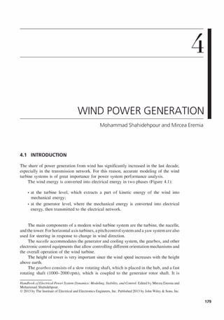
  • 1. 4 WIND POWER GENERATION Mohammad Shahidehpour and Mircea Eremia 4.1 INTRODUCTION The share of power generation from wind has significantly increased in the last decade, especially in the transmission network. For this reason, accurate modeling of the wind turbine systems is of great importance for power system performance analysis. The wind energy is converted into electrical energy in two phases (Figure 4.1): • at the turbine level, which extracts a part of kinetic energy of the wind into mechanical energy; • at the generator level, where the mechanical energy is converted into electrical energy, then transmitted to the electrical network. The main components of a modem wind turbine system are the turbine, the nacelle, and the tower. For horizontal axis turbines, apitchcontrol system and a yaw system are also used for steering in response to change in wind direction. The nacelle accommodates the generator and cooling system, the gearbox, and other electronic control equipments that allow controlling different orientation mechanisms and the overall operation of the wind turbine. The height of tower is very important since the wind speed increases with the height above earth. The gearbox consists of a slow rotating shaft, which is placed in the hub, and a fast rotating shaft (l000-2000rpm), which is coupled to the generator rotor shaft. It is HandbookofElectrical Power System Dynamics: Modeling, Stability, and Control. Edited by Mircea Eremia and Mohammad Shahidehpour. © 2013 by The Institute of Electrical and Electronics Engineers, Inc. Published 2013 by John Wiley & Sons, Inc. 179
  • 2. 180 WIND POWER GENERATION Rotor blades Generator Connection ==:::> ==:::> ==:::> ==:::> ==:::> interface 1--+-+ Flow energy of the air Kinetic Mechanical Mechanical energy energy energy Electrical energy Conversion Transformation Conversion Transformation Electrical network Figure 4.1. Functional chain and conversion stages of a wind energy converter. also equipped with a mechanical disc brake, which is coupled to the generator, and a cooling system for oil. The gearbox introduces, besides a large weight (several of tons), the most maintenance issues. In general, the wind turbines are designed with three blades that better capture the wind energy and allow its transfer to the slower shaft. A pitch control (electromechanical) system acts in certain conditions to change the position of the blades with respect to their longitudinal axis and thus to control the mechanical couple and to limit its power. Also, the blades can achieve an aerodynamic brake by "cut-in speed" (perpendicular to wind direction) or only by turning their extremities. The pitch control can be passive or active, as the blades are bolted onto the hub at fixed angle or the blades can be turned out or into the wind to achieve the highest efficiency. A stall control system is also used to control the power of the wind turbine by changing the aerodynamic design of the rotor blades. At low wind speeds, the stall control acts similarly to the pitch control, whereas at high speeds, the blades are pitched slightly opposite to that achieved by a pitch control. The yaw control system, which uses electric actuators, allows orientation ofthe nacelle facing the wind. An anemometer and a wind vane located on the nacelle roof are used to provide the data necessary for the guidance control system to trigger or stop the wind turbine according to wind speed. Some manufacturers have tried to suppress the gearbox by introducing the "direct attack" system, or to reduce it. This requires a special electrical generator capable of running at the same speedwith turbine rotor speed, whichmeansthatthe generator must be designed with a large number of poles pairs [1]. Figure 4.2 shows the arrangement of the components in the nacelle for two types of wind turbines. Figure 4.2a shows the conventional drivetrain design in the form ofa geared transmission with a high-speed generator. Figure 4.2b, by contrast, shows the gearless variant with the generator being driven directly from the turbine. A wind turbine can be equipped with an induction generator or a synchronous generator. In terms of the rotational speed, in general, wind turbine systems can be classified into two types: fixed speed and variable speed. The largest machines tend to operate at variable speed, whereas smaller and simpler turbines are of fixed speed.
  • 3. SOME CHARACTERISTICS OF WIND POWER GENERATION (a) (b) Figure 4.2. Nacelle of a wind turbine with (a) gearbox and high speed ( Courtesy of General Electric) [2] and (b) a gearless wind turbine ( Courtesy of Enercon). 4.2 SOME CHARACTERISTICS OF WIND POWER GENERATION THE AERODYNAMIC PROFILE OF WIND TURBINE'S BLADES. Figure 4.3 shows the general aspect of a horizontal axis wind turbine as well as the blades aerodynamic profile. Figure 4.3b and c shows the cross section of a rotor blade andthe forces that act on the blade. In terms of the wind direction, the wind turbine rotor is turned round propelled by drag or lift forces. The lift force (L) is perpendicular to the direction of the relative wind velocity (Vrel), while the drag force (D) acts in the direction ofit. The relative wind velocity is composed of the blade motion (VBlade) and the wind velocity (Vw). ............... ..··�:i��··." /;::bine's "'::;;..r--r-..;:: co " ntrol "", i.· . · . · . · . · . rotation 1 J .. .. ... : Plane of relative wind ___ -:!........._ ....... 0 (Drag) Chord lin�-7-- ��--:::..-:�:--..._ ._ Plane and direction----.:�=�""''''''''"- of rotation (c) D � /P (b) Figure 4.3. General view and cross section of a wind turbine blade with relative wind comprising the rotating wind (VBlade) and ambient wind (Vw). 181
  • 4. 182 WIND POWER GENERATION The wind forces acting on a blade section depend also on the angle of incidence cp between the plane of rotation of the rotor blades and the plane of relative wind (Figure 4.3c). The angle of incidence cp is determined by the ambient wind speed Vw and the speed of the blade VBlade(= - WtR). Ifthe tip-speed ratio A is defined as the ratio ofthe rotational speed ofthe tip ofa blade to the actual speed of the wind, that is (4. 1) the angle of incidence can be calculated as cp= atan (:t;)= atan G) where WI is the mechanical angular speed ofthe turbine rotor and R is the wind turbine rotor radius. The modem wind turbines are provided with control possibilities of the pitch angle {3 through a servomechanism. By turning the blade, the angle of attack CI between the chord line ofthe blade and the plane of relative wind (VreD will change accordingly [3]. Older and simpler wind turbines have constant blade angle {3, which is called stall (or passive stall) control. MECHANICAL POWER OF WIND TURBINE. The power ofan air mass that flows perpendic­ ularly on an area A at the speed Vw is given by the expression [3] : 1 3 Pw= 2 pAVW ( W) (4.2) where p is the air density (kg/m3), A= rrR2 is the area swept by the rotor blades (m2), VW is the average windspeedpassing through the A surface (m/s), and R is thewind turbine rotor radius (m). Integrated in time, the total available wind energy is obtained. The power in wind energy is converted into mechanical-rotational energy by means of the wind turbine rotor. However, the wind energy cannot be entirely extracted by the wind turbine. The power extracted from wind by the turbine is determined by multiplying the available wind power Pw with an efficiency coefficient Cp that is, (4.3) where Cp is the performance coefficient, which depends on the aerodynamic properties of the blades, A is the tip-speed ratio, and {3 is the blade pitch angle. According to Betz's law [4], the theoretical maximum power that can be extracted from wind is only 59.3% of the available power, that is, 1 3 PBeiz= CpBelZPW= 0.59 x 2 pAVw (4.4) In practical designs, modem turbines can achieve efficiencies below 40%. The efficiency of the turbine is a function of the wind speed, and therefore efficiency may vary from case to case.
  • 5. SOME CHARACTERISTICS OF WIND POWER GENERATION P(MW) 1.6 1.4 1.2 1 0.8 0.2 5 10 Hysteresis . loop � : Rated wind 15 20 25 v (rnls) Figure 4.4. Power curve of a 1.5MW (d=82m) wind turbine with active pitch control [3,5]. Ifthe rotor of the wind turbine rotates too slowly, the energy captured by the turbine is too low, whereas in case of a very high velocity, the surface formed by the blades will appear as a wall that may be a danger for the wind turbine. Assuming a wind turbine with the blades diameter d= 82 m, the maximum power that can be extracted by the wind turbine at the wind speed Vw= 12 m/s and a performance coefficient Cp= 0.4 is 1 3 1 2 3 PT= CpX2:PAVw= 0.4'2:.1.225'lT.41 ·12 = 2.236 MW POWER CURVE. The power curve relates the power developed by the wind turbine and is represented for wind speed values between the cut-in speed and the cut-out speed (Figure 4.4). At wind speeds lower than the cut-in speed value and higher than the cut-out speed value, the turbine does not operate. The rated capacity is reached at wind speed values between 12 and 16 mis, depending on the individual wind turbine design. The power produced by the wind turbine above the rated wind speed is limited to the rated capacity, and therefore only one part ofthe available wind power is used. This can be achieved by pitch control or by stall control. The power curve is sensitive to the air pressure (which vary with the height above sea), changes in the aerodynamics of the rotor blades (which can be affected by dirt or ice), shadowing or wake effect, and so on. The wind turbine shuts down if the wind speed exceeds the cut-out speed, that is, 20-25 mls. However, the wind speed may drop below then may exceed again the cut-out speed. For this reason there is a delay, referred to as the hysteresis loop (Figure 4.4), after which the wind turbine starts operating again. Usually, the wind turbine restarts ifthere is a drop in wind speed of 3-4 mls below the cut-out speed. For the power system, shutting down a large amount of power generation may create significant problems. To avoid this, the wind turbine is provided with step-by-step power reduction at increased wind speeds instead of sudden cut-out. PERFORMANCE COEFFICIENT. The performance coefficient, denoted by Cp, shows the efficiency of power extraction by the wind turbine from the wind. It varies with the wind speed, the rotational speed of the wind turbine, and turbine blade parameters such as angle of attack and pitch angle. Usually, it is represented as a function Cp(..1., (3) in terms of the tip-speed ratio A and blade pitch angle f3. Figure 4.5 shows the performance coefficient 183
  • 6. 184 Cp (p.u) 5 �)Illax 3 2 0 -0.1 0 A, (p.u) 5 10 15 WIND POWER GENERATION Figure 4.5. Cp(J" (3) characteristics with con ­ trol of the blade pitch angle ( 1). characteristics for various blade pitch angles and tip-speed ratios. It has a peak at a given value of A and drops off to zero at higher tip-speed ratios. The wind turbines are designed/chosen in terms of the average wind speeds. A good wind site may have average wind speeds ranging around 7-10 mis, and therefore the wind turbines should be designed to extract the maximum amount of wind energy possible at wind speeds between 10 and 15 m/s. Higher speeds have a low frequency of occurrence, and therefore using oversized turbines might be economically inefficient. Furthermore, higher speeds add significant stress on the turbine. As shown in Figure 4.4, the wind turbine operates at constant power if the wind speed exceeds the rated wind speed and keeps operating until the cut-out speed is reached. Therefore, the turbine needs to be provided with a control mechanism to regulate the generated power when the wind speed increases above the rated wind speed. This control can be achieved in two ways [3] : • Fixed-speed designs that typically use stall. • Variable-speed designs that typically use dynamic blade pitch control. CAPACITY FACTOR. Directly related to the wind profile at the site where the turbines are located, one way to evaluate the economic efficiency of an individual wind turbine or of a wind power plant is by calculating the capacity factor: C . f Actual annual energy produced apaclty actor = - - --,---- -,--- ..,...,. ...,...----==:..:.....,"---- ---..,.- -::- .,..,.---- ,-­ Annual energy that could be produced at full capacity Investment in wind generation is typically reasonable economic for capacity factors above 0.25, while values above 0.3 are considered of high economic efficiency. On the other hand, offshore sites have higher economic efficiency compared to onshore sites, having capacity factors ranging from 0.35 to 0.45. 4.3 STATE OF THE ART TECHNOLOGIES 4.3.1 Overview of Generator Concepts There are several types of three-phase generators that can be used in wind turbines, as shown in the classification presented below [3].
  • 7. STATE OF THE ART TECHNOLOGIES Induction (asynchronous) generator Squirrel cage induction generator (SCIG) Wound rotor induction generator (WRlG) Dynamic slip­ controlled induction generator (DSIG) Doubly fed induction generator (DFIG) Synchronous generator Permanent magnet synchronous generator (PMSG) Wound rotor synchronous generator (WRSG) The wind turbine generators (WTGs) can also be classified into two categories in terms of the rotational speed, that is, fixed-speed (FWTGs) and variable-speed (VWTGs). Fixed-speed wind turbine generators have simple design and are directly connected to the power grid, whereas the variable-speed wind turbine generators incorporate power electronic-based converters as interface for connection to the power grid. 4.3.1.1 General Description. INDUCTION GENERATOR. The induction generator is the most common type of electrical machine used in wind turbine systems because it is simple, reliable, lightweight, and cheaper. The main disadvantage is that it requires a reactive magnetizing current to produce the rotating magnetic field, which can be established once the generator is connected to the main power grid. Once connected, the generator can be self-excited. It is preferred that the reactive power be provided by an external source, such as a capacitor bank, and not from the main power grid. The amount ofactive power produced by the induction generatoris proportional to the slip, that is, the difference between rotor angular speed and the stator angular speed of the generator. The rotor speed depends on the torque developed by the turbine. When the wind speed is very low, below the cut-in speed, the turbine cannot develop enough torque and the generator behaves as a motor absorbing current from the grid. To avoid this situation, the wind turbine is disconnected from the grid. The rotor of an induction machine may be one of two types: the squirrel cage and the wound rotor. Squirrel Cage Rotor. The rotor of a squirrel cage machine is designed with a series of bars placed in slots near the rotor surface, which are short-circuited by end rings at each end of the rotor (see Figure 2.69b). The SCIG wind turbine is directly connected to the power grid and the influence between active power, reactive power, terminal voltage, androtor speed follows a strict relationship. The generator is supposed to operate at fixed speed since the maximum variation in the rotor speed is around 2%. Furthermore, as the wind turbine produces more active power, the generator absorbs more reactive power from the external source. Because the wind speed varies continuously, the reactive power compensation must be performed dynamically. Cage generators are remarkable for their extremely simple layout that permits robust construction and operational reliability even in the event of rough handling. Wound Rotor. The wound rotor machine consists of a rotor core designed with three­ phase windings instead ofbars, but with the same number ofpoles as the stator. The advantage of using windings instead ofbars is that the wires can be brought out and connected externally through slip rings and brushes or by means of power 185
  • 8. 186 WIND POWER GENERATION electronic converter (which may or may not require slip rings and brushes), so that the current through the windings can be controlled. By using a power electronic converter, the power can be extracted from or injected to the rotor circuit and the induction generatorcan be magnetized from either the stator circuit or the rotor circuit. It is also possible to recover slip energy from the rotor circuit and feed it into the output of the stator. The most common configurations of wound rotor generators are the DSIG and the DFIG [3]. • The dynamic slip-controlled induction generator is a special configuration of a wound rotor induction generator in which a variable external resistance is attached to the rotor winding. This configuration allows the generator to have a variable slip in order to reduce the fluctuations in the torque and power output, especially during gusts. The slip is simply varied by changing the total rotor resistance using a power electronic converter. One type of dynamic slip­ controlled induction generator is the OptiSlip design, a Vestas registered mark, where the external resistor and the switches are mounted on the rotor shaft and the control signal is transmitted via optical fiber. • The doubly fed induction generator is another configuration of a wound rotor induction generator in which the rotor is separately controlled. The stator windings are directly connected to the power grid, and the rotor windings are separately connected to the grid through a bidirectional back-to-back IGBT-based voltage source converter (VSC). Reactive Power Compensation. Either configuration ofan induction generator needs a reactive magnetizing current to build up the magnetic field, although reactive power does not contribute to direct energy conversion. The higher the reactive current content in the overall current, the lower is the power factor. An induction machine is not "excited" like a synchronous machine, and therefore it takes the reactive power from the grid. Figure 4.6a shows the variation of the reactive power absorbed by the induction generator from Reactive power (p.u.) 4 3.5 3 2.5+---_ 2 1.5 1 0.5 �0.2 Generator -0.1 o Motor operation Slip (p.u.) 0.1 0.2 (a) Voltage of POC (p.u.) Gene�ator 1.05 oper�tion 1.0 0.9 0.8 0.7 M<!tor oper�tion XIR=lD Slip 0.6 (p.u.) 0.55 ±--+---+--+--=i- .... -0.1 -0.5 0 0.5 0.1 (b) Figure 4.6. Reactive power drawn by an inductive generator and voltage at the point of connection: (a) reactive power variation with slip; (b) voltage at the point of connection. (Reprinted with permission from Ref. 5.)
  • 9. STATE OF THE ART TECHNOLOGIES the grid, and Figure 4.6b shows the voltage at the point of connection (POC) to the main grid [5]. Two cases are considered in Figure 4.6: a strong network (short-circuit power of 3600 MVA) and a weak network (short-circuit power of 360 MVA) through a transmission line having aX/R ratio of 10. It can be seen that as the slip or the active power generation increases, the amount of reactive power absorbed by the generator also increases. A large amount of reactive power absorbed from the grid results in significant voltage drop on the transmission line. The voltage at the point of connection with the network decreases as the slip increases (Figure 4.6b). SYNCHRONOUS GENERATOR. There are two types of synchronous generators commonly used by manufacturers in the modem wind turbines [3]: • The wound rotor synchronous generator. • The permanent magnet synchronous generator. The synchronous generator does not need a reactive magnetizing current since the magnetic field can be created by permanent magnets or a conventional field winding. Furthermore, if the generator is designed with a greater number of poles, the gearbox can be removed, case in which the generator operates at the same rotational speed as the turbine. In order to achieve a full control, the synchronous machine-based wind turbines are connected to the grid through a power electronic converter. Today, the synchronous generators used for wind turbines lie in the range between a few kW to 7 MW. Conventionally constructed synchronous machines of this size use salient-pole rotors. The rotor comprises the pole shoes, the poles lying beneath, and the exciter windings. The stator consists of the stator core and AC windings. The simplified configuration of a brushless generator is shown in Figure 4.7 [6]. The rotor is supplied by the exciter, which consists of exciter poles in the stator, rotary field windings, and a rectifier bridge at the end ofthe shaft. The exciter or the exciter coils in the stator are supplied from the pilot exciter. Rotating an outer permanent magnet generates current in the pilot exciter coils, which is fed via a voltage controller to the main exciter a b c N Rotary field winding Main AC generator 8f-------l f @? Rectifier E " I :' permanent : bridge .....�:.I���.C.�I.�. .)...�a.����...: AC Exciter Pilot exciter Figure 4.7. Synchronous generator structure of a self-regulating brushless model ( Courtesy of AvK). 187
  • 10. 188 WIND POWER GENERATION coils. In this way, the necessary magnetic field is set up in the poles of the exciter and crosses the air gap to the AC windings of the exciter [6]. This type of construction is preferred for grid-independent power supplies. If a grid is available to power the exciter windings, the pilot exciter becomes superfluous. In brushless machines, the exciter current is fed from the stator windings, across the air gap of the exciter, and via the rotating rectifier bridge to the rotor. Its rotating magnetic field-rotary field-is transferred to the stator. The much simpler construction ofthe machine and the gain in dynamic characteristics must, however, be set against the severe disadvantage offeeding electricity through brushes and slip rings. Higher frictional losses, brush and slip-ring erosion, and higher maintenance costs are the consequences. 4.3.1.2 Squirrel Cage Induction Generator. The simplest electrical topology of a wind turbine system incorporates a fixed-speed wind turbine with a squirrel cage induction generator. The basic configuration of the wind turbine system is shown in Figure 4.8 [7] . The main components of a SCIG wind turbine system are turbine aerodynamics, blade control system, mechanical drive train, induction generator, reactive power compensation device, coupling transformer, protection (especially under voltage protection). This type of wind turbine is directly connected to the electrical network. For this reason it is simple and cheap. Furthermore, no synchronization device is required. However, the wind turbine has to operate at constant speed as the frequency of the grid determines the speed of the generator rotor. This requires a special mechanical structure capable to absorb the high mechanical stress caused by wind gusts. Another disadvantage of the induction generators is the high starting current due to sudden magnetization in the instant of coupling to the network and the need for reactive power. Connection of the induction generator to the grid generates an in-rush current, which can be up to five to eight times the rated current, causing severe voltage disturbance on the power system. This current is limited by use of a soft-starter, which consists of two thyristors, connected antiparallel, as commutation devices in each phase. Connection ofthe generator to the electrical network is assisted by adjusting the firing angle of the thyristors in a predefined number of grid periods. Once the wind turbine is cut-in, the thyristors are short-circuited by switches. The reactive power required by the generator for maintaining the magnetization is provided by capacitor banks. The main characteristics of a SCIG wind turbine are shown in Table 4. 1 [7]. Rotor blades Squirrel cage rotor induction generator Soft-starter Capacitor bank Electrical network Figure 4.8. The basic configuration of a S CiG wind turbine (7).
  • 11. STATE OF THE ART TECHNOLOGIES TAB L E 4.1. Main advantages and disadvantages of SCIG Advantages • Robust standard generator • Relatively low cost • No power electronics Disadvantages • The power produced is not optimized • Requires maintenance of gearbox • It cannot control the reactive power • The magnetization of the generator is made from the network 4.3.1.3 Dynamic Slip-Controlled Wound Rotor Induction Generator. In order to improve the torque-slip controllability of the induction generator, a variable resistor Rc is introduced in series with the rotor circuit (Figure 4.9) [7]. The external resistor is connected to the rotor windings through a power electronic converter, and the currents flow between the resistor and the rotor via slip rings. This solution is known as dynamic slip control and ensures a speed variation in the range of 1-10%. The power converter is designed for low voltage and high currents. Alternatively, the resistors and electronics can be mounted on the rotor, eliminating the slip rings (the Weir design). Use of power electronic allows the rapid control of the rotor currents so that the output power can be kept constant even during gusting conditions, and can help the machine to perform better during grid perturbations. When operating below rated wind speed and power, the WRIG wind turbine acts similar to a fixed-speed wind turbine. However, above rated values, by controlling the resistance it is possible to control the air-gap torque and thus the slip. Besides the sensitive growth of the energy that can be captured from the wind, a reduction of the influence of wind gusts on the active power produced by the generator is obtained. The speed range is typically at most 10% as it depends upon the size of the resistance and the slip power is dissipated in the resistor [3,7]. The main characteristics ofinduction generator with control of the rotational speed by an external rotor resistance are presented in Table 4.2 [7]. This solution preserves the same drawbacks as the previous squirrel cage induction generator. Rotor blades Wound rotor induction generator Soft-starter Capacitor bank Electrical network Figure 4.9. Basic configuration of a variable-speed wind turbine with external rotor resistor. 189
  • 12. 190 WIND POWER GENERATION TAB L E 4.2. Main advantages and disadvantages of WRIG Advantages Disadvantages • Variable speed (0 to + 1 O%Wsynchronism) • Robust design • Low power converter with power electronics • The power produced is not optimized • Requires maintenance of gearbox • It cannot control the reactive power • The magnetization of the generator is made from the network 4.3.1.4 Doubly Fed Induction Generator. A large number of modem wind turbines are equipped with a DFIG that has the stator connected directly to the electrical network, meaning that it operates synchronously at the network frequency, and the three­ phase wound rotor connected via a back-to-back voltage source converter and a trans­ former, as shown in Figure 4. 10 [7]. The main advantage ofthe DFIG wind turbines is their ability to supply active power at a constant voltage and frequency while the rotor speed may be varied. As the magnetization of the DFIG can also be provided from the rotor circuit, the reactive power can be controlled independently ofthe active power. The rotor circuit can provide reactive power to the stator via the grid-side converter. The back-to-back converter allows the control ofthe electromechanical torque and the rotor excitation. The size of the converter is a fraction of the generator rating, normally in the range between 15% and 30%. Since the power converter operates in a bidirectional way, the DFIG can be operated either in subsynchronous or in supersynchronous operational mode, with a variation of ±30% with respect to the synchronous speed. On the other hand, the DFIG wind turbine may cause some problems during a grid fault when its rotor circuit, together with the back-to-back converter, is exposed to a high overcurrent induced by a high transient stator current. In this case, the wind turbine should be disconnected from the network in order to avoid some damage to the electrical or mechanical part. However, this solution is not acceptable in the case of short-term grid disturbances due to passive grid stability problems and thus some active protection systems need to be applied to keep the turbine connected to the network but also protected against any overcurrent. Electrical network Rotor blades Wound rotor Rotor-side converter converter Power converter Figure 4.10. Basic configuration of a doubly fed induction generator. Variable speed drive [7].
  • 13. STATE OF THE ART TECHNOLOGIES (' (a) (b) (c) Figure 4.11. Crowbar arrangement [8,9). TAB L E 4.3. Main advantages and disadvantages of DFIG Advantages Disadvantages • Possible speed regulation for optimal utilization of energy (±30% Wsynch) • The power electronics is designed at 30% Pn • Reactive power for magnetization of the machine is provided by the power converter • Standard asynchronous machine • Grid connection easy to administrate • Requires maintenance of gearbox • The cost of the power electronic equipments • Control-command complex systems of the entire unit • Slip rings and brushes wear and tear, maintenance One solution is to connect a crowbar (Figure 4.10) to the rotor terminals, designed to bypass the rotor-side converter, that is, to short circuit the rotor, in order to avoid overcurrent on the rotor-side converter as well as overvoltage on the DC-link capacitor. Figure 4. 1 1a shows the architecture ofa crowbar consisting of antiparallel connected thyristors with external resistors. The crowbar can also be constructed by using diode bridge and a single thyristor, as shown in Figure 4. 1 1b [8]. The crowbar is connected in case of either a DC-link overvoltage or a rotor-side converter overcurrent. Because of technical limitations of the two arrangements, the rotor current is not interrupted immediately. Furthermore, the crowbar remains connected until the stator is disconnected from the power grid. This is not acceptable under the present grid codes requirements. In order to remove the crowbar fast enough, an active crowbar is used, in which the thyristor is replaced with a GTO-thyristor or an IGBT (Figure 4. 1 1c). The main advantages and disadvantages of the doubly fed induction generator are presented in Table 4.3 [7,10]. 4.3.1.5 Wound Rotor Synchronous Generator. The stator windings of a wound rotor synchronous generator are connected to the electrical network through a bidirectional power converter consisting oftwo back-to-back connected pulse width modulation (PWM) voltage source converters. The generator-side converter regulates the electromagnetic torque, whereas the network-side converter regulates the active and reactive powers produced. The DC excitation current supplied to the rotor winding is provided by a rotating rectifier through slip rings and brushes; brushless exciter is also used. Therefore, no external source of reactive power is required. The frequency (in Hz) of the currents 191
  • 14. 192 WIND POWER GENERATION produced by the stator is determined by the mechanical speed (in rpm) of the rotor and the number of pole pairs. The main advantages of the wound rotor synchronous generator are as follows: • The efficiency of the machine is usually high since the whole stator current is used for the electromagnetic torque production. • The WRSG with salient poles allows the direct control of the power factor, minimizing the reactive component of the stator current in any operating circumstances. • Is it possible to design the generator with smaller pole pitch and therefore multiple pole pairs. This could be a very important characteristic in order to obtain low-speed multiplier machine, eliminating the gearbox. However, the existence of a winding circuit in the rotor may be a drawback as compared to permanent magnet synchronous generator. In addition, in order to allow the generator to regulate both the active and reactive powers, the frequency converter is typically sized 1.2 times the rated active power. Some variable-speed wind turbine manufacturers, for example Enercon and Lagerwey, use a low-speed multipole WRSG. The advantage is that the gearbox is removed, but the price is a large and heavy generator and a full-scale frequency converter sized to handle the full power of the wind turbine system. Another solution is the four-pole (high speed) WRSG used by Made, which requires a gearbox. 4.3.1.6 Permanent Magnet Synchronous Generator. The excitation of a permanent magnet synchronous generator is provided by the permanent magnets, and therefore no rotor winding is needed. Compared to the generators with excitation winding on the rotor, the PM machine has the advantage oflower rotor losses, smaller dimensions of the rotor, simpler cooling circuit (the rotor does not require cooling), and reduced failures. However, the costs for manufacturing the permanent magnets are very high, and an appropriate cooling system is required since the permanent magnets are sensitive to high temperatures. The permanent magnet generator requires the use of a full-scale power converter for connection to the power grid in order to adjust the voltage and frequency at the generator terminal to those ofthe power system. Furthermore, during external short circuits and wind gusts the permanent magnet machine may cause very stiff performance. Although the converter is an added cost, it allows the generator to operate at any speed so as to fit the current conditions [3]. The rotor is provided with permanent magnet poles and, in terms of the rotational speed, it may have salient poles or may be round. Salient poles are more usual in low-speed machines and may be more suitable for wind turbines. The most common types of PM machines are the radial flux machines, the axial flux machines (Figure 4. 12), and the transverse flux machines [6]. The synchronous nature of the PMSG may cause problems during start-up, synchro­ nization, and voltage regulation. It does not readily provide a constant voltage [3]. ARCHITECTURE OF PERMANENT MAGNET GENERATOR-BASED WIND TURBINE. Figure 4. 13 shows the arrangement of a permanent magnet generator connected to the power grid through a frequency converter, consisting of a three-phase diode rectifier (passive), a PWM
  • 15. STATE OF THE ART TECHNOLOGIES (a) Stator pack with winding and iron core Rotor with (b) Figure 4.12. Schematic representation of double air gap designs for machines with (a) axial; (b) radial air gap. (Reproduced from Ref. 6.) Generator-side Network-side DC booster Figure 4.13. Permanent magnet synchronous generator with a boost chopper (5). voltage source inverter, and a DC booster. The DC booster is used to regulate the DC-link voltage, whereas the network-side converter controls the operation of the generator. The reference power to the network-side converter is optimized according to the maximum power-speed characteristic shown in Figure 4.33. This configuration can include or not a gearbox. The disadvantage of this arrangement is that the diode rectifier increases the level of harmonic distortion and the current amplitude of the PMSG. For this reason, this configuration has been considered for small-sized wind turbine systems ($50 kW). This issue was overcome using a PWM rectifier instead of the diode rectifier, shown in Figure 4. 14. Generator-side turbine Network-side converter Electrical network Figure 4.14. Permanent magnet synchronous generator with PW M converter (5). 193
  • 16. 194 WIND POWER GENERATION (b) Figure 4.15. Drive trains of (a) conventional wind turbine; (b) direct-drive generator. The controllable IGBTs allow the generator-side converter to control the generator operation, whereas the network-side converter controls the DC-link voltage and therefore the active and reactive powers exported to the network. FROM HIGH-SPEED TO LOW-SPEED GENERATORS. Large wind turbines were classically designed with generators with small number of poles and high speeds, up to 1500rpm at 50 Hz and 1800 rpm at 60 Hz. As the turbine speed is much lower than the generator speed, typically between 20 and 60 rpm, a gearbox was required between the turbine and generator to adapt the speed. In order to eliminate the problems introduced by the gearbox (e.g., high losses and high noise), nowadays there is a trend to use low-speed generators, which can be directly connected to the turbine shaft. Figure 4. 15 shows comparatively the drive trains of a conventional wind turbine and one with a direct-drive generator [11]. Direct connection ofthe generator to the turbine involves a very high torque developed at the rotor shaft. For instance, a 500 kW direct-drive generator, with 30 rpm, has the same rated torque as a 50 MW steam turbine generator, but with 3000 rpm [5]. It is important to know that the size and the losses ofa low-speed generator depend on the rated torque rather than on the rated power. High-rated torque direct-drive generators are usually heavier and less efficient than the conventional ones. In order to increase the efficiency and reduce the weight of the active parts of the wind turbine, these generators are usually designed with large diameter of the rotor and small pole pitch (which means a large number of poles). PERMANENTMAGNETVERSUSWOUNDROTOR. A synchronous generator is self-excited from the rotor excitation, consisting of either permanent magnets or current-carrying winding. The excitation current of a wound rotor synchronous generator is adjustable and, conse­ quently,theoutputvoltage canbe controlledindependently oftheloadcurrent [5]. Thisiswhyin the classical power plants, where the generators are connected directly to the power grid, the rotors are provided with woundrotorsratherthan permanent magnets. The generators ofmodem wind turbines are connected to the grid through a flexible power electronic-based interface; therefore, the advantageofcontrollable no-loadvoltage is ofless importance. Instead, compared to the permanent magnet rotor, the wound rotor is heavier and has higher losses. Permanent magnet excitation avoids the field current supply or reactive power compensation facilities needed by wound rotor synchronous generators and induction generator and it also removes the need for slip rings [12]. The main advantages and disadvantages of the permanent magnet synchronous generator configuration are presented in Table 4.4 [7]. As the diameter of the turbine rotor increases, the permanent magnet generators seem to be the first choice for the wind turbines manufacturers.
  • 17. STATE OF THE ART TECHNOLOGIES TAB L E 4.4. Main advantages and disadvantages of PMSG Advantages • Variable-speed operation (0-1 00% of the nominal speed) • Optimization of extracted wind power when the wind speed is low • The gearbox can be removed • Very low rotor losses • Simple rotor with no parts likely to wear and tear Disadvantages • High diameter of the machine • The cost of the power electronic equipments (dimensioned at 1 00% Pn) and of the machine (which is not standard) • Power losses in power converter • High costs of permanent magnets • Possibility of demagnetization • Insufficient experience in construction and installation 4.3.2 Overview of Wind Turbines Concepts 4.3.2.1 Fixed-Speed Wind Turbines. The early large-sized wind turbine tech­ nologies were based on generators operating at fixed speed, that is, the rotor speed is constant regardless of the wind speed, and is determined by the power grid frequency, the generator characteristics, and the gear ratio. The induction generator (squirrel cage or wound rotor) is more suited to operate at fixed speeds and its stator can be connected directly to the power grid through a soft-starter (see Figure 4.8). In case of a squirrel cage generator, the slip and hence the rotor speed can be varied, but the variation is very small so that the wind turbine is referred to as a fixed-speed system. Induction generators operate at higher speeds, and therefore a gearbox is used to transfer the mechanical energy from the low-speed shaft of the aerodynamic rotor to the high-speed shaft driving the generator. For size and cost reasons, the induction generator operates at a standard nominal speed of 1500 rpm. In terms of the rated power, the gearbox must provide a gear ratio of about 30-100. A solution to increase the power production was to design a squirrel cage induction generatorrunning at two different, but constant, speeds. This is possible by changing the number of stator pole pairs from eight poles for low wind speeds to four to six poles for high wind speeds. 4.3.2.2 Variable-Speed Wind Turbines. As the technology became more mature and advancements have been done especially regarding the generator and power electronic­ based interface with the electrical network, the wind turbines have been designed with variable speeds. The aim has been to capture as much as possible energy from the wind. Thus, the variable-speed wind turbines are designed to maximize the aerodynamic efficiency over a wide range of wind speeds. The two variable-speed wind turbine topologies are the partial-scale converter wind turbine based on doubly fed induction generator (Figure 4.16) and the full-scale converter wind turbine (FCWT) based on synchronous or induction generator (Figure 4.17) [l3]. Variable-speed operation of the wind turbine allows continuous change-increase or decrease-of the rotational speed, in terms ofthe wind speed Vw, so that the tip-speed ratio A can be maintained constant at the optimal value, which corresponds to the maximum power coefficient. Contrary to a fixed-speed system, a variable-speed system maintains the generator torque fairly constant and the variations in wind are absorbed by changes in the generator rotor speed. To allow the wind turbine to operate at variable speed, the mechanical rotor speed and the electrical frequency of the grid must be decoupled. 195
  • 18. 196 Partial-scale frequency converter r-----l'" WIND POWER GENERATION Electrical network Figure 4.16. Partial variable-speed wind turbine system using doubly fed induction generator with wound rotor [5,1 3]. This means that the electrical frequency of the generator may vary as the wind speed changes, while the grid frequency remains unchanged [5]. For this reason, the variable­ speed wind turbines are typically connected to the grid through a power converter, which controls the generator operation. The rotor of a doubly fed induction generator (Figure 4.16) is connected to the electrical network through a partial-scale frequency converter, sized forjust a fraction of the wind turbine rated power. In this way, the mechanical and electrical rotor frequencies are decoupled, and the electrical stator and the rotor frequencies can be matched independently of the mechanical rotor speed. A typical configuration of afull-scale frequency converter wind turbine is shown in Figure 4.17. The generator is connected to the power grid through a back-to-back converter sized for the full rated power ofthe turbine, decoupling the generator frequency by the grid frequency. In this type of wind turbine, a wide range of electrical machine types may be employed: induction generator, wound field or permanent magnet synchronous generator. Depending on the type of generator used, the wind turbine may include or not a gearbox. In the direct-drive (gearless) configuration, the turbine and the generator rotors are mounted on the same shaft, which means that the generator is designed with large-diameter WRSG Full-scale frequency converter (a) PMSGI Full-scale Electrical WRIG frequency converter network (b) Figure 4.17. Full variable-speed wind turbine systems: (a) wound rotor synchronous generator; (b) wound rotor induction generator or permanent magnet synchronous generator [5, 1 3].
  • 19. STATE OF THE ART TECHNOLOGIES and multiple poles, capable to run at low speeds. On the other hand, a smaller generator with a smaller number of poles requires a gearbox [14]. As the grid codes have become more restrictive regarding the immunity of the wind turbines to grid faults, variable speed and full-rated electronic interface are currently the only choice of the manufacturers for large wind turbines. Compared to other alternatives, the full-scale wind turbine offers several advantages, such as [8] • decoupling between the grid and the generator minimizes the effects of a grid fault from propagating to the generator, and therefore provides better fault response; • the full-size generator-side converter facilitates a large operating speed range for the turbine, which improves the wind turbine power performance; • the full-size grid-side converter gives more space for the wind turbine to provide reactive power into the grid, particularly during a grid fault. The full-scale wind turbine concept poses, however, some disadvantages: • Higher converter losses, than in a DFIG wind turbine, since the entire output power passes the converter. • The high investment cost of the full converter, although this cost trend is decreasing. In addition to these main wind turbine systems, there are some other configurations to be mentioned. The semivariable-speed turbine is typically equipped with an induction generator of which total rotor resistance can be changed by addition of an external resistor controlled with power electronics (Figure 4.9). Any change in the rotor resistance results in shifting the torque/speed characteristic of the generator. In this way, the rotor speed can be varied (decreased) by about 10% of the rotor speed. Therefore, a semivariable capability is achieved at relatively low cost. The main advantage of variable-speed wind turbines is that more energy can be generatedfor a certain wind speed regime. Although the electrical efficiency decreases due to the losses in the power electronic converters that are essential for variable-speed operation, the aerodynamic efficiency increases. The aerodynamic efficiency gain can exceed the electrical efficiency loss, resulting in a higher overall efficiency. In addition, the mechanical stress is less because the rotor acts as a flywheel (storing energy temporally as a buffer), thus reducing the drive-train torque variations. The main drawback of variable-speed generating systems is that they are more expensive. However, using a variable-speed generating system can also give major savings in other subsystems of the turbine such as lighter foundations in offshore applications, limiting the overall cost increase [13]. 4.3.3 Overview of Power Control Concepts The wind turbine systems are sometimes subjected to high wind speeds causing high aerodynamic forces that act on the turbine blades and also that lead to increased rotor speed. In order to avoid any damages, the wind turbine is provided with various systems to control aerodynamic forces on the turbine rotor [3]. On the generator side, the command system can be split into two essentials functional levels (Figure 4. 18): 197
  • 20. 198 Rotor blades WIND POWER GENERATION Network interface l----H Electrical network Management of operation modes / set point / limitation / protections Figure 4.18. General control structure of a wind turbine [7]. • regulating systems, monitoring systems, and associated protections; • management system of operation modes and protections management. More general can be considered athird level corresponding to the overall management in a wind power plant designed in accordance with the grid codes requirements. The control ofthe power supplied to the main electrical network can be done at each ofthe two levels of conversion and in different ways according to operating conditions: At the turbine level, especially for limiting the power generated during high wind speeds. At the generator level, particularly for variable-speed wind turbine systems, where the energy captured is optimized at low or medium wind speeds. This requires the control of parameters that affect the generator operation (current, speed) or restrictions of the operating system (DC-link voltage, currents through the interface with the electrical network). Limiting the mechanical power developed by the turbine so that the rated power is not exceeded is an essential aspect for a wind turbine. This can be done using different alternatives such as a pitch control, a passive stall control or an active stall control. The last two alternatives are commonly used in a fixed-speed wind turbine, while the first alternative, the pitch control, is used in variable-speed wind turbine. The three control systems of the aerodynamic forces are [3] (i) The stall control (passive control), is the simplest, most robust and cheapest control method, where the blades are bolted onto the hub at a fixed angle. The aerodynamic profile of the rotor blades causes the rotor to stall (loss the power surplus) when the wind speed exceeds a certain level [15]. The geometry of the blades limits the lift forces when the wind speed becomes too high and causes a progressive aerodynamic discharge of the blades that will reduce the power captured. This concept has the advantage of not requiring any mechanical or electrical auxiliary system. The disadvantage is that the power captured by the wind turbine is a function only of the wind speed and the rotation speed; there is
  • 21. STATE OF THE ART TECHNOLOGIES P (kW) 700 600 500 400 300 200 100 5 : v (rnls) 10 15 20 25 (a) P (kW) 700 600 500 400 300 200 100 o 5 : v (rnls) 10 15 20 25 (b) Figure 4.19. Typical power characteristics: (a) stall control; (b) pitch angle control [1 6]. no any possibility to adjust the pitch angle. The stall control causes less power fluctuations than a fast-pitch power regulation. However, this method is less efficient at low wind speeds, it has no assisted start-up, and the wind turbine system experiences variations in the maximum steady-state power due to variations in air density and grid frequencies. In case of a stall control wind turbine system, in the event of a fault in the electrical grid, ifthe energy captured by the wind turbine cannot be transmitted to the grid, there must be a mechanical brake on the turbine shaft (high braking torque), dimensioned "to tire" the kinetic energy of the turbine. The brake can be fitted behind the gearbox where the torque is lower, and it is used only as a "parking" brake. An emergency stop can also be provided by the generator under the condition that this one has a resistive electrical circuit for energy recovery, which connects, in case of emergency, to the rheostatic brake. The variation curve of available wind power Pw in terms of the wind speed is shown in Figure 4. 19a [16]. (ii) Thepitch control (active control) assumes that the blades can be turned out of the wind direction as the wind speed becomes too high or turned into the wind when the wind speed decreases below the rated value. This type of control provides a good power control and can contribute at start-up and during emergency stop. Compared to the stall control, where the output power decreases as the wind speed increases above the rated value, the pitch control ensures a constant output power, close to the rated power, for wind speeds above the rated value (Figure 4.19b). The blades are rotated by using electrical or hydraulic devices and allow the pitch angle fJ to be varied between 0° and 25° (up to 30°) [16]. Turning the blades out of the wind, the aerodynamic forces acting on the blades can be reduced to acceptable limits. Because the axial pressing force is reduced, the efforts in the tower are also reduced. This advantage is amplified on variable speed because the extra energy during the gusts of wind, on which the variations are too brutal for blade orientation mechanism to compensate the effects, can be stored by the rotor inertia through its speed variation (if the generator can accept this energy), while the transmitted power remains constant. Mechanical brake is then a parking 199
  • 22. 200 WIND POWER GENERATION Figure 4.20. Pitch control for active stall wind turbine [8). brake. When the wind speed drops below the cut-in speed, the power can be cancelled by turning the blades at f3 = 90° [16]. The mechanism used to rotate the blades involves higher costs and mainte­ nance. Because of the limited speed of the mechanism, the output electrical power exhibits more fluctuations than in the case of the stall control. (iii) The active stall control, referred also to as "assisted stall" or "combi stall," is a combination of the stall control and pitch control. At low wind speeds, the blades arepitchedsimilarto a pitch-controlled wind turbine inorderto achievemaximum efficiency [3]. At high wind speeds, the blades are pitched toward stall, that is, in opposite direction than that employed by an active pitch control system. For this reason, the active stall control is sometimes called negative pitch control. Compared to the pitch control system, aerodynamic braking requires pitch angles of only about -20°, so the travel of the pitch mechanism is very much reduced. Furthermore, in order to keep the output power constant at the rated value only small change of the blade pitch is required [18]. The active stall wind turbine achieves limited power fluctuations and also is able to compensate the variations in air density. Other advantage is that it can assist the wind turbine system in case of emergency stops and during start-up. An example of active stall controller block is depicted in Figure 4.20 [8]. The measured output power is compared to the reference value, which is equal either to the optimum power or to the rated power. The resulted error is passed through a PI controller to provide the required pitch angle value f3'. Because of the physical limitations, the real value must be limited by a pitch rate limiter, which provides the value f3/1. This value is then fed into a pitch actuator. The pitch actuator can be modeled as a first-order time lag system in order to model the hydraulic system of the actuator. In order to avoid unnecessary continuous changes in pitch angle, which may wear the pitch mechanism, the mechanism is allowed to pitch the blades only at specified period of sample times and only if the difference between the new and the old set point exceeds a certain minimum value. For power system stability studies, however, this mechanism can be excluded from the model. 4.4 MODELING THE WIND TURBINE GENERATORS 4.4.1 Model of a Constant-Speed Wind Turbine Figure 4.21 shows the simplified structure of a constant-speed wind turbine model. The most important parts ofthis wind turbine to be modeled are the turbine rotor, the drive train, and the generator. The input to the wind turbine model is the wind speed value Vw, and the link with the electrical network model is given by the active and reactive powers produced, P and Q, and by the actual voltage and frequency, U andf, ofthe networktaken as reference for the wind turbine model.
  • 23. MODELING THE WIND TURBINE GENERATORS Figure 4.21. Simplified structure of a constant-speed wind turbine model [3, 1 9]. WIND SPEED MODEL. One way to model the wind speed is to use historical data of the wind speed measured at the site where the wind power plant is/will be located. The wind speed may vary very much and may have very different characteristics from one moment to another. Therefore, simulations based only on "real" values are limited to those historical data available [20]. Simulation for a complete range of characteristics of the wind, such as wind gusts or turbulence, may require additional measured data. On the other hand, analytical expressions can be established to model the wind based on characteristics chosen by the user, which may also include measured data. A general expression of the actual wind speed, which provides reasonable flexibility in power systems simulations, is made up by the sum of the following components [3,21] : (4.5) where Vw(t) is the wind speed at time t, Vwa (t) is the average value of the wind speed, Vwr (t) is the ramp component, Vwg (t) is the gust component, and VwI (t) is the turbulence component. The wind speed components are all in meter/second, and the time t is in seconds. WIND TURBINE ROTOR MODEL. For electrical simulation, the wind turbine can be represented by the well-known algebraic equation (4.3) of the power extracted from the wind, which gives the relationship between the total available wind power and the performance coefficient. In off-line simulations, both the air density p and the area swept by the turbine blades are considered constant. The wind speed value is obtained from the wind speed model, and the performance coefficient is a controlledterm since it is a function of the pitch angle fJ and the tip-speed ratio A. REPRESENTATION OF THE WIND TURBINE DRIVE TRAIN. A wind turbine drive train can be represented by a multimass system modeled by inertia, angular positions, and angular velocities. The masses are coupled between them through spring constants and damping coefficients. The three-mass model of the constant-speed wind turbine drive train is shown in Figure 4.22. It consists of the following three inertias [8] : • The inertia lb, representing the flexible parts of the blades, which can be flexibly rotated by pitch control. • The inertia lh, representing the rigid parts of the blades bolted into the hub, the turbine hub, the low-speed shaft, and rotating parts of the gearbox that are stiffly connected to the low-speed shaft. • The inertia 19, representing the generator rotor, the high-speed shaft including also a disk brake, and the rotating parts ofthe gearbox that are stiffly connected to the high­ speed shaft. 201
  • 24. 202 WIND POWER GENERATION J" (H,) J" (H,) Jg (Hgl Flexible blades Rigid blades + hub Generator rotor Figure 4.22. The three-mass model of drive train ( Adapted from [8)). In Figure 4.22, eb, eh, and eg represent angular positions of the blades, hub, and generator, Wb, Wh, and Wg correspond to the angular velocities of the blades, hub, and generator, and Hb, Hh, and Hg are the inertia constants of the blades, hub, and generator, respectively. The springs of blades and the low-speed shaft are considered flexible. The elasticity between adjacent masses is expressed by the spring constants: Kbh is the effective blade stiffness and Khg represents the shaft stiffness, resultant of both the low- and high-speed shafts. The damping between masses is represented by damping coefficients: Dbh is the damping coefficient between the blades and the hub, and Dhg is the damping coefficient between the hub and the generator rotor [5,22]. The equations of motion of the three-mass model, expressed in per unit, can be written as [8,22] dWb 2Hb- = Ct - Kbh(eb - eh) -Dbh(Wb - Wh) dt 2HhdWh = Kbh(eb - eh) - Khg(eh - eg) -Dbh(Wb - Wh) -Dhg(Wh - wg) dt 2HgdWg = -Ce + Khg(eh - eg) - Dhg(Wh - wg) dt deg - = Wg dt (4.6) In equations (4.6), Ct is the aerodynamic torque determined as a function of the power extracted from wind by the turbine PTand the blade speed Wb,that is, Ct = PT/Wb,whereas Ce stands for the electromagnetic torque of the generator. The terms corresponding to the damping coefficients of the blades Db, the hub Dh, and the generator Dg have been neglected. The three-mass model involves very large computation time in power system dynamic simulations. For this reason, a simpler model, with two masses, is preferred. In the two-mass model, the drive train of a wind turbine is modeled as two inertias it and ig that are connected to each other through a spring (Figure 4.23). The spring represents the low stiffness of the drive-train shaft. The first mass accounts for the blades, the hub, and the low-speed shaft, whereas the second mass accounts for the high-speed shaft, the gearbox, and the generator rotor. It is supposed that the gearbox is one of main sources of shaft flexibility [8,22,23].
  • 25. MODELING THE WIND TURBINE GENERATORS ' . J, {H,) Wind turbine rotor ' , . �� �-----''----- 19 {Hg) Generator rotor Figure 4.23. Two-mass model of a drive train ( Adapted from [8)). The equations of motion of the two-mass model, expressed in per unit, can be written as [8] 2HtdWI = Ct - Ks(8t - 8g) - Dtg(Wt - Wg) dt 2Hgd :rg = -Ce + Ks(8t - 8g) + Dtg(Wt - Wg) d8g - = Wg dt (4.7) where Ht and Hg are the wind turbine and the generator rotor inertia constant, respectively; Wt and Wg are the turbine and the generator rotor angular velocities, respectively, in revolutions per minute; 81 and 8g are the turbine and the generator rotor angular positions, respectively, in mechanical degrees; DIg is the mutual damping, caused by differences in speeds of the rotor and the turbine shaft; and Ks is the shaft stiffness. In this model, the terms corresponding to the turbine self-damping Dt representing the aerodynamic resistance in the turbine blades, and the generator self-damping Dg representing the damping due to mechanical friction and windage, have been neglected. The drive-train model can be simplified under the form of a one-mass model by removing shaft stiffness and mutual damping between masses. The equivalent inertia is the sum of the generator rotor and the turbine inertias. Therefore, assuming that the turbine angular velocity and the generator rotor angular velocity are equal, the equation of motion of one-mass drive-train model reduces to (4.8) SQUlRREL CAGE INDUCTION GENERATOR MODEL. In order to write the stator and rotor voltage equations of an induction generator in the d-q reference frame, we make use of equations (2.219) and (2.220) of the induction motor, but assuming the generator convention, that is, the current leaving the machine is positive and the current entering 203
  • 26. 204 the machine is negative. Thus, the voltage equations are [24] R . ,I, do/ds Uds = - slds - WS'f'qs + dt · do/qs uqs = -Rslqs + WSo/ds + dt · do/dr Udr = -Rrldr - SWs0/qr + dt · do/qr Uqr = -Rrlqr + SWs0/dr + dt WIND POWER GENERATION (4.9) The subscripts d and q stand for direct and quadrature axis component, respectively, and the subscripts r and s for rotor and stator, respectively. The slip s is defined as pWm s = 1 - -- 2 Ws where p is the number of poles and Wm is the rotor mechanical angular velocity. (4. 10) The impedances are expressed in per unit in order to make them independent of the voltage level and generator rating. Using again the generator convention, the stator and rotor flux linkages from equation (4.9) can be calculated as o/ds = -Lssids - Lmidr o/qs = -Lssiqs -Lmiqr o/dr = -Lrridr -�nids (4. 1 1) where Ws and Wr are stator and rotor electrical angular velocities, in rad/s; Lss and Ler are stator and rotor inductances; and �n is the mutual inductance between stator and rotor. Substituting equation (4. 1 1) in equation (4.9), and neglecting the stator transients, the voltage-current relationships become Uds = -Rsids + ws(Lssiqs + Lmiqr) uqs = -Rsiqs - ws(Lssids + Lmidr) (4. 12) The rotor voltages of a squirrel cage induction generator are equal to zero because the squirrel cage is short-circuited at the ends. The electrical torque Ce is given by (4. 13)
  • 27. MODELING THE WIND TURBINE GENERATORS and the equation of the motion of the generator is (4. 14) The active power generated P and the reactive power consumed Q are (4. 15) The generator exchanges active and reactive powers with the grid only through the stator terminals. Because the rotor is not connected to the grid it does not need to be taken into account [3]. 4.4.2 Modeling the Doubly Fed Induction Generator Wind Turbine System 4.4.2.1 DFIG Model. A doubly fed induction generator is a special design of an induction machine, in which both the stator and the rotor are connected to the power grid. The stator, consisting of three-phase windings with two up to eight poles, is connected to the grid through a transformer. The rotor is also designed with three-phase windings, which are connected to an external stationary circuit via slip rings and brushes. This arrangement allows the rotor exchange power in both directions with the power grid. The general control block diagram of the DFIG wind turbine is illustrated in Figure 4.24 [8,25,26]. The main parts of the DFIG model are the models of the turbine rotor, the drive train, the generator, the rotor-side converter, the grid-side converter with the DC-link, as well as the interface and power grid models. Additional models represent different controls such as -ref 'dr Active power Generator model 'ref iqr '",. r::- --I - -, Reactive power controller Stator curents Stator voltages Reactive ower set point Active power set-point 1 Figure 4.24. Control bloc k diagram of a D F IG wind turbine ( Adapted from (8)). 205
  • 28. 206 WIND POWER GENERATION pitch angle controller, power/speed controller, reactive power controller, and a wind speed model. Similar to variable-speed drive applications (induction motors), the control of the doubly fed induction machine is performed by decoupling the internal controls. The rotating d-q frame is aligned with any synchronously rotating variable, such as the stator flux. In this way a decoupled control between the electrical torque and the rotor excitation current is obtained. In contrast with the squirrel cage induction machine, the excitation to the machine rotor is provided by the rotor-side converter [27]. With appropriate PWM control, it is possible to control the torque and hence the speed ofthe generator rotor. The frequency ofexcitationvaries with the wind speed and thus with the mechanical speed of the generator rotor. DOUBLY FED INDUCTION GENERATOR MODEL. For easier modeling of the doubly fed induction generator, the d-q reference frame is chosen. Furthermore, the generator convention is considered, which means that the currents are outputs instead of inputs, and active power and reactive power have a positive sign when they are fed into the grid. Using the generator convention we achieve again the following set of stator and rotor equations [24] : and the flux linkages: 1/Ids = -Lssids - Lrr,idr 1/Iqs = -Lssiqs -Lrr,iqr 1/Idr = -Lrridr -�nids 1/Iqr = -Lrriqr - Lrr,iqs (4. 16) (4. 17) The transients in therotorfluxes are sometimes neglected because ofthe complexity in modeling the converter and due to computational speed required during simulations. With the transients neglected, the following set of equations results: Uds = -Rsids + Ws(Lssiqs + Lmiqr) uqs = -Rsiqs - ws(Lssids + Lmidr) Udr = -Rridr + SWs(Lrriqr + Lmiqs) uqr = -Rriqr - SWs(Lrridr + Lmids) (4. 18)
  • 29. MODELING THE WIND TURBINE GENERATORS The electrical angular velocity of the rotor Wr is p Wr = 2Wm (4. 19) where p is the number of poles and Wm is the mechanical angular velocity (rad/s). The electrical torque of the generator is given by (4.20) The total active and reactive powers exchanged by the DFIG with the electrical network are the sum of the stator and rotor powers: (4.21a) (4.21b) The stator active and reactive powers are (4.22a) (4.22b) and the rotor active and reactive powers are (4.23a) (4.23b) The reactive power Q expressed in equation (4.23b) is not necessarily equal to the reactive power exchanged by the machine with the electrical network. It depends on the control strategy for the grid-side converter that feeds the rotor winding. This is not valid for the active power, since the converter efficiency is incorporated in the rotor power [3]. 4.4.2.2 Drive Train of OF/G. For a fixed-speed wind turbine, detailed drive-train dynamics might need to be considered especially in transient analysis. For a variable-speed wind turbine the drive-train characteristics have almost no effect on the network operation due to the decoupling effect of the power electronic converter. The drive-train system of a DFIG wind turbine can be modeled using a two-mass model [28]. Despite the minor influence of shaft natural damping, it is important to note that a wind turbine with a power converter, such as the one with a DFIG, is often supplied with shaft torsional active damping [8]. 207
  • 30. 208 WIND POWER GENERATION The equations representing the shaft torsional mode of oscillation can be split into two equations: • The mechanical equations of the induction generator: (4.24) • The mechanical equations of the wind turbine: dWt 2Htd{ = we(Ct - Cshaft) det (4.25) - = Wt dt The incoming torque from the shaft to the induction generator, CShafh in both equations, consists of a term, Ctorsion, representing elasticity of the shaft, and a term, Cdamping, representing the damping torque of the shaft: (4.26) The mechanical torque produced by the wind turbine Ctis transferred to the generator through the multiple shafts to generate the electromagnetic torque Ceo The equivalent shaft is characterized by the effective shaft stiffness Ks, expressed in p.u. torque/rad, and the damping torque Dtg, expressed in p.u. torque/(rad/s). In equations (4.24) and (4.25),the speed of the induction machine Wg and the speed of the wind turbine Wtare measured in radians per second, whereas the angular position ofthe machine eg and the angular position of the wind turbinelhub et are measured in radians. Also, the base angular speed is We = 2:rrf, where f is the power frequency, for example, 50 Hz. Based on equations (4.24) and (4.25) we can draw the torsional model of the DFIG drive train with two masses (Figure 4.25). Figure 4.25. Two-mass torsional model (1 ).
  • 31. MODELING THE WIND TURBINE GENERATORS Rotor-side filter Rro L'o -l -I Rotor-side converter DC-link chopper DC-link Grid-side converter Grid-side filter Figure 4.26. Bac k -to-bac k converter ( Adapted from [8]). 4.4.2.3 Power Converter. The power electronic has gained its place in power system applications because ofits flexibility in operation. A back-to-back converteris used to asynchronously interconnect the rotor of the DFIG system with the electrical network, allowing power transfer in both directions. The back-to-back converter consists of two VSCs and a DC link (Figure 4.26). The back-to-back four-quadrant PWM-VSC, presented in Figure 4.26, is widely used in wind power systems today. The use of IGBT and PWM is a modem solution in power electronic-based power systems applications to minimize the harmonic content of the current. As a result, it reduces the torque pulsation on the generator and improves the quality of output power. The flexibility that may be achieved in controlling various parameters on either side of the converter with PWM techniques is also of great importance. By AC-DC-AC transformation, the generator rotor frequency is decoupled from the power grid frequency. For this reason, the converter is sometimes called frequency converter. A DC link separates the two voltage source converters so that they can be controlled independently of each other. On each side of the converter, R-L filters are used to remove the switching harmonics. The DC-link chopper is a protection circuit against DC-link overvoltages during grid faults. The arrangement consists of a resistor and an electronic switch, usually an IGBT. The generator rotor-side converter controls the rotorcurrents of the machine, and thus controls the active and reactive powers of the machine as given by (4.23). The rotor-side converter is designed for the maximum slip power and reactive power control capability. The grid-side converter exchanges power between the rotor-side converter and the power grid. It normally controls the DC-link voltage only. However, the converter might be employed to providereactive power support during a grid fault, but this capability requires a larger converter rating. The power rating of the grid-side converter is mainly given by maximum slip power since it usually operates at a unity power factor. In stability studies, it is accepted to disregard the switching dynamics of the converter. In addition, converters are assumed to be able to follow the demanded values of the converter current [8]. 4.4.2.4 Control Strategy for the DFIG. As the stator of the DFIG wind turbine is directly connected to the electrical network and the rotor is connected through power electronic-based interface, the only way to control the DFIG is through the control on the rotor operation. As the DFIG operates either as motor or as generator, the control system has to be designed so as to allow both operating states [29]. 209
  • 32. 210 WIND POWER GENERATION The most employed control strategy of the DFIG is based on the rotor current vector control in the d-q frame. Depending on the quantity required to be controlled, the d-axis is aligned either to the stator flux linkage vector [30] or to the stator voltage vector [31]. This procedure is chosen to allow decoupled control between active and reactive powers. Flux magnitude and angle control (FMAC) is another control strategy, which aims to control the generator torque and terminal voltage by adjustment ofthe rotor flux magnitude and phase [32,33]. FMAC can also add auxiliary control loops to provide power system stabilizer, voltage support, and short-term frequency support capabilities. However, conventional vector control and FMAC involve relatively complex trans­ forms between the rotor and synchronous reference frame. In order to get the rotor speed and position information, an accurate position encoder has to be included or a sensorless algorithm should be employed. These methods increase the system complexity. A directpower control (DPC) strategy is proposed in Ref. [34].With appropriate rotor voltage vectors, DPC can also achieve decoupled active and reactive power control. However, the switching frequency is not constant with the variation of operating condi­ tions. This makes the design of the harmonic filter of the rotor-side power converter difficult. More recently, an equivalent synchronous machine model and a corresponding control scheme have been proposed in Ref. [35]. This control strategy relies on adjusting the magnitude and frequency of the rotor voltage to control the stator voltage and the active power. Coordinate transformation, rotor current, rotor speed, and position information are not required in the control strategy. Thus, the control system design is simplified. Figure 4.27 shows the overall control system of a DFIG wind turbine, consisting of a generator control level and a wind turbine control level. This system follows mainly a rotor current vector control strategy. The DFIG controller receives measured values of the currents and voltages in (a, b, c) coordinates from both sides of the power converter, as shown in Figure 4.27. As the DFIG Grid-side f3 Electrical network Figure 4.27. Overall control system of a D F IG wind turbine ( Adapted from [1 0]).
  • 33. MODELING THE WIND TURBINE GENERATORS DC-link Grid-side converter Grid-side filter Rfg jw,Lfg ' UUU i�l -g 14 Figure 4.28. Schematic diagram of the grid ­ side converter. control will be performed in the (d-q) frame, a transformation (a, b, c) ---+ (a-fJ) ---+ (d-q) is required [29]. GRID-SIDE CONVERTER CONTROL. The general model of the grid-side converter is presented in Figure 4.28, which includes the current-controlled voltage source converter, the grid-side filter, and the DC-link capacitor [8]. The harmonic filter consists of a resistance Rfg and an inductance Lfg. In the d-q components, the voltage balance across the grid-side filter can be written as [8] . didg . Udg - Udc = Rfg1dg + 4gdt - We4g1qg . diqg . Uqg - uqc = Rfg1qg + 4gdt + We4gldg (4.27) where Udg and Uqg denote the grid voltage vector components, which are obtained from the voltage IIc, whereas Udc and uqc are the converter-side voltage vector components, which are obtained fromthe voltage IIg'The grid pulsation is We = 2nf, wherefis the grid frequency. The last term in both equations can be seen as a disturbance on the controller, causing also a coupling of the two equations, which makes difficult to control the two currents, idg and iqg, respectively. In order to achieve decoupled control on the grid-side converter, we assume that the d-axis of the reference frame is aligned along the stator voltage vector position. Under these conditions, Uqg = 0 and Udg = Us. In per units, the grid-side voltages ug are equal to the stator voltages Us. With Uqg = 0, we achieve (4.28) where (4.29) Based on equation (4.28), we can draw the grid-side converter control scheme, which consists oftwo cascade control loops, providing the reference values to the converter Udc,ref and Uqc,ref (Figure 4.29). The control of these voltages is performed through control of the 211
  • 34. 212 WIND POWER GENERATION (1) '0 .... •- (1) 'r t:: '0 (1) .- > .... " Q() o � u Figure 4.29. Grid-side converter control scheme ( Adapted from [1 0)). grid-side currents. The d-axis reference current is provided by a DC-link voltage control loop, whereas the q-axis reference current is provided by the reactive power control loop. Both loops consist oftwo control levels: a slower control level (the DC-link voltage control on the d-axis loop and the reactive power control on the q-axis loop) and a faster control level (for current control on either loop). In the d-q frame, the active and reactive powers delivered to the grid through the rotor are (4.30a) (4.30b) Therefore, the active and reactive powers are proportional to idg and iqg, respectively. In general, the reactive power exchanged by the machine with the power grid through the grid-side converter is set to zero; thus, iqg = O. However, according to equation (4.30b), positive or negative values are feasible. The main purpose of the grid-side converter is to keep constant the voltage across the DC link. Assuming that we have lossless converter and lossless DC link, the energy stored in the DC link is J 1 2 Ec = Pdt = "2 c . UDC (4.31) where P(= Pr - Pg) is the net active power flow into the capacitor, Pr is the rotor power inflow and Pg is the grid power outflow; C is the DC-link capacitance; and UDC is the capacitor voltage. The converter dynamics can therefore be described by C_ d_ U _ D_ c = _ P_ r - _ P-,,- g dt UDC Under the considered control strategy, since Uqg = 0, the active power delivered to the grid through the rotor is Pg = Udgidg' Therefore, the DC-link voltage can be controlled by the control of the d-axis current component idg [10].
  • 35. MODELING THE WIND TURBINE GENERATORS ROTOR-SIDE CONVERTER CONTROL. In the vector control of the rotor-side converter, we assume that the d-axis is oriented along the stator flux vector position. From power grid operation point of view, the stator flux is maintained almost constant because the stator voltages are almost constant in amplitude, frequency, and phase. Due to the chosen reference frame, o/qs = 0 and do/qs/dt = O. Therefore, from (4. 17) we achieve . Lm . lqs = - - lqr Lss The d-axis stator current becomes (4.32a) (4.32b) As the stator flux 0/ds does not vary much, the stator transients may also be neglected, that is, do/ds/dt = O. With o/qs = 0 and neglecting the stator resistance Rs = 0, the stator voltages given in equations (4.16) become Uds = 0 (4.33) Replacing the d- and q-axis stator currents from equations (4.32a) and (4.32b) in equations (4.22), the expressions of the active and reactive powers delivered by the stator become (4.34a) (4.34b) The negative sign ofthe stator powers is in accordance with the generator convention. From the above equations it is obvious that under flux-oriented control, the active power delivered by the stator can be controlled through the control of the q-axis rotor current and the reactive power (for constant d-axis fluxes) may be controlled through the control of the d-axis rotor current. The machine control by PWM technique is generally performed by controlling the rotor voltages. Therefore, decoupling between the rotor voltages is required. Replacing the expression of the d-axis rotor flux from (4.17) into the expression of the q-axis rotor voltage from (4. 18), and taking into account expressions (4.32b) and (4.33), gives (4.35) 213
  • 36. 214 WIND POWER GENERATION Compensation term s -- � -- -- � � -- -- -- -. idr u�= � -- �__ __ __ __ __ __ __ � Compensation term Figure 4.30. Rotor-side converter control scheme ( Adapted from [5,8)). Similarly, replacing the expression of the q-axis rotor flux from (4. 17) into the expression of the d-axis rotor voltage from (4.18), and taking into account the expression (4.32a), gives: (4.36) Equations (4.35) and (4.36) are the necessary conditions for rotor voltage decoupling. While the rotor resistance may be neglected, the remaining terms can be added in the control loops as compensation terms. Figure 4.30 illustrates the two cascading control loops of the rotor-side converter, which provides the reference values of the d- and q-axis rotor voltages. The pulse width modulation procedure on the rotor-side converter is performed after appropriate transformation of the rotor voltages from the d-q frame to abc coordinates. The input to the q-axis control loop is a reference active power obtained from a maximum power tracking (MPT) controller, whereas the input to the second control loop is a reference reactive power required to control the terminal voltage and the power factor. (i) Active Power Control In normal operation, the active power reference value forthe active power control loop is provided by a maximum power tracking controller based on predefined P-w lookup table. This table provides the maximum (optimal) power that can be extracted from wind for a certain wind speed. For high wind speeds there is a cross-coupling with the speed controller, which determines the optimal pitch angle. Figure 4.3 1 illustrates the simplified block diagram ofthe active power control scheme. In some cases the torque is controlled instead of active power. Iffrequency regulation loop would be included in the wind turbine control scheme, an additional signal adds to the optimal value extracted from the lookup table. (ii) Reactive Power Control The reactive power control loop is typically employed to control the terminal voltage or the power factor through the control of the d-axis rotor current using the rotor-side
  • 37. MODELING THE WIND TURBINE GENERATORS Figure 4.3 1 . D F IG power control scheme [5]. converter. Reactive power can also be produced by the network-side converter, but the rotor-side converter is likely to be preferred in the case of a DFIG wind turbine [5]. 4.4.2.5 Aerodynamic Model and Pitch Angle Controller. The wind turbine converts the kinetic energy of wind into mechanical energy in the form of mechanical torque through the turbine shaft that drives the electrical generator. The mechanical torque developed by the turbine is given by (4.37) If the wind speed increases too much, the electromagnetic torque is no longer sufficient to control the rotor speed from becoming too high and consequently, the generator can be damaged. Turbine blades can also be damaged because of high forces developed at high wind speeds. The solution is to reduce the power extracted from the wind. One way oflimiting the forces acting on the turbine blades at wind speeds greaterthan the rated value is by changing the pitch angle f3, thus reducing the performance coefficient Cp(A., f3) [17]. Rotation of blades around their longitudinal axis is performed by either hydraulic or electrical drives. Therefore, a pitch angle controller model (Figure 4.32) has to be integrated in the wind turbine system model [8]. As the wind speed cannot be measured precisely, the input to the controller can be the active power and the rotor speed. The lower part ofthe pitch controller shown in Figure 4.32 is the rotor speed regulator while the upper part is an aerodynamic power limiter. CONTROL OF WIND POWER EXTRACTION OF A DFIG. The rotor-side converter is respon­ sible for controlling the mechanical torque as well as the stator terminal voltage or the power factor. The variable-speed operation of the DFIG is possible because the power converterdecouples the mechanical rotor speed and the power system electrical frequency. The rotor speed control capability facilitates also the optimization of the power extracted from the wind [26,36]. Figure 4.33 shows an example of mechanical power characteristics Overshoot power compensator Figure 4.32. Pitch angle controller model [8]. 215
  • 38. 216 PIp" 1.2 1.0 0.8 0.6 0.4 0.2 Rated power Maximum power curve (Pop) WIND POWER GENERATION Generator +-_;::::::::�==::;:::���:::::::"'�>--��'--"""" speed 0.2 0.4 0.6 0.8 1.0 1.2 1.4 1.6 1.8 (p.u.) Figure 4.33. Wind turbine characteristic for maximum power extraction [6]. for various wind speeds. These characteristics have a maximum that corresponds to a certain generator rotor speed. The control strategy of the DFIG aims to extract the maximum possible power from the wind. To achieve this, the active power is set so as to follow the curve of maximum power, Popt (Figure 4.33). The control strategy can be based either on the mechanical power developed versus wind speed characteristic (Figure 4.34a) or on the electrical power versus generator rotor speed characteristic (Figure 4.34b), both determined based on measured aerodynamic data of the turbine. Figure 4.34a shows the optimal characteristic of the mechanical power that can be developed by the turbine in terms of the wind speed. Figure 4.34b shows the electrical power developed by the generator versus rotor speed for various wind speeds. The generator speed range is restricted to a limit between the minimum speed Wmin and the maximum speed wmax . The curve of optimal power Popt extracted from the wind is defined by the relation­ ship [30] : P,n�h(P·U.) Power Power 1.2 1.2 1.0 1.0 0.8 0.8 0.6 0.6 0.4 0.4 0.2 A 0.2 4 mls "<v,rated (m/s) (a) P,j(p.u.) '4 A 0.2 (Vmin Operational speed range �i D(E) C w (p.u.) 0.8 (t)sync OJruax (b) (4.38) Figure 4.34. Wind turbine system characteristics [1 0]: (a) mechanical power versus wind speed; (b) electrical power versus rotor speed.
  • 39. MODELING THE WIND TURBINE GENERATORS and the optimal torque is given by (4.38') where Koptis a parameter obtained from the aerodynamic performance ofthe wind turbine. As shown in Figure 4.34, the optimal power curve is divided into several regions [8] : • Minimum Speed Operating Region (region A-B). Due to high thermal stress on the IGBT power converter at low rotor frequencies, it is not practical to maintain the wind turbine in operation at low wind speeds. Therefore, a cut-in wind speed is introduced in the control strategy, as a limitation on the left side of the power characteristic. In this region, the wind turbine operates at almost constant rotor speed, which is usually around 50% below the synchronous speed. • Optimal Speed Operating Region (region B-C). Within this operating range, characterized by low to medium wind speeds, the wind turbine operates at variable rotor speed. The control strategy is adapted so as to extract the maximum power from the wind, which is given by equation (4.38). However, during turbulent wind conditions, the operating point can be shifted from the optimal characteristic. In this region, the rated power of the wind turbine is not reached, and the control of the generator speed is provided by the rotor-side converter. This strategy is also called "wind-driven mode." • Maximum Speed-Partial Load Operating Region (region C-D). By design, the generator reaches its nominal angular speed (synchronous speed) at wind speeds below the rated wind speed. In this region, the generator is maintained around the rated speed, although it operates at powers lower than the rated value. During turbulent wind conditions, the rotor speed may increase above the synchronous speed, but, due to power converter constraints, it cannot exceed 15-20% above the synchronous speed. Still the control is provided by the rotor-side converter only. • Maximum Speed-Full Load Operating Region (region D-E). If the wind speed increases above the rating value, the rotor-side converter is no longer able to control the torque and this task is taken over by the pitch angle regulator. By pitching the blade angle, the regulator limits the aerodynamic input power so that the torque and the rotor speed can be maintained at constant value. For very high wind speeds, the pitch control will regulate the input power until the wind speed shutdown limit is reached. Due to some operational restrictions, forexample, size and efficiency ofthe generator or the acceptable noise emission, under normal operating conditions the windturbinerotational speed must be limited to values between the minimum speed Wmin and the nominal speed wsync . However, when wind gusts occur, the rotor speed may increase above the nominal speed. This is acceptable for a short transient period but must be limited to a maximum value Wmax higher than the nominal speed. Therefore, there can be two control strategies of the DFIG: the power optimization strategy and the power limitation strategy [10]. 4.4.2.6 Operating Modes. The operating modes of the DFIG can be differentiated in terms of the relative speed of the rotor over the synchronous speed and the power flow direction passing the power converter, namely supersynchronous, synchronous, and subsynchronous operations (Figure 4.35). 217
  • 40. 218 Subsynchronous P(MW) ;;----.....-..,�:Storm protection shut-down Synchronous , - - - - - - - - - , : IRotorl : : ROlor=O : • Generator · · . WIND POWER GENERATION Pmec �--�'H H'�----� 5 10 15 20 25 v (rn/s) Supersynchronous Pm" · . �-.-_-_-��l-_-_: (c) Figure 4.35. Operation modes of D F IG. At low wind speeds, the DFIG operates at a rotor speed lower than the synchronous speed, that is, the slip is positive and the rotor absorbs power from the power grid through the power converter (Figure 4.35a). In the region C-D, when the generator operates at the synchronous speed, the generator slip is zero and there is no power flowing through the power converter (Figure 4.35b). During wind gusts, the rotor speed may exceed the synchronous speed and the slip become negative. In this case, the mechanical power from the shaft is split into two parts: the largest part of the power goes to the stator and a fraction of the power passes through the rotor (Figure 4.35c). 4.4.3 Ful l-Scale Converter Wind Turbine 4.4.3.1 General Model. The general structure of a variable-speed wind turbine with direct-drive synchronous generator is illustrated in Figure 4.36. As the generator is connected to the grid through a power electronic-based full-scale converter (frequency converter), the generator frequency, which is variable, is different from the power grid frequency (50 or 60 Hz). Comparative to a DFIG (a partial-scale converter wind turbine), thereactive power, thevoltage, andthe frequency are all determined by the converter, while the active power depends on the machine operation. Full-scale converter wind turbines can include either wound rotor synchronous generator or permanent magnet synchronous generator, with or without a gearbox. The principle of controlling the frequency converter is similar in all cases. Some observations are necessary [3] : • The wind speed model is identical to that in the case of a constant-speed wind turbine model.
  • 41. MODELING THE WIND TURBINE GENERATORS - P, . O, g ' g Wind Model of a Conversion Wind V w turbine direct-drive and Electrical speed -+ rotor r-------. synchronous i<i; • i", protection network model Ug • r. model - model generator system P Q f3 t ai g l Og" er � + �,ref Pitch Rotor Terminal angle speed voltage .... controller controller controller Figure 4.36. General structure of a variable-speed wind turbine with a direct-drive synchronous generator [3], • The rotor model as well as the rotor speed and pitch angle controllers are identical to those used in the doubly fed induction generator. • The converter and the protection system of a wind turbine with a DFIG are different from that of a direct-drive synchronous generator. Taking into account the previous observations, only the generator model and the control systems are discussed below. 4.4.3.2 Model of a Direct-Drive Wind Turbine with Synchronous Genera­ tor. WOUND ROTOR SYNCHRONOUS GENERATOR MODEL. The model of a wound rotor synchronous generator was demonstrated in Chapter 2. According to equations (2.39), in the d-q reference frame, the stator voltage equations are and the rotor voltage equations are In order to complete the model, the flux linkage equations are added: o/ds = -Ldsids + Lmdh o/qs = -Lqsiqs Notice that all quantities in equations (4.39)-(4.41) are in per units. (4.39) (4.40) (4.41) 219
  • 42. 220 WIND POWER GENERATION The transformer voltages in the stator voltage equations, d1Ji/dt, due to the flux change in space, may be neglected because the associated time constants are small. Therefore, the voltages of interest for the wind turbine control in normal operation become (4.42) The electromechanical torque is defined as (4.43) Some applications use the electromechanical torque in the rotor speed controller to provide the set point for the stator. However, more usual is the use of active power determined from maximum power point lookup table. The active and reactive powers generated by the synchronous machine are given by (4.44a) (4.44b) Since the generator is fully decoupled from the grid by the frequency converter, the generator operation does not affect the power factor and the reactive power deliver­ ed/absorbed to/from the power grid. Therefore, the reactive power delivered/absorbed by the stator Qs, as given in equation (4.44b), is of interest when sizing the converter and also to avoid exceeding the capability limits of the generator [3]. PERMANENT MAGNET SYNCHRONOUS GENERATOR MODEL. In the PMSG model, the flux is assumed to be sinusoidally distributed along the air gap. In analogy to (4.39), under balanced steady-state conditions, the stator voltage equations are (4.45) In the case of a PMSG, the excitation winding is replaced by the permanent magnets and damping winding is removed. Therefore, the terms involving the field winding and the damping winding in equations (4.40) and (4.41) disappear. Furthermore, the flux 1Jipm of the permanent magnet mounted on the rotor that is coupled to the stator winding should be added in the d-axis stator flux expression. The flux linkages can be calculated using the following set of equations: II 1Jids : =LdS�dS + 1Jipm 1Jiqs - Lqslqs (4.46) where 1Jipm is the permanent magnet flux linkage, and Lds and Lqs are the stator leakage inductances.
  • 43. MODELING THE WIND TURBINE GENERATORS The electrical torque Ce of the permanent magnet synchronous machine is given by [16,37] (4.47) where p is the number of poles pairs. For a nonsalient-pole machine, the stator inductances Lds and Lqs are approximately equal. Consequently, the d-axis stator current ids does not influence the electromagnetic torque, and equation (4.51) becomes (4.47') The turbine generator system can be described by the equation of motion: (4.48) where His the inertia constant ofthe rotor, and Crn and Ce are the mechanical and electrical torque, respectively. Note that the stator electrical angular velocity is given by where (Urn is the mechanical angular velocity (rad/s). 4.4.3.3 Control of Full-Scale Converter Wind Turbine. The control of a full­ scale converter wind turbine depends on the configuration of the frequency converter and the machine control strategy, resulting in a large number of control possibilities. One control strategy may reside in the fact that the grid-side converter is responsible for controlling the voltage of the wind turbine system at the interface with the electrical network, whereas the generator-side converter operates at the stator voltage. In the following, we assume that the wind turbine is equipped with a permanent magnet synchronous generator and that both the generator-side converter and the grid-side converter consist of PWM-controlled IGBTs (Figure 4.37). The control strategy presented here is quite similarto the control strategy presented for the DFIG wind turbine. The difference resides in the fact that, under normal conditions, the power grid operation does not affect the generator operation. GRID-SIDE CONVERTER CONTROL. The control of the grid-side converter is based on the assumption that the d-axis is oriented along the grid voltage vector position, that is, U qg = 0, and thus the grid voltage has a d-axis component only Udg. The voltage ug is metered on the grid side of the wind turbine system. The expressions of the active and reactive powers on the grid side are (4.49a) (4.49b) 221
  • 44. 222 WIND POWER GENERATION Grid-side Electrical network u, Maximum power 1+-----' tracking Wind turbine control Figure 4.37. Overall control system of a F CWT system. Under the above assumption, equations (4.49) become (4.49'a) (4.49'b) showing that the activepower is determined by the d-axis grid current, whereas the reactive power is determined by the q-axis grid current, metered on the grid side of the power converter. Figure 4.38 shows the grid-side converter controller, which consists of two cascading loops, with the reference active power being the input to the d-axis control loop and the reactive power being the input to the q-axis control loop. The reference to the active power control is obtained from the MPT characteristic. The aim is to optimize the generator operation so that to achieve the highest efficiency and deliver as much active power as possible. Under normal conditions, because the generator is decoupled from the power grid through the frequency converter, the generator is not required to deliver/absorb reactive power. Therefore, the reference reactive powercanbe setto zero, thatis, Qg,ref = O. However, Figure 4.38. Grid-side converter controller [8, 1 0).