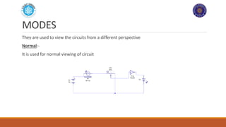
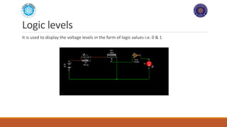
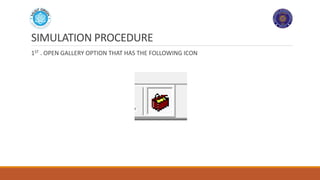
GUIDE TO LIVE WIRE
AND PCB WIZARD
BY ABDULLAH ARIF(Electrical 5th)
WORK SHOP ORGANIZED BY
ORION
MUST, MIPRUR AJK
Circuit to be designed:-
The circuit we will design is
Auto night switch using LDR(light dependent resistor) circuit
It depends on following components
1)BATTERY
2)LDR
3)POTETIOMETER
4)LED
5)NOT GATE(7404)
Battery
The Battery we will use here is 9volts DC battery
The reason to use this battery is for the simplicity of this circuit
You can use any type of voltage source available but it may change the appearance of your
circuit
LDR
LDR
An LDR is a component that has a (variable) resistance that changes with the light intensity that
falls upon it. This allows them to be used in light sensing circuits.
Potentiometer
A potentiometer is a three-terminal resistor with a sliding or rotating contact that forms an
adjustable voltage divider. If only two terminals are used, one end and the wiper, it acts as a
variable resistor or rheostat.
Potentiometers are commonly used to control electrical
devices such as volume controls on audio equipment.
Potentiometers operated by a mechanism can be used
as position transducers, for example, in a joystick.
Potentiometers are rarely used to directly control
significant power (more than a watt), since the power
dissipated in the potentiometer would be comparable
to the power in the controlled load.
Not gate 7404
In digital logic, an inverter or NOT gate is a logic gate which implements logical negation. The
truth table is shown on the right.
What is LIVEWIRE?
Livewire is a modern and complex software package for designing
and simulating electronic circuits.
Switches, transistors, diodes, integrated circuits and hundreds of
other components can all be connected together to investigate the
behavior of a circuit. There are no limits to what can be designed and
no loose connections or faulty components to worry about.
However, if the maximum ratings for any components are exceeded,
they will explode on screen!
LIVE WIRE
PANEL
USE OF PANEL
It is used to select various options from the program
Modes
MODES
They are used to view the circuits from a different perspective
Normal:-
It is used for normal viewing of circuit
Voltage level
It is used to view the voltage level across any component
It shows the voltage using the red bars, the higher the bar, the larger the voltage
Current Flow
It is used to represent the flow of current through the circuit
Logic levels
It is used to display the voltage levels in the form of logic values i.e. 0 & 1
More
It has different option to choose from
You can use your favorite mode from it!
GALLERY
SIMULATION PROCEDURE
1ST . OPEN GALLERY OPTION THAT HAS THE FOLLOWING ICON
CHOOSE THE RIGHT EQUIPMENT
CHOOSE THE FOLLOWING THINGS AND DRAG THEM TO THE MAIN WINDOW
1)BATTERY
2)LDR
3)POTETIOMETER
4)LED
5)NOT GATE(7404)
EQUIPMENT
Where to locate?
Battery is in “power supplies”
LDR and Potentiometers are in “input components”
NOT gate is in “7400 series” option
LED is in “output components”
CONNECTING THE WIRES
CLICK ON EITHER END OF THE COMPONENT TO EXTEND A WIRE, THEN CONNECT IT TO MAKE A
PATH FOR CURRENT
RUN THE SIMULATION
CLICK ON THE FOLLOWING ICON TO START THE SIMULATION(BLUE PLAY BUTTON)
Intro to PCB wizard
PCB Wizard is a powerful package for designing single-sided and double-sided printed circuit
boards (PCBs).
It provides a comprehensive range of tools covering all the traditional steps in PCB production,
including schematic drawing, schematic capture, component placement, automatic routing, Bill
of Materials reporting and file generation for manufacturing. In addition, PCB Wizard offers a
wealth of clever new features that do away with the steep learning curve normally associated
with PCB packages.
Why not PCB Wizard?
PCB wizard is used here only to create PCB designs for your circuit because in other cases like
creating the circuits, PCB wizard is difficult to use than Livewire
Live wire is used here just to simulate the circuit and then we convert the original circuit to PCB
wizard
CONVERT TO PCB
CLICK ON TOOLS
FROM TOOL , CLICK ON CONVERT
CLICK ON DESING TO CIRCUIT BOARD
THE FOLLOWING POP UP WILL APPEAR:-
If you choose on yes,
You will be given this!
Purpose
The purpose of using Yes option is rather not useful in beginner case
Because in this option, you have to specify the size and other measurements in order to
Make your PCB more precise which is very lengthy process
So rather than using this, we prefer NO!!!
CONVERT TO PCB
CONVERT TO PCB
CLICK ON ‘’CONVERT’’ TO START CONVERSION
BEFORE CONVERSION, YOU MUST OPEN PCB WIZARD TO AUTOMATICALLY TRANSFER THE
CIRCUIT TO THE SOFTWARE
Naming the components
Use this highlighted button to open a dialogue box.you can write in it!!
Dialogue box
Font arrangement
The font will appear reflected because when the font are imprinted on the pcb,they will undergo
a process of mirroring and will give the final result correctly
It is in the programming that will convert your wordings to reflected version
Lastly!!!
Press Ctrl+P to start printing
You should Have the PCB wizard in your USB in order to print it from shops because the source
files of this program can only be opened by this program ony
Point to ponder!
Do not try to Zoom in or out your circuit before printing because it will cause the circuit
components to be far apart and will increase the length B/W the terminals of the components
Most preferable papers are
A4 110 g
Butter paper (sometype of sticky paper)
It will let you convert your circuit on the pcb easily
HOME ASSIGNMENT
1) CREATE THE FIRST WORD OF YOUR NAME USING FLASHING LEDS AND TURN THEM ON AND
OFF USING LDR
2) MAKE LED FLASHER CIRCUIT(REFER TO INTERNET)
THANKYOU
MUST ORION MIRPUR AJK

Guide to live wire and pcb wizard

  • 1.
    GUIDE TO LIVEWIRE AND PCB WIZARD BY ABDULLAH ARIF(Electrical 5th) WORK SHOP ORGANIZED BY ORION MUST, MIPRUR AJK
  • 2.
    Circuit to bedesigned:- The circuit we will design is Auto night switch using LDR(light dependent resistor) circuit It depends on following components 1)BATTERY 2)LDR 3)POTETIOMETER 4)LED 5)NOT GATE(7404)
  • 3.
    Battery The Battery wewill use here is 9volts DC battery The reason to use this battery is for the simplicity of this circuit You can use any type of voltage source available but it may change the appearance of your circuit
  • 4.
  • 5.
    LDR An LDR isa component that has a (variable) resistance that changes with the light intensity that falls upon it. This allows them to be used in light sensing circuits.
  • 6.
    Potentiometer A potentiometer isa three-terminal resistor with a sliding or rotating contact that forms an adjustable voltage divider. If only two terminals are used, one end and the wiper, it acts as a variable resistor or rheostat. Potentiometers are commonly used to control electrical devices such as volume controls on audio equipment. Potentiometers operated by a mechanism can be used as position transducers, for example, in a joystick. Potentiometers are rarely used to directly control significant power (more than a watt), since the power dissipated in the potentiometer would be comparable to the power in the controlled load.
  • 7.
    Not gate 7404 Indigital logic, an inverter or NOT gate is a logic gate which implements logical negation. The truth table is shown on the right.
  • 8.
    What is LIVEWIRE? Livewireis a modern and complex software package for designing and simulating electronic circuits. Switches, transistors, diodes, integrated circuits and hundreds of other components can all be connected together to investigate the behavior of a circuit. There are no limits to what can be designed and no loose connections or faulty components to worry about. However, if the maximum ratings for any components are exceeded, they will explode on screen!
  • 9.
  • 10.
  • 11.
    USE OF PANEL Itis used to select various options from the program
  • 12.
  • 13.
    MODES They are usedto view the circuits from a different perspective Normal:- It is used for normal viewing of circuit
  • 14.
    Voltage level It isused to view the voltage level across any component It shows the voltage using the red bars, the higher the bar, the larger the voltage
  • 15.
    Current Flow It isused to represent the flow of current through the circuit
  • 16.
    Logic levels It isused to display the voltage levels in the form of logic values i.e. 0 & 1
  • 17.
    More It has differentoption to choose from You can use your favorite mode from it!
  • 18.
  • 19.
    SIMULATION PROCEDURE 1ST .OPEN GALLERY OPTION THAT HAS THE FOLLOWING ICON
  • 20.
    CHOOSE THE RIGHTEQUIPMENT CHOOSE THE FOLLOWING THINGS AND DRAG THEM TO THE MAIN WINDOW 1)BATTERY 2)LDR 3)POTETIOMETER 4)LED 5)NOT GATE(7404)
  • 21.
  • 22.
    Where to locate? Batteryis in “power supplies” LDR and Potentiometers are in “input components” NOT gate is in “7400 series” option LED is in “output components”
  • 23.
    CONNECTING THE WIRES CLICKON EITHER END OF THE COMPONENT TO EXTEND A WIRE, THEN CONNECT IT TO MAKE A PATH FOR CURRENT
  • 24.
    RUN THE SIMULATION CLICKON THE FOLLOWING ICON TO START THE SIMULATION(BLUE PLAY BUTTON)
  • 25.
    Intro to PCBwizard PCB Wizard is a powerful package for designing single-sided and double-sided printed circuit boards (PCBs). It provides a comprehensive range of tools covering all the traditional steps in PCB production, including schematic drawing, schematic capture, component placement, automatic routing, Bill of Materials reporting and file generation for manufacturing. In addition, PCB Wizard offers a wealth of clever new features that do away with the steep learning curve normally associated with PCB packages.
  • 27.
    Why not PCBWizard? PCB wizard is used here only to create PCB designs for your circuit because in other cases like creating the circuits, PCB wizard is difficult to use than Livewire Live wire is used here just to simulate the circuit and then we convert the original circuit to PCB wizard
  • 28.
    CONVERT TO PCB CLICKON TOOLS FROM TOOL , CLICK ON CONVERT CLICK ON DESING TO CIRCUIT BOARD THE FOLLOWING POP UP WILL APPEAR:-
  • 29.
    If you chooseon yes, You will be given this!
  • 30.
    Purpose The purpose ofusing Yes option is rather not useful in beginner case Because in this option, you have to specify the size and other measurements in order to Make your PCB more precise which is very lengthy process So rather than using this, we prefer NO!!!
  • 31.
  • 32.
    CONVERT TO PCB CLICKON ‘’CONVERT’’ TO START CONVERSION BEFORE CONVERSION, YOU MUST OPEN PCB WIZARD TO AUTOMATICALLY TRANSFER THE CIRCUIT TO THE SOFTWARE
  • 33.
    Naming the components Usethis highlighted button to open a dialogue box.you can write in it!!
  • 34.
  • 35.
    Font arrangement The fontwill appear reflected because when the font are imprinted on the pcb,they will undergo a process of mirroring and will give the final result correctly It is in the programming that will convert your wordings to reflected version
  • 36.
    Lastly!!! Press Ctrl+P tostart printing You should Have the PCB wizard in your USB in order to print it from shops because the source files of this program can only be opened by this program ony
  • 37.
    Point to ponder! Donot try to Zoom in or out your circuit before printing because it will cause the circuit components to be far apart and will increase the length B/W the terminals of the components Most preferable papers are A4 110 g Butter paper (sometype of sticky paper) It will let you convert your circuit on the pcb easily
  • 38.
    HOME ASSIGNMENT 1) CREATETHE FIRST WORD OF YOUR NAME USING FLASHING LEDS AND TURN THEM ON AND OFF USING LDR 2) MAKE LED FLASHER CIRCUIT(REFER TO INTERNET)
  • 39.