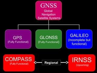
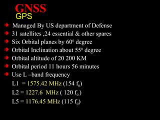
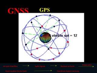
GNSS
GPS
Managed By USdepartment of Defense
31 satellites ,24 essential & other spares
Six Orbital planes by 600
degree
Orbital Inclination about 550
degree
Orbital altitude of 20 200 KM
Orbital period 11 hours 56 minutes
Use L –band frequency
L1 = 1575.42 MHz (154 f0)
L2 = 1227.6 MHz ( 120 f0 )
L5 = 1176.45 MHz (115 f0)
5.
GNSS
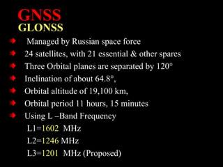
GLONSS
Managed by Russianspace force
24 satellites, with 21 essential & other spares
Three Orbital planes are separated by 120°
Inclination of about 64.8°,
Orbital altitude of 19,100 km,
Orbital period 11 hours, 15 minutes
Using L –Band Frequency
L1=1602 MHz
L2=1246 MHz
L3=1201 MHz (Proposed)
6.
GNSS
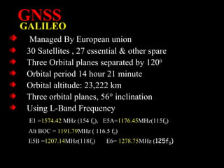
GALILEO
Managed By Europeanunion
30 Satellites , 27 essential & other spare
Three Orbital planes separated by 1200
Orbital period 14 hour 21 minute
Orbital altitude: 23,222 km
Three orbital planes, 56° inclination
Using L-Band Frequency
E1 =1574.42 MHz (154 f0), E5A=1176.45MHz(115f0)
Alt BOC = 1191.79MHz ( 116.5 f0)
E5B =1207.14MHz(118f0) E6= 1278.75MHz (125f0)
7.
GNSS
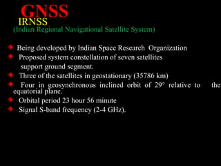
IRNSS
(Indian Regional NavigationalSatellite System)
Being developed by Indian Space Research Organization
Proposed system constellation of seven satellites
support ground segment.
Three of the satellites in geostationary (35786 km)
Four in geosynchronous inclined orbit of 29° relative to the
equatorial plane.
Orbital period 23 hour 56 minute
Signal S-band frequency (2-4 GHz).
8.
GPS
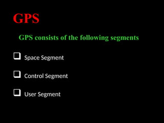
GPS consists ofthe following segments
Space Segment
Control Segment
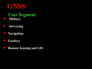
User Segment
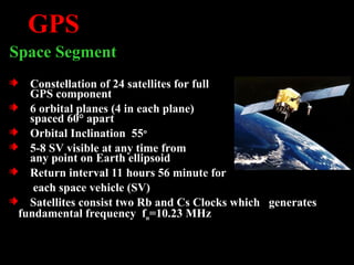
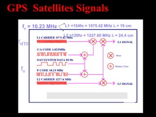
GPS
Space Segment
Constellation of24 satellites for full
GPS component
6 orbital planes (4 in each plane)
spaced 60° apart
Orbital Inclination 55o
5-8 SV visible at any time from
any point on Earth ellipsoid
Return interval 11 hours 56 minute for
each space vehicle (SV)
Satellites consist two Rb and Cs Clocks which generates
fundamental frequency fo=10.23 MHz
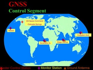
GNSS
Control Segment
US SpaceCommand
Colorado Springs
Hawaii
Ascension Is.
Diego Garcia
Kwajalein Atoll
Monitor Station Ground Antenna
Master Control Station
GNSS
Two Basic Functionsof GPS
Position, which is basic utility in our daily life
Our Magic Numbers are
Longitude, Latitude &Altitude
Accurate time measurement.
15.
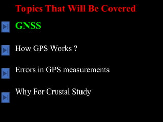
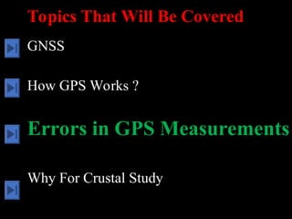
Topics That WillBe Covered
GNSS
How GPS Works ?
Errors in GPS Measurements
Why For Crustal Study
16.
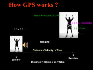
How GPS works?
1 2 3 4 5 6……
1 2 3 4 5 6……
1 2 3 4 5 6……
1 2 3 4 5 6…Correlated
S
Satellite
R
Receiver
Distance =Velocity x Time
Distance = 330m/s x 3s =990m
Basic Principle Of GPS
Ranging
3sec
17.
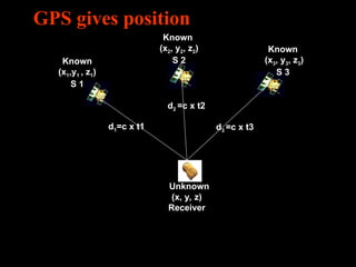
GPS gives position
Known
(x1,y1, z1)
S 1
Known
(x3, y3, z3)
S 3
Known
(x2, y2, z2)
S 2
Unknown
(x, y, z)
Receiver
d1=c x t1
d2 =c x t2
d3 =c x t3
18.
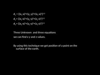
d1 = {(x1-x)2
+(y1-y)2
+(x1-x)2
}1/2
d2= {(x2-x)2
+(y2-y)2
+(z2-z)2
}1/2
d3 = {(x3-x)2
+(y3-y)2
+(z3-z)2
}1/2
Three Unknown and three equations
we can find x y and z values.
By using this technique we get position of a point on the
surface of the earth.
19.
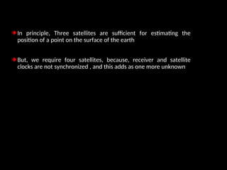
In principle, Threesatellites are sufficient for estimating the
position of a point on the surface of the earth
But, we require four satellites, because, receiver and satellite
clocks are not synchronized , and this adds as one more unknown
20.
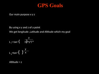
Our main purposex y z
By using x y and z of a point
We get longitude ,Latitude and Altitude which my goal
L t= tan-1
( )
L g=tan-1
( )
Altitude = z
z
(x2
+y2
)1/2
y
x
GPS Goals
21.
Topics That WillBe Covered
GNSS
How GPS Works ?
Errors in GPS Measurements
Why For Crustal Study
22.
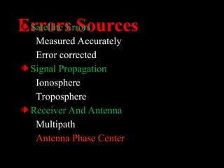
Errors Sources
Satellite Errors
MeasuredAccurately
Error corrected
Signal Propagation
Ionosphere
Troposphere
Receiver And Antenna
Multipath
Antenna Phase Center
23.
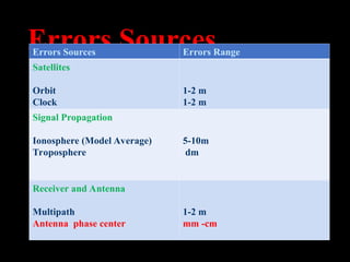
Errors Sources
Errors SourcesErrors Range
Satellites
Orbit
Clock
1-2 m
1-2 m
Signal Propagation
Ionosphere (Model Average)
Troposphere
5-10m
dm
Receiver and Antenna
Multipath
Antenna phase center
1-2 m
mm -cm
24.
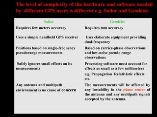
Sailor Geodeist
Requires fewmeters accuracy Requires mm accuracy
Uses a simple handheld GPS receiver Uses elaborate equipment providing
dual-frequency
Positions based on single-frequency
pseudorange measurements
Based on carrier-phase observations
and low-noise pseudo range
observations
Safely ignores small effects on its
measurements
Processing software must account for
effects as small as a few millimeters
e.g. Propagation Relativistic effects
etc.
Any antenna and multipath
environment is no cause of concern
The measurements will be affected by
any instability in the phase center of
the antenna and any multipath signals
accepted by the antenna.
The level of complexity of the hardware and software needed
by different GPS users is different e.g. Sailor and Geodeist.
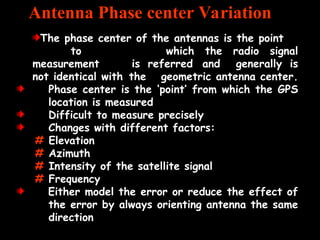
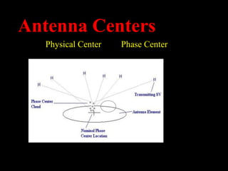
The phase centerof the antennas is the point
to which the radio signal
measurement is referred and generally is
not identical with the geometric antenna center.
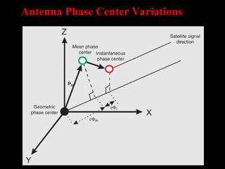
Phase center is the ‘point’ from which the GPS
location is measured
Difficult to measure precisely
Changes with different factors:
# Elevation
# Azimuth
# Intensity of the satellite signal
# Frequency
Either model the error or reduce the effect of
the error by always orienting antenna the same
direction
Antenna Phase center Variation
27.
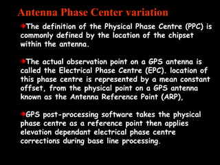
The definition ofthe Physical Phase Centre (PPC) is
commonly defined by the location of the chipset
within the antenna.
The actual observation point on a GPS antenna is
called the Electrical Phase Centre (EPC). location of
this phase centre is represented by a mean constant
offset, from the physical point on a GPS antenna
known as the Antenna Reference Point (ARP),
GPS post-processing software takes the physical
phase centre as a reference point then applies
elevation dependant electrical phase centre
corrections during base line processing.
Antenna Phase Center variation
28.
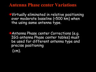
Antenna Phase centerVariations
Virtually eliminated in relative positioning
over moderate baseline (<500 km) when
the using same antenna type.
Antenna Phase center Corrections (e.g.
IGS antenna Phase center tables) must
be used for different antenna type and
precise positioning
(cm).
29.
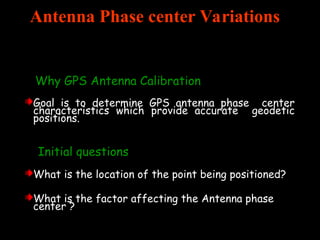
Antenna Phase centerVariations
Why GPS Antenna Calibration
Goal is to determine GPS antenna phase center
characteristics which provide accurate geodetic
positions.
Initial questions
What is the location of the point being positioned?
What is the factor affecting the Antenna phase
center ?
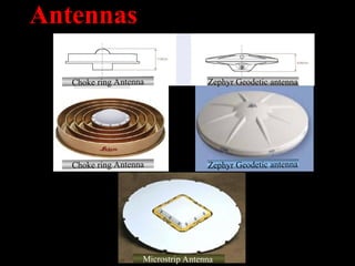
Antennas
Choke ring AntennaZephyr Geodetic antenna
Microstrip Antenna
Choke ring Antenna Zephyr Geodetic antenna
33.
Topics That WillBe Covered
GNSS
How GPS Works ?
Errors in GPS Measurements
Why For Crustal Study
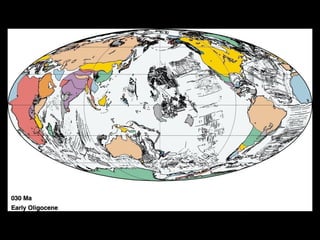
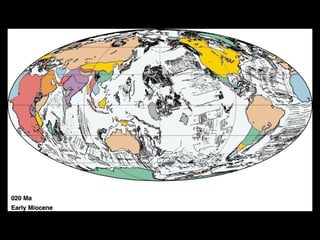
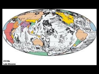
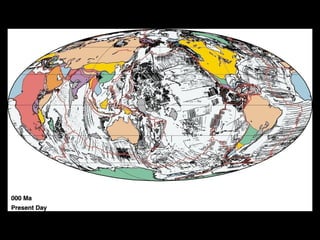
53.
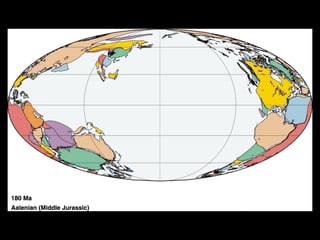
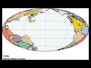
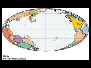
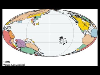
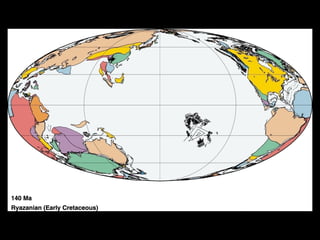
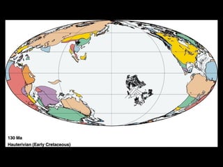
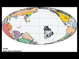
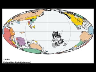
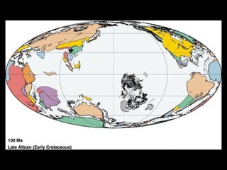
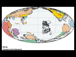
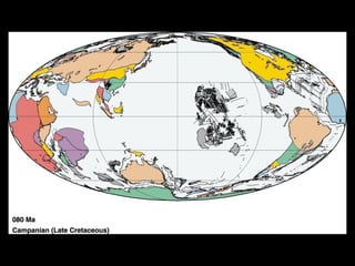
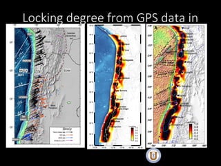
Crustal Deformation
Every crustalplate is moving in random
direction With very low speed in cm
range.
We can not measure it globally.
GNSS is only tool which can provide to
estimate low velocities of these crustal
plates.
54.
Conclusion
A phase centermay vary and can be
estimated
An offset and phase center variation
(PCV) must be applied to yield correct
distance to the source
Different phase centers, when corrected
for offset and PCV give identical results
There is no phase center for which PCV is
zero but can be minimized
55.
Conclusion…
Antennas that aremanufactured the same
Antennas that are manufactured the same
way will usually have the phase center
way will usually have the phase center
in the same place.
in the same place.
In requiring extreme accuracy, the same
In requiring extreme accuracy, the same
model of antenna will be used on both the
model of antenna will be used on both the
base station and the rover. Each antenna
base station and the rover. Each antenna
is then aimed north to insure that the
is then aimed north to insure that the
phase center of each antenna is located in
phase center of each antenna is located in
the same place with respect to each other
the same place with respect to each other
every time.
every time.
Seismic cycle
Seismic cycle
Reid,
[1910]
coseismiccoseismic
interseismic
post
seismic
permanent
deformation
displacement
time
(A)
(B)
(C)
Ideal seismic
cycle
(elastic
behaviour)
Observed seismic cycle
(Viscoelastics
behaviour)
coseismic coseismic
interseismic
displacement
time
coseismic coseismic
interseismic
post
seismic
permanent
deformation
displacement
time
59.
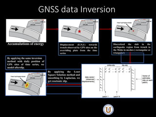
Interseismic
Accumulations of energy
Coseismic
Displacement(E,N,U) towards
trench observed by GPS sites on the
overriding plate from the time
series
Discretized the slab in the
earthquake region from trench to
the Moho in meshes ( rectangular or
triangular)
i
j
j s
G
u
u
C
G
G
C
G
s u
T
u
T 1
1
1
ˆ
By applying the Least
Square Solution method and
smoothing by Laplacian, we
get coseismic slip.
By applying the same inversion
method with daily position of
GPS sites of time series, we
model afterslip.
GNSS data Inversion

![Asperity model and deformation
pattern
Lay, [2015]](https://image.slidesharecdn.com/gpstechnique-250807021052-406d2590/85/GPS-technique-57-320.jpg)
![Seismic cycle
Seismic cycle
Reid,
[1910]
coseismic coseismic
interseismic
post
seismic
permanent
deformation
displacement
time
(A)
(B)
(C)
Ideal seismic
cycle
(elastic
behaviour)
Observed seismic cycle
(Viscoelastics
behaviour)
coseismic coseismic
interseismic
displacement
time
coseismic coseismic
interseismic
post
seismic
permanent
deformation
displacement
time](https://image.slidesharecdn.com/gpstechnique-250807021052-406d2590/85/GPS-technique-58-320.jpg)


![20260201 [FOSDEM] gomodjail - library sandboxing for Go modules.pdf](https://cdn.slidesharecdn.com/ss_thumbnails/20260201fosdemgomodjail-librarysandboxingforgomodules-260201225659-76609ec4-thumbnail.jpg?width=640&height=640&fit=bounds)


![谷歌留痕技术教程[ 𝙩𝙤𝙥 𝟮𝟯𝟯. 𝙘 𝙤𝙢 ]](https://cdn.slidesharecdn.com/ss_thumbnails/top233-260130173900-2eb784f9-thumbnail.jpg?width=640&height=640&fit=bounds)


