This document provides an overview and contact information for Go Power Systems, a manufacturer of dynamometers. It includes:
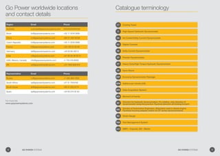
- Contact details for Go Power Systems global headquarters and regional representatives.
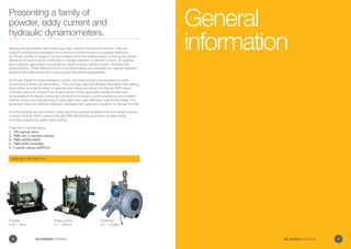
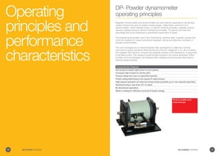
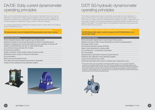
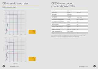
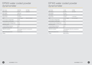
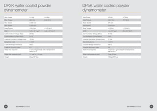
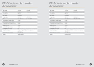
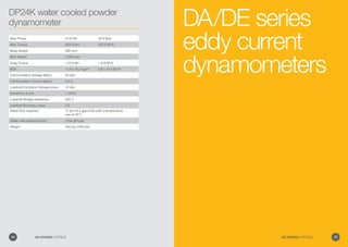
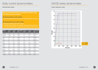
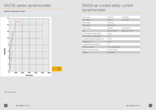
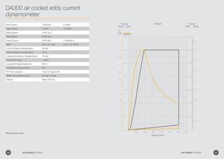
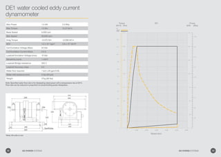
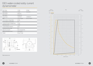
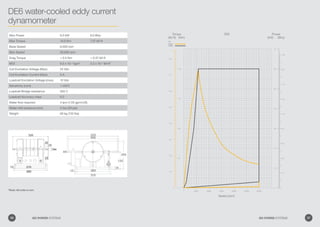
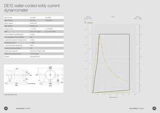
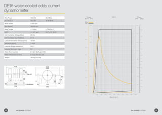
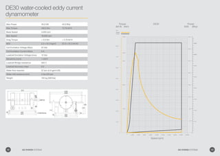
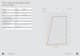
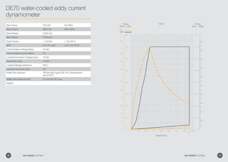
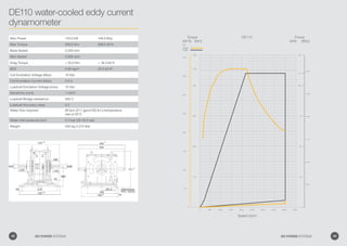
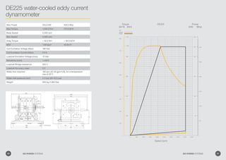
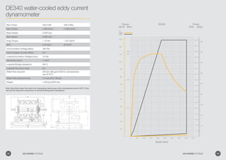
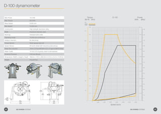
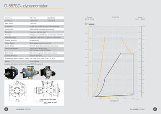
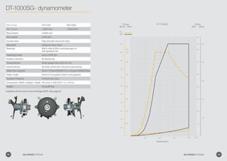
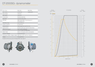
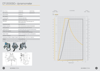
- Descriptions of the different types of dynamometers produced - powder, eddy current, and hydraulic dynamometers, along with their typical applications and specifications.
- Information on Go Power Systems' product catalog, which provides specifications and details on their individual dynamometer models.
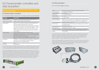
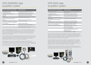
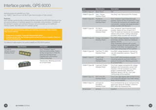
- Additional services and accessories offered to support dynamometer installation and operation.
This document discusses the function and biomechanics of the hip joint. It describes the three motions of the hip joint - flexion/extension, abduction/adduction, and medial/lateral rotation - as movements of the femoral head within the acetabulum. It also discusses pelvic motions including anterior/posterior tilt, lateral tilt, and anterior/posterior rotation which produce the same motions at the hip joint. Compensatory lumbar spine motions that accompany various pelvic motions in weight-bearing are also described.
Mohr's circle is a graphical representation of the transformation of stress tensors under a change of coordinates. It depicts the normal and shear stresses on a plane rotated by some angle θ from the original plane. The center of the Mohr circle represents the average normal stress, and the radius represents the maximum shear stress. Rotating the plane by θ degrees corresponds to moving around the Mohr circle by 2θ degrees. Mohr's circle provides a simple way to analyze stresses at a point within a material.
Hyster n006 (h7.0 fts6) forklift service repair manualhhjsekmdmm
This document provides specifications and service information for Hyster lift truck models, including:
- Lift capacities and counterweight weights for various models
- Tire sizes, fuel capacities, fluid capacities, and recommended fluids
- Electrical system specifications such as battery size and alternator output
- Transmission oil pressures and hydraulic system relief pressures
- Instructions for removing the drive axle, which include draining fluids and disconnecting brake and hydraulic lines
Volvo ec160 b nlc ec160bnlc excavator service repair manualfjjskekksemmm
The document provides information on servicing a track gearbox, including:
1. The track gearbox consists of a two-stage planetary gear mechanism that converts high-speed motor rotation into low-speed, high-torque rotation to power the sprocket.
2. Proper lubrication and maintenance procedures are outlined, including recommended oil type and replacement schedule.
3. Troubleshooting tips are provided for issues like abnormal noise, temperature, or leakage. Removal and installation steps are described.
The document outlines the elements of an osteopathic manual therapy (OMT) evaluation. It describes the screening exam, detailed exam components including history, inspection, tests of function, palpation, and neurologic/vascular exams. It then discusses medical diagnostic studies, diagnosis/trial treatment, and various OMT treatment approaches to relieve symptoms, increase mobility, limit movement, and educate patients. Key elements are screening exams to identify problem regions, detailed exams to diagnose musculoskeletal issues treatable with OMT, and customized OMT plans to address patients' signs, symptoms, and stage of pathology.
Proprioceptive neuromuscular facilitation (PNF) is an exercise technique based on principles of neurophysiology and functional anatomy. It uses patterns of diagonal movements combining flexion, extension, abduction, adduction, and rotation. The 9 principles of PNF include resistance, stretch, timing, and verbal commands. PNF techniques like repeated contractions and hold-relax are used to improve areas like strength, flexibility, and motor control by facilitating agonist and antagonist muscle groups. PNF patterns involve multi-joint diagonal movements of the upper and lower extremities.
The document discusses lubrication and its types. It defines lubrication as reducing friction between surfaces in contact by interposing a lubricant. There are several types of lubrication depending on the motion between surfaces, including hydrodynamic lubrication which uses fluid pressure to separate surfaces, boundary lubrication where the film is too thin to separate surfaces, and mixed lubrication which is a transition between the two. Extreme pressure lubrication uses additives that react when heated to form protective surface films. Proper lubrication reduces wear, heat, energy consumption, and increases machinery life.
This document discusses moments of inertia, which are a measure of an object's resistance to rotational acceleration about an axis. It defines the moment of inertia of an area and introduces key concepts like the parallel axis theorem, radius of gyration, and calculating moments of inertia through integration or for composite areas. Examples are provided to demonstrate calculating moments of inertia for various shapes, including rectangles, triangles, L-shapes, and composite profiles, about different axes. The document also covers determining moments of inertia at the centroidal axes versus other axes using the parallel axis theorem.
Ekeeda Provides Online Civil Engineering Degree Subjects Courses, Video Lectures for All Engineering Universities. Video Tutorials Covers Subjects of Mechanical Engineering Degree.
This document discusses the stress-strain curve for textile fibers. It defines stress as the force per unit area applied to a material, and strain as the increase in length from an applied stress. A typical stress-strain curve shows four regions: the elastic region where deformation is recoverable, yielding where permanent deformation begins, strain hardening where the curve rises continuously, and necking and failure where the material fractures.
The document discusses the concept of center of gravity and factors that affect balance. It defines center of gravity as the point where the weight of a body is considered to act. It is affected by a body's mass distribution, weight, shape, and position of its base of support. Maintaining a center of gravity over the base of support within a body's limits allows for optimal balance, stability, and efficient motion.
After acl-reconstruction - POSTSURGICAL ACL REHABILITATION PROTOCOLpriyaakumarr
This is an outline of the major exercises that are commonly incorporated. Individual patient response should be considered and therefore modifications may need to be made. Communication should be made to the Surgeon if concerns arise during rehabilitation.
To Know more visit - http://www.dramrajani.com/
Composition of synovial fluid and mechanism of joint lubricationBipulBorthakur
Synovial fluid is produced by synoviocytes in synovial joints and has several important functions. It lubricates and reduces friction between cartilage surfaces, acts as a shock absorber, and provides nutrients to cartilage. Synovial fluid composition includes hyaluronic acid, which increases viscosity and lubricates, and lubricin, which is responsible for boundary layer lubrication. Joint lubrication occurs through several mechanisms - fluid film lubrication involves hydrodynamic and squeeze film actions that generate pressure films, boundary lubrication uses an adsorbed lubricant layer, and mixed lubrication is a combination utilizing both fluid film and boundary layers.
The stress-strain curve shows the relationship between stress and strain for a material. It reveals properties like Young's modulus, yield strength, and ultimate tensile strength. The elastic limit is the maximum stress where the material fully recovers after unloading. The yield point marks the transition from elastic to plastic behavior. For some materials without a clear yield point, the 0.2% offset method is used to determine the yield strength. After yielding, strain hardening causes the material's strength to increase with more deformation until it reaches its ultimate strength and fractures.
This topic contains the core topic in Biomechanics which serves as the foundation for curriculum of Undergraduate and Post graduate Physiotherapy students.This presentation aims at the clarification of foundational concepts.
Posture is related to the word position. How we stand, walk or sit. Correct posture means when the weight is properly divided on all parts of the body. You seem balanced. When there is a slight imbalance, postural deformity occurs. Postural deformities are a reason for low esteem in many people. They feel uncomfortable and awkward among people. It affects them not only emotionally but physically too. They are unable to walk or run properly. They can`t stand straight. Yoga has been an integral part of India`s heritage. It proves to be beneficial for people who have postural deformities. The effects are not seen within a day or two but with regular practice people can correct their postures.
Numericals on Columns and struts_-_solvedViriSharma
This document contains 7 problems related to calculating the load capacity of steel columns using Euler's theory and Rankine's formula. Problem 1 compares the strength ratio of a solid vs hollow steel column. Problem 2 calculates the safe load for a solid round bar column with different end conditions. Problem 3 finds the strength ratio of a solid vs hollow steel column with the same cross-sectional area. Problem 4 calculates the Euler crushing load and compares it to Rankine's formula. Problems 5-7 involve calculating column load capacities for various steel sections using Euler, Rankine, and IS code methods.
This document presents an overview of selected resistance training regimens, including progressive resistance exercise, circuit weight training, and isokinetic training. It describes progressive resistance exercise regimens like the Delorme and Oxford models which gradually increase weight loads over sets. Circuit weight training involves continuous exercises performed at stations targeting major muscle groups. Isokinetic training maintains a constant velocity of movement using specialized machines, typically starting at medium speeds for rehabilitation.
Hyster b010 (s25 xl) forklift service repair manualufjjsjefkskekmme
This document provides information on servicing the steering axle assembly of a lift truck. It describes the main components of the steering axle, including the axle frame, steering cylinder, spindle assemblies, and wheel hubs. The steering cylinder uses hydraulic pressure to rotate the axle from side to side via tie rods connected to the spindle arms. Proper preload is maintained on the spindle and wheel hub bearings using king pins and castle nuts respectively. Safety warnings are also provided for putting the lift truck on blocks during maintenance and repairs.
This document provides an overview of biomechanics and its key concepts. It begins by defining biomechanics as the application of mechanical principles to the study of living organisms. It then discusses the importance of biomechanics in understanding forces on the body, improving devices, and informing treatments. The document outlines key biomechanics topics like kinematics, kinetics, arthrokinematics, and kinetic chains. It provides examples of each concept and their clinical relevance. In summary, the document introduces biomechanics and surveys its fundamental terms and applications.
Taping is a technique used to support injured soft tissues and joints by restricting motion and providing compression. It has several goals including restricting injured joint motion, compressing tissues to reduce swelling, and supporting injured structures. There are different types of tape including stretch tapes that conform to the body and non-stretch tapes that provide support. Proper skin preparation, tape application technique, and removal are important to avoid further injury and allow for healing. Taping can aid the rehabilitation process and allow safe return to activity.
The document discusses thick cylinders where the radial stress is significant and not uniform. It presents Lame's equations, which relate the radial, circumferential, and longitudinal stresses. The equations are derived considering equilibrium of forces on a differential cylinder wall element. Radial and circumferential stresses vary parabolically according to Lame's equations. Three example problems are included to demonstrate calculating stresses in thick cylinders under internal and external pressures using the equations.
The document summarizes the biomechanics of the lumbar spine. It describes the anatomy including the vertebrae, discs, curves, and ligaments. It discusses the movements including flexion, extension, lateral flexion, and rotation. It also outlines the kinetics and kinematics of compression, shear, and the various motions. Common conditions like lumbar lordosis are explained. Range of motion values and an example case study on lumbar stenosis are provided. Physiotherapy management focuses on strengthening the core and avoiding extension.
The Sun RAM 3000 Chassis Dynamometer is available in 260 kW or 360 kW configurations for vehicle testing. It uses an eddy current brake and mobile PC platform to control comprehensive test programs. Tests include maximum power, constant speed, power curve, tachometer accuracy, and load simulation. Measurements of speed, temperature, RPM and other values are displayed. The dynamometer provides a controlled environment to evaluate vehicle performance and fuel efficiency.
This document discusses modeling mechanical systems using three basic elements: springs, dampers, and masses. It describes the properties and dynamic responses of ideal spring and damper elements and provides examples of real-world springs and dampers. The document also discusses modeling nonlinear springs and damping effects in mechanical systems.
We manufacture various Dynamometers to test Automobile gearboxes,Industrial gearboxes,Geared motors, Gear reducers, gear transmissions, etc
Torque: 1 Nm to 10000 Nm
Speed: 1 RPM to 1500 RPM.
Manual Dynamometer Control: To Set Braking Torque & read Torque, Speed, KW/HP on Digital Indicators.
Computerized Control: Torque Loading, Speed Control thru PC, Captured data on Torque, Speed, Power, Temperature, Time, etc is stored in MS Excel in Tabular form & custom curves between Torque, Speed, Power, Temperature, Time, Torque, Speed, Power, Temperature, or custom curves, plotted & exported to Excel.
Test Benches, for testing Performance & Endurance testing of Engines, Motors, Shafts & Axles, Gear Boxes, Automobile Gear Transmissions, Chassis, etc..
Test Beds with T slots having X, Y axis adjustment for Length, Width, & Z axis adjustments for Height. Height adjustment is either Motorized or by Mechanical Jacks. with Anti Vibration mountings are offered along with dynamometers
Dynamometers are devices used to measure torque and power. There are two main types: absorption dynamometers which measure power by absorbing it, and transmission dynamometers which measure torque transmitted through a shaft. Examples of absorption dynamometers include Prony brake, rope brake, and hydraulic dynamometers. Transmission dynamometers include belt transmission, epicyclic gear train, and torsion dynamometers. Torsion dynamometers work by measuring the angle of twist in a shaft which is directly proportional to the transmitted torque.
Introduction to Gears & Dynamometers (Theory of Machines)Ishan Parekh
Gears are used to transmit rotational motion from one shaft to another. The three main types of gears are spur gears, helical gears, and bevel gears. Spur gears have teeth parallel to the axis of rotation and are used to transmit power between parallel shafts. Helical gears are cut at an angle, which allows them to engage more smoothly than spur gears. Bevel gears are used when the direction of shaft rotation needs to change, such as at right angles. Dynamometers are used to measure engine power output. Absorption dynamometers like the Prony brake and rope brake absorb power through friction, while transmission dynamometers measure torque transmitted through a transmission system.
This document discusses different types of dynamometers used to measure brake horsepower in engine testing. It describes absorption dynamometers like the Prony brake, rope brake, and hydraulic dynamometer which absorb and dissipate engine power as heat. Transmission dynamometers are also discussed, including the epicyclic-train, belt transmission, and torsion dynamometers which transmit power to a load for measurement. Specific details are provided on the operation and power measurement equations for several dynamometer types, such as how the Prony brake measures flywheel torque via a supporting weight, and how the epicyclic-train dynamometer uses gear ratios and a lever system to calculate torque and power.
The document discusses gear boxes and their industrial applications. It defines a gear as a cylindrical part with cut teeth that meshes with another gear to transmit torque. A gear box is an assembly that uses gears, shafts, and bearings to reduce speed while increasing torque from a prime mover like an electric motor. Common types of gears and gear boxes are described along with their construction and wide use in industries like manufacturing equipment, material handling, automobiles, cement production, and sugar machinery. In conclusion, gear boxes provide customized speeds and torques required for different machines and processes.
This document provides an overview of transducers. It defines a transducer as a device that converts a non-electrical physical quantity into an electrical signal. Transducers contain a sensing element that produces a measurable response to physical changes and a transduction element that converts the sensor output into an electrical form. Transducers are classified based on their output signal type (analog or digital), application method (primary or secondary), energy conversion method (active or passive), and transduction principle used (resistive, capacitive, inductive, etc.). Examples of common transducers discussed include thermocouples, strain gauges, thermistors, and linear variable differential transformers. Selection factors and applications of transducers
John Deere PowerTech 2.9 L Diesel Engines Service Repair Manual.pdffujjekdmdmd
This document provides an introduction and overview for the PowerTech 2.9 L Diesel Engines Component Technical Manual. It identifies the engines covered in the manual and notes they were produced in France and Mexico. It includes engine application charts organizing the engines by model, series, and emissions certification. Safety messages and the manual's organization into sections on repair, operation, tools and specifications are also summarized. The document outlines revisions made to the manual and emissions regulations the engines may meet depending on destination.
John Deere PowerTech 2.9 L Diesel Engines Service Repair Manual.pdffujskmd9dokk
This document provides an introduction and overview for the PowerTech 2.9 L Diesel Engines Component Technical Manual. It identifies the engines and applications covered by the manual and notes that the manual is intended for experienced technicians. Safety messages and divided into repair, operation, tools and specifications sections. It also provides updates and changes to the manual to discard the previous version.
John Deere PowerTech 2.9 L Diesel Engines Service Repair Manual.pdfpwg56547003
This document provides an overview and summary of repair procedures for PowerTech 2.9 L diesel engines. It begins with introductory information such as engine identification, specifications, and diagrams. It then details procedures organized by major engine systems, including the cylinder head and valves (Group 05), cylinder block (Group 10), crankshaft (Group 15), and other systems. The document emphasizes safety and provides concise instructions for repairs, with references to additional information sources. It aims to equip technicians with the essential guidance for servicing these engines.
John Deere PowerTech 2.9 L Diesel Engines Service Repair Manual.pdfdujdkksmdm
This document provides an overview and summary of repair procedures for PowerTech 2.9 L diesel engines. It begins with introductory information such as engine identification, specifications, and cutaway diagrams. It then outlines procedures grouped by major engine systems, including the cylinder head and valves (Group 05), cylinder block (Group 10), crankshaft (Group 15), and other systems. The document indicates that procedures were updated in the areas of engine break-in, connecting rods, fuel injection pumps, cooling system tests, and more. Safety information is provided in Group 00 and tool references in Groups 200-210.
John Deere PowerTech 2.9 L Diesel Engines Service Repair Manual.pdff8usedkdmdme3
This document provides an overview and repair instructions for PowerTech 2.9 L diesel engines. It begins with general safety information and an introduction to the engine, including identification, specifications, and descriptions. The document is then divided into groups covering specific repair operations and components. The groups include the cylinder head and valves, cylinder block, crankshaft, lubrication system, and more. Detailed instructions are provided for maintenance, overhaul, and repair of engine parts. Specifications and torque values are also included for reference.
John Deere PowerTech 2.9 L Diesel Engines Service Repair Manual.pdff8uejkkdmdm8u
This document provides an introduction and overview for the PowerTech 2.9 L Diesel Engines Component Technical Manual. It identifies the engines covered in the manual and notes they were produced in France and Mexico. It includes engine application charts organizing the engines by model, series, and emissions certification. Safety messages and the manual's organization into sections on repair, operation, tools and specifications are also summarized. The document outlines revisions made to the manual and emissions regulations the engines may meet depending on destination.
John Deere PowerTech 2.9 L Diesel Engines Service Repair Manual.pdfdjfksekmdmdm
This document provides an overview and repair instructions for PowerTech 2.9 L diesel engines. It begins with general safety information and an introduction to the engine, including identification, specifications, and descriptions. The document is then divided into groups covering specific repair areas. Group 05 covers cylinder head and valve repair, including instructions for removing and installing the cylinder head, servicing the valves, checking clearances, and adjusting the valves. The summary provides high-level context about the document and highlights that it contains repair instructions for the cylinder head and valves.
John Deere PowerTech 2.9 L Diesel Engines Service Repair Manual.pdffujseikddmmd3e
This document provides an introduction and overview for the PowerTech 2.9 L Diesel Engines Component Technical Manual. It identifies the engines covered in the manual and notes they were produced in France and Mexico. It includes engine application charts organizing the engines by model, series, and emissions certification. It outlines updates made in new versions of the manual. Finally, it indicates some engines may be certified to meet EPA, CARB, or European emissions standards, and lists tampering with emission components is prohibited.
John deere power tech 2.9 l diesel engines service repair manualfjsekkxszdmmem
This document provides an overview and summary of repair procedures for PowerTech 2.9 L diesel engines. It begins with introductory information such as engine identification, specifications, and diagrams. It then details procedures organized by major engine systems, including the cylinder head and valves (Group 05), cylinder block (Group 10), crankshaft (Group 15), and other systems. The document emphasizes safety and provides concise instructions for repairs, with references to additional information sources. It aims to equip technicians with the essential guidance for servicing these engines.
This manual contains technical information and factory service procedures to maintain John Deere's 544G, 544GH, 544G LL, 544G TC, 624G, and 644G loaders. It includes detailed diagnostics and repair instructions, backed by expert technical knowledge, to help operators get the most out of their John Deere machine. This comprehensive manual is a must-have for service technicians and operators looking to get the best performance out of their John Deere Loaders. It contains reliable, easy-to-understand instructions and technical information to help keep 544G, 544GH, 544G LL, 544G TC, 624G, and 644G Loaders running their best.
The pressure p is defined as:
p = F/A
Where:
p = pressure [N/m2 or Pa]
F = force due to weight [N]
A = area [m2]
The larger the area, the lower the pressure for a given force due to weight. Vice versa,
the smaller the area, the higher the pressure.
Bomag bw 100 ac drum roller service repair manualfjjsekmsmmes
The travel system of the BW 100/120 AD/AC-4 rollers uses a closed hydraulic circuit consisting of an axial piston variable displacement pump, two travel motors, a hydraulic oil filter, and cooler. The pump is directly driven by the engine at a constant speed and incorporates safety elements like relief valves. It provides hydraulic fluid to power the parallel connected travel motors and also to release the integrated motor brakes via charge pressure. The return flow is fed back into the pump to complete the closed circuit.
This document provides specifications for a Peugeot XUD9AI diesel engine, including:
- The engine has 4 cylinders in a vertical inline configuration with a single overhead camshaft and indirect injection.
- Specifications are provided for compression ratio, governor type, engine rotation, crankshaft material, cylinder block/head materials, timing drive components, pistons, lubrication system, filters, cooling system, firing order, and electrical system.
- Detailed specifications are also given for the cylinder head, camshaft, valves, springs, guides, seats, swirl chambers, cylinder/piston dimensions, crankshaft, and tightening torques.
Anderson Greenwood is a world class manufacturer of industrial pressure relief valves, providing protection from system overpressure in vessels, tanks, piping, and other closed systems.
This document provides information about common-rail diesel diagnosis training. It discusses the goals of reducing unnecessary part replacement, reducing troubleshooting time, and improving customer satisfaction. The training covers improving system knowledge, learning diagnostic trouble code detection conditions, and implementing structured troubleshooting procedures. The agenda includes reviewing data lists and case studies, as well as active testing. Additional sections provide overviews of common-rail diesel systems, including their components, fuel control operations, and differences from conventional diesel systems.
John Deere 670B 672B 770B Service Repair Manual.pdfExcavator
John Deere 670B 672B 770B Service Repair Manual.pdf
This manual contains high quality images, circuit diagrams, instructions to help you to maintenance, troubleshooting, diagnostic, and repair your truck
This manual contains high quality images, instructions to help you to troubleshoot, and repair your truck. This document is printable, without restrictions, contains searchable text, bookmarks, crosslinks for easy navigation.
This manual contains high quality images, circuit diagrams, instructions to help you to operate, maintenance, diagnostic, and repair your truck. This document is printable, without restrictions, contains searchable text.
Maintenance
Engine
Control System
Mechanical
Fuel Service Specifications
Emission Control
Intake Exhaust Cooling
Lube
Ignition Starting Charging
Auto Transmission Clutch
Manual Transmission
Transfer Propeller Shaft
Drive Shaft
Differential
Axle Suspension
Tire & Wheel
Brake Control
Brake
Parking Brake
Steering Column
Power Steering
Air Condition
Suppl Restraint System
Seat Belt
Engine Immobilizer
Cruise Control
Wiper & Washer
Door Lock
Meter Audio/Visual
Horn
Windshield/Glass Mirror
Instrument Panel
Seat
Engine Hood/ Door
Exterior & Interior
Electrical
Multiplex/ Can Communication
And much more...
John Deere 772B, 772BH Service Repair Manual.pdfExcavator
John Deere 772B, 772BH Service Repair Manual.pdf
This manual contains high quality images, circuit diagrams, instructions to help you to maintenance, troubleshooting, diagnostic, and repair your truck
This manual contains high quality images, instructions to help you to troubleshoot, and repair your truck. This document is printable, without restrictions, contains searchable text, bookmarks, crosslinks for easy navigation.
This manual contains high quality images, circuit diagrams, instructions to help you to operate, maintenance, diagnostic, and repair your truck. This document is printable, without restrictions, contains searchable text.
Maintenance
Engine
Control System
Mechanical
Fuel Service Specifications
Emission Control
Intake Exhaust Cooling
Lube
Ignition Starting Charging
Auto Transmission Clutch
Manual Transmission
Transfer Propeller Shaft
Drive Shaft
Differential
Axle Suspension
Tire & Wheel
Brake Control
Brake
Parking Brake
Steering Column
Power Steering
Air Condition
Suppl Restraint System
Seat Belt
Engine Immobilizer
Cruise Control
Wiper & Washer
Door Lock
Meter Audio/Visual
Horn
Windshield/Glass Mirror
Instrument Panel
Seat
Engine Hood/ Door
Exterior & Interior
Electrical
Multiplex/ Can Communication
And much more...
This document provides performance data for Caterpillar G3500 industrial gas engines. It includes jacket water pump curves, aftercooler pump curves, block resistance curves, and detailed engine performance data across a range of operating conditions. The performance data sheets specify the engine configuration, rating information, emissions data, heat balance data, and other parameters. The document is intended to allow users to understand engine specifications and appropriately size cooling, fuel, exhaust, and other systems for G3500 engines.
work shop manaul CUMMINS MODEL NTA - 855 -L4hrobertdm
This technical manual provides operation and maintenance instructions for Cummins Model NTA-855-L4 diesel engines. It contains information on prestarting procedures such as priming the fuel system, priming the lubrication system, checking engine oil levels, and checking air and coolant connections. It also provides instructions on starting the engine, engine operation at different speeds, shutdown procedures, and maintenance schedules and checks to perform.
1. Engineered-to-go
Product Catalog
2010-11
Global Headquarters
Go Power Systems
45225 Polaris Court
Plymouth, MI 48170
+1-(734) 416-8000
www.gopowersystems.com
Part of Froude Hofmann
www.froudehofmann.com
Copyright 2010
All Rights Reserved
GO POWER
SYSTEMS
GO POWER
SYSTEMS
Contact us
Australia australia@gopowersystems.com
Brazil br@gopowersystems.com
China cn@gopowersystems.com
Czech Republic br@gopowersystems.com
France fr@gopowersystems.com
Germany de@gopowersystems.com
India in@gopowersystems.com
USA, Mexico, Canada info@gopowersystems.com
UK uk@gopowersystems.com
Representative
Russia ru@gopowersystems.com
South Africa sa@gopowersystems.com
South Korea sk@gopowersystems.com
Spain sp@gopowersystems.com
GO POWER SYSTEMS
2. ContentsWhether you’re investigating the peak
power or the torque curve of an engine,
you need a dynamometer that will meet
your testing needs and provide you
with years of reliable, repeatable results.
Go Power Systems have been
manufacturing eddy current and portable
water-brake dynamometers.
We set industry standards by providing
the most durable products possible.
Engine testers globally have relied on
Go Power Systems since 1958.
Further information from:
www.gopowersystems.com
45225 Polaris Court
Plymouth, MI 48170
+1-(734) 416-8000
Part of Froude Hofmann
www.froudehofmann.com
Copyright 2010
All Rights Reserved
1GO POWER SYSTEMSGO POWER SYSTEMS
GO POWER
SYSTEMS
Presenting a family of powder, eddy current
and hydraulic dynamometers__________________________ 2
Go Power worldwide locationsand contact details_______ 4
Catalogue terminology_______________________________ 5
Unit conversions_____________________________________ 6
Major users_________________________________________ 6
Standard features____________________________________ 7
Service/support_____________________________________ 8
Facility water requirements____________________________ 8
Dynamometer selection______________________________ 8
Typical dynamometer duty curve_______________________ 9
DP- Powder dynamometeroperating principles__________ 11
DA/DE- Eddy current dynamometer operating principles_ 12
D/DT SG hydraulic dynamometeroperating principles___ 13
Water cooled powder dynamometers_________________ 15
Specification table_________________________________ 15
DP series dynamometer_____________________________ 16
Quick selection chart________________________________ 16
DP250 water cooledpowder dynamometer_____________ 17
DP500 water cooled powder dynamometer____________ 18
DP1K5 water cooled powder dynamometer____________ 19
DP3K water cooled powder dynamometer_____________ 20
DP5K water cooled powder dynamometer_____________ 21
DP10K water cooled powder dynamometer____________ 22
DP12K water cooled powder dynamometer____________ 23
DP24K water cooled powder dynamometer____________ 24
Eddy current dynamometers_________________________ 26
Specification table__________________________________ 26
DA/DE series dynamometer__________________________ 27
Quick selection chart________________________________ 27
DA/DE series dynamometer__________________________ 28
Quick selection chart________________________________ 28
DA100 air cooled eddy current dynamometer__________ 29
DA300 air cooled eddy current dynamometer__________ 30
DE1 water cooled eddy current dynamometer__________ 32
DE3 water-cooled eddy current dynamometer__________ 34
DE6 water-cooled eddy current dynamometer__________ 36
DE12 water-cooled eddy current dynamometer_________ 38
DE15 water-cooled eddy current dynamometer_________ 40
DE30 water-cooled eddy current dynamometer_________ 42
DE35 water-cooled eddy current dynamometer_________ 44
DE70 water-cooled eddy current dynamometer_________ 46
DE110 water-cooled eddy current dynamometer_______ 48
DE225 water-cooled eddy current dynamometer_______ 50
DE340 water-cooled eddy current dynamometer_______ 52
Hydraulic dynamometer_____________________________ 55
Specification Table _________________________________ 55
D/DT Series dynamometer___________________________ 56
Quick selection chart________________________________ 56
D/DT Series dynamometer___________________________ 57
Quick selection chart________________________________ 57
D-100 dynamometer series__________________________ 58
Overview__________________________________________ 58
D-57SG dynamometer series________________________ 59
Overview__________________________________________ 59
DT- dynamometer_ _________________________________ 60
Series Overview____________________________________ 60
Engine adaptation for DT series dynamometers:________ 61
D-100 dynamometer________________________________ 62
D-357SG- dynamometer____________________________ 64
Specification_______________________________________ 64
D-557SG- dynamometer____________________________ 66
DT-1000SG- dynamometer__________________________ 68
DT-2000SG- dynamometer__________________________ 70
DT-2000SG- dynamometer__________________________ 72
6.0 Dynamometer controllers and data acquisition______ 74
6.1 Dynamometer controllers_________________________ 74
6.1.1 Dynamometer control unit – for eddy current
dynamometers_____________________________________ 74
6.2 Data acquisition_________________________________ 75
6.2.1 DC-200-digital console_________________________ 75
GPS-2508WSG data acquisition system_______________ 76
GPS-6000 data acquisition system____________________ 77
Interface panels, GPS 6000__________________________ 78
6.2.5 TMS- test management________________________ 80
6.3 EDP- or EDP plus economy dynamometer
selector guide______________________________________ 81
6.3.1 EDP – economy dynamometer package connections_
82
7.0 Ancillaries and optional equipment_________________ 83
7.1 D-100 Series____________________________________ 83
7.1.1 VS-3001 Manual Load Control Valve, D-100 ______ 83
VS-3001 manual load control valve, D-100 ____________ 83
7.2 D-57 series_____________________________________ 84
7.2.1 UKIT 43615-10-357- load cell upgrade kits,
D-57 Series________________________________________ 84
UKIT 43615-10-357- load cell upgrade kits, D-57 series _84
7.2.2 OS-57 oil bearing lubrication system – option_____ 85
OS-57 oil bearing lubrication system – option __________ 85
7.2.3 VS-3101 manual load control valve, 57 series_____ 86
VS-3101 manual load control valve, 57 series __________ 86
7.2.4 D-57 series – input shaft adapter ________________ 87
D-57 series – input shaft adapter _____________________ 87
7.3 DT – series_____________________________________ 88
7.3.1 UKIT 002/003 – load cell upgrade kits, DT series___ 88
UKIT 002/003 – load cell upgrade kits, DT series________ 88
7.3.2 DT – engine flywheel housing spacer block set____ 89
DT – engine flywheel housing spacer block set_________ 89
7.3.3 DS-1000/2000 – testing station, DT series________ 90
DS-1000/2000 – testing station,DT series______________ 90
7.3.4 IFA-D1000/2000 – In-frame adapter, DT series_____ 92
IFA-D1000/2000 – In-frame adapter, DT series__________ 92
7.3.5 VS-3XXXX manual load control valve, DT series____ 93
VS-3XXXX manual load control valve, DT series________ 93
7.4 Other mechanical_______________________________ 94
7.4.1 Stub shafts, DT-1000___________________________ 94
Stub shafts, DT-1000 ________________________________ 94
7.4 Other mechanical_______________________________ 94
7.4.2 Power transmission coupling, DT-1000 ___________ 94
Power transmission coupling, DT-1000 ________________ 94
7.4.3 SAE Adapter Extension Plate SET –AD 2000______ 95
SAE Adapter extension plate SET – AD 2000___________ 95
7.4.4 TDA torsional damper coupling, DT series________ 96
TDA torsional damper coupling,DT series _ ____________ 96
7.4.5 50156-XX flywheel adapter TDA-1,2,3000,
DT series__________________________________________ 96
50156- XX flywheel adapter- TDA-1,2,3000, DT series___ 96
7.4.6 DT-DAK- diesel adapter kit______________________ 97
7.4.7 50186- XX manual transmission- universal
SAE flywheel adapter, DT series______________________ 97
50186- XX manual transmission-universal
SAE flywheel adapter, DT series ______________________ 97
7.5 Engine Cooling__________________________________ 98
7.5.1 CT-102/103-Cooling Tower______________________ 98
CT-102/103-Cooling Tower__________________________ 98
7.5.2 CT-104 – cooling tower _ ______________________100
CT-104 – cooling tower ____________________________100
7.6 Calibration equipment___________________________102
7.6.1 TCA- Torque calibration arm kit –
metric or imperial, D-100_ __________________________102
TCA- torque calibration arm kit –
metric or imperial, D-100_ __________________________102
3. CHOOSE THE BEST FIT
General
information
Presenting a family of
powder, eddy current and
hydraulic dynamometers.
Braking dynamometers are measuring class, electro-mechanical devices. They are
used for artificial load simulation on a variety of prime movers and passive elements.
Go Power Systems’ range of dynamometers serve the testing needs of driving and driven
elements for performance verification or design validation of electric motors, IC engines,
fans, blowers, gear-motor combinations, servo motors, starter motors, clutches and
transmissions. Three different forms of dynamometers are presented for optimal selection
based on the test points and torque-power absorbing requirements.
Go Power System’s have intelligent control units that provide cme excitation to eddy
current and powder dynamometers. The controller uses an infinitely adjustable load setting
input either by potentiometer or external load reference signal. An internal DSP based
controller performs closed-loop torque control of the associated dynamometer and
annunciates limit values. Computer connectivity through a communications port enables
remote control and sequencing of cyclic tests with user-definable, load-time profiles. The
generated data can then be captured, displayed and retrieved in graphic or tabular formats.
For the hydraulic dynamometers, there are three options available from the simple manual
control of the VS-3XXX valves to the full GPS 6000 Data Acquisition System which
provides closed loop water valve control.
There are 4 combinations:
1. VS manual valve
2. TMS-OIL in remote manual
3. TMS w/EPS-6000
4. TMS w/V4 controller
5. F series valves w/EPS-6*
Powder
0.25 – 24kw
Eddy current
0.1 – 340kw
Hydraulic
75 – 1,100kw
2 GO POWER SYSTEMS 3GO POWER SYSTEMS
4. Region Email Phone
Australia australia@gopowersystems.com •••••••••••••••••
Brazil br@gopowersystems.com +55 11 5518 2699
China cn@gopowersystems.com +86 21 339 32230
Czech Republic br@gopowersystems.com +55 11 5518 2699
France fr@gopowersystems.com +33 139 22 30 48
Germany de@gopowersystems.com +49 50 68 462-0
India in@gopowersystems.com +91 99 58 36 00 57
USA, Mexico, Canada info@gopowersystems.com +1 734 416 8000
UK uk@gopowersystems.com +44 1905 856 810
Representative Email Phone
Russia ru@gopowersystems.com +7 495-662-7005
South Africa sa@gopowersystems.com +27 31 7055746
South Korea sk@gopowersystems.com +82 31 203 8773
Spain sp@gopowersystems.com +34 93 274 02 83
Go Power worldwide locations
and contact details
For more info:
www.gopowersystems.com
Catalogue terminology
CT
D
DA
DC
DE
DP
DT
DS
EDP
GPM
GPS
MOI
000
SAE
SAE
TMS
UNITS
SG
Cooling Tower
High Speed Hydraulic Dynamometer
Air Cooled Eddy Current Dynamometer
Digital Console
Eddy Current Dynamometer
Powder Dynamometer
Heavy Duty/High Torque Hydraulic Dynamometer
Dyno Stand
Economy Dynamometer Package
Gallons per minute (US)
Data Acquisition System
Moment of Inertia
Society of Automotive Engineers. (Standard used in diesel engine
Flywheel housing adapter match for DT series dynamometers)
Strain Gauge
Test Management System
(IMP) – Imperial, (SI) – Metric
Direction for hydraulic dynamometers. For rotation, view direction of
dynamometer using this practice: Flywheel direction aft looking forward
4 GO POWER SYSTEMS 5GO POWER SYSTEMS
5. Unit conversions Standard features
Military/Defence Power Generation
Automotive Aerospace
Diesel Agriculture
Truck/Bus Oil/Mining
Fleet Construction
Marine Research & Development
Racing Overhaul/Maintenance
Major users
Torque (T)
1 Nm = .737 lb-ft 1 lb-ft = 1.356 Nm
Power (P)
1 kW = 1.341 Bhp 1 Bhp = 0.746 kW
Power Calculations
P kW = T Nm * N rpm P Bhp = T lb-ft * N rpm
9549.3 5,252
Torque ratings: 0.10 Nm to 4,800 Nm (0.07 lbf-ft) to 3,500 lbf-ft)
Power absorption 100 W to 1,120 kW. (0.13 Bhp to 1,500 Bhp)
Smooth, adjustable braking torque
Low residual torque
Low moment of inertia
Integrated speed & torque sensors.
High-end electronic programmable digital controller
All of our dynamometers are reaction-type force sensing devices. All load cells utilize full
bridge strain gauge technology. The speed is detected using a toothed wheel with an
inductive sensor.
The water-cooled eddy current dynamometers are fitted with integratted sensors to
shutdown and are protected against overheating and loss of water flow.
In summary, it can be generalized that:
Powder Dynamometers
Suitable for low to medium speed loading.
Torque developed extends down to zero speed. Nominal torque specified is limited up to
rated speed.
Can be operated beyond the rated speed at reduced torque levels limited by the power
dissipating capabilities up to the maximum value, separately specified for each rating.
Suitable for horizontal mounting only.
Eddy current Dynamometers
Magnetic flux field is the brake media.
Suitable for all, loading applications.
Specifications refer to the peak torque developed at base speed.. Recommended for IC
engines, motors for testing between mid-high speed ranges, blowers and machines
having turbo characteristics.
Significant torque developed at low speeds
Hydraulic Dynamometers
Water is both the brake and cooling media.
Suitable for high speed or high torque, loading applications. (Series specific).
Specifications refer to the peak torque developed at base speed. Suitable for power
measurement of engines or gearboxes testing peak torque and power.
Refer to ••••• which describes operating principles, characteristics, performance
capabilities and limitations of each type of dynamometer.
6 GO POWER SYSTEMS 7GO POWER SYSTEMS
6. 0
Key
Speed (rpm)
D1000SG
1000 2000 3000 4000 4500
0
300
200
100
500
400
Torque
(lbf-ft) (Nm)
Power
(kW) (Bhp)
350
400
300
250
200
150
100
50
100
200
400
600
800
1000
1200
1356
200
300
400
500
600
700
800
900
1000
Torque
Power
(Y1) Torque
(Nm (lb-ft)
Dynamometer
Model
(Y2) Power
(kW) (Bhp)
Line of constant/
max power
Line of constant/
max torque
Base Speed
Torque curve under
constant/max power
Max speed
Curve of increasing
torque
Drag torque
(X) Speed
Service/support
Contact your nearest Go Power Systems office for service or support.
See page 4 for contact information.
Facility water requirements
Please refer to Frequently asked questions in Sections • and •.
Dynamometer selection
Choosing the right type of dynamometer requires a balance between its absorption
characteristics and those of the prime mover. Go Power Systems understands the loading
limits, speed range and power capabilities.
The following guidelines will help to determine which dynamometer series and model most
suitable for your application.
1. Know the speed-torque characteristics of the engine under test.
It is important that power is simply a calculation that reflects the relationship
between torque and speed throughout the operating range of the engine.
When determining what dynamometer will support your test criteria, you need
to know the peak torque and the speed at which peak torque is developed for
each engine you’ll be testing. This data can usually be obtained through the
engine manufacturer.
2. Know your test points.
3. Choose the dynamometer model.
Plot out your profile test points on a power torque vs. speed duty graph, also
known as a “Duty Curve”. Each series and model dynamometer has a different
absorption characteristic and therefore a different duty curve associated with
its abilities.
Once those parameters are determined, overlay a test profile on the Go Power Systems
dynamometer duty curve. These points should contain a dynamometer curve with
the power and torque to hold or achieve and at the speed ranges.
Typical dynamometer duty curve
Refer to a typical duty curve and nomenclature below, example shows a model
DT-1000SG hydraulic dynamometer duty curve.
8 GO POWER SYSTEMS 9GO POWER SYSTEMS
7. Operating
principles and
performance
characteristics
Picture quality poor
need new pic
Characteristic Features
Set torque is stable right down to zero speed.
Compact high torque-to-inertia ratio.
Torque rating from zero to specified speeds
Power rating determines max speed @ rated torque.
High speed operation at reduced torque levels possible up to max speeds specified.
Residual torque, less than 2% of rated.
Bi-directional operation.
Water-cooling for effective removal of brake energy.
DP- Powder dynamometer
operating principles
Magnetic Particle brakes and dynamometers are well suited for applications demanding
medium torque from zero to medium speed ranges. Unlike Eddy current forms of
dynamometers, which develop torque, on electro-dynamic principles, magnetic particle
devices, develop torque on electro-mechanical principles. This gives it an important
advantage that torque developed is practically independent of speed.
The powder dynamometer uses a fine, free-flowing, stainless steel, magnetic powder that
forms the medium for torque transmission between driving and stationery members of
powder dynamometers.
The unit is energized by an electromagnetic field, generated by a stationary coil that
surrounds its active members. When excited by a low DC voltage (24 V d.c, @ 2.5 A level)
the magnetic field, tends to compact the magnetic powder in the interspaces, in proportion
to the field current. This causes a proportionate increase in the torque developed. When
the field coil is de-energised, the magnetic field collapses and the powder flows back to
internal powder pockets.
10 GO POWER SYSTEMS 11GO POWER SYSTEMS
8. DA/DE- Eddy current dynamometer
operating principles
Eddy current dynamometers operate on the principle of slip losses that occur when an
electrically conductive drum rotates against a stationery and non-uniform magnetic flux
distribution, formed around its periphery. The relative speed between the stationery flux
and the rotating drum causes flow of eddy currents, in the drum material.
The reactive magnetic field, resulting from induced currents, is responsible for the braking
torque developed by the unit.
What is the difference between DA and DE eddy current dynamometers?
DA dynamometer uses air cooling DE dynamometer uses water cooling.
Characteristic Features
Power dissipation figures refer to peak torque at base speed.
Selection is based on max torque demanded at minimum operating speed.
Suitable for loading prime movers that develop torque, gradually increasing with
speed or constant torque over mid- to- high speed ranges.
Low minimum torque, less than 5% of rated.
Bi-directional operation.
Smaller models air cooled, larger models are water-cooled.
Maintenance-free, except occasional re-lubrication.
No consumables.
Built-in torque and speed sensors.
Flow failure and over-temperature protection is integrated.
Facility for site calibration using calibrated weights.
Characteristic Features
Power absorption figures refer to rated torque @ base speed.
Selection is based on Max Torque demanded at minimum operating speed.
Full range of duty curves.
Bi-directional operation (except DT3000).
Water is both absorption cooling media.
Low maintenance – occasional re-lubrication.
No consumables.
Dynamometers have built-in torque and speed sensors.
Facility for site calibration using calibrated weights.
Load control is performed on inlet.
Outlet has fixed sized orifice sized to maintain each models duty curve.
D/DT SG hydraulic dynamometer
operating principles
The hydraulic engine dynamometer is a turbulent-action water brake and operates on a
water control principle. This system applies torque to oppose the rotation of the engine.
As the amount of water within the dynamometer is increased, the load, or resistance on the
engine also increases. The resistance developed by the dynamometer increases with the
speed of the engine. *The dynamometer can be operated continuously at any power level
within the limits of its duty curve.
Go Power Systems offers 2 series of hydraulic (water brake) dynamometers:
D-57SG Series high speed -medium torque the DT-X000SG Series low
speed-high torque
*The dynamometer may be operated continuously within the duty curve, however hydraulic
machines are regularly used for short term performance testing at considerably higher power
values, (torque levels remain with the maximum published level). This does result in rapid heating
of the water within the machine which may result in localized vapourization. Go Power systems
accepts no responsibility for any resulting loss due to operation outside the publish performance
characteristics of the individual dynamometer.
12 GO POWER SYSTEMS 13GO POWER SYSTEMS
9. DP series
powder
dynamometers
Water cooled powder
dynamometers
Specification table
Small water cooled-high-speed-low-torque
Large water cooled-low speed-high-torque
Model Power
kW
Power
Bhp
Base Speed
rpm
Torque
Nm
Torque
lbf-ft
Max speed
rpm
DP250 0.250 0.34 955 2.5 1.84 3,000
DP500 0.500 0.67 955 5.0 3.69 4,000
DP1K5 1.5 2.0 570 25.0 18.4 3,000
DP3K 3.0 4.0 570 50.0 37 3,000
DP5K 5.0 6.7 475 100.0 74.0 3,000
DP10K 10.0 13.4 475 200.0 147.5 3,000
DP12K 12.0 16.0 380 300.0 221.0 2,000
DP24K 24.0 32.0 380 600.0 442.5 2,000
14 GO POWER SYSTEMS 15GO POWER SYSTEMS
10. 0
Speed (rpm)
Power(kW)
1000 2000 3000 4000 5000
0.5
0
1.0
1.5
2.0
2.5
3.0
0
Speed (rpm)Power(kW)
1000 2000 3000 4000 5000
5
0
10
15
20
25
30
0
Speed (rpm)
Power(kW)
1000 2000 3000 4000 5000
5
0
10
15
20
25
30
DP250
DP500
DP1KS
DP3K
DP5K
DP10K
DP12K
DP24K
DP series dynamometer
Quick selection chart
DP250 water cooled
powder dynamometer
Max Power 0.250 kW 0.34 Bhp
Max Torque 2.5 Nm 1.84 lbf-ft
Max Speed 3,000 rpm
Base Speed 955 rpm
Drag Torque .05 Nm 0.037 lbf-ft
Coil Excitation Voltage (Max) 24 Vdc 4027 x 10-4
lbf-ft2
Coil Excitation Current (Max) 2.5 A 13.4
Loadcell Excitation Voltage (max) 10 Vdc 16.0
Sensitivity (nom) 1 mV/V 32.0
Loadcell Bridge resistance 350 Ω 16.0
Loadcell Accuracy class 0.2
Water flow required 2 lpm (0.5 gpm/US) 16.0
Water inlet pressure (min) 2 bar (29 psi)
Weight 10 Vdc 16.0
Note: Specified water flow rate is for dissipating rated power with a temperature rise of 20°C.
Flow rate can be reduced in proportion to actual limiting power dissipation.
16 GO POWER SYSTEMS 17GO POWER SYSTEMS
11. DP500 water cooled powder
dynamometer
DP1K5 water cooled powder
dynamometer
Max Power 0.500 kW 0.67 Bhp
Max Torque 5.0 Nm 3.69 lbf-ft
Max Speed 4,000 rpm
Base Speed 955 rpm
Drag Torque 0.100 Nm
MOI 1.4 x 10⁻⁴
kgm2
3.32 x 10⁻³
lbf-ft2
Coil Excitation Voltage (Max) 24 Vdc
Coil Excitation Current (Max) 2.5 A
Loadcell Excitation Voltage (max) 10 Vdc
Sensitivity (nom) 1 mV/V
Loadcell Bridge resistance 350 Ω
Loadcell Accuracy class 0.2
Water flow required 2 lpm (0.5 gpm/US) with a temperature
rise of 20°C
Water inlet pressure (min) 2 bar (29 psi)
Weight
Max Power 1.5 kW 2.0 Bhp
Max Torque 25.0 Nm 18.4 lbf-ft
Base Speed 570 rpm
Max Speed 3,000 rpm
Drag Torque 0.5 Nm 0.37 lbf-ft
MOI 1.8 x 10⁻³
kgm2
21 x 10-3
lbf-ft2
Coil Excitation Voltage (Max) 24 Vdc
Coil Excitation Current (Max) 2.5 A
Loadcell Excitation Voltage (max) 10 Vdc
Sensitivity (nom) 1 mV/V
Loadcell Bridge resistance 350 Ω
Loadcell Accuracy class 0.2
Water flow required 1 lpm (0.26 gpm/US) with a temperature
rise of 20°C.
Water inlet pressure (min) 2 bar (29 psi)
Weight 60kg (132 lbs)
18 GO POWER SYSTEMS 19GO POWER SYSTEMS
12. DP3K water cooled powder
dynamometer
DP5K water cooled powder
dynamometer
Max Power 3.0 kW 4.0 Bhp
Max Torque 50.0 Nm 3.69 lbf-ft
Max Speed 4,000 rpm
Max Speed 3,000 rpm
Drag Torque 1.0 Nm 0.74 lbf-ft
MOI 1.79 x 10⁻³
kgm2
4.25 x 10⁻²
lbf-ft2
Coil Excitation Voltage (Max) 24 Vdc
Coil Excitation Current (Max) 2.5 A
Loadcell Excitation Voltage (max) 10 Vdc
Sensitivity (nom) 1 mV/V
Loadcell Bridge resistance 350 Ω
Loadcell Accuracy class 0.2
Water flow required 2 lpm (0.5 gpm/US) with a temperature
rise of 20°C
Water inlet pressure (min) 1-2 bar (14.7-29 psi)
Weight 85kg (187 lbs)
Max Power 5.0 kW 6.7 Bhp
Max Torque 100.0 Nm 73.7 lbf-ft
Base Speed 475 rpm
Max Speed 3,000 rpm
Drag Torque 2.0 Nm 1.5 lbf-ft
MOI 1.4x 10⁻²
kgm2
33 x 10-2
lbf-ft2
Coil Excitation Voltage (Max) 24 Vdc
Coil Excitation Current (Max) 2.5 A
Loadcell Excitation Voltage (max) 10 Vdc
Sensitivity (nom) 1 mV/V
Loadcell Bridge resistance 350 Ω
Loadcell Accuracy class 0.2
Water flow required 4.0 lpm (1.5 gpm/US) with a temperature
rise of 20°C.
Water inlet pressure (min) 2 bar (29 psi)
Weight 135kg (297 lbs)
20 GO POWER SYSTEMS 21GO POWER SYSTEMS
13. DP10K water cooled powder
dynamometer
DP12K water cooled powder
dynamometer
Max Power 10.0 kW 13.4 Bhp
Max Torque 200.0 Nm 147.5 lbf-ft
Base Speed 475 rpm
Max Speed 3,000 rpm
Drag Torque 4.0 Nm 3.0 lbf-ft
MOI 2.7 x 10⁻²
kgm2
64 x 10-2
lbf-ft2
Coil Excitation Voltage (Max) 24 Vdc
Coil Excitation Current (Max) 2.5 A
Loadcell Excitation Voltage (max) 10 Vdc
Sensitivity (nom) 1 mV/V
Loadcell Bridge resistance 350 Ω
Loadcell Accuracy class 0.2
Water flow required 4.0 lpm (1.5 gpm/US) with a temperature
rise of 20°C.
Water inlet pressure (min) 2 bar (29 psi)
Weight 180kg (396 lbs)
Max Power 12.0 kW 16.0 Bhp
Max Torque 300.0 Nm 221.0 lbf-ft
Base Speed 380 rpm
Max Speed 2,000 rpm
Drag Torque 6.0 Nm 4.42 lbf-ft
MOI 6.0 x 10⁻²
kgm2
1.42 x 10⁻²
lbf-ft2
Coil Excitation Voltage (Max) 24 Vdc
Coil Excitation Current (Max) 2.5 A
Loadcell Excitation Voltage (max) 10 Vdc
Sensitivity (nom) 1 mV/V
Loadcell Bridge resistance 350 Ω
Loadcell Accuracy class 0.2
Water flow required 8 lpm (2.1 gpm/US) @1-2 bar with a temperature
rise of 20°C.
Water inlet pressure (min) 2 bar (29 psi)
Weight 297kg (654 lbs)
22 GO POWER SYSTEMS 23GO POWER SYSTEMS
14. DP24K water cooled powder
dynamometer
Max Power 24.0 kW 32.0 Bhp
Max Torque 600.0 Nm 442.5 lbf-ft
Base Speed 380 rpm
Max Speed 2,000 rpm
Drag Torque 12.0 Nm 8.8 lbf-ft
MOI 11.8 x 10⁻² kgm2
2.8 x 10⁻² lbf-ft2
Coil Excitation Voltage (Max) 24 Vdc
Coil Excitation Current (Max) 2.5 A
Loadcell Excitation Voltage (max) 10 Vdc
Sensitivity (nom) 1 mV/V
Loadcell Bridge resistance 350 Ω
Loadcell Accuracy class 0.2
Water flow required 17 lpm (4.4 gpm/US) with a temperature
rise of 20°C.
Water inlet pressure (min) 2 bar (29 psi)
Weight 465 kg (1025 lbs)
DA/DE series
eddy current
dynamometers
24 GO POWER SYSTEMS 25GO POWER SYSTEMS
15. DA100
DA300
DE1
DA/DE series dynamometer
Quick selection chart
Eddy current dynamometers
Specification table
Eddy current dynamometers are specified in several ranges.
Two different types are offered:
DA dynamometers use air cooling
– Small DA dynamometers are typically-high-speed-with low-torque.
DE dynamometers use water cooling
– Requires a suitably sized water supply.
– Small DE dynamometers are typically-high-speed-with low-torque.
– Large DE dynamometers are typically low speed-with high-torque.
Model Power
kW
Power
Bhp
Base Speed
rpm
Torque
Nm
Torque
lbf-ft
Max speed
rpm
DA100 0.100 .134 9550 0.10 0.079 20,000
DA300 0.300 .400 1,800 1.5 13.2 6,000
DE1 1.5 2.0 6,000 1.5 1.0 50,000
DE3 3.0 4.0 6,000 3.0 2.2 50,000
DE6 6.0 8.0 6,000 10.0 7.4 30,000
DE12 12.0 16.0 6,000 20.0 14.75 30,000
DE15 15.0 20.0 3,000 50.0 36.8 15,000
DE30 30.0 40.0 3,000 100.0 74.0 15,000
DE35 35.0 47.0 2,400 140.0 103.0 7,500
DE70 70.0 94.0 2,400 280.0 206.0 7,500
DE110 110.0 147.0 2,200 500.0 369.0 5,000
DE225 225.0 302.0 2,200 1,000.0 738.0 4,000
DE340 340.0 408.0 2,200 1,500.0 1106.0 4,000
26 GO POWER SYSTEMS 27GO POWER SYSTEMS
16. DE6
DE12
DE15
DA/DE series dynamometer
Quick selection chart
DA100 air cooled eddy current
dynamometer
Max Power 0.100 kW 0.134 Bhp
Max Torque 0.10 Nm 221.0 lbf-ft
Base Speed 9,550 rpm
Max Speed 20,000 rpm
Drag Torque .005 Nm 0.0.044 lbf-in
MOI 2.9 x 10⁻⁴
kgm2
6.88 x 10⁻³
lbf-ft2
Coil Excitation Voltage (Max) 24 Vdc
Coil Excitation Current (Max) 2.5 A
Loadcell Excitation Voltage (max) 10 Vdc
Sensitivity (nom) 1 mV/V
Loadcell Bridge resistance 0.2
Air Flow required 7 lpm (1.8 gpm/US)
Water inlet pressure (min) 0.3 bar 4.35 psi)
Weight 15kg (33lbs)
*Note: All units in mm
28 GO POWER SYSTEMS 29GO POWER SYSTEMS
17. DA300
.35
0 0
0
1,000 2,000 3,000 4,000 5,000 6,000
.30
.25
.20
.15
.10
.05
.45
.40
.30
.20
.10
.05
.35
.25
.15
1.00
.50
1.00
.90
.80
.70
.60
.50
.40
.30
.20
.10
1.10
1.20
7,000
.25
.75
1.25
1.50
1.75
Speed (rpm)
Key
Torque
Power
Torque
Power
(kW) (Bhp)
Power
(lbf-ft) (Nm)
Torque
DA300 air cooled eddy current
dynamometer
Max Power 0.300 kW 0.4 Bhp
Max Torque 1.5 Nm 13.3 lbf-in
Base Speed 1,800 rpm
Max Speed 6,000 rpm
Drag Torque 0.075 Nm 0.66 lbf-in
MOI 9.8 x 10⁻⁴
kgm2
2.32 x 10⁻²
lbf-ft2
Coil Excitation Voltage (Max) 24 Vdc
Coil Excitation Current (Max) 2.5 A
Loadcell Excitation Voltage (max) 10 Vdc
Sensitivity (nom) 1 mV/V
Loadcell Bridge resistance 350 Ω
Loadcell Accuracy class 0.2
Air Flow required 7 lpm (1.8 gpm/US)
Water inlet pressure (min) 0.3 bar (4.3 psi)
Weight 48kg (105 lbs)
*Note: All units in mm
30 GO POWER SYSTEMS 31GO POWER SYSTEMS
18. *Note: All units in mm
DE1
1.75
0 0
60,000
0
1.75
40,00030,00020,00010,000
2.0
1.00
50,000
1.50
1.25
1.00
.75
.50
.25.25
.50
.75
1.00
1.25
1.50
1.0
.75
.50
.25
.50
1.5
1.25
1.75
.40
.30
.20
.10
.60
.70
.80
.90
1.10
1.20
2.25
Speed (rpm)
Key
Torque
Power
Torque
Power
(kW) (Bhp)
Power
(lbf-ft) (Nm)
Torque
DE1 water cooled eddy current
dynamometer
Note: Specified water flow rate is for dissipating rated power with a temperature rise of 20°C.
Flow rate can be reduced in proportion to actual limiting power dissipation.
Max Power 1.5 kW 2.0 Bhp
Max Torque 1.5 Nm 13.27 lbf in
Base Speed 6,000 rpm
Max Speed 50,000 rpm
Drag Torque 0.075 Nm 0.066 lbf-in
MOI 1.2 x 10⁻⁴
kgm2
2.8 x 10⁻³
lbf-ft2
Coil Excitation Voltage (Max) 24 Vdc
Coil Excitation Current (Max) 2.5 A
Loadcell Excitation Voltage (max) 10 Vdc
Sensitivity (nom) 1 mV/V
Loadcell Bridge resistance 350 Ω
Loadcell Accuracy class 0.2
Water flow required 1 lpm (.26 gpm/US)
Water inlet pressure (min) 2 bar (29 psi)
Weight 27kg (60 lbs)
32 GO POWER SYSTEMS 33GO POWER SYSTEMS
19. DE3 water-cooled eddy current
dynamometer
3.50
0 0
60,000
0
3.50
40,00030,00020,00010,000
4.00
2.00
50,000
3.00
2.50
2.00
1.50
1.00
.50.50
1.00
1.50
2.00
2.50
3.0
2.00
1.50
1.00
.50
1.00
.80
.60
.40
.20
1.20
1.40
1.60
1.80
2.20
2.40
2.50
3.00
3.50
4.50
Speed (rpm)
Key
Torque
Power
Max Power 1.5 kW 2.0 Bhp
Max Torque 1.5 Nm 13.27 lbf in
Base Speed 6,000 rpm
Max Speed 50,000 rpm
Drag Torque 0.075 Nm 0.066 lbf-in
MOI 1.2 x 10⁻⁴
kgm2
2.8 x 10⁻³
lbf-ft2
Coil Excitation Voltage (Max) 24 Vdc
Coil Excitation Current (Max) 5 A
Loadcell Excitation Voltage (max) 10 Vdc
Sensitivity (nom) 1 mV/V
Loadcell Bridge resistance 350 Ω
Loadcell Accuracy class 0.2
Water flow required 2 lpm (.53 gpm/US)
Water inlet pressure (min) 2 bar (29 psi)
Weight 35 kg (77 lbs)a
*Note: All units in mm
34 GO POWER SYSTEMS 35GO POWER SYSTEMS
20. DE6 water-cooled eddy current
dynamometer
DE6
7.0
0 0
0
10,000
8.0
30,000
6.0
5.0
4.0
3.0
2.0
1.0
10.0
4.0
25,00020,00015,0005,000
7.5
5.0
2.5
3.0
2.0
1.0
1.0
2.0
3.0
4.0
5.0
6.0
7.0
8.0
9.0
7.0
6.0
5.0
(kW) (Bhp)
Power
(lbf-ft) (Nm)
Torque
Speed (rpm)
Key
Torque
Power
Torque
Power
Max Power 6.0 kW 8.0 Bhp
Max Torque 10.0 Nm 7.37 lbf-ft
Base Speed 6,000 rpm
Max Speed 30,000 rpm
Drag Torque 0.5 Nm 0.37 lbf-ft
MOI 9.5 x 10⁻⁴
kgm2
2.2 x 10⁻²
lbf-ft2
Coil Excitation Voltage (Max) 24 Vdc
Coil Excitation Current (Max) 5 A
Loadcell Excitation Voltage (max) 10 Vdc
Sensitivity (nom) 1 mV/V
Loadcell Bridge resistance 350 Ω
Loadcell Accuracy class 0.2
Water flow required 4 lpm (1.05 gpm/US)
Water inlet pressure (min) 2 bar (29 psi)
Weight 60 kg (132 lbs)
*Note: All units in mm
36 GO POWER SYSTEMS 37GO POWER SYSTEMS
21. DE12 water-cooled eddy current
dynamometer
DE12
14.0
0 0
0
16.012.0
10.0
8.0
6.0
4.0
2.0
20.0
8.0
15.0
5.0
6.0
4.0
2.0
2.0
4.0
6.0
8.0
10.0
12.0
14.0
16.0
18.0
14.0
12.0
10.0
10,000 30,00025,00020,00015,0005,000 35,000
10.0
Speed (rpm)
Key
Torque
Power
Torque
Power
(kW) (Bhp)
Power
(lbf-ft) (Nm)
TorqueMax Power 12.0 kW 16.0 Bhp
Max Torque 20.0 Nm 14.75 lbf-ft
Base Speed 6,000 rpm
Max Speed 30,000 rpm
Drag Torque 1.0 Nm 0.74 lbf-ft
MOI 1.82 x 10⁻³
kgm2
4.3 x 10⁻²
lbf-ft2
Coil Excitation Voltage (Max) 24 Vdc
Coil Excitation Current (Max) 5 A
Loadcell Excitation Voltage (max) 10 Vdc
Sensitivity (nom) 1 mV/V
Loadcell Bridge resistance 350 Ω
Loadcell Accuracy class 0.2
Water flow required 8.5 lpm (2.25 gpm/US)
Water inlet pressure (min) 2 bar (29 psi)
Weight 85 kg (187 lbs)
*Note: All units in mm
38 GO POWER SYSTEMS 39GO POWER SYSTEMS
22. DE15 water-cooled eddy current
dynamometer
DE15
16.0
0 0
0
18,000
60.0
5.0
10.0
15.0
20.0
25.0
30.0
35.0
40.0
16,00014,00012,00010,0008,0006,0002,000 4,000 20,000
14.0
10.0
8.0
6.0
4.0
2.0
12.0
30.0
15.0
2.0
4.0
6.0
8.0
10.0
12.0
14.0
16.0
20.0
18.0
45.0
50.0
Speed (rpm)
Key
Torque
Power
Torque
Power
(kW) (Bhp)
Power
(lbf-ft) (Nm)
Torque
Max Power 15.0 kW 20.0 Bhp
Max Torque 50.0 Nm 36.88 lbf-ft
Base Speed 3,000 rpm
Max Speed 18,000 rpm
Drag Torque 2.5 Nm 1.84 lbf-ft
MOI 1 x 10⁻²
kgm2
23.7 x 10⁻²
lbf-ft2
Coil Excitation Voltage (Max) 24 Vdc
Coil Excitation Current (Max) 2.5 A
Loadcell Excitation Voltage (max) 10 Vdc
Sensitivity (nom) 1 mV/V
Loadcell Bridge resistance 350 Ω
Loadcell Accuracy class 0.2
Water flow required 8.5 lpm (2.25 gpm/US)
Water inlet pressure (min) 2-3 bar (29-43.5 psi)
Weight 100 kg (220 lbs)
40 GO POWER SYSTEMS 41GO POWER SYSTEMS
23. DE30 water-cooled eddy current
dynamometer
DE30
32.0
0 0
0
18,000
120.0
10.0
16,00014,00012,00010,0008,0006,0002,000 4,000 20,000
28.0
20.0
16.0
12.0
8.0
4.0
24.090.0
60.0
30.0
20.0
30.0
40.0
50.0
60.0
70.0
80.0
10.0
5.0
35.0
40.0
35.0
40.0
35.0
40.0
15.0
20.0
25.0
30.0
100.0
Speed (rpm)
Key
TorqueTorque
(kW) (Bhp)
Power
(lbf-ft) (Nm)
Torque
Power
Max Power 30.0 kW 40.0 Bhp
Max Torque 100.0 Nm 73.70 lbf-ft
Base Speed 3,000 rpm
Max Speed 18,000 rpm
Drag Torque 5.0 Nm 3.70 lbf-ft
MOI 2.2 x 10⁻² kgm2 52.0 x 10⁻² lbf-ft2
Coil Excitation Voltage (Max) 24 Vdc
Coil Excitation Current (Max) 5 A
Loadcell Excitation Voltage (max) 10 Vdc
Sensitivity (nom) 1 mV/V
Loadcell Bridge resistance 350 Ω
Loadcell Accuracy class 0.2
Water flow required 22 lpm (5.8 gpm/US)
Water inlet pressure (min) 2 bar (29 psi)
Weight 140 kg (308 lbs)
42 GO POWER SYSTEMS 43GO POWER SYSTEMS
24. DE35 water-cooled eddy current
dynamometer
8,000
DE35
5,000 6,000 7,0004,0003,000
0 0
0 2,000
160.0
30.0
15.0
10.0
5.0
20.0
25.0
35.0
40.0
1,000
140.0
120.0
100.0
80.0
60.0
40.0
20.0
7,500
40
100
90
80
70
60
50
40
30
20
10
30
20
10
50110
Speed (rpm)
Key
Torque
Power
Torque
Power
(kW) (Bhp)
Power
(lbf-ft) (Nm)
TorqueMax Power 35.0 kW 47.0 Bhp
Max Torque 140.0 Nm 103.3 lbf-ft
Base Speed 2,400 rpm
Max Speed 7,500 rpm
Drag Torque 7.0 Nm 5.1 lbf-ft
MOI 5 x 10⁻²
kgm2
1.19 x 10⁻²
lbf-ft2
Coil Excitation Voltage (Max) 24 Vdc
Coil Excitation Current (Max) 5 A
Loadcell Excitation Voltage (max) 10 Vdc
Sensitivity (nom) 1 mV/V
Loadcell Bridge resistance 350 Ω
Loadcell Accuracy class 0.2
Water flow required 50 lpm (13.2 gpm/US). for a temperature
rise of 20°C
Water inlet pressure (min) 2-3 bar (29-43.5 psi)
Weight
44 GO POWER SYSTEMS 45GO POWER SYSTEMS
25. DE70 water-cooled eddy current
dynamometer
8,0005,000 6,000 7,0004,0003,000
0 0
0 2,000
300
60.0
30.0
20.0
10.0
40.0
50.0
70.0
80.0
1,000
280
240
200
160
120
80
40
7,500
40.0
200
180
160
140
120
100
80
60
40
20
30.0
20.0
10.0
50.0
DE70
60.0
70.0
80.0
90.0
100.0
Speed (rpm)
Key
Torque
Power
Torque
Power
(kW) (Bhp)
Power
(lbf-ft) (Nm)
Torque
Max Power 70.0 kW 94.0 Bhp
Max Torque 280.0 Nm 206.0 lbf-ft
Base Speed 2,400 rpm
Max Speed 7,500 rpm
Drag Torque 14.0 Nm 10.3 lbf-ft
MOI 10 x 10-2
kgm2
2.37 x 10⁻²
lbf-ft2
Coil Excitation Voltage (Max) 24 Vdc
Coil Excitation Current (Max) 5 A
Loadcell Excitation Voltage (max) 10 Vdc
Sensitivity (nom) 1 mV/V
Loadcell Bridge resistance 350 Ω
Loadcell Accuracy class 0.2
Water flow required 100 lpm (26.4 gpm/US) for a temperature
rise of 20°C
Water inlet pressure (min) 2-3 bar (29-43.5 psi)
Weight
46 GO POWER SYSTEMS 47GO POWER SYSTEMS
26. DE110 water-cooled eddy current
dynamometer
125
0 0
0 4,5003,000 3,500 4,0002,5002,0001,5001,000500
100
75
50
DE110
50
110
100
350
550
150
125
100
75
50
25
150
200
250
300
400
25
220
330
440
500
110
(kW) (Bhp)
Power
(lbf-ft) (Nm)
Torque
Speed (rpm)
Key
Torque
Power
Torque
Power
Max Power 110.0 kW 148.0 Bhp
Max Torque 500.0 Nm 369.0 lbf-ft
Base Speed 2,200 rpm
Max Speed 5,000 rpm
Drag Torque 25.0 Nm 18.4 lbf-ft
MOI 0.85 kgm2
20.0 lbf-ft2
Coil Excitation Voltage (Max) 10 Vdc
Coil Excitation Current (Max) 2.5 A
Loadcell Excitation Voltage (max) 10 Vdc
Sensitivity (nom) 1 mV/V
Loadcell Bridge resistance 350 Ω
Loadcell Accuracy class 0.2
Water flow required 80 lpm (21.1 gpm/US) for a temperature
rise of 20°C
Water inlet pressure (min) 2-3 bar (29-43.5 psi)
Weight 550 kg (1,212 lbs)
48 GO POWER SYSTEMS 49GO POWER SYSTEMS
27. DE225 water-cooled eddy current
dynamometer
250
0 0
0 4,5003,000 3,500 4,0002,5002,0001,5001,000500
200
150
100
DE225
100
220
440
660
200
700
880
1100
300
250
200
150
100
50
300
400
500
600
800
50
1000
225
(kW) (Bhp)
Power
(lbf-ft) (Nm)
Torque
Speed (rpm)
Key
Torque
Power
Torque
Power
Max Power 225.0 kW 302.0 Bhp
Max Torque 1,000.0 Nm 737.6 lbf-ft
Base Speed 2,200 rpm
Max Speed 4,000 rpm
Drag Torque 50.0 Nm 36.9 lbf-ft
MOI 1.68 kgm2
40 lbf-ft2
Coil Excitation Voltage (Max) 180 Vdc
Coil Excitation Current (Max) 2.5 A
Loadcell Excitation Voltage (max) 10 Vdc
Sensitivity (nom) 1 mV/V
Loadcell Bridge resistance 350 Ω
Loadcell Accuracy class 0.2
Water flow required 160 lpm (42.26 gpm/US). for a temperature
rise of 20°C
Water inlet pressure (min) 2-3 bar (29-43.5 psi)
Weight 900 kg (1,984 lbs)
50 GO POWER SYSTEMS 51GO POWER SYSTEMS
28. DE340 water-cooled eddy current
dynamometer
Note: Specified water flow rate is for dissipating rated power with a temperature rise of 20°C. Flow
rate can be reduced in proportion to actual limiting power dissipation.
0 0
0 4,5003,000 3,500 4,0002,5002,0001,5001,000500
DE340
20
40
60
80
100
120
140
160
180
200
220
240
260
280
300
320
340
100
515
1545
1030
400
300
200
100
450
200
300
400
500
600
700
800
900
1000
1100
1200
1300
50
150
250
300
1500
(kW) (Bhp)
Power
(lbf-ft) (Nm)
Torque
Speed (rpm)
Key
Torque
Power
Torque
Power
Max Power 340.0 kW 456.0 Bhp
Max Torque 1,500.0 Nm 1,106.0 lbf-ft
Base Speed 2,200 rpm
Max Speed 4,000 rpm
Drag Torque 75 Nm 55.3 lbf-ft
MOI 2.54 kgm2
60 lbf-ft2
Coil Excitation Voltage (Max) 180 Vdc
Coil Excitation Current (Max) 5 A
Loadcell Excitation Voltage (max) 10 Vdc
Sensitivity (nom) 1 mV/V
Loadcell Bridge resistance 350 Ω
Loadcell Accuracy class 0.2
Water flow required 250 lpm (66 gpm/US) for a temperature
rise of 20°C
Water inlet pressure (min) 3-4 bar (43.5-58 psi)
Weight 1,200 kg (2645 lbs)
52 GO POWER SYSTEMS 53GO POWER SYSTEMS
29. D/DT series
hydraulic
dynamometers
Hydraulic dynamometer
Specification Table
Hydraulic dynamometers are specified in 3 types:
– Small engine, gearbox and component (e.g high speed, low torque).
– Automotive High speed performance applications.
– Heavy Duty-gen sets, off road applications.
Model Power
kW
Power
Bhp
Base Speed
rpm
Torque
Nm
Torque
lbf-ft
Max speed
rpm
D-100 75.0 100.0 8,000 90.0 66.0 14,000
D-357SG 450.0 600.0 6,000 680.0 500.0 10,000
(12,000)*
D-557SG 750.0 1,000.0 7,000 1,020.0 750.0 10,000
(12,000)*
DT-1000SG 375.0 500.0 2,600 1,360.0 1,000.0 4,000
DT-2000SG 600.0 800.0 2,100 2,700.0 2,000.0 5,000
DT-3000SG 1,120.0 1,500.0 2,200 4,750.0 3,500.0 5,000
54 GO POWER SYSTEMS 55GO POWER SYSTEMS
30. D/DT Series dynamometer
Quick selection chart
DT-1000SG
DT-2000SG
DT-3000SG
D/DT Series dynamometer
Quick selection chart
DT-1000SG
DT-2000SG
DT-3000SG
56 GO POWER SYSTEMS 57GO POWER SYSTEMS
31. Bi-directional.•
Light weight.•
Portable.•
Long service-life cycle.•
Reliable.•
Cost effective.•
Horizontal and vertical output shaft.•
Control: Load varied at Inlet.•
Outlet fitting contains a restrictor orifice.•
Engine adaptation mounting: requires bell housing adapter plate.•
Fits most standard patterns – can be drilled to match others.•
Flywheel interface: requires splined input shaft adapter•
D-100 dynamometer series
Overview
The Go Power D-100 is constructed of high strength aluminium alloy. The lightweight
compact unit can be operated from a water supply almost anywhere. Its extreme versatility
makes it ideal for use with ‘go-cart’ or outboard marine engines, as well as industrial
durability testing for engines and components. Its design is based on Go Power Systems’
other portable water brake dynamometers that have proven their ruggedness and reliability
for over 50 years and thousands of installations worldwide.
It is compatible with our complete line of digital consoles and state-of-the-art computer
instrument and control systems. This unique modular design provides maximum flexibility
and allows you to put together a system that exactly fits your needs. This expandable,
modular approach allows you to add to your system as your testing requirements grow.
D-57SG dynamometer series
Overview
The D-7SG series dynamometers can be used both with diesel and gasoline automotive
engines at speeds up to 7,500 rpm continuous and 10,000 rpm intermittent. The D-57SG
is designed to be quickly and easily fitted to an engine mounted on a fixed base or mobile
engine stand. When combined with a Go Power Systems instrumentation package, the
D-357SG allows the user to achieve precise and repeatable testing results with minimum
set up time. There are a wide variety of adapters and engine carts available which will
allow attachment to most standard engine types.
Go Power Systems engineering can readily design adapters for virtually any application.
Go Power Systems has available cooling columns, engine carts, engine adapters and
many other options and accessories necessary to outfit complete test cells.
Characteristic features
Low facility water consumption.
Adaption via flex coupling.
Ease of connection to DC-200 or other data acquisition package.
D-100 tests both vertical and horizontal output shaft engines.
(optional) Mechanical seal feed cooling line for unloaded free spin mode.
Characteristic features
Ease of connection to DC-200 or other data acquisition package.
Engages clutch assembly and pilots into crankshaft.
We also design custom adapters for many custom applications.
Torsional dampening is required.
58 GO POWER SYSTEMS 59GO POWER SYSTEMS
32. Typical DT-series applications include:
Engine rebuild verification•
Development•
DT 2000 Series in engine development DT-3000 Series in portable power verification
DT- dynamometer
Series Overview
The DT-1000SG dynamometer is designed for use with industrial diesel engines at speeds up
to 3,500 rpm continuous and 4,000 rpm intermittent. The DT-1000SG is designed to be
quickly and easily fitted to an engine mounted on a fixed base or mobile engine stand. When
combined with a Go Power Systems instrumentation package, the DT-1000SG allows the
user to achieve precise and repeatable testing results with minimum set-up time.
The DT-range of dynamometers are designed for use with industrial diesel engines at speeds
up to 5000 rpm. It is designed to be quickly and easily fitted to an engine mounted on a fixed
base or mobile engine stand. When combined with a Go Power Systems instrumentation
package, the range allows the user to achieve precise and repeatable testing results with
minimum set-up time.
Go Power Systems has available cooling columns, engine carts, engine adapters and many
other options and accessories necessary to outfit complete test cells.
Engine adaptation for
DT series dynamometers:
SAE flywheel housing adapter: #1/2-4 standard (0 00 available)
Universal SAE flywheel adapters: Available for most engines.
We also design custom adapters. Call for details.
60 GO POWER SYSTEMS 61GO POWER SYSTEMS
33. D-100 dynamometer
D-100
Speed (rpm)
10,000
100
0 0
14,000
0
100
90
10
10
80
70
60
50
40
30
20
10
10
20
30
40
50
60
70
80
90
100
20
30
40
50
60
70
80
90
110
20
30
40
50
60
70
(lbf-ft) (Nm)
Torque
(kW) (Bhp)
Power
8,0006,0004,0002,000 12,000
120
130
Key
Torque
Power
Torque
Power
Max Power 75.0 kW
Max Torque 90.0 Nm
Base Speed 8,000 rpm
Max Speed 14,000 rpm
Construction High strength aluminium alloy
Shaft Hardened stainless steel
Bearings Greased ball roller
Operating range 14,000 rpm continuous
Rotation direction Bi-directional
Torque Sensor Strain gauge load cell
Speed Sensor 60 tooth wheel with inductive pulse pickup
Water flow required 13mm-37.8 lpm@75kW (1/2 in 10 gpm/US@100 Bhp)
Water Outlet 13 mm (1/2 in) gravity drain to atmosphere
Dynamic Pressure 2.50 bar (36 psi).
Dimensions: Width x Height x Depth 294mm x 137.2 x 260.3mm (11.6 in x 5.4 in x 10.25 in)
Weight 9 kg (20 lbs)
62 GO POWER SYSTEMS 63GO POWER SYSTEMS
34. D-357SG- dynamometer
Available with Economy Dyno Package (EDP). See page ••.
D-357SG
700
0 0
0
100
100
700
6,0004,0002,000 8,000
600
500
400
300
200
100
200
300
400
500
600
10,000
50
200
300
400
500
100
200
300
400
500
600
700
800
900
(lbf-ft) (Nm)
Torque
(kW) (Bhp)
Power
Speed (rpm)
Key
Torque
Power
Torque
Power
Max Power 450.0 kW 600.0 Bhp
Max Torque 680.0 Nm 500.0 lbf-ft
Base Speed 6,000 rpm
Max Speed 10,000 rpm (12,000 rpm with oiled bearings)
Construction High strength phosphor-bronze alloy
Mainshaft Hardened stainless steel
Bearings Four grease roller/ball type or lubricated roller/ball
Operating range 7,500 rpm continuous, 10,000 rpm intermittent
Rotation direction Bi-directional
Torque Sensor Strain gauge load cell (0-30 mV)
Speed Sensor 60 tooth wheel with inductive pulse pickup
Water flow required 25mm-208 lpm@450kW (1.0 in-55 gpm/US@600 Bhp)
Water Outlet 25mm (1.0 in) gravity drain to atmosphere
Dynamic Pressure 3.00 bar (43.5 psi.)
Dimensions: Width x Height x Depth 489.5mm x 391.2mm (19.27 in x 15.40 in)
Weight 34 kg (75 lbs)
64 GO POWER SYSTEMS 65GO POWER SYSTEMS
35. D-557SG- dynamometer
Speed (rpm)
Key
Torque
Power
Torque
Power
0
2,000 4,000 6,000 8,000 10,000
10,500
0
200
400
600
800
1000
1200
800
700
600
500
400
300
200
100
0
100
200
300
400
500
600
700
800
900
1000
1100
1200
1300
1400
1500
16001200
1100
1000
900
800
700
600
500
400
300
200
100
(kW) (Bhp)
PowerD-557SG
(lbf-ft) (Nm)
Torque
Available with Economy Dyno Package (EDP). See page 91.
Max Power 750.0 Kw 1,000.0 Bhp
Max Torque 1,020.0 Nm 750.0 lbf-ft
Base Speed 7,000 rpm
Max Speed 10,000 rpm (12,000 rpm with oiled bearings)
Construction High strength phosphor-bronze alloy
Mainshaft Hardened stainless steel
Bearings Four grease roller/ball type or lubricated roller/ball
Operating range 7,500 rpm continuous, 10,000 rpm intermittent
Rotation direction Bi-directional
Torque Sensor Strain gauge load cell (0-30 mV)
Speed Sensor 60 tooth wheel with inductive pulse pickup
Water flow required 25mm-340.6 lpm@750kW
(1.0 in-90 gpm/US@1,000 Bhp)
Water Outlet 25mm (1.0 in) gravity drain to atmosphere
Dynamic Pressure 3.00 bar (43.5 psi.)
Dimensions: Width x Height x Depth 558.8.mm x 391.2mm (22 in x 15.40 in)
Weight 64 kg (140 lbs)
66 GO POWER SYSTEMS 67GO POWER SYSTEMS
36. DT-1000SG- dynamometer
Available with Economy Dyno Package (EDP). See page 91.
4,5003,000
50
100
100
200
400
400
800
1200
0 0
0
1000
800
200
300
2,0001,000 4,000
200
600
1000
150
250
350
300
400
500
DT-1000SG
100
200
700
600
500
400
300
900
1400
1100
1356
373
Speed (rpm)
Key
Torque
Power
(kW) (Bhp)
Power
(lbf-ft) (Nm)
TorqueMax Power 375.0 kW 500.0 Bhp
Max Torque 1,360.0 Nm 1,000.0 lbf-ft
Base Speed 2,6000 rpm
Max Speed 4,000 rpm
Construction High strength aluminium alloy
Mainshaft Hardened Alloy Steel
Bearings Ball roller 90w crankcase gear oil
with greased hub
Operating range Up to 4,000 rpm
Rotation direction Bi-directional
Torque Sensor Strain gauge load cell (0-30 mV)
Speed Sensor 60 tooth wheel with inductive pulse pickup
Water flow required 25mm-170 lpm@375kW (1.0 in-45 gpm/US@500 Bhp)
Water Outlet 25mm (1.0 in) gravity drain to atmosphere
Dynamic Pressure 3.00 bar (43.5 psi.)
Dimensions: Width x Height x Depth 561.3mm x 403.9 (22.1 in x 15.9 in)
Weight 45 kg (99 lbs)
68 GO POWER SYSTEMS 69GO POWER SYSTEMS
37. DT-2000SG- dynamometer
Available with Economy Dyno Package (EDP). See page ••.
6,000
500
3,000 4,000 5,0002,0001,000
1000
1500
2000
0 0
0
2500
3000
2000
1000
1400
300
100
200
100
600
550
500
400
DT-2000SG
200
300
400
500
600
700
800
400
200
600
800
1200
1600
1800
Speed (rpm)
Key
Torque
Power
Torque
Power
(lbf-ft) (Nm)
Torque
(kW) (Bhp)
PowerMax Power 600.0 kW 800.0 Bhp
Max Torque 2,700.0 Nm 2,000.0 lbf-ft
Base Speed 2,100 rpm
Max Speed 5,000 rpm
Construction Stainless steel alloy
Mainshaft Hardened Alloy Steel
Bearings Ball roller 90w crankcase gear oil
with greased hub
Operating range Up to 5,000 rpm
Rotation direction Bi-directional
Torque Sensor Strain gauge load cell (0-30 mV)
Speed Sensor 60 tooth wheel with inductive pulse pickup
Water flow required 32mm-283 lpm@600kW
(1.25 in-75 gpm/US-@800 Bhp)
Water Outlet 25mm (1.0 in) gravity drain to atmosphere
Dynamic Pressure 3.00 bar (43.5 psi.)
Dimensions: Width x Height x Depth 628.6.mm x 422.1 (24.75 in x 16.62 in)
Weight 132 kg (290 lbs)
70 GO POWER SYSTEMS 71GO POWER SYSTEMS
38. DT-2000SG- dynamometer
Available with Economy Dyno Package (EDP). See page ••.
DT-3000SG
5,500
1200
0 0
5,000
0
120
1000 240
360
600
720
840
960
1080
5000
4,0003,0002,0001,000
4000
3000
2000 480
1500
1400
1300
1200
1100
1000
900
800
700
600
500
400
300
200
100
1000
2000
3000
800
600
400
200
1200
1400
1600
1800
2200
2400
2600
2800
3200
3400
Speed (rpm)
Key
Torque
Power
Torque
Power
(kW) (Bhp)
Power
(lbf-ft) (Nm)
TorqueMax Power 1,120.0 kW 1,500.0 Bhp
Max Torque 2,200.0 Nm 3,500.0 lbf-ft
Base Speed 2,200 rpm
Max Speed 5,000 rpm
Construction Stainless steel alloy
Mainshaft Hardened Alloy Steel
Bearings Ball roller 90w crankcase gear oil
with greased hub
Operating range Up to 5,000 rpm
Rotation direction *Anti-Clockwise (as viewed at flywheel)
Torque Sensor Strain gauge load cell (0-30 mV)
Speed Sensor 60 tooth wheel with inductive pulse pickup
Water flow required 32mm-522 lpm@1,120kW
(1.25 in-138 gpm/US-@1,500 Bhp)
Water Outlet 25mm (1.0 in) gravity drain to atmosphere
Dynamic Pressure 4.00 bar (58 psi).
Dimensions: Width x Height x Depth 626.6 mm x 422.1 (24.75 in x 16.62 in)
Weight 132 kg (290 lbs)
72 GO POWER SYSTEMS 73GO POWER SYSTEMS
39. Parameter Specification
Supply voltage 240/120V ac (+10% -20%), 220/110V ac (±10%), 50/60 Hz.
Internal power supplies 3.3VDC, +15VDC, 5VDC, -5VDC 9V DC
Supply for load-cell 10Vdc spilt into ±5V with respect to Ground. Current rating: 75mA.
Input signals: Torque: 1.5 to 12 mV at max Torque, Load-cell should have
internal impedance between 350 to 1000 ohms
Proximity switch: Rated for 9vdc supply. Frequency Range of
DC to 50 KHz TB3 TB2: AI3 to AI6: Analog signal, 0 - 10Vdc
range. Internal impedance more than 10kΩ. TB5: DI1 to DI5:
Voltage free contacts should be connected at these inputs.
The contacts should have voltage rating of 24Vdc and 0.05A
current rating
Output signals: Dynamometer COIL OUTPUT: 0-24Vdc, 5Amp.
Analogue Outputs (TB1): AO1: 0-10Vdc or 4-20mA selectable
by jumper. Load impedance: 2.2k or more for voltage output,
500 ohms or less for current output.
AO2 to AO4: 0-10Vdc. Load impedance: 2.2k or more.
Digital Output: Open collector Digital output rated for 5Vdc, 100mA.
Indications 32 Chars X 1 Line LCD Display with backlight for indication of
set points, process variables and preset settings.
LED indication for CONTROLON/OFF
Ambient 40°C
Mounting Rack/Desktop.
Go Power Systems Brake Controller is a self-contained unit, suitable for either table-top or rack
mounting and employs high speed digital signal processor based technology for control of
Go Power Systems dynamometers such as eddy current and powder dynamometers etc.
The internal digital signal processor, performs closed loop speed torque control of the
associated dynamometer, and annunciates limit values, that are set on its keypad. The keypad
also serves to configure user-definable analogue input signals. A 32 character, backlit LED
display of torque, speed and power, can be scrolled through using the keypad. Computer
connectivity through RS232 port enables remote control and sequencing of cyclic tests
with user-definable load-time profiles. The data generated can be captured, displayed and
retrieved in graphic or tabular formats with an optionally available software package.
6.0 Dynamometer controllers and
data acquisition
6.1 Dynamometer controllers
6.1.1 Dynamometer control unit – for eddy current dynamometers
This section allows you to choose from controllers to data acquisition to complete
EDP dynamometer packages.
6.2 Data acquisition
6.2.1 DC-200-digital console
The DC-200 instrument console is compatible with any Go Power Systems dynamometer
(as well as others) for monitoring the speed, torque and power of the engine under test.
Utilizing the supplied data transfer cable, these parameters can be transmitted via the
RS232 connection to a PC or laptop and later exported to Microsoft Excel® or other
program capable of creating tables and graphs of the test run data.
The DC-200 is lightweight and portable which allows it to be moved within the test cell or to
alternate testing locations. Built to survive, the housing is constructed of formed steel with
mil-spec harness connectors. These rugged features combine to allow the DC-200 to
operate in the most demanding testing environments.
Units Torque: lbs-ft or Nm, Power: kW or Bhp, Speed: RPM
Torque Readout 0-5,400 Nm (4,000 lbs-ft)
Speed Readout 0-15,000 rpm
HP Readout 0-1, 1,125 Kw (500 Hp)
RPM Accuracy +/- 1 rpm
Torque Accuracy +/- 1% Full Scale
Power Accuracy +/- 2%
Selector Switches Setup switch pushbutton to configure inputs, range dyno type
and units. Switch on rear panel to select S.I or Imperial units
Circuit Verification Self-test is done on power up
Serial Output A serial port is located on rear panel providing output of data to
an ancillary device
Temperature Range 0° to 50°C, (32° to 120°F)
Electrical Input 110/220 Vac, 50-60 Hz (+/- 10%)
Included in Package DC-200 Digital console, 12 VDC Power supply, 1.8m (6 ft) Serial
output cable, and IKIT-XXX dynamometer interface harness.
Weight 4.5 kg (10 lbs)
74 GO POWER SYSTEMS 75GO POWER SYSTEMS
41. Interface panels, GPS 6000
Interface panels are specified as a Type.
e.g. 7308017 Type-03 is a 4-Ch Mini K type thermocouple w/ Cold Junction.
Features:
Each interface panel provides a physical interface between the GPS-6000 transducer box
and external sensors or feedback signals from proprietary instrumentation. In addition to
the standard X panels, tach transducer Boxcan can accomodate up to 6 additional
interface panels. See table below for available panels.
Sensors with interconnecting cables and matching connector, unless included.
(See sensor options)
Customer to complete ‘Customer Requirement Sheet’•
Interface panels with four female socket connectors will be supplied, fitted and•
wired to interface box
The reference table explains the panels available for GPS 6000 systems.
Item Specification Description
T/C Mini K
w/Cold Junction
Interface Panel
Four “miniature” type K
thermocouple sockets. Option
for four of type N or T. First T/C
panel per transducer box
supplied with cold junction.
mating male plugs
Transducers. Blanking grommet
for unused holes.
Item Specification Description
7308017-Type-01 Blank Panel N/A
7308017-Type-02 Tach / Torque
Interface Panel
Two Amp 4 pin (Tach) and 6 Pin (Torque)
7308017-Type-03 T/C Mini K
w/Cold Junction
Interface Panel
Four “miniature” type K thermocouple
sockets. Option for four of type N or T. First
T/C panel per transducer box supplied with
cold junction. (mating male plugs provided
unless included with Sensors)
7308017-Type-04 T/C Mini K
w/o Cold Junction
Interface Panel
Four “miniature” type K thermocouple
sockets. Option for four of type N or T.
First T/C panel per transducer box supplied
without cold junction. (mating male plugs
provided unless included with Sensors)
7308017-Type-05 Voltage w/Excitation
Interface Panel
Four BNC voltage feedback channels from
proprietary sensors. Maximum feedback
signal is 10V DC.
Note: Proprietary sensors with current
feedback signals will require suitable shunt
resistors to be fitted, not supplied by GP.
Four male mating plugs will be supplied.
7308017-Type-06 Fuel Flow TTL BNC
Interface Panel
Four BNC voltage feedback channels for
use with proprietary sensors. Typical TTL
+/-5Vdc.
7308017-Type-07 ¼ NPT CAN
Transducer
Interface Panel
Four-¼ NPT CAN transducer provides
mounting space for up to four CAN bus
pressure transducers. Blanking grommet
for unused holes.
7308017-Type-08 Load and Throttle
Interface Panel
Four 4-pin Jaeger connectors for voltage
feedback from a proprietary sensor that
requires a 10V DC excitation e.g. strain
gauge or potentiometer. Maximum
feedback signal is 10V DC. Four male
mating plugs will be supplied.
7308017-Type-12 PRT 5 Pin DIN
Interface Panel
Four 5-pin, 180-degree, DIN sockets for any
2 or 3 wire PRT sensors. Four male mating
plugs will be supplied.
7308017-Type-13 mA Input w/
Excitation
Interface Panel
Four connections for up to 4 sensors of the
same type, being DC Voltage, 4-20mA or
PRT, within the transducer box.
Temperature sensors. supplied.
78 GO POWER SYSTEMS 79GO POWER SYSTEMS
42. *Specify Metric (SI-TCA-XX) or Imperial (IMP-TCA-XX)
**Contact Local Sales office. Not included with kit
EDP
Kit
Dynamometer
and Hose Kit
Manual
Control
Valve
VS-3XXX
Torque
Calibration
Arm (TCA)
SI/IMP*
Interface
Harness
Kit (IKIT)
Engine
Adapter
Kit
EDP
w/DC-200 or
EDP Plus
(GPS 2508)
EDP-
100
D-100t VS-3001 TCA-100 D-100
IKI T-001
**Flexible
coupling
required.
Not
included.
DC200
OR
EDP Plus
(GPS 2508)
!
EDP-
357
D-357SG VS-3101 TCA-357 D-357
IKIT-005
43305-XX
1-included.
Call for
details.
EDP-
557
D-557SG VS-3101 TCA-557 D-557
IKIT-005
43305-XX
1-included.
Call for
details
EDP-
1000
DT-1000SG VS-3201 TCA-1000 DT-1000
IKIT-004
**Call
factory
EDP-
2000
DT-2000SG VS-3301 TCA-2000 DT-2000
IKIT-004
DAK)
1 included
with new
Dyno.
Specify
application
EDP-
3000
DT-3000SG VS-3301 TCA-3000 DT-3000
IKIT-004
(DAK)
1 included
with new
Dyno.
Specify
application
Standard features and hardware:
T-Handle position indication for manual
demand settings (0-100% over
90° Lever Movement)
Fine tune knob for precision manual
control (+/-) 2.5% lever position settings
over 270° Range)
TMS-02 –Combo-(Load and Throttle
Controllers)
TMS-01L (Load Controller)
TMS-01T (Throttle Controller)
Configurable for ‘Stand-Alone’ manual•
operation or fully automated testing via
computer control
3 systems available:•
TMS-01L (Load Controller)•
TMS-01T (Throttle Controller)•
TMS-02 (Load and Throttle•
Controllers)
Cable lengths of 9m (30 ft) are standard•
Ease of calibration•
6.2.5 TMS- test management 6.3 EDP- or EDP plus economy
dynamometer selector guide
The EDP is a base manual control dynamometer package of the major components to
get you up and running fast! It is pre specified and includes a dynamometer, DC-200 or
EDP Plus (GPS 2508), manual load control valve, calibration arm etc. Use the below table
to identify EDP system components.
The Test Management System Go Power Systems controller package provide operators
with total dynamometer load and/or engine throttle control during engine tests. The
components used in both the TMS-01 and TMS-02 packages can be set up to operate as
a ‘stand alone’ manual, servo actuated controller or can be interfaced with our GPS-6000
data acquisition system for automatic-test sequencing.
80 GO POWER SYSTEMS 81GO POWER SYSTEMS
43. 7.0 Ancillaries and optional
equipment
7.1 D-100 Series
7.1.1 VS-3001 Manual Load Control Valve, D-100
Features:
The system is designed to achieve manual control of the D-100 dynamometer. The valve
unit is connected into the dynamometer water supply. Incorporates 2 industrial-quality
valves in a compact parallel configuration to maximize control throughout the dynamometer
testing range.
The system includes:
large globe throttling valve for coarse load adjustment small needle valve for fine load
adjustment. Each valve has a billet-aluminium knob with knurled edge for ease of operation.
Inlet outlet hoses not included.
Ancillaries are accessories and required hardware to complete
your installation and system for optimal performance.
Go Power ancillary equipment are compatible with
standard products.
VS-3001 manual load control
valve, D-100
6.3.1 EDP – economy dynamometer package connections
Package: System includes:
Dynamometers Supported Select any of the Go Power Systems hydraulic
dynamometer types: D-100 / D-57SG Series /
DT-X000SG Series
DC-200 DC-200 Digital console, 12 Vdc Power supply,
1.8m (6 ft ) Serial output cable, and dynamometer
interface harness kit-speed torque-9m (30 ft)
lengths
VS-XXXX Valve Sized according to dynamometer model
TCA-Torque Calibration Arm Kit
and
TCW-Weights sold separately
Metric or Imperial
Hose Inlet/Outlet Kit –4.5m (15 ft) Sized according to dynamometer model
Interface Harness Kit IKIT-XXX Specified according to dynamometer model
The advantage to purchase a base manual control package is that connections are factory
wired and field proven. View the schematic to identify the D-100 EDP example.
EDP-100 w/DC-200 shown
82 GO POWER SYSTEMS 83GO POWER SYSTEMS
44. 7.2 D-57 series
7.2.1 UKIT 43615-10-357- load cell upgrade kits,
D-57 Series
Features:
The 43615-10-X57 Load Cell Upgrade Kit is used for D-57 series dynamometers.
It replaces hydraulic load cell systems with an electronic strain gauge torque measuring
device. Benefits of this upgrade system include higher accuracy, extreme durability, and
excellent repeatability. The 43615-10-X57 system comes complete with a strain gauge
assembly, load cell housing adapter plate, torque clevis, rod ends and all hardware
required for mounting to the dynamometer.
43615-10-357•
43615-15-557•
Load cell kits include the following:
Load cell assembly•
Load cell housing adapter plate•
Clevis with wrist pin•
Rod end (x2) /Mounting hardware•
Torque harness•
UKIT 43615-10-357- load cell
upgrade kits, D-57 series
7.2.2 OS-57 oil bearing lubrication system – option
Features:
The OS-57 oil bearing lubrication system supplies a continuous supply of ATF to the 57
series dynamometer mainshaft bearings for cooling and lubrication. It is recommended for
use in durability testing applications with extended run-times and in sustained operation
above 6,000 rpm. This system is designed to increase the service interval of the mainshaft
rotating assembly over the standard greased bearing configuration. The system also
increases the intermittent over speed limit of the D-57 series dynamometer to 12,000 rpm.
Kits includes the following:
Oil pump and controller (110/220 Vac) with integral sump•
High pressure supply line 4.5 m (15 ft) w/QDs•
Low pressure return line 4.5 m (15 ft) with barb fittings and hose clamps•
Bearing cavity vent fittings Input power - 110/220 Vac, 50-60 Hz•
OS-57 oil bearing
lubrication system – option
84 GO POWER SYSTEMS 85GO POWER SYSTEMS
45. 7.2.3 VS-3101 manual load control valve, 57 series
Features:
The system is designed to achieve manual control of the D-357 and D-557 dynamometers.
The valve unit is connected into the dynamometer water supply. Incorporates 2 industrial-
quality valves in a compact parallel configuration to maximize control throughout the
dynamometer testing range. Includes: large globe throttling valve for coarse load
adjustment small needle valve for fine load adjustment. Each valve has a billet-aluminium
knob with knurled edge for ease of operation.
Dynamometer Item Barb
D57 Series VS-3101 25mm (1.0 in)
Inlet outlet hoses not included.
VS-3101 manual load control valve,
57 series
7.2.4 D-57 series – input shaft adapter
Features:
Bolt-on input shaft adapter from dynamometer shaft to 43305 engine flywheel clutch or
drive plate.
Made from pre heat treated billet steel•
Customer to provide specifications for manufacturing•
Many sizes available for engine models•
D-57 series – input shaft adapter
86 GO POWER SYSTEMS 87GO POWER SYSTEMS
46. 7.3 DT – series
7.3.1 UKIT 002/003 – load cell upgrade kits, DT series
Torque harness•
UKIT 002/003 – load cell
upgrade kits, DT series
7.3.2 DT – engine flywheel housing spacer block set
Features:
Spacer blocks, spacer bushings, and hardware•
prevent flywheel interference with the dynamometer•
when mounted directly to engine flywheel housing.•
Included with the purchase of a new DT series dynamometer.•
DT – engine flywheel housing
spacer block set
88 GO POWER SYSTEMS 89GO POWER SYSTEMS
47. 7.3.3 DS-1000/2000 – testing station, DT series
Features:
DS-1000 base unit and upright stanchion•
Dynamometer mounting plate•
Driveshaft guard (standard configuration)•
The DS-1000/2000 is a modular dynamometer stand designed to maximize your engine
testing solutions. It provides a multi-configurable testing platform. The test stand consists
of a base with a vertical upright which can be configured for testing using a driveshaft
connection or direct-coupling. It allows the DT-Series dynamometer to connect to virtually
any engine. Many options are available to fit an array of test applications while remaining both
compact and portable. For additional details, contact your Go Power Systems Sales Engineer.
Test Stand Configurations:
For driveshaft engine coupling configurations, a dynamometer support plate/bearing
carrier assembly and a height adjustable driveshaft guard are provided. Close-coupled
configurations (not pictured), include a support beam with trolley for lateral positioning and
mounting of the dynamometer to the engine flywheel housing. Vertical adjustment is made
via customer-supplied chain fall attached to the trolley shackle.
Mounting pads are provided for attachment of:
DS-1000 base unit and upright stanchion•
Dynamometer mounting plate•
Driveshaft guard (standard configuration)•
Dynamometer trolley assembly (optional close-coupled configuration)•
Vibration isolating mounting feet•
Inlet and outlet water fittings•
Tool tray (optional)•
Calibration equipment storage brackets (optional)•
Driveshaft with torsional dampening•
Interface Features:
Allows any Go Power Systems DT-Series Diesel Dynamometer to be configured•
for driveshaft or close coupled engine testing without alteration
Rugged welded steel construction•
Designed to dock with all Go Power Systems engine carts and pallets•
Vibration isolation base mounts included•
Bolt-on test cell equipment mounting pads•
Maintains portability of the dynamometer•
Diagrams for all configurations are available on our website at
www.gopowersystems.com
DS-1000/2000 – testing station,
DT series
Construction Welded steel base with bolt-on upright support stanchion
Dynamometer support
plate centerline
610-840 mm (24-33 in)
Driveshaft guard height
adjustment
610-860 mm (24-34 in)
Dynamometer trolley
lateral travel
(DS-9000 not shown)
610 mm (24 in)
Lifting/Handling Reinforced forklift-channels are provided for ease of
relocating stand
Engine adaptation Universal SAE flywheel adapters are available for most
engines. We also design custom adapters to fit virtually
any application. Call for details.
Dimensions:
Width x Height x Depth
89 cm x 118 cm x 94 cm (35 in x 46 in x 37 in)
Weight Approximately 455-590 kg (1,000-1,300 lbs) depending
on options
Calibration equipment storage
Optional TMS OIT throttle container
Optional tool tray
Dynamometer Mounting plate w/bearing carrier
Drive shaft guard
Dynamometer
Vibration isolation mounts
Inlet/Outlet bulkhead
Cart docking pad
Base
Forklift channels
90 GO POWER SYSTEMS 91GO POWER SYSTEMS
48. 7.3.4 IFA-D1000/2000 – In-frame adapter, DT series
The IFA D1000/2000 enables portable dynamometer “In-Vehicle” engine testing directly
connecting the dynamometer via drive shaft to the truck’s engine/transmission.
The inframe adapterbracket clamps to vehicle frame rails in the driveline.
Construction Welded steel base with bolt-on upright support stanchion
IFA-D X000 Assemblies
Welded steel, In Frame Adapter and dynamometer fixings.
Drive shaft flange to dynamometer adapter and fixings,
others available upon request.
Customer to provide short interconnecting drive shaft (must
be torsionally compliant) to temporarily replace engine OEM
drive shaft
Weight Approximately 100 kg (220 lbs) depending on options
IFA-D1000/2000 – In-frame
adapter, DT series
7.3.5 VS-3XXXX manual load control valve, DT series
Features:
The system is designed to achieve manual control of the DT- X000 dynamometers. The valve
unit is connected into the dynamometer water supply.Incorporates 2 industrial-quality valves in
a compact parallel configuration to maximize control throughout the dynamometer testing
range.Includes: A large globe throttling valve for coarse load adjustment small needle
valve for fine load adjustment. Each valve has a billet-aluminium knob with knurled edge for
ease of operation.
Inlet outlet hoses not included.
Dynamometer Item Barb
DT-1000 VS-3201 (1.0 in (25mm)
DT-2000 VS-3301 (1-1/4 in (30mm)
DT-3000 VS-3301 (1-1/4 in (30mm)
VS-3XXXX manual load control
valve, DT series
92 GO POWER SYSTEMS 93GO POWER SYSTEMS
49. 7.4 Other
mechanical
7.4.1 Stub shafts, DT-1000
7.4 Other
mechanical
7.4.2 Power transmission
coupling, DT-1000
Stub shafts, DT-1000 Power transmission
coupling, DT-1000Features:
Links DT-1000 dynamometer input shaft to torsional
flex coupling (P/N 50112) connected to engine
flywheel adapter. This setup drives the dynamometer
and acts to attenuate torsional vibrations of diesel
engines under test.
Standard with newDT-1000 dynamometer
Features:
Links DT-1000 dynamometer input shaft to 50115-10
engine flywheel adapter and acts to attenuate
torsional vibrations of a diesel engines under test.
Specified as per application
7.4.3 SAE Adapter Extension Plate SET –AD 2000
SAE Adapter extension plate
SET – AD 2000
Adapter Plate set Qty(3)
501112
50186-**
94 GO POWER SYSTEMS 95GO POWER SYSTEMS
50. 7.4.4 TDA torsional damper
coupling, DT series
7.4.5 50156-XX flywheel adapter
TDA-1,2,3000, DT series
TDA torsional
damper coupling,
DT series
50156- XX flywheel
adapter- TDA-
1,2,3000, DT series
Dynamometer Damper Model (TDA)
DT-1000 TDA-1000
DT-2000 TDA-2000
DT-3000 TDA-3000
Features:
Designed for use with the TDA-1,2,3000. Attaches
directly to flywheel through crankshaft bolts. The
50015 coupling adapter then bolts to the mounted
50156-XX flywheel adapter, followed by attachment
of the 50112 flex coupling to the assembly. The
dynamometer is then mounted to the engine flywheel
housing while the mainshaft engages the splined
drive of the 50112, thereby linking the dynamometer
to the flywheel.
Flywheel Adapter
Many manufactured models available.
7.4.6 DT-DAK- diesel adapter kit
7.4.7 50186- XX manual transmission- universal SAE
flywheel adapter, DT series
50186- XX manual transmission-
universal SAE flywheel adapter,
DT series
Features:
Designed to mount to SAE clutch bolt pattern of the engine flywheel. Customer•
must specify
clutch size or SAE bolt size on the engine flywheel.
SAE Adapter•
Adapter Model
50186-08•
50186-10•
50186-11•
50186-14•
50186-17•
50186-18•
96 GO POWER SYSTEMS 97GO POWER SYSTEMS
51. 7.5 Engine Cooling
7.5.1 CT-102/103-Cooling Tower
CT-102/103-Cooling Tower
Rated up to 750 kW (1,000 Bhp)
Make-Up Water Requirement 130 lpm (34 gpm/US) maximum
Operating Temperature Range 65 - 95°C (50 -200°F)
Operating Pressure Range Atmosphere/Vented
Inlet Outlet Shutoff Gate Valves 19 mm (3/4 in)
Inlet Outlet Barb Fittings 25mm (1/2 in O.D). (male)
Mounting 2 Aluminium brackets with steel straps included
Vessel Height 1524 mm (60 in)
Vessel Diameter 152.4 mm ( 6 in)
HeatDissipation(BTU/MIN)
Power(kW)
CT-102/103 Heat Load
Inlet Temp. (DEG.C.)
0
15 20 25 30 35
0
5000
10000
15000
20000
25000
30000
35000
100
200
300
400
500
600
700
800
Inlet Temp. (Deg.c.)
Heat Dissipation (Btu/min.)
Power (Kw)
The CT-102/3 cooling tower is a single pass type heat exchanger used primarily in
automotive, small diesel, and other engine applications with low cooling water volume
requirements. This unit operates on a through-flow principle.
Operation Overview:
Hose connections are made from the CT-102/3 to the engine. The drain valve is then shut
and the fill valve opened. When the level in the tank indicates full in the sight glass, the fill
valve is shut and the engine is started and warmed up. Once normal operating temperature
is reached, the temperature regulating valve will open allowing cold, fresh water in thereby
displacing cycled water through the overflow tube until desired temperature of the system
is reached. This process is continuous under steady-state operating conditions.
CT 102/103 Features:
Compact and efficient•
Adjustable thermostatic temperature control•
Water level sight glass•
Lightweight aluminium construction•
Available internal engine oil cooler (CT-102 only)•
Replaces need for Radiator•
Ease of operation•
Wall or engine cart mounted, w/bracket provided.•
98 GO POWER SYSTEMS 99GO POWER SYSTEMS
52. 7.5.2 CT-104 – cooling tower
CT-104 – cooling tower
Rated up to 1,120 kW (1,500 Bhp)
Make-Up Water Requirement 285 lpm (75 gpm/US) maximum
Operating Temperature Range 71 - 110°C (162-230°F)
Operating Pressure Range 0 – 3.50 bar (0-50 psi.)
Inlet Outlet Shutoff Gate Valves 32 mm (1-1/4 in)
Inlet Outlet Barb Fittings 32 mm (1-1/4 in) O.D. (male)
Mounting 2 Welded steel brackets
Vessel Height 1200 mm (48 in)
Vessel Diameter 254 mm (10 in)
HeatDissipation(BTU/MIN)
Power(kW)
CT-104 Heat Load
Inlet Temp. (DEG.C.)
0
500
1000
1500
2000
2500
15 20 25 30 35
0
120000
100000
80000
60000
40000
20000
Inlet Temp. (Deg.c.)
Heat Dissipation (Btu/min.)
Power (Kw)
The CT-104 cooling tower is a single pass type heat exchanger used primarily in heavy
diesel and other large engine applications with high cooling water volume requirements.
This unit operates on a through-flow principle.
Operation Overview:
Hose connections are made from the CT-104 to the engine. The drain valve is then shut
and the fill valve opened. When the level in the tank indicates full in the sight glass, the fill
valve is shut and the engine is started and warmed up. Once normal operating temperature
is reached, the temperature regulating valve will open allowing cold, fresh water in thereby
displacing cycled water through the overflow tube until desired temperature of the system
is reached. This process is continuous under steady-state operating conditions.
CT 104 Features:
Adjustable thermostatic temperature control•
Industrial Grade Gauges: temperature pressure•
Water level sight glass•
Rugged construction•
Replaces need for radiator•
Ease of operation•
Wall or mobile cart mounted•
Low maintenance•
100 GO POWER SYSTEMS 101GO POWER SYSTEMS
53. 7.6 Calibration equipment
7.6.1 TCA- Torque calibration arm kit – metric or imperial,
D-100
Dynamometer Item
DT-100 SI-TCA-100M
DT-100 IMP-TCA-100
TCA- torque calibration arm kit –
metric or imperial, D-100
102 GO POWER SYSTEMS 103GO POWER SYSTEMS