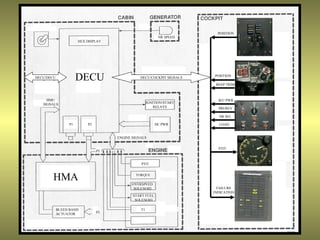
This document describes the components and operation of the FADEC (Full Authority Digital Engine Control) system used on the CH-47D Chinook helicopter.
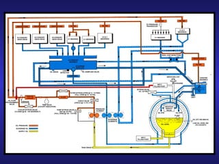
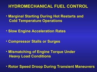
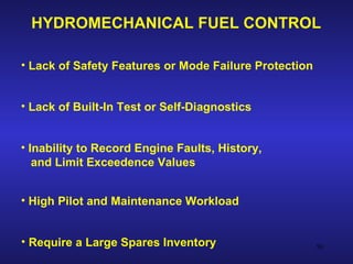
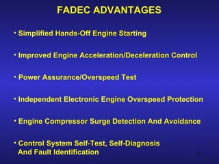
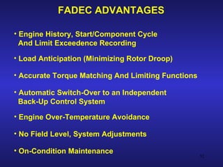
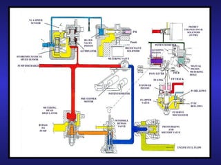
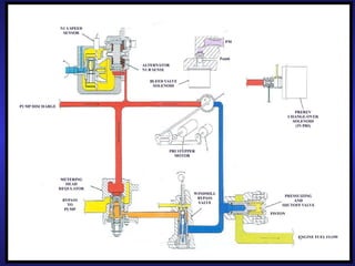
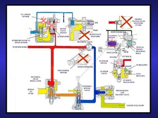
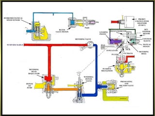
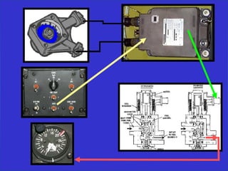
The FADEC system provides fully automated control of the engine to improve performance and safety compared to older hydromechanical fuel control systems. It controls engine starting, fuel flow, temperatures, speeds and more.
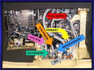
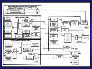
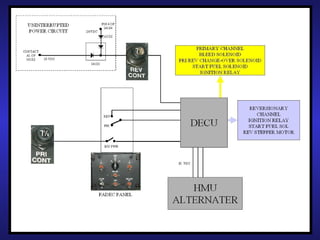
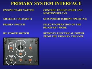
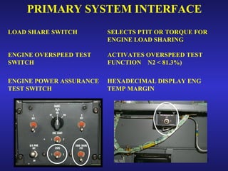
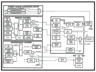
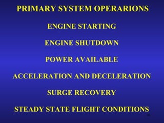
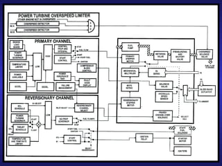
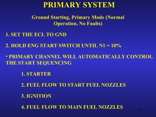
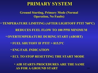
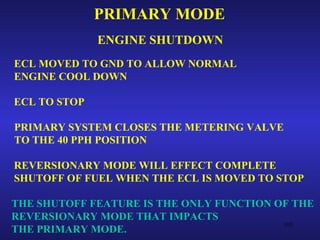
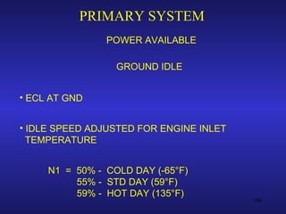
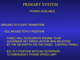
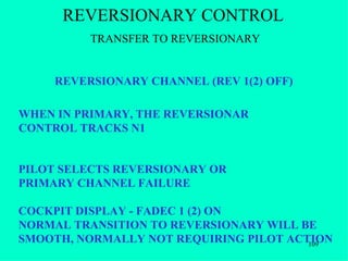
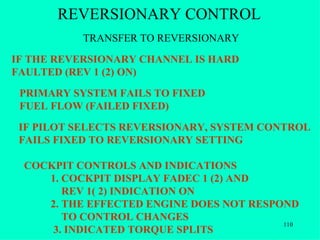
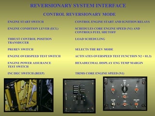
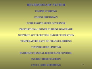
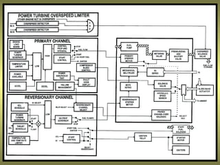
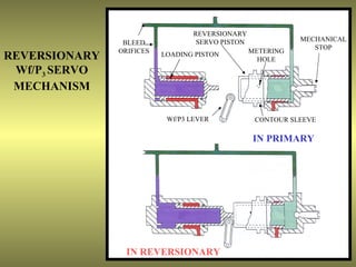
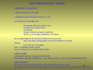
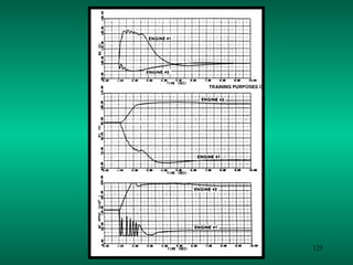
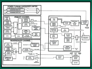
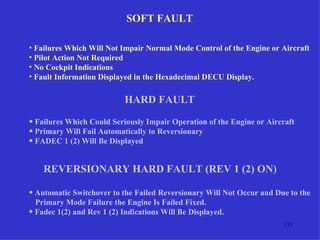
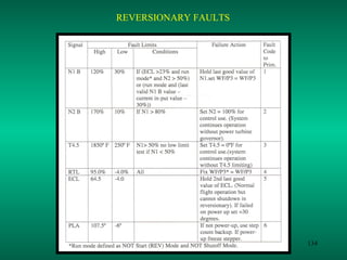
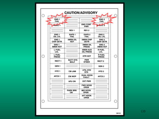
The system has primary and reversionary control modes. The primary mode operates normally while the reversionary mode acts as a backup if the primary fails. Both modes automatically control engine operation during starting, flight, and shutdown. The FADEC system improves engine operation during transients and faults can be detected and recorded.
1. Regulation structures like canal falls, cross regulators, distributary head regulators, canal escapes and outlets are constructed on canals to regulate water flow, level and velocity.
2. Canal falls are used to reduce water energy and control slopes, cross regulators maintain water supply and absorb fluctuations, and distributary head regulators control supply to off-taking canals.
3. The document provides details of regulation structures on the Kakrapar Left Bank Main Canal including head regulators, cross regulators, escapes and outlets to control water distribution across the canal network.
Dalton’s law of evaporation
The rate of evaporation depends upon the difference between the saturation vapour pressure in the air above
E= C(es-ea)
where c – coefficient depends upon barometric pressure
Es – saturation vapour pressure
Ea - Vapour pressure above 2 m height of water
Factors affecting
Temperature
Wind velocity
Atmospheric pressure
Nature of evaporating surface
Depth of water supply
Impurities in water
Energy budget method
LOW OF CONSERVATION of energy
Energy required is estimated by incoming outgoing, and stored energy in a specific time period
Total energy received from suns radiation = energy reflected + change in energy + energy required for evaporation
Energy budget method
most accurate method (evaporation is a function of the energy state of the water system)
difficult to evaluate all terms
energy balance equation has to be simplified
empirical formulas are used (although radiation measurements are preferable)
Water budget method
Characteristics:
Simple
Difficult to estimate Qd and Qs
Unreliable, accuracy will increase as Δt increases
Measurement et -
Direct measurement –
1 . Tank & lysimeter method
2. Field experimental method- no runoff no percolation
3. Soil moisture studies – gw deep
4. Integration method – laege area
5. Inflow and outflow studies
Infiltration rate
Infiltration capacity : The maximum rate at which, soil at a given time can absorb water.
f = fc when i ≥ fc
f = f 0when i < fc
where fc = infiltration capacity (cm/hr)
i = intensity of rainfall (cm/hr)
f = rate of infiltration (cm/hr)
Horton’s Formula:
This equation assumes an infinite water supply at the surface i.e., it assumes saturation conditions at the soil surface.
For measuring the infiltration capacity the following expression are used:
f(t) = fc + (f0 – fc) e–kt for
where k = decay constant ~ T-1
fc = final equilibrium infiltration capacity
f0 = initial infiltration capacity when t = 0
f(t) = infiltration capacity at any time t from start of the rainfall
td = duration of rainfall
Double Ring Infiltrometer
Infiltration indices The average value of infiltration is called infiltration index.
Two types of infiltration indices
φ – index (PHI INDEX)
w –index
PHI INDEX
- defined as average rate of rainfall such that excess volume of rainfall represents direct runoff
- unit is cm/hr or……
W INDEX
- average rate of loss (infiltration) averaged over whole storm period
- w index = P- Q- S
T
THUS phi index has to be some what than w index
IS 4987 - 1968
IN PLAINS – 520 km2
Elevation upto 1000 m – 260 to 390 km2
Hilly area – 130 km2
It is recommended that 10% of raingauge must be self recording type
This document classifies canals based on several factors:
- Permanency (temporary or permanent)
- Size (main canal, branch canal, major/minor distributaries, water courses) based on discharge rates
- Alignment (watershed, contour, side slope)
- Lining (lined or unlined)
- Purpose (irrigation, power, navigation, water supply, feeder, carrier, multipurpose)
- Financial returns (productive or protective)
It provides details on the definitions and characteristics of each classification.
Water resources and irrigation engineering pdfSaqib Imran
1. The document is a set of lecture notes on water resource and irrigation engineering written by Saqib Imran for civil engineering students and engineers.
2. It defines irrigation engineering and water resources engineering, and discusses the history of irrigation. It also covers types of canal lining, irrigation efficiency, factors affecting duty of water, and methods to improve duty of water.
3. The notes are intended to provide knowledge on various topics in irrigation and water resources engineering for students and engineers working in the field.
The irrigation system consists of several interconnected components that work together to transport water from its source to agricultural fields. The main intake structure or pumping station directs water into the irrigation system from sources like reservoirs or rivers. The conveyance system then transports water through canals to the distribution system of field ditches. These ditches carry water to individual fields for application using various field irrigation methods. The drainage system removes excess water from the fields. Canal structures like drops, turnouts, checks, and weirs are used to control water flow and distribution throughout the system.
1. Dams are constructed across rivers to store flowing water and come in various types like earth, rockfill, gravity, steel, timber and arch dams. The selection of dam type depends on site conditions like topography, geology and availability of construction materials.
2. Gravity dams derive their strength from their weight and weight of water pressure pushing them into the ground. They are made of concrete or masonry and work by balancing the water pressure on upstream side with weight and pressure on downstream side.
3. Factors considered in gravity dam design include water pressure, seismic forces, uplift pressure, weight of dam, and ensuring stability against sliding, overturning and cracking. Galleries are provided for drainage,
The document discusses the key components of a gravity dam and their functions. It describes drainage galleries, which provide access to the dam interior, and shafts, which provide vertical access. It explains that the overflow section contains the spillway to release surplus water. The non-overflow section is the rest of the dam, where a road may be located. It also describes the power house, energy dissipation works, outlets, and different types of joints in a gravity dam.
This document defines several key terms related to irrigation:
- Base period refers to the time from initial watering to final watering of a crop before harvest.
- Crop period is the time from planting to harvest.
- Duty is the area irrigated by a unit discharge over the base period and relates water volume to crop area.
- Delta is the total water depth required by a crop over its lifetime in the field.
- Gross command area is the total area bounded by drainage boundaries that can be irrigated by a canal system.
- Culturable command area is the area within the gross command area suitable for crop growth, excluding non-arable land.
050218 chapter 7 spillways and energy dissipatorsBinu Karki
The document discusses different types of spillways and energy dissipaters used in dams. It describes overflow or ogee spillways, chute spillways, and other spillway types. The main purposes of spillways are to safely release surplus water from the reservoir and regulate floods. Energy dissipaters, like stilling basins, are structures that reduce the high kinetic energy of water flowing from spillways to prevent erosion. Hydraulic jumps, baffle blocks, and deflector buckets are common dissipater types discussed in the document. Design considerations like discharge calculations, basin length, and tailwater conditions are also covered.
This document discusses different types of weirs based on their shape, crest width, size, discharge conditions, ratios, alignments, and special types. The most commonly used weir is the rectangular weir. The discharge relationship for weirs is generally expressed as Q=CL(2g/H)^(1/2) where Q is discharge, C is the discharge coefficient, L is the length of the weir, g is acceleration due to gravity, and H is the head over the weir crest. Some other weir types discussed include triangular, trapezoidal, Cipolletti, parabolic, circular, suppressed, contracted, free falling, submerged, proportional, labyrinth, piano key,
Minor Irrigation
1 Bandhara
Component Parts
Site selection, types of bandhara
2 Percolation Tank
Component Parts, Site selection
3 Lift Irrigation
4 Drip Irrigation
5 Sprinkler Irrigation
6 Farm Ponds
7 Well Irrigation
This document discusses reservoirs and dams. It covers why water is stored in reservoirs, such as to raise head for hydroelectric power and smooth flows for irrigation. It describes methods for determining reservoir size, dam design considerations like forces and types of dams, and technical issues like silting and failure modes. The social impacts of dams are also addressed, such as displacement of local populations and changes to downstream economies. Examples of good and bad dam projects are provided for analysis of who benefits from and makes decisions about dams.
1) Canals are artificial channels constructed to carry water from a source like a river or reservoir to agricultural fields.
2) Canals are classified based on their water source (permanent or inundation), function (irrigation, navigation, power), alignment (watershed, contour, side slope), discharge (main, branch, distributary), and whether they have lining.
3) The cross-section of a canal includes components like side slopes, berms, freeboard, banks, and may involve partial cutting and filling to achieve a balancing depth.
For More Visit - www.civilengineeringadda.com
Irrigation Efficiency
Water conveyance Efficiency
It takes into account, conveyance or transit losses such as seepage through canal and evaporation through it.
η_c=W_f/W_r ×100
Where, Wf = water delivered to the field
Wr = water delivered from river or stream
Water Application Efficiency
It is the ratio of water stored in root zone to the water delivered to the field.
η_a=W_s/W_f ×100
Where, WS = water weight stored in root zone
WS = Wf – deep percolation – runoff
Wf = water delivered to the field
This efficiency is also called as farm efficiency and it depends on the irrigation technique that has been adopted.
Water use efficiency
It is the ratio of water used beneficially or consumptively to the water delivered to the field.
η_u=W_u/W_f ×100
Where, Wf = water delivered to the field
WU = consumptively used water
Water Storage Efficiency
This is the ratio of actual water stored in the root zone to the water needed to be stored to bring the moisture content upto field capacity.
Water Distribution efficiency
This evaluate the degree to which water is uniformly distributed to the root zone throughout the field area.
η_d=(1-y/d)×100
Where, d = average depth
y = Average numerical deviation in the depth of water stored from the average depth stored during irrigation
Question – the depths of penetration along the length of a border strip at points 30 m apart were proved. There observed values are 2 m, 1.9 m, 1.8 m, 1.6 m and 1.5 m. Compute the water distribution efficiency.
Solution –
Water distribution efficiency,
η_d=(1-y/d)×100
Where, d = average depth
d = (2+1.9+1.8+1.6+1.5)/5=1.76
And y = average numerical deviation
y = 1/5((2-1.76)+(1.9-1.76)+(1.8-1.76)+(1.76-1.6)+(1.76-1.5)=0.168
Therefore,
η_d=(1-0.168/1.76)×100
η_d=90.45%
Consumptive Use Efficiency
It is the ratio of water used consumptively to the net amount of water from the root zone.
Regulation works are structures constructed to regulate water flow in canals. The main types are head regulators, cross regulators, canal escapes, and canal outlets. Head regulators control water entry into off-taking channels from parent channels. Cross regulators are located downstream of off-takes and help control water levels and closures for repairs. Canal outlets connect distribution channels to field channels and supply water to irrigation fields at regulated discharges.
A masonry dam is a gravity structure that relies on its self-weight for stability. There are two main forces acting on the dam: (1) water pressure from the reservoir pushing down, and (2) the self-weight of the dam material. The resultant force of these two must fall within the dam for stability. Key stability criteria include: compressive stresses must not exceed permissible limits, tensile stresses must be avoided, sliding and overturning moments must be resisted with sufficient factors of safety. Proper design and analysis of masonry dams is necessary to ensure stability under the acting water and self-weight forces.
Dams are constructed across rivers to create reservoirs for various purposes like irrigation, hydropower, flood control, and water supply. They are built in narrow valleys with good foundation. Dams can be classified based on their function, hydraulic design, materials of construction, rigidity, and structural action. Common types include gravity dams, embankment dams, arch dams, and buttress dams. Spillways provide controlled release of water from reservoirs to prevent overtopping of dams.
This document discusses balancing depth in canal design, canal lining, and design principles for lined canals. It defines balancing depth as the depth where the amount of cut material equals the amount of fill material. It lists advantages of canal lining such as reducing seepage losses and maintenance costs. Design principles for lined canals include selecting economical cross-sectional shapes based on discharge and using side slopes of 1:1 or 1.25:1 that are stable for the soil. Input data includes discharge, roughness, slopes, and maximum velocity, and output data includes breadth and depth calculated using Manning's equation.
This document discusses the design of penstock pipes, which carry water from forebay tanks to power houses and must withstand high water pressures. It describes the types of penstocks as buried or exposed, and their components like anchor blocks and valves. It explains how to size penstocks by calculating the optimal diameter that minimizes costs and head losses. Factors that contribute to head losses like friction and turbulence are also outlined. The document provides the method to calculate penstock wall thickness and notes air vents are included to release air during filling and draining of the pipes. In conclusion, it thanks the reader and lists references used.
Introduction to irrigation engineering 19 07 1 (1)holegajendra
This document provides information about the Water Resource Engineering course taught by Mr. Hole G.R. at J.S. Polytechnic in Pune, India. The course is divided into 6 units covering topics like introduction to irrigation and hydrology, water requirements of crops, dams and spillways, minor and micro irrigation, diversion head works, and canals. The course outcomes include estimating hydrological parameters, crop water requirements, designing dam and spillway components, executing minor irrigation schemes, and designing and maintaining canals. The first unit covers definitions of irrigation, necessity of irrigation in India, advantages and disadvantages of irrigation, classification of irrigation, and hydrological concepts. Different types of irrigation like surface, subsurface, flow, and
Human powered and animal powered devices are commonly used to lift water for irrigation in small fields. Common human powered devices include swing baskets, counterpoise lifts, and dons which can lift water from depths up to a few meters. Animal powered devices include rope-and-bucket lifts, self-emptying buckets, and Persian wheels which can lift water from depths up to 30 meters using bullocks. Mechanically powered pumps such as reciprocating pumps, centrifugal pumps, and self-priming centrifugal pumps are used to lift larger volumes of water to higher heads for irrigating horticultural crops. These pumps are powered by engines or electric motors.
This document discusses Ghanewadi, a lake located 8 km north of Jalna City in India that serves as the primary water source for the city. [1] It was constructed in the early 1930s to supply drinking water to Jalna. [2] However, over decades of neglect, silt accumulation reduced the lake's storage capacity such that water supply declined to once a month. [3] In 2010, a non-profit group began removing silt to reclaim storage capacity and improve water supply, removing over 45,000 tractor-loads in the first year through community donations. [4] Continued silt removal efforts aim to fully restore the lake's original 1.44 billion liter capacity to reliably
Using excess air to make lean mixture forcefully put down engine cylinder at above 50 km/h speed. an axial fan is used for suction air from atmosphere. by this experiment brake thermal efficiency 2% increase and fuel efficiency also increase 5 km/h compare to ordinary operation.
Loadster Load Testing by RapidValue SolutionsRapidValue
This document explains about Loadster Load testing and provides the details about the steps that are required to perform the load test. This document is prepared after the successful implementation of the Load Test in one of our customer projects. The blog, essentially, gives you an idea of how Load Testing is considered to be a method to determine how an application will behave under load. “Load”, generally, refers to the total user traffic at a given time. This document also explains how Load testing software can be used to gain knowledge about several different metrics like stress, stability, spike, scalability, baseline.
Loadster workbench is an integrated environment which enables you to perform load testing. Load test can be performed using any number of virtual users. It gives us provision to record and edit the scripts and the test results are obtained after performing the test. It has an in-built load engine through which we can perform load testing with concurrent virtual users.
Project Repository
Loadster has a repository called project repository for each project, script etc. Test results, after completing the load test, is also stored in this repository.
Dashboard
When the load test starts providing information, regarding the number of users, time taken to complete the test is displayed on the dashboard. In spite of that, there are number of options provided on the left side of dashboard namely response times, network throughput, transaction throughput, transaction, error, virtual user, and load engine information. You can view a graph of load test by clicking on any of these options as the load test runs.
IC ENGINE TESTING
At a design and development stage an engineer would design an engine with certain aims in his mind. The aims may include the variables like indicated power, brake power,
brake specific fuel consumption, exhaust emissions, cooling of engine, maintenance free operation etc. The other task of the development engineer is to reduce the cost and
improve power output and reliability of an engine. In trying to achieve these goals he has
to try various design concepts. After the design the parts of the engine are manufactured for the dimensions and surface finish and may be with certain tolerances. In order verify the designed and developed engine one has to go for testing and performance evaluation of the engines.
Thus, in general, a development engineer will have to conduct a wide variety of engine
tests starting from simple fuel and air-flow measurements to taking of complicated
injector needle lift diagrams, swirl patterns and photographs of the burning process in
the combustion chamber. The nature and the type of the tests to be conducted depend
upon various factors, some of which are: the degree of development of the particular
design, the accuracy required, the funds available, the nature of the manufacturing
company, and its design strategy. In this chapter, only certain basic tests and
measurements will be considered.
After studying this unit, you should be able to
• understand the performance parameters in evaluation of IC engine
performance,
• calculate the speed of IC engine, fuel consumption, air consumption, etc.,
• evaluate the exhaust smoke and exhaust emission, and
• differentiate between the performance of SI engine and CI engines.
The document provides information on diesel engine operation and diagnosis. It explains that diesel engines work via compression ignition where fuel is injected into hot compressed air, igniting the fuel. It describes the differences between direct injection and indirect injection diesel engines. It also outlines the key components of diesel engines like the fuel system, injection pump, injectors, turbochargers, and emission control systems. Advantages include torque and fuel economy, while disadvantages include noise, smell and cold starting issues.
This document summarizes the testing and performance of diesel and petrol engines. It describes the key components and operating principles of diesel and petrol engines. It then discusses various performance characteristics of internal combustion engines that are used to evaluate engine performance, such as brake thermal efficiency, indicated thermal efficiency, specific fuel consumption, mechanical efficiency, volumetric efficiency, air fuel ratio, and mean effective pressure. The performance of engines is tested by measuring fuel consumption, brake power, and specific power output using various types of dynamometers.
This document describes a six-stroke engine designed by Malcolm Beare that combines aspects of two-stroke and four-stroke engines. It works by using a piston in the cylinder head that intakes and exhausts like a two-stroke while the bottom remains a conventional four-stroke. This hybrid design increases torque by 35% and efficiency, while reducing weight and parts compared to a four-stroke. It provides thermodynamic advantages such as greater expansion and slower piston acceleration. The six-stroke engine could replace conventional heads on existing engines.
this is the ppt on 2 stroke and 4 stroke petrol engine. . i made this ppt with the help of dhrumil patel .who is in the L.D. college of engineering in chemical department. . i am very thankful to him for being my great partner. . .thanx dhrumil..
The document discusses the history and workings of different types of engines. It describes how Nicolaus Otto invented the four-stroke engine in 1876. A four-stroke engine completes one cycle over four strokes and two revolutions of the crankshaft. It also describes how a two-stroke engine, invented in 1878 by Clerk, completes a cycle in one revolution due to the use of ports instead of valves.
This document is a task training program for a Cessna 152 aircraft. It lists 90 maintenance tasks that a trainee will need to complete, such as preflight inspections, refueling the aircraft, replacing components like wheels and spark plugs, and performing scheduled inspections like 50-hour and 100-hour checks. Each task is recorded with details like the task description, whether it was an observation or practical experience, the reference material, and signatures to verify completion. The program is intended to train maintenance technicians on all aspects of servicing and repairing a Cessna 152.
The document provides specifications for a 22500 KVA, 3 phase, 4 pole turbine generator including operating parameters such as voltage, current, speed, power factor, ratings, excitation voltage and current. It also lists turbine alarms and trip parameters related to lubrication oil pressure and temperature, bearing temperatures, vibrations, axial displacement and electrical faults. Key operating parameters outlined include load, steam pressures and temperatures, flows, lubricating oil pressures and temperatures.
The document describes the fuel injection system used in Caterpillar 3408E/3412E engines. It contains diagrams and descriptions of the key components of the Hydraulic Electronic Unit Injection (HEUI) system, including the fuel pump, oil cooler, sensors, injectors, and Electronic Control Module (ECM). It also provides details on the synchronization calibration process, injection waveform characteristics, and operating modes like cold start and derate functions.
1969 Johnson Evinrude Outboard 50hp-125hp Service Repair Manual.pdf7jfksmeidjdm
This document provides a table of contents for an owner's manual covering safety, maintenance, troubleshooting, and repair procedures for boat engines. The document outlines chapters on topics like the powerhead, fuel system, ignition, electrical systems, lower unit, and accessories. It includes sections on maintenance, tune-ups, winterization, and specifications for different engine models from the 1950s through the 1970s.
1958 Johnson Evinrude Outboard 50hp-125hp Service Repair Manual.pdf8fusjkkmdd3e
This document provides a table of contents for an owner's manual covering safety, maintenance, troubleshooting, and repair procedures for boat engines. The table of contents lists 13 chapters that cover topics like the powerhead, fuel system, ignition, electrical systems, lower unit, and hand starter. It also includes appendices with wiring diagrams and specifications for various engine models from 1958 to 1972.
1967 Johnson Evinrude Outboard 50hp-125hp Service Repair Manual.pdffjskekmdmdme
This document provides a table of contents for an owner's manual covering safety, maintenance, troubleshooting, and repair procedures for boat engines. The document outlines chapters on topics like the powerhead, fuel system, ignition, electrical systems, lower unit, and accessories. It includes sections on maintenance, tune-ups, winterization, and specifications for different engine models from 1958 to 1972.
1959 Johnson Evinrude Outboard 50hp-125hp Service Repair Manual.pdf7jfksmeidjdm
This document is a table of contents for a boating repair manual. It lists 13 chapters that cover topics like safety, engine tuning, the powerhead, fuel systems, ignition, electrical systems, accessories, the lower unit, hand starting, and maintenance. The chapters are broken down into sections that provide descriptions, troubleshooting, removal/disassembly, cleaning/inspection, and installation instructions for various boat engine components.
1962 Johnson Evinrude Outboard 50hp-125hp Service Repair Manual.pdf7jfksmeidjdm
This document provides a table of contents for an owner's manual covering safety, maintenance, troubleshooting, and repair procedures for boat engines. The document outlines chapters on topics like the powerhead, fuel system, ignition, electrical systems, lower unit, and accessories. It includes sections on maintenance, tune-ups, winterization, and specifications for different engine models from 1958 to 1972.
Strategies for Effective Upskilling is a presentation by Chinwendu Peace in a Your Skill Boost Masterclass organisation by the Excellence Foundation for South Sudan on 08th and 09th June 2024 from 1 PM to 3 PM on each day.
हिंदी वर्णमाला पीपीटी, hindi alphabet PPT presentation, hindi varnamala PPT, Hindi Varnamala pdf, हिंदी स्वर, हिंदी व्यंजन, sikhiye hindi varnmala, dr. mulla adam ali, hindi language and literature, hindi alphabet with drawing, hindi alphabet pdf, hindi varnamala for childrens, hindi language, hindi varnamala practice for kids, https://www.drmullaadamali.com
বাংলাদেশের অর্থনৈতিক সমীক্ষা ২০২৪ [Bangladesh Economic Review 2024 Bangla.pdf] কম্পিউটার , ট্যাব ও স্মার্ট ফোন ভার্সন সহ সম্পূর্ণ বাংলা ই-বুক বা pdf বই " সুচিপত্র ...বুকমার্ক মেনু 🔖 ও হাইপার লিংক মেনু 📝👆 যুক্ত ..
আমাদের সবার জন্য খুব খুব গুরুত্বপূর্ণ একটি বই ..বিসিএস, ব্যাংক, ইউনিভার্সিটি ভর্তি ও যে কোন প্রতিযোগিতা মূলক পরীক্ষার জন্য এর খুব ইম্পরট্যান্ট একটি বিষয় ...তাছাড়া বাংলাদেশের সাম্প্রতিক যে কোন ডাটা বা তথ্য এই বইতে পাবেন ...
তাই একজন নাগরিক হিসাবে এই তথ্য গুলো আপনার জানা প্রয়োজন ...।
বিসিএস ও ব্যাংক এর লিখিত পরীক্ষা ...+এছাড়া মাধ্যমিক ও উচ্চমাধ্যমিকের স্টুডেন্টদের জন্য অনেক কাজে আসবে ...
How to Make a Field Mandatory in Odoo 17Celine George
In Odoo, making a field required can be done through both Python code and XML views. When you set the required attribute to True in Python code, it makes the field required across all views where it's used. Conversely, when you set the required attribute in XML views, it makes the field required only in the context of that particular view.
Chapter wise All Notes of First year Basic Civil Engineering.pptxDenish Jangid
Chapter wise All Notes of First year Basic Civil Engineering
Syllabus
Chapter-1
Introduction to objective, scope and outcome the subject
Chapter 2
Introduction: Scope and Specialization of Civil Engineering, Role of civil Engineer in Society, Impact of infrastructural development on economy of country.
Chapter 3
Surveying: Object Principles & Types of Surveying; Site Plans, Plans & Maps; Scales & Unit of different Measurements.
Linear Measurements: Instruments used. Linear Measurement by Tape, Ranging out Survey Lines and overcoming Obstructions; Measurements on sloping ground; Tape corrections, conventional symbols. Angular Measurements: Instruments used; Introduction to Compass Surveying, Bearings and Longitude & Latitude of a Line, Introduction to total station.
Levelling: Instrument used Object of levelling, Methods of levelling in brief, and Contour maps.
Chapter 4
Buildings: Selection of site for Buildings, Layout of Building Plan, Types of buildings, Plinth area, carpet area, floor space index, Introduction to building byelaws, concept of sun light & ventilation. Components of Buildings & their functions, Basic concept of R.C.C., Introduction to types of foundation
Chapter 5
Transportation: Introduction to Transportation Engineering; Traffic and Road Safety: Types and Characteristics of Various Modes of Transportation; Various Road Traffic Signs, Causes of Accidents and Road Safety Measures.
Chapter 6
Environmental Engineering: Environmental Pollution, Environmental Acts and Regulations, Functional Concepts of Ecology, Basics of Species, Biodiversity, Ecosystem, Hydrological Cycle; Chemical Cycles: Carbon, Nitrogen & Phosphorus; Energy Flow in Ecosystems.
Water Pollution: Water Quality standards, Introduction to Treatment & Disposal of Waste Water. Reuse and Saving of Water, Rain Water Harvesting. Solid Waste Management: Classification of Solid Waste, Collection, Transportation and Disposal of Solid. Recycling of Solid Waste: Energy Recovery, Sanitary Landfill, On-Site Sanitation. Air & Noise Pollution: Primary and Secondary air pollutants, Harmful effects of Air Pollution, Control of Air Pollution. . Noise Pollution Harmful Effects of noise pollution, control of noise pollution, Global warming & Climate Change, Ozone depletion, Greenhouse effect
Text Books:
1. Palancharmy, Basic Civil Engineering, McGraw Hill publishers.
2. Satheesh Gopi, Basic Civil Engineering, Pearson Publishers.
3. Ketki Rangwala Dalal, Essentials of Civil Engineering, Charotar Publishing House.
4. BCP, Surveying volume 1
Walmart Business+ and Spark Good for Nonprofits.pdfTechSoup
"Learn about all the ways Walmart supports nonprofit organizations.
You will hear from Liz Willett, the Head of Nonprofits, and hear about what Walmart is doing to help nonprofits, including Walmart Business and Spark Good. Walmart Business+ is a new offer for nonprofits that offers discounts and also streamlines nonprofits order and expense tracking, saving time and money.
The webinar may also give some examples on how nonprofits can best leverage Walmart Business+.
The event will cover the following::
Walmart Business + (https://business.walmart.com/plus) is a new shopping experience for nonprofits, schools, and local business customers that connects an exclusive online shopping experience to stores. Benefits include free delivery and shipping, a 'Spend Analytics” feature, special discounts, deals and tax-exempt shopping.
Special TechSoup offer for a free 180 days membership, and up to $150 in discounts on eligible orders.
Spark Good (walmart.com/sparkgood) is a charitable platform that enables nonprofits to receive donations directly from customers and associates.
Answers about how you can do more with Walmart!"
49. HYDROMECHANICAL FUEL CONTROL
• Marginal Starting During Hot Restarts and
Cold Temperature Operations
• Slow Engine Acceleration Rates
• Compressor Stalls or Surges
• Mismatching of Engine Torque Under
Heavy Load Conditions
• Rotor Speed Droop During Transient Maneuvers
49
50. HYDROMECHANICAL FUEL CONTROL
• Lack of Safety Features or Mode Failure Protection
• Lack of Built-In Test or Self-Diagnostics
• Inability to Record Engine Faults, History,
and Limit Exceedence Values
• High Pilot and Maintenance Workload
• Require a Large Spares Inventory 50
51. FADEC ADVANTAGES
• Simplified Hands-Off Engine Starting
• Improved Engine Acceleration/Deceleration Control
• Power Assurance/Overspeed Test
• Independent Electronic Engine Overspeed Protection
• Engine Compressor Surge Detection And Avoidance
• Control System Self-Test, Self-Diagnosis
And Fault Identification 51
52. FADEC ADVANTAGES
• Engine History, Start/Component Cycle
And Limit Exceedence Recording
• Load Anticipation (Minimizing Rotor Droop)
• Accurate Torque Matching And Limiting Functions
• Automatic Switch-Over to an Independent
Back-Up Control System
• Engine Over-Temperature Avoidance
• No Field Level, System Adjustments
• On-Condition Maintenance
52
53. PRIMARY MODE FUNCTIONS
• Twin Engine Load
Sharing
• Electronic Power Turbine Speed
Governing
• Transient Load Anticipation Using Rotor Speed
And Thrust Rate
• Transient Torque Smoothing Using Power
Turbine Rates 53
54. PRIMARY MODE FUNCTIONS
• Contingency Power To Meet Aircraft
Demands
• Automatic Engine Starting, Sequencing
Ignition, Start Fuel, And Stabilized Engine
Operation At Idle
• Acceleration And Deceleration Using
Closed Loop NDOT* Control
• Engine Temperature And
Temperature Rate Limiting 54
55. PRIMARY MODE FUNCTIONS
• Compressor Bleed Valve Control (For
Both Transient And Steady State Surge
Margin)
• Surge Detection/Surge
Recovery
• Fuel Flow Limiting
• Engine Fail Detection
55
56. PRIMARY MODE FUNCTIONS
• Engine Power Assurance Test
• Engine History/Fault Recording
• Automatic Switch Over To The
Reversionary Channel In The Event Of
Primary Channel Hard Fault
• Data Bus For Decu To Decu Cross
Communication 56
57. REVERSIONARY MODE FUNCTIONS
• Automatic Start Sequencing Including
Over Temperature Protection
• Pilot Controlled Start Fuel Enrichment/De-Enrichment,
If Required Through ECL Modulation
• Proportional Power Turbine Governing And Automatic
Power Modulation Response To Thrust Rate Changes
• Engine 1 (2) Increase/Decrease Switch To Input Power
Turbine Changes For Accurate Load Matching Of The
Engines 57
58. REVERSIONARY MODE FUNCTIONS
• Full Contingency Power Capability
• Over Temperature Protection Throughout The Engine
Operational Range
• Engine Shutdown In Response To The ECL
• Tracking Of The Primary Channels Operation Allowing A
Smooth Switch- Over When The Reversionary Channel Is
Selected, Or The Primary Channel Fails 58
91. PRIMARY SYSTEM INTERFACE
ENGINE START SWITCH CONTROL ENGINE START AND
IGNITION RELAYS
NR SELECTOR (N2SET) SETS POWER TURBINE SPEED (N2)
PRI/REV SWITCH SELECTS OPERATION OF THE
PRI OR REV MODE
B/U POWER SWITCH REMOVES ELECTRICAL POWER
FROM THE PRIMARY CHANNEL
91
92. PRIMARY SYSTEM INTERFACE
LOAD SHARE SWITCH SELECTS PTIT OR TORQUE FOR
ENGINE LOAD SHARING
ENGINE OVERSPEED TEST ACTIVATES OVERSPEED TEST
SWITCH FUNCTION N2 < 81.3%)
ENGINE POWER ASSURANCE HEXADECIMAL DISPLAY ENG
TEST SWITCH TEMP MARGIN
92
93. PRIMARY SYSTEM INTERFACE
ENGINE CONDITION SCHEDULES CORE ENGINE SPEED (N1)
LEVER (ECL) AND CONTROLS FUEL SHUTOFF
THRUST CONTROL LOAD ANTICIPATION
POSITION TRANSDUCER
93
94. POSITION
NR SPEED
HEX DISPLAY
DECU/DECU DECU DECU/COCKPIT SIGNALS
POSITION
BEEP TRIM
HMU B/U PWR
SIGNALS IGNITION/START
RELAYS PRI/REV
NR SEL
P1 P3 DC PWR LOAD
ENGINE SIGNALS
PTIT
P3
PTIT
HMA TORQUE
OVERSPEED
SOLENOID FAILURE
INDICATION
START FUEL
SOLENOID
BLEED BAND T1
ACTUATOR P3
94
96. PRIMARY SYSTEM OPERARIONS
ENGINE STARTING
ENGINE SHUTDOWN
POWER AVAILABLE
ACCELERATION AND DECELERATION
SURGE RECOVERY
STEADY STATE FLIGHT CONDITIONS
96
97. PRIMARY SYSTEM OPERARIONS
TRANSIENT FLIGHT CONDITIONS
TEMPERATURE LIMITING
POWER TURBINE OVERSPEED LIMITING
POWER ASSURANCE TEST
FAULT CODE RECORDING
ENGINE HISTORY RECORDING 97
103. PRIMARY SYSTEM
Ground Starting, Primary Mode (Normal
Operation, No Faults)
1. SET THE ECL TO GND
2. HOLD ENG START SWITCH UNTIL N1 = 10%
• PRIMARY CHANNEL WILL AUTOMATICALLY CONTROL
THE START SEQUENCING
1. STARTER
2. FUEL FLOW TO START FUEL NOZZLES
3. IGNITION
4. FUEL FLOW TO MAIN FUEL NOZZLES 103
104. PRIMARY SYSTEM
Ground Starting, Primary Mode (Normal
Operation, No Faults)
• TEMPERATURE LIMITING (AFTER LIGHTOFF PTIT 760°C)
REDUCES FUEL FLOW TO 100 PPH MINIMUM
• OVERTEMPERATURE DURING START (ABORT)
• FUEL SHUTOFF IF PTIT > 815.5ºC
• ENG FAIL INDICATION
• ECL TO STOP RESETTING THE START MODE
• AIR STARTS PROCEDURES ARE THE SAME
AS FOR A GROUND START 104
105. PRIMARY MODE
ENGINE SHUTDOWN
ECL MOVED TO GND TO ALLOW NORMAL
ENGINE COOL DOWN
ECL TO STOP
PRIMARY SYSTEM CLOSES THE METERING VALVE
TO THE 40 PPH POSITION
REVERSIONARY MODE WILL EFFECT COMPLETE
SHUTOFF OF FUEL WHEN THE ECL IS MOVED TO STOP
THE SHUTOFF FEATURE IS THE ONLY FUNCTION OF THE
REVERSIONARY MODE THAT IMPACTS
105
THE PRIMARY MODE.
106. PRIMARY SYSTEM
POWER AVAILABLE
GROUND IDLE
• ECL AT GND
• IDLE SPEED ADJUSTED FOR ENGINE INLET
TEMPERATURE
N1 = 50% - COLD DAY (-65°F)
55% - STD DAY (59°F)
59% - HOT DAY (135°F)
106
107. PRIMARY SYSTEM
POWER AVAILABLE
GROUND TO FLIGHT TRANSITION
• ECL MOVED TO FLT POSITION
FADEC WILL ACCELERATE ENGINE TO NP
GOVERNOR SET SPEED (ROTOR RPM SELECTED
BY THE NR SWITCH ON THE FADEC CONTROL PANEL)
ECL FLT POSITION SETS NG GOVERNOR
TO EMERGENCY POWER SPEED LIMIT 107
109. REVERSIONARY CONTROL
TRANSFER TO REVERSIONARY
REVERSIONARY CHANNEL (REV 1(2) OFF)
WHEN IN PRIMARY, THE REVERSIONAR
CONTROL TRACKS N1
PILOT SELECTS REVERSIONARY OR
PRIMARY CHANNEL FAILURE
COCKPIT DISPLAY - FADEC 1 (2) ON
NORMAL TRANSITION TO REVERSIONARY WILL BE
SMOOTH, NORMALLY NOT REQUIRING PILOT ACTION
109
110. REVERSIONARY CONTROL
TRANSFER TO REVERSIONARY
IF THE REVERSIONARY CHANNEL IS HARD
FAULTED (REV 1 (2) ON)
PRIMARY SYSTEM FAILS TO FIXED
FUEL FLOW (FAILED FIXED)
IF PILOT SELECTS REVERSIONARY, SYSTEM CONTROL
FAILS FIXED TO REVERSIONARY SETTING
COCKPIT CONTROLS AND INDICATIONS
1. COCKPIT DISPLAY FADEC 1 (2) AND
REV 1( 2) INDICATION ON
2. THE EFFECTED ENGINE DOES NOT RESPOND
TO CONTROL CHANGES
110
3. INDICATED TORQUE SPLITS
112. REVERSIONARY SYSTEM INTERFACE
CONTROL REVERSIONARY MODE
ENGINE START SWITCH CONTROL ENGINE START AND IGNITION RELAYS
ENGINE CONDITION LEVER (ECL) SCHEDULES CORE ENGINE SPEED (N1) AND
CONTROLS FUEL SHUTOFF
THRUST CONTROL POSITION LOAD SCHEDULING
TRANSDUCER
PRI/REV SWITCH SELECTS THE REV MODE
ENGINE OVERSPEED TEST SWITCH ACTIVATES OVERSPEED TEST FUNCTION N2 < 81.3)
ENGINE POWER ASSURANCE HEXADECIMAL DISPLAY ENG TEMP MARGIN
TEST SWITCH
INC/DEC SWITCH (BEEP) TRIMS CORE ENGINE SPEED (N1)
112
113. POSITION
NR SPEED
HEX DISPLAY
DECU/DECU DECU DECU/COCKPIT SIGNALS
POSITION
BEEP TRIM
HMU B/U PWR
SIGNALS IGNITION/START
RELAYS PRI/REV
NR SEL
P1 P3 DC PWR LOAD
ENGINE SIGNALS
PTIT
P3
PTIT
HMA TORQUE
OVERSPEED
SOLENOID FAILURE
INDICATION
START FUEL
SOLENOID
BLEED BAND T1
ACTUATOR P3
113
114. REVERSIONARY SYSTEM
ENGINE STARTING
ENGINE SHUTDOWN
CORE ENGINE SPEED GOVERNOR
PROPORTIONAL POWER TURBINE GOVERNOR
WF/P3DOT ACCELERATION AND DECELERATION
TEMPERATURE RATE OF CHANGE LIMITING
TEMPERATURE LIMITING
HYDROMECHANICAL BLEED BAND CONTROL
INC/DEC TRIM FUNCTION
FAULT CODE REPORTING 114
122. REVERSIONARY MODE
GROUND STARTING
1. PILOT SETS ECL TO GND
2. HOLDS START SWITCH UNTIL N1 > 8%
AUTOMATIC CONTROL OF:
STARTER MOTOR (ABOVE 8%)
START FUEL SOLENOID
IGNITERS
START FLOW TO MAIN NOZZLES
Wf/P3 vs. N1 START SCHEDULE TO IDLE
ECL ENRICHMENT IF ENGINE TENDS TO STAGNATE
HAS NOT BEEN REQUIRED IN DEVELOPMENT ENGINE
TESTS
(-65º TO 135º F STARTS)
760º C TEMPERATURE LIMIT
FUEL CUTBACK TO 130 PPH MIN FLOW
AIR START
SAME PROCEDURE AS GROUND STARTS
WINDMILL SPEEDS WHERE N1 > 10% WILL START AS ECL IS MOVED FROM STOP
SHUTDOWN
ECL SET TO GND FOR ENGINE COOL DOWN ECL SET TO STOP 122
REVERSIONARY WILL IMMEDIATELY OPEN WINDMILL BYPASS FOR FUEL SHUTOFF
127. PAT
Power Assurance Test
Ref. Pg 8-9 0f the TM 55-1529-240-10
Perform First Flight of the Day
May be deferred to the Hover Check
a. NR Switch = 100%
b. ENG 1 ECL - Adjust
c. Thrust Control Lever - Raise until TRQ reads 60 to 80%. Stabilize for 30 seconds
d. Test switch ENG 2 - PWR ASSURANCE.
Check DECU display compare displayed value with PAT Trigger Value.
e. ENG 1 ECL - FLT
f. Repeat check with ENG 2 COND lever
g. THRUST CONT lever - Adjust
4. RRPM - Set as required
127
128. PAT
Power Assurance Test
Ref. Pg 2-55 0f the TM 55-1529-240-MTF
Perform First Flight of the Day
a. NR Switch = 100%
b. ENG 1 ECL - Adjust
c. Thrust Control Lever - Raise until TRQ reads 60 to 80%. Stabilize for 30 seconds
d. Test switch ENG 2 - PWR ASSURANCE.
Check DECU display (FE) An A means that the engine is operating at a
cooler temperature than a baseline spec engine. An F means that the
engine is operating at a warmer temperature than a baseline spec engine. .
Record Results.
d. THRUST CONT lever - Adjust
d. ENG 1 ECL - FLT
e. Repeat check with ENG 2 ENG COND lever
128
129. PAC
Power Assurance Check
Ref. Pg 2-76.1 0f the TM 55-1529-240-MTF
Ref. Section IV
Power Assurance Check Maximum Power Chart
Power Assurance Check Maximum Continuous Power Chart
Power Assurance Check engine Temperature Limits Chart
Power Assurance Check N1 Gas Generator Speed
Power Assurance Check Altitude Bands Chart
129
131. SOFT FAULT
• Failures Which Will Not Impair Normal Mode Control of the Engine or Aircraft
• Pilot Action Not Required
• No Cockpit Indications
• Fault Information Displayed in the Hexadecimal DECU Display.
HARD FAULT
• Failures Which Could Seriously Impair Operation of the Engine or Aircraft
• Primary Will Fail Automatically to Reversionary
• FADEC 1 (2) Will Be Displayed
REVERSIONARY HARD FAULT (REV 1 (2) ON)
• Automatic Switchover to the Failed Reversionary Will Not Occur and Due to the
Primary Mode Failure the Engine Is Failed Fixed.
• Fadec 1(2) and Rev 1 (2) Indications Will Be Displayed.
131