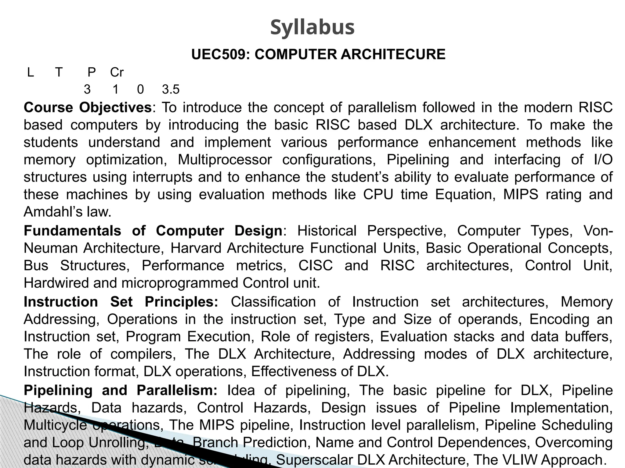
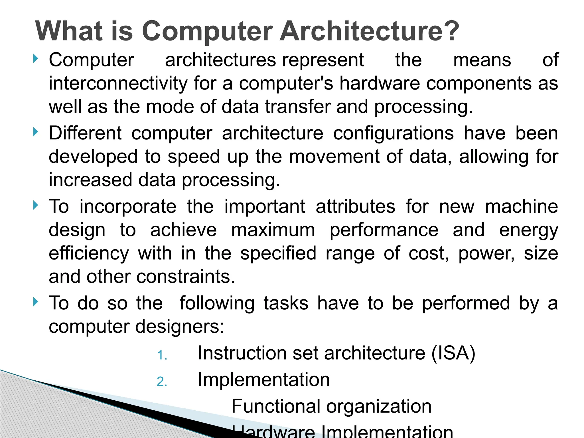
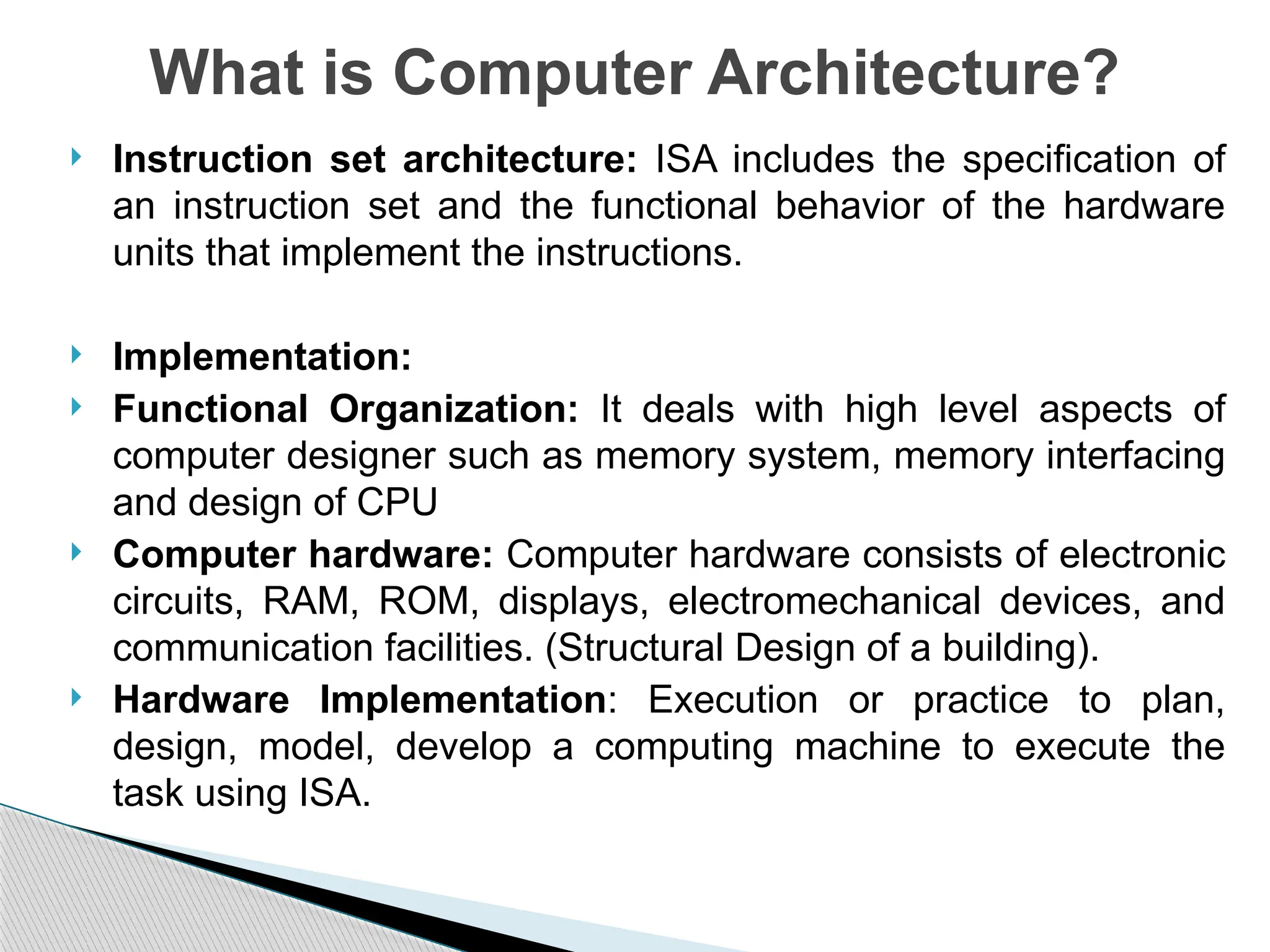
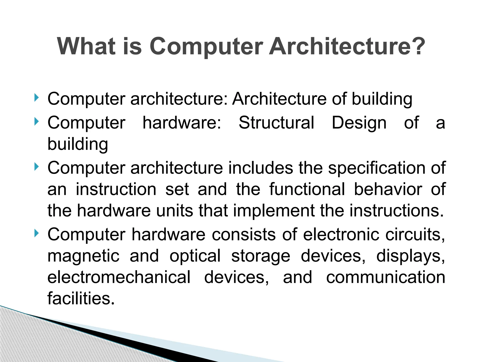
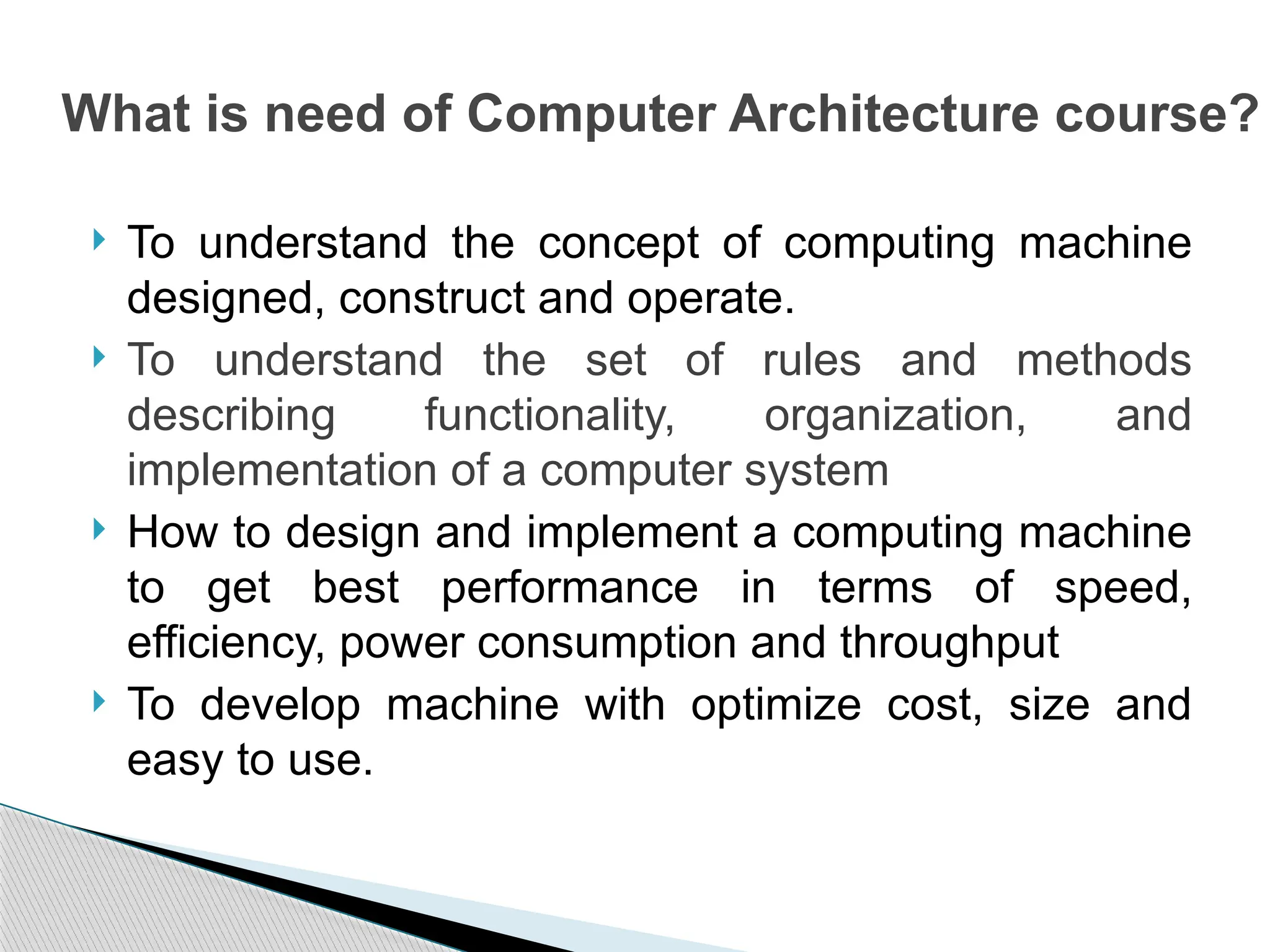
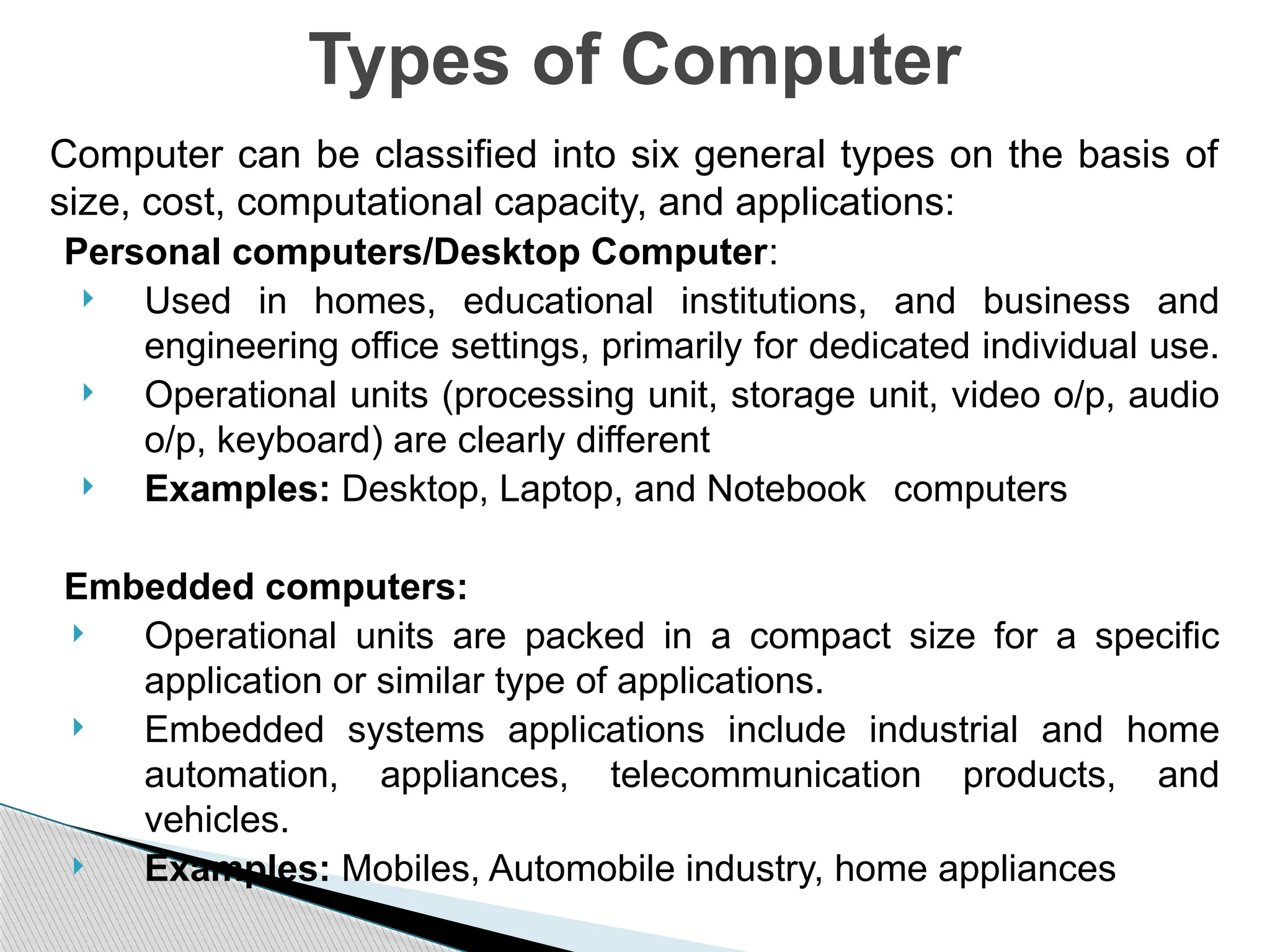
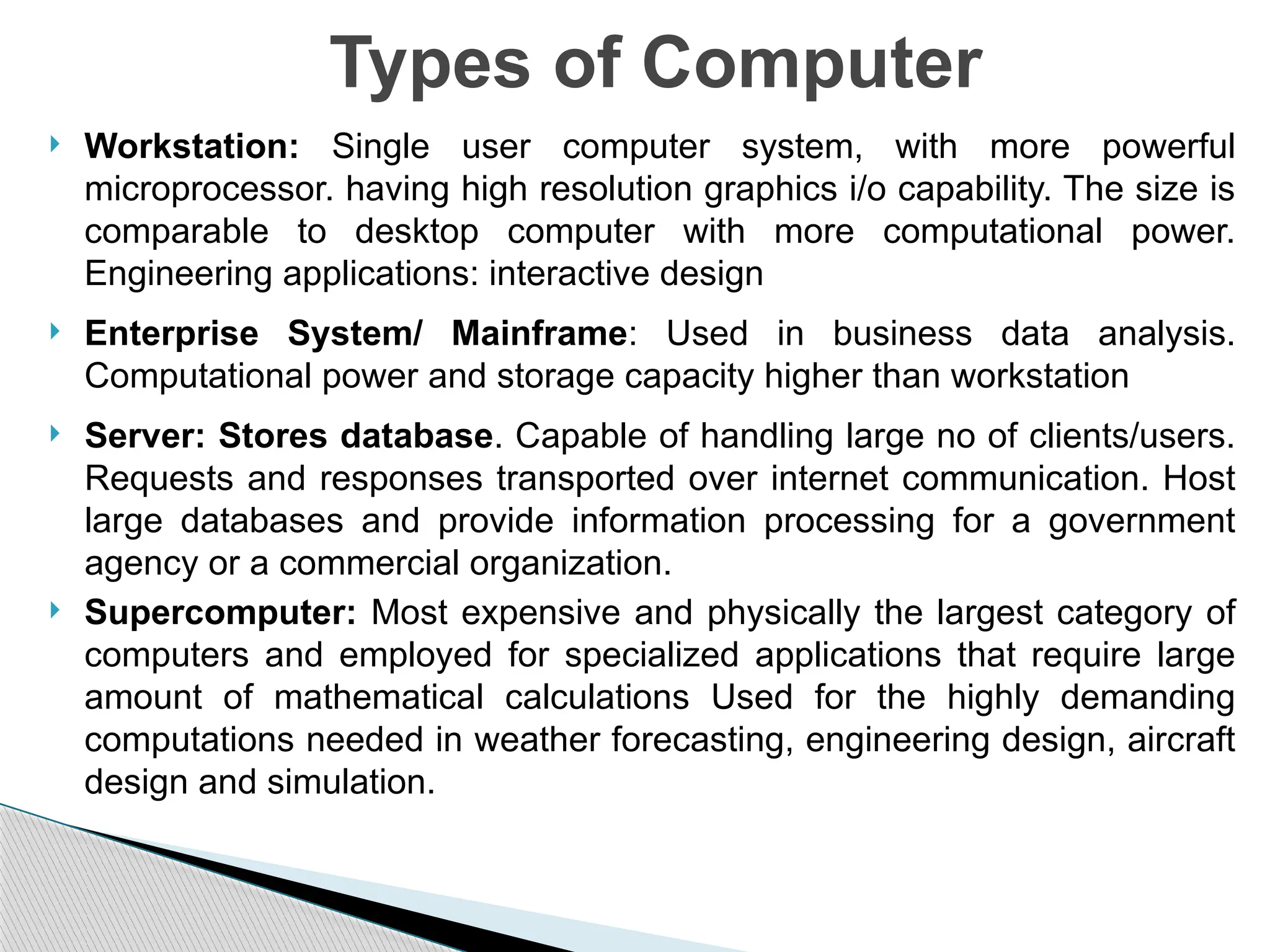
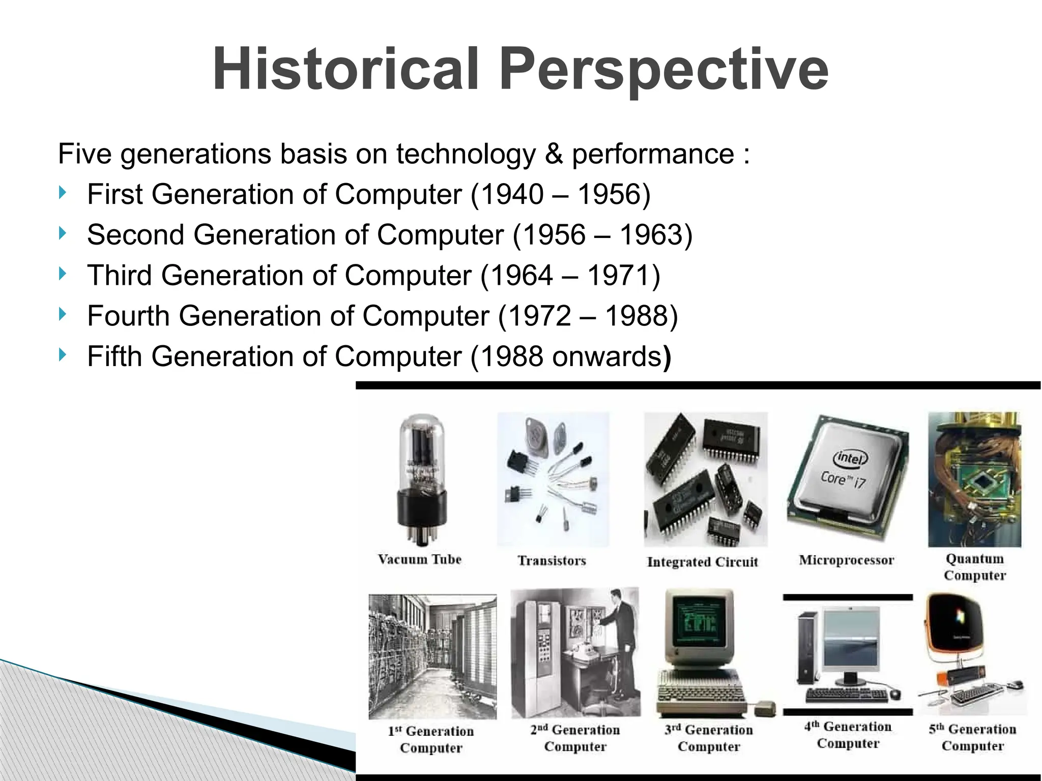
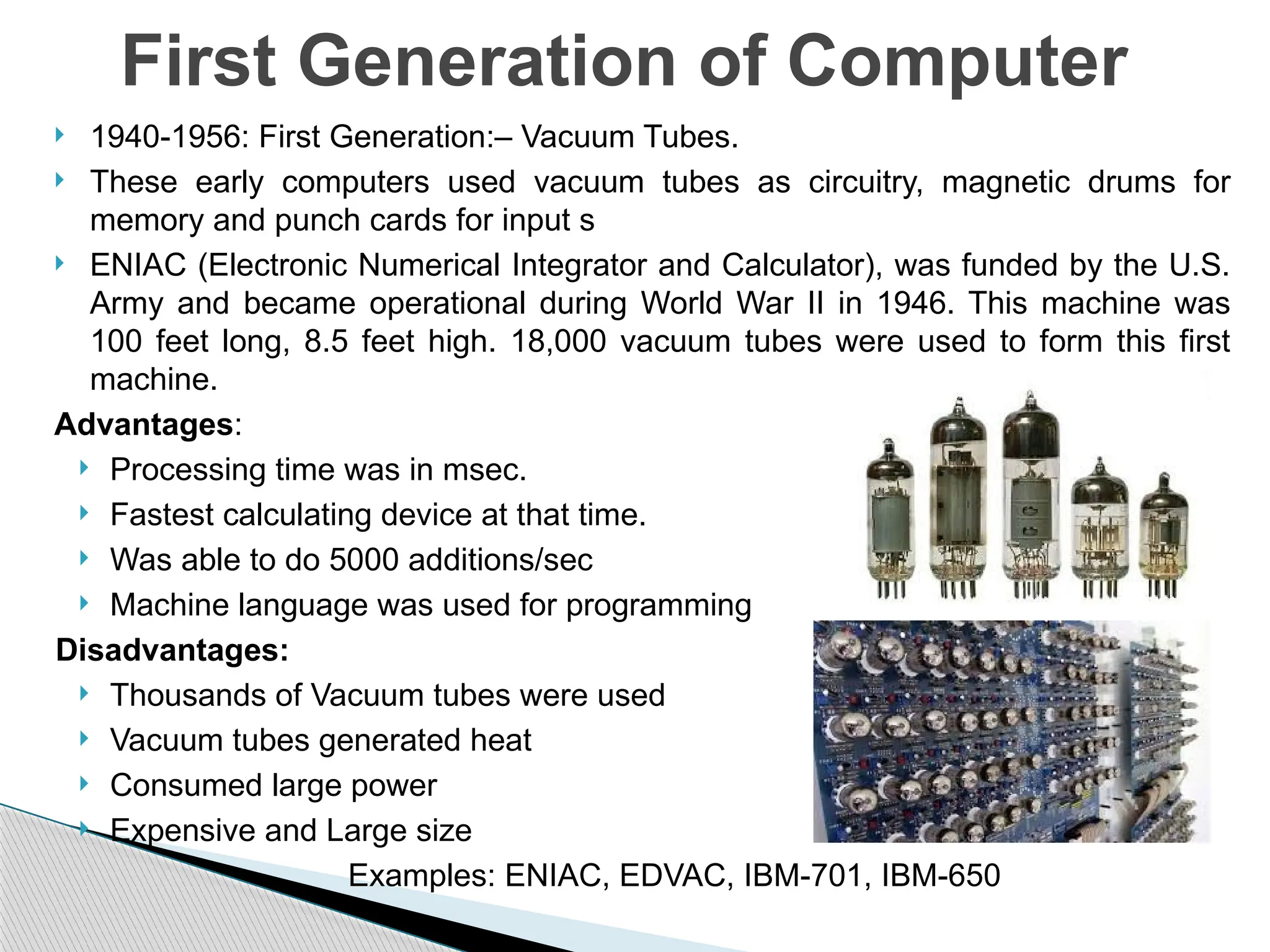
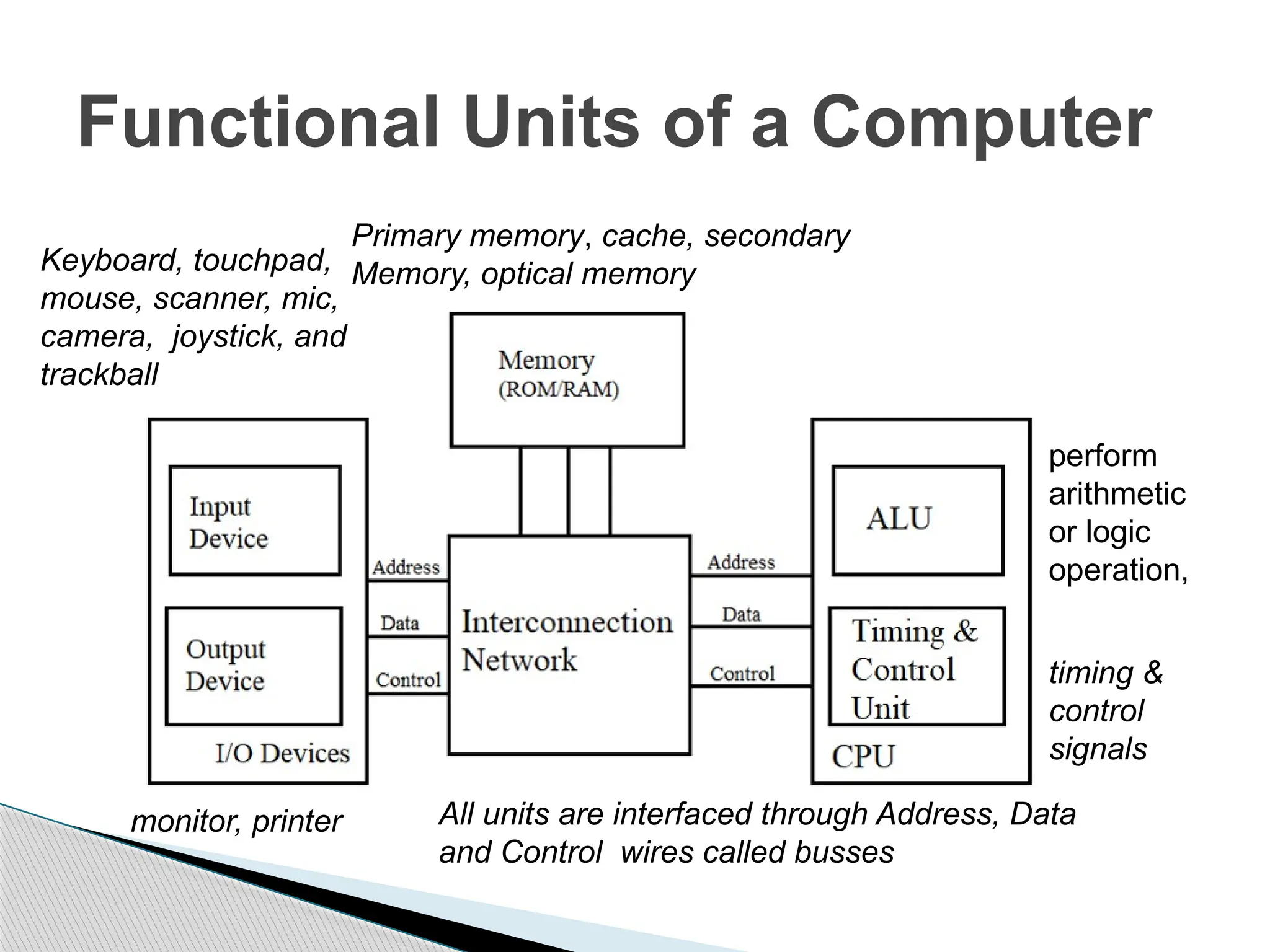
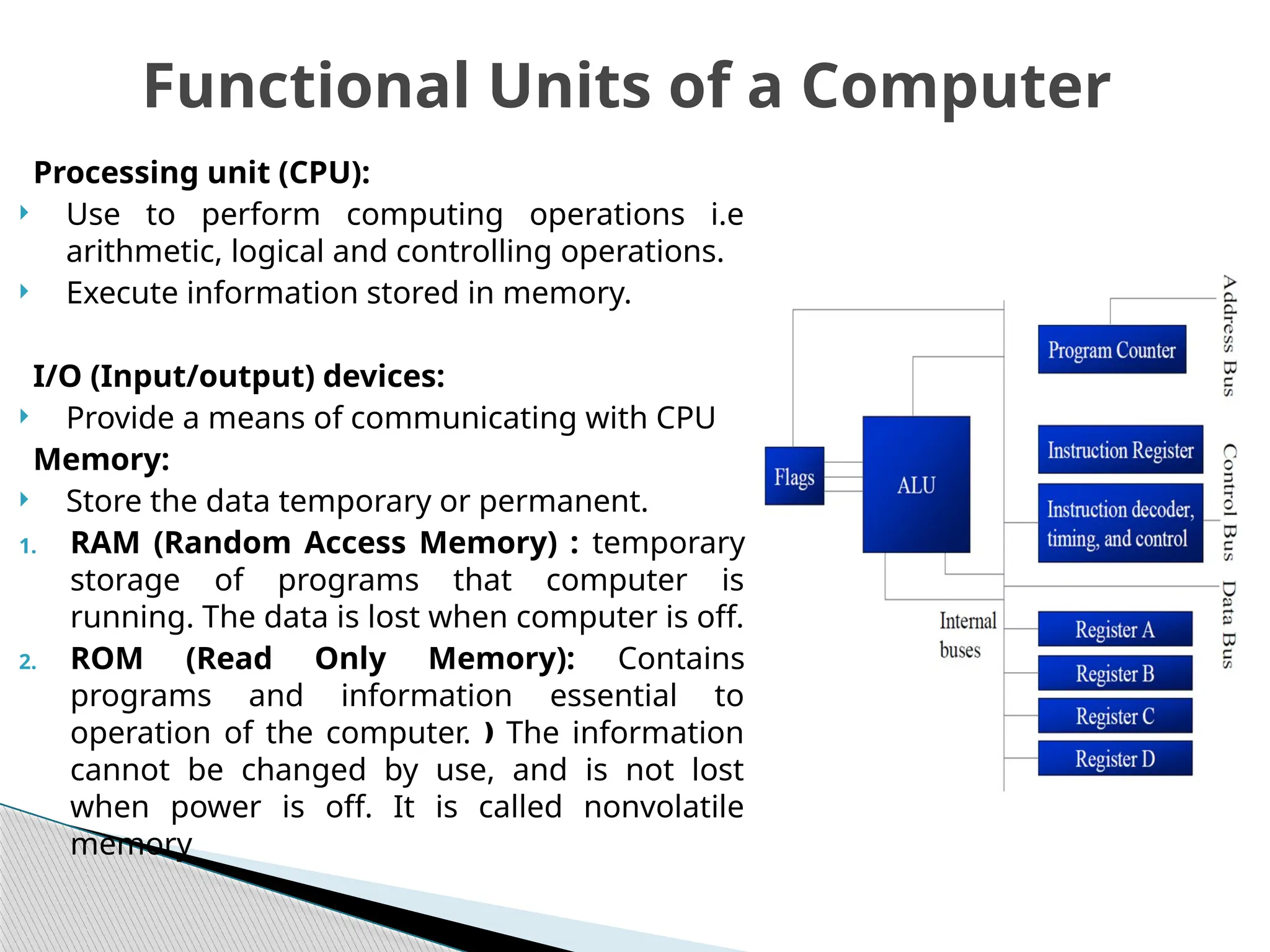
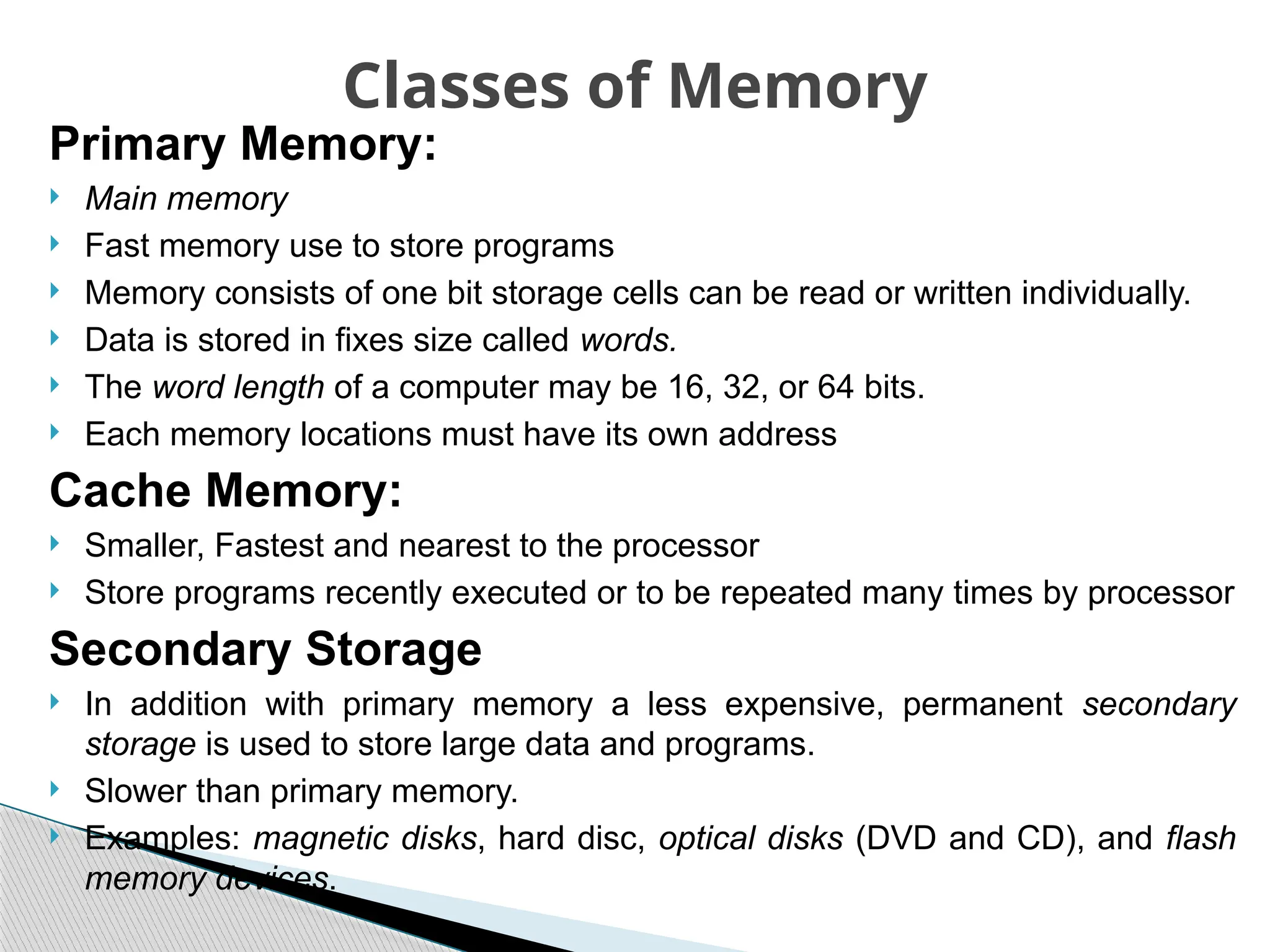
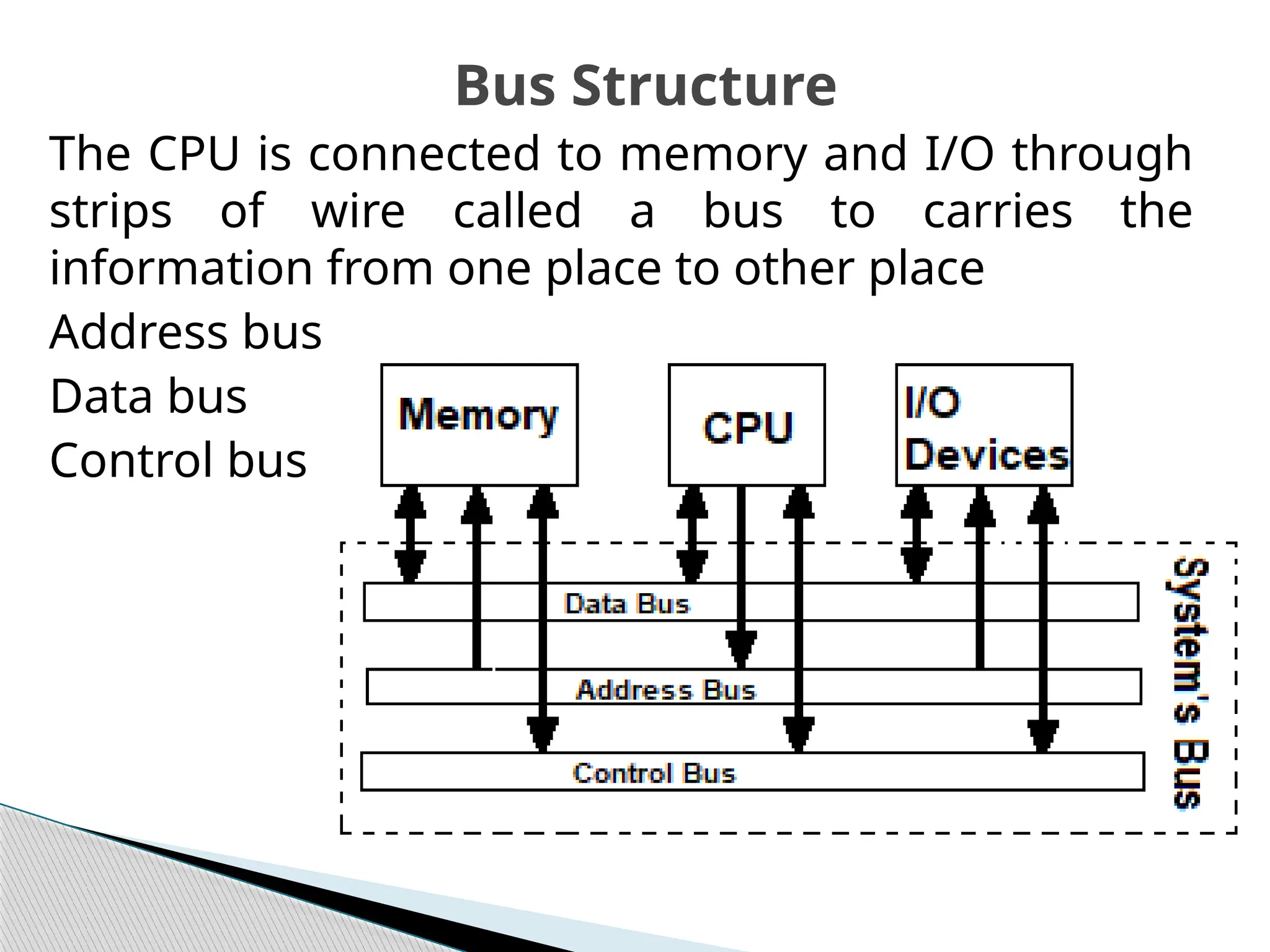
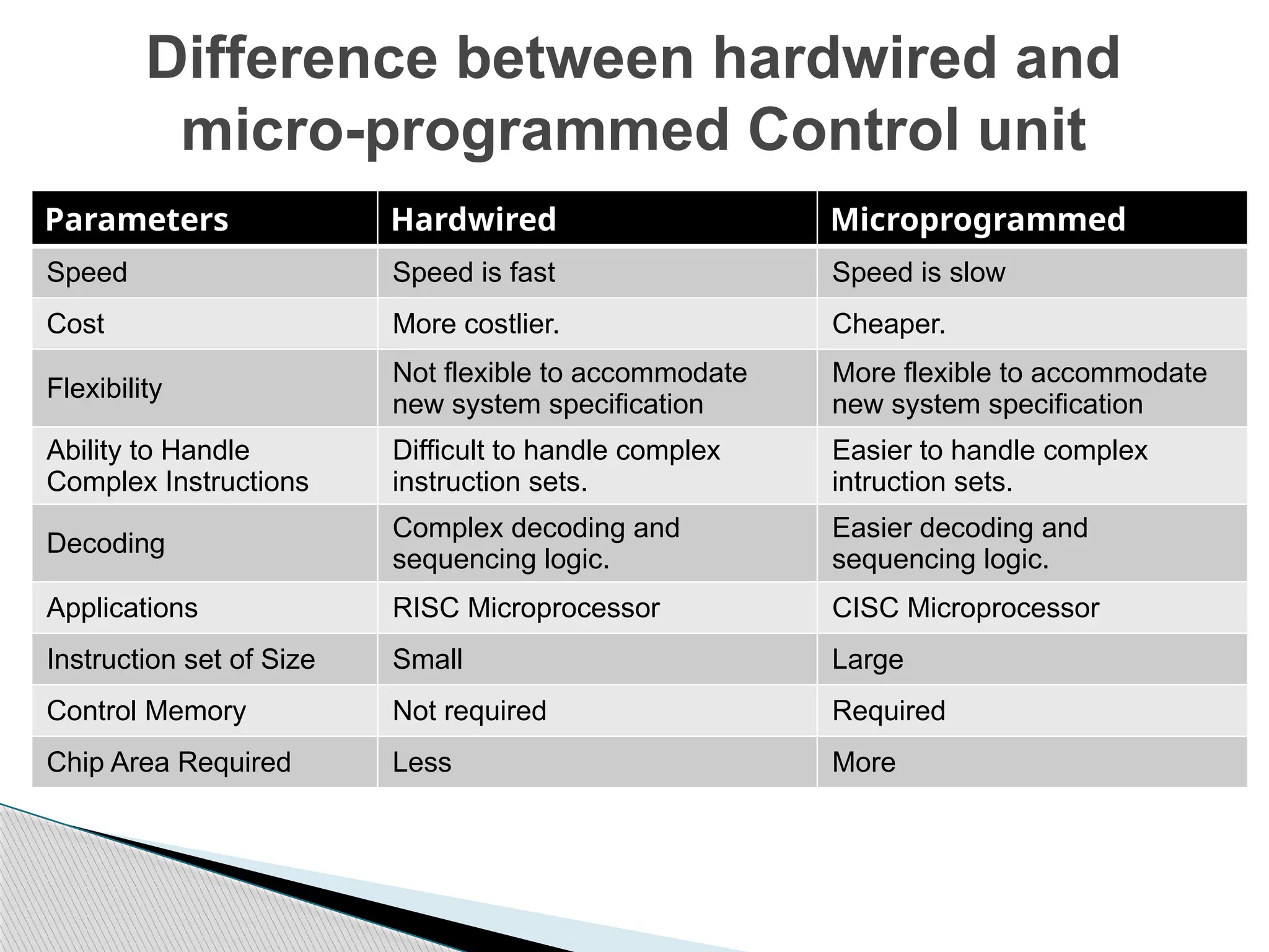
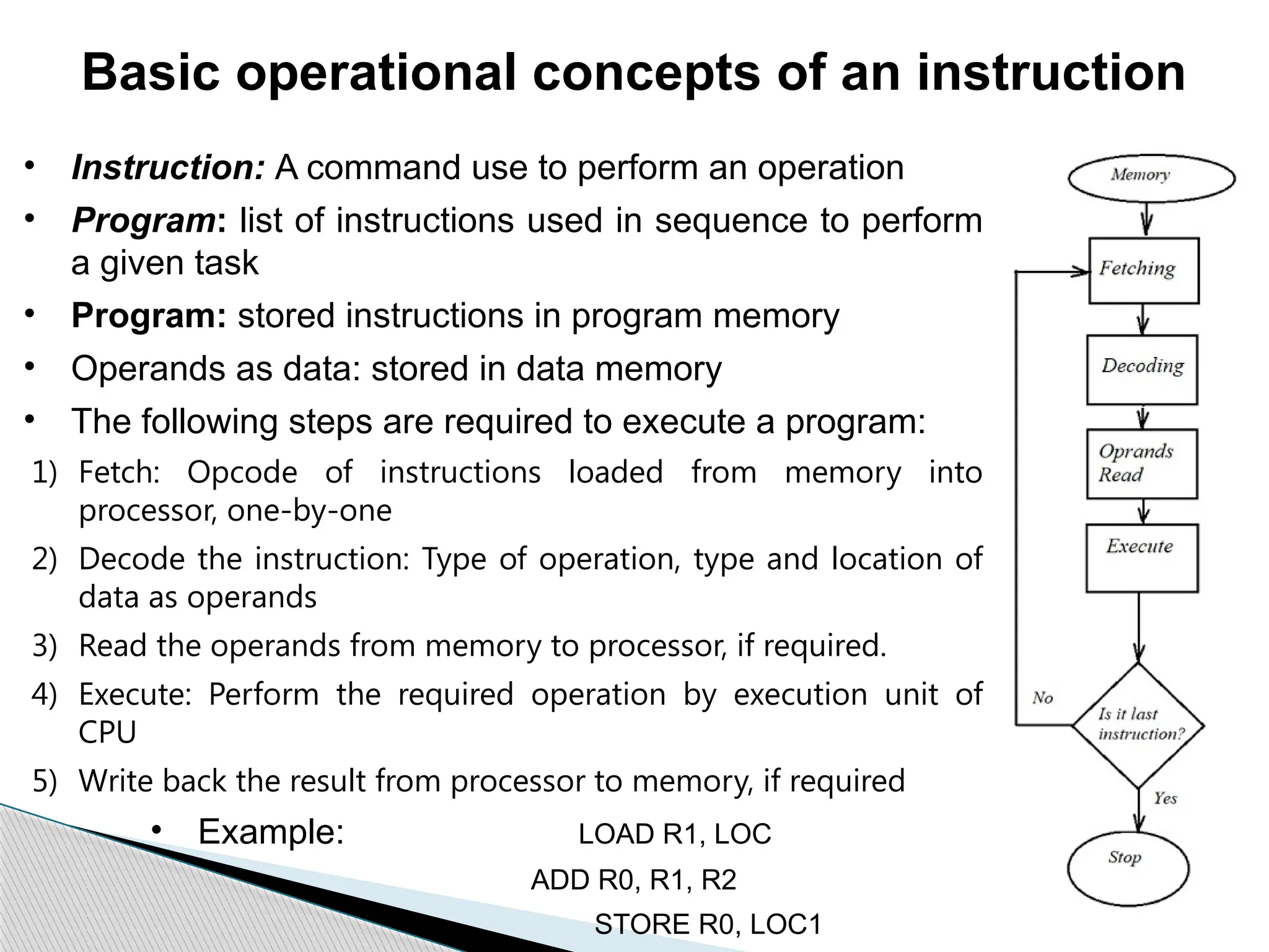
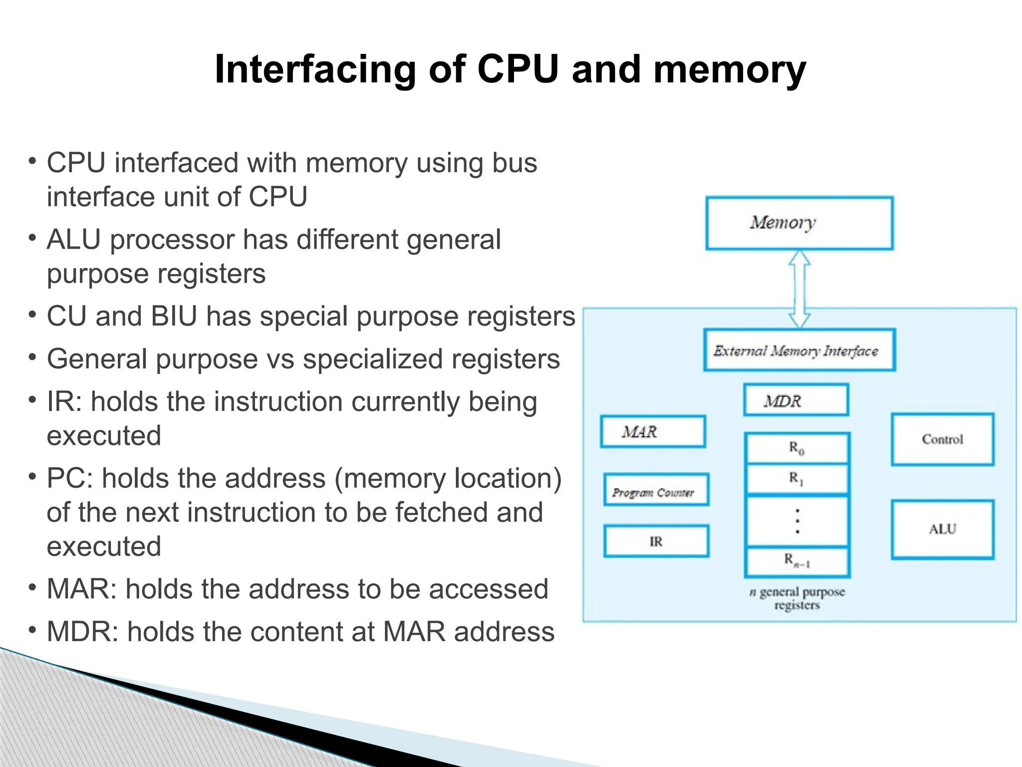
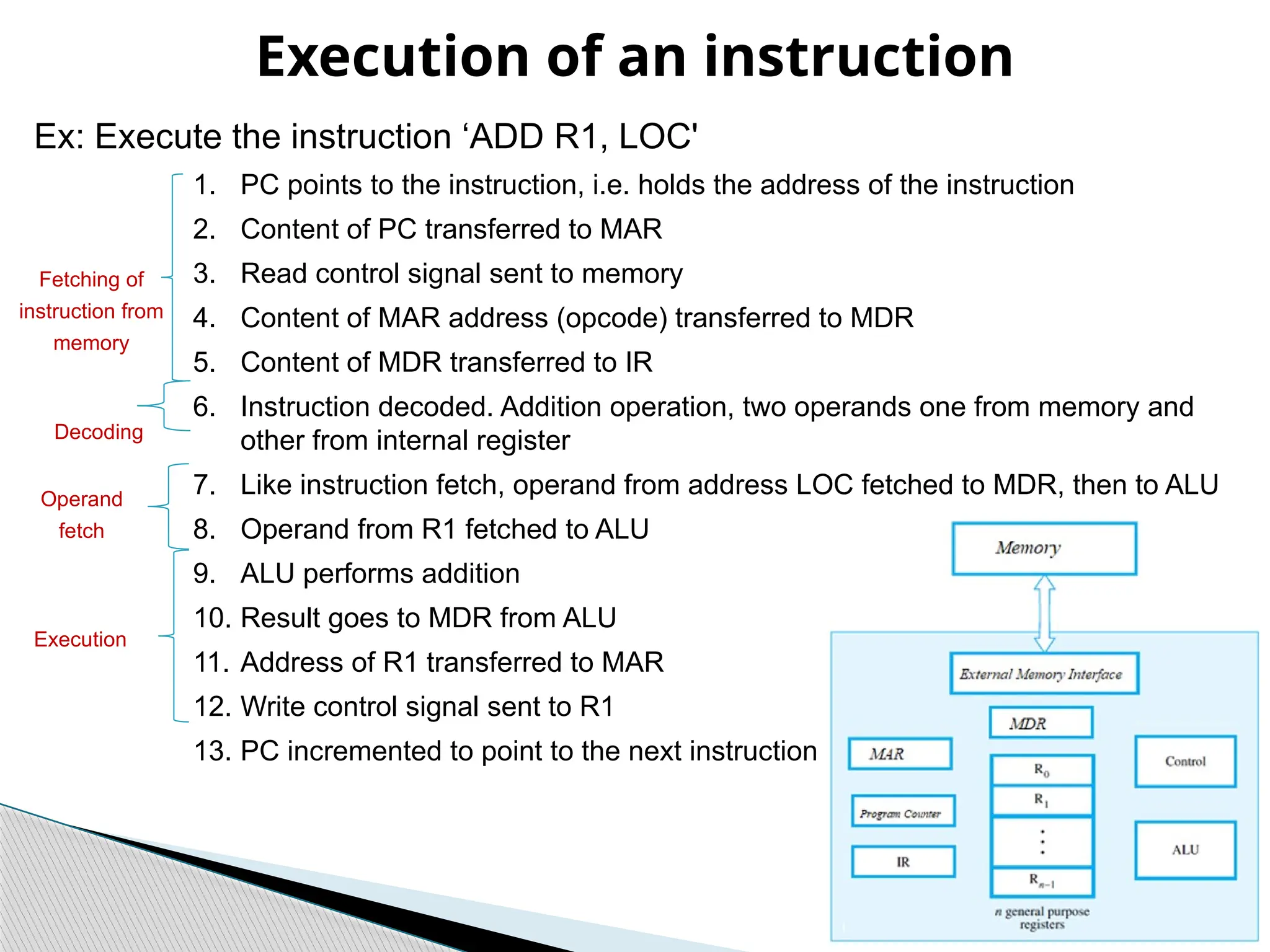
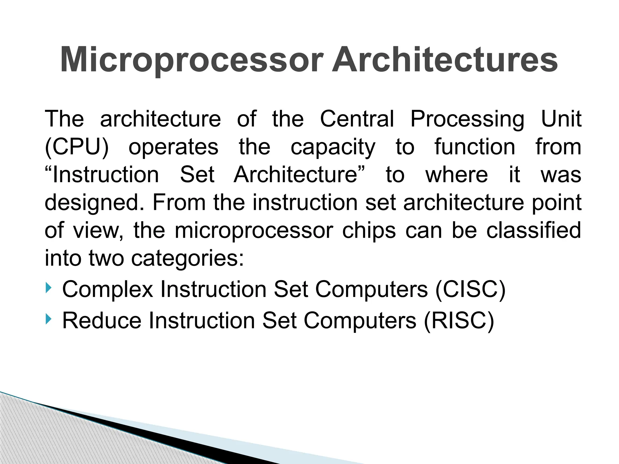
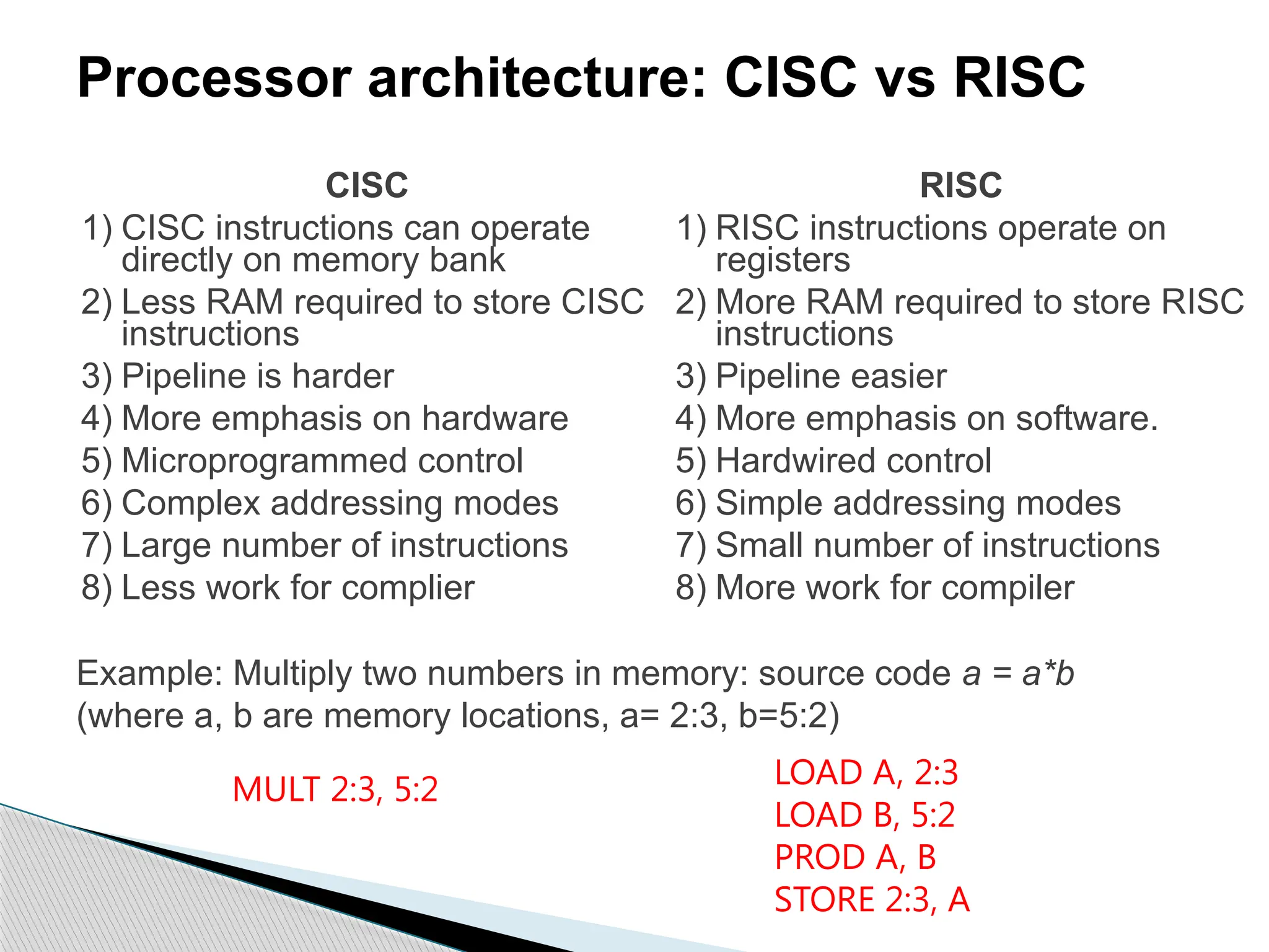
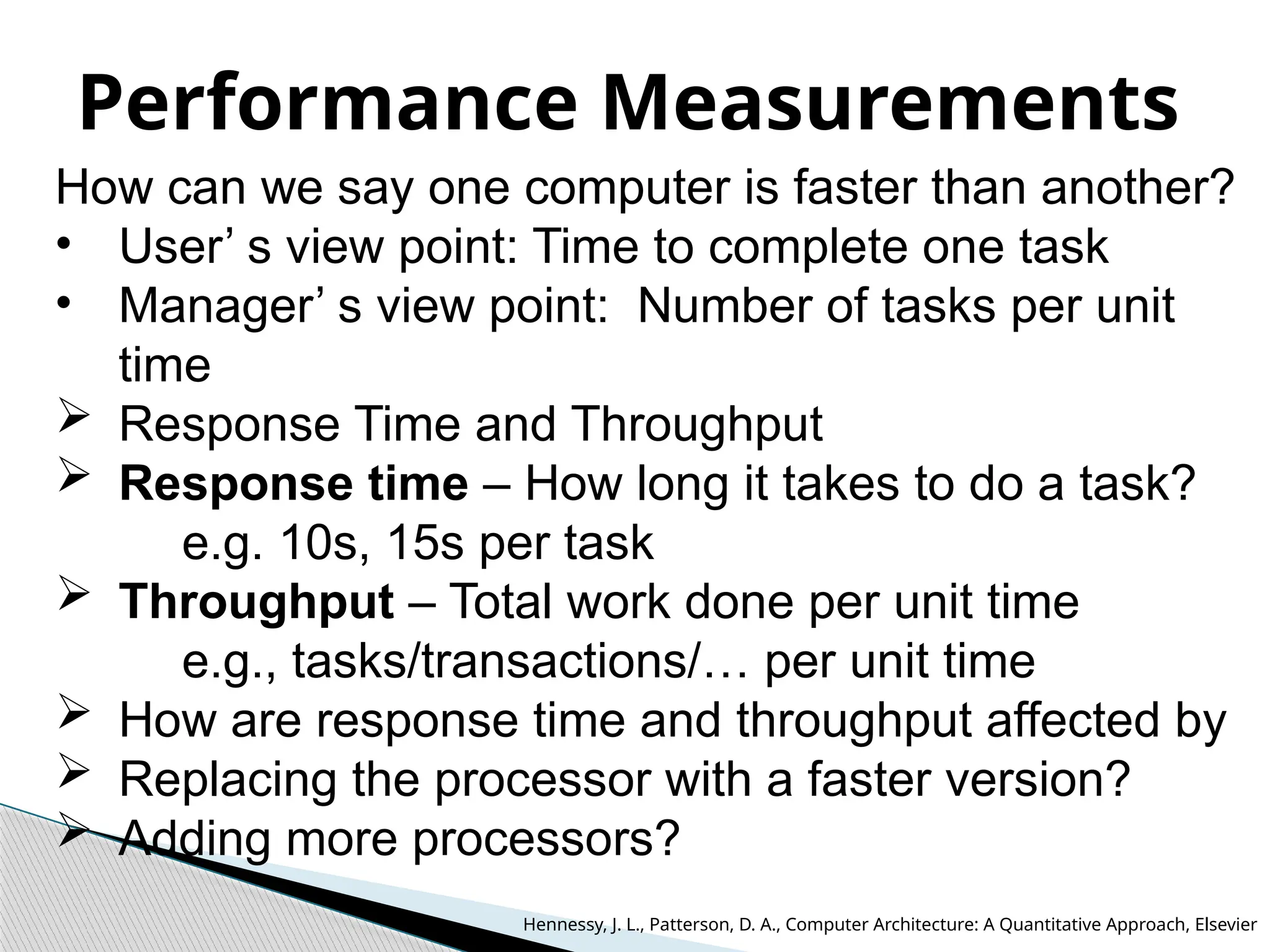
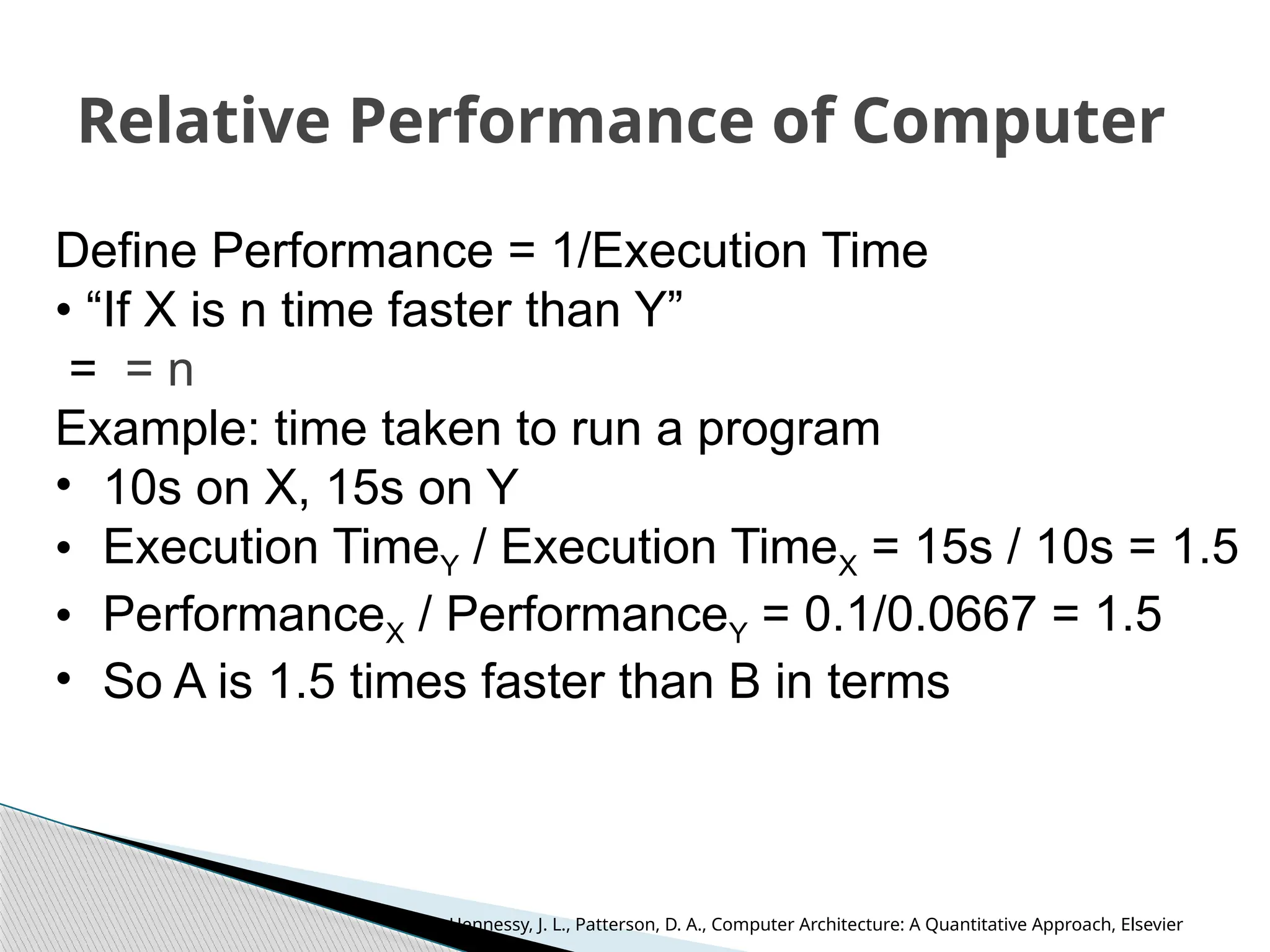
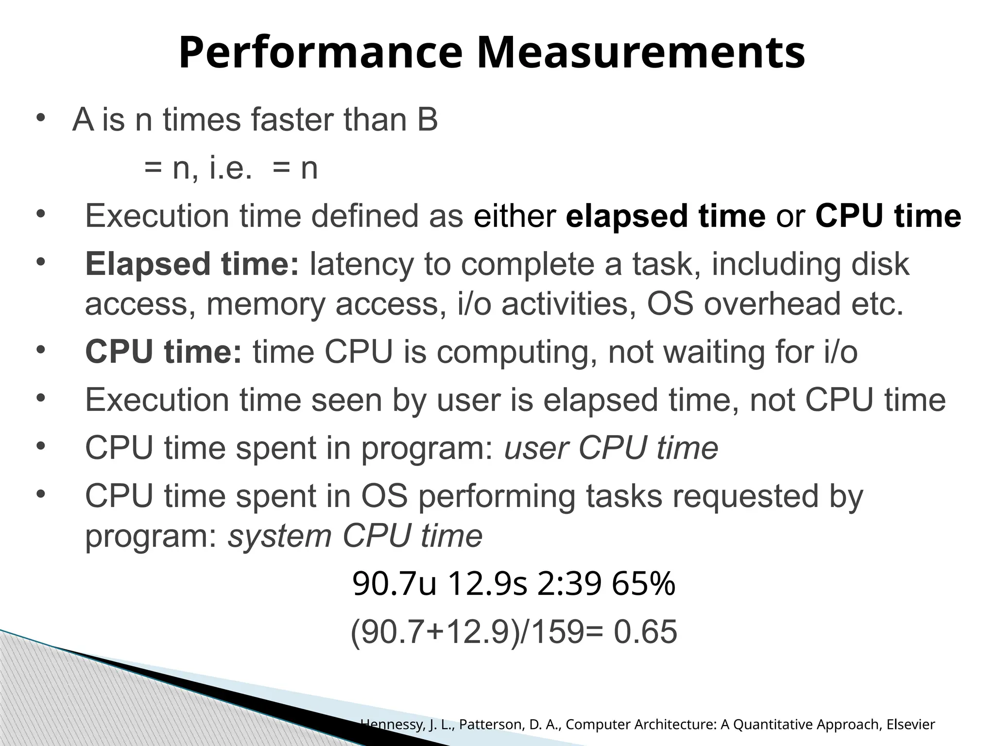
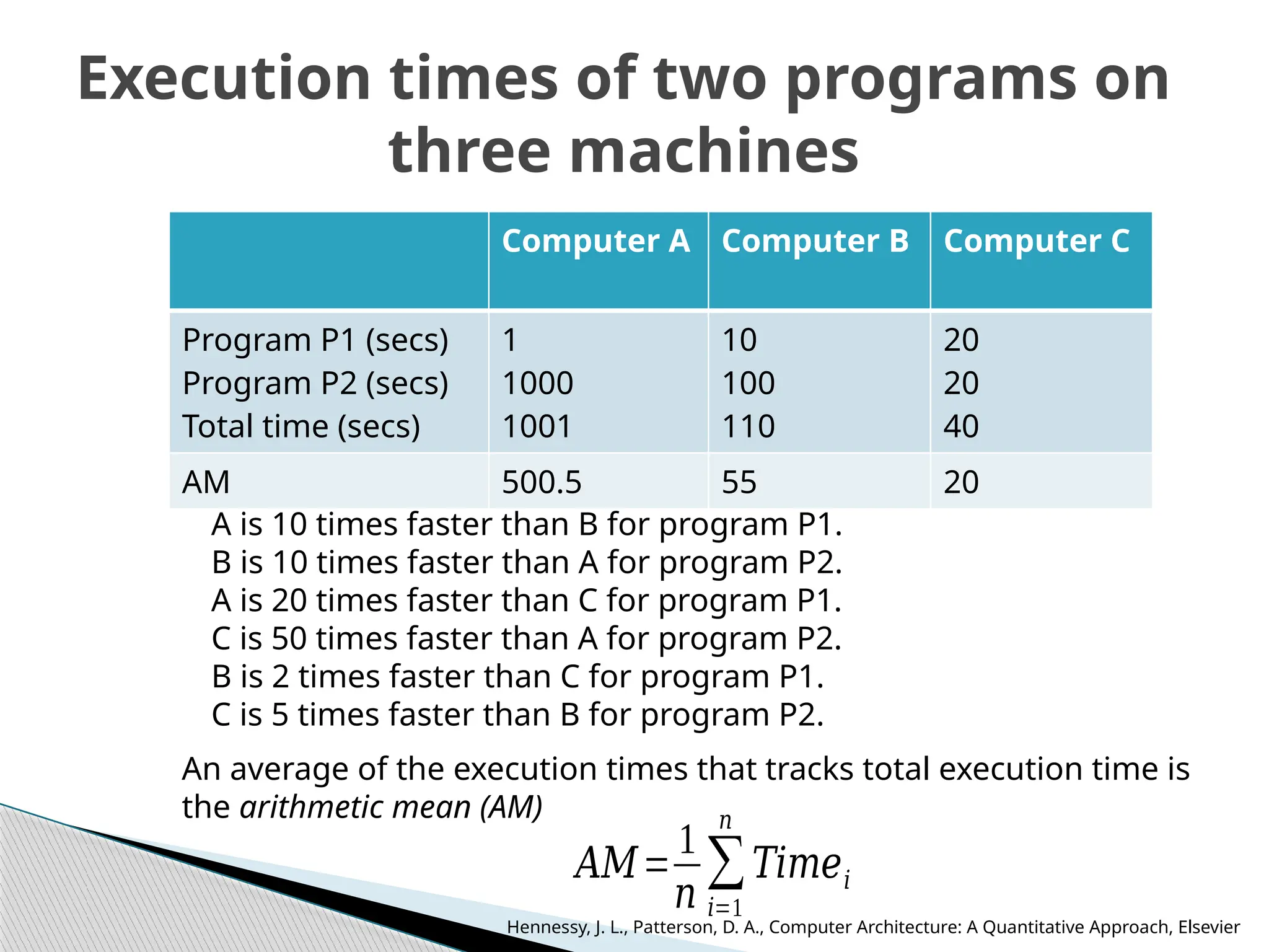
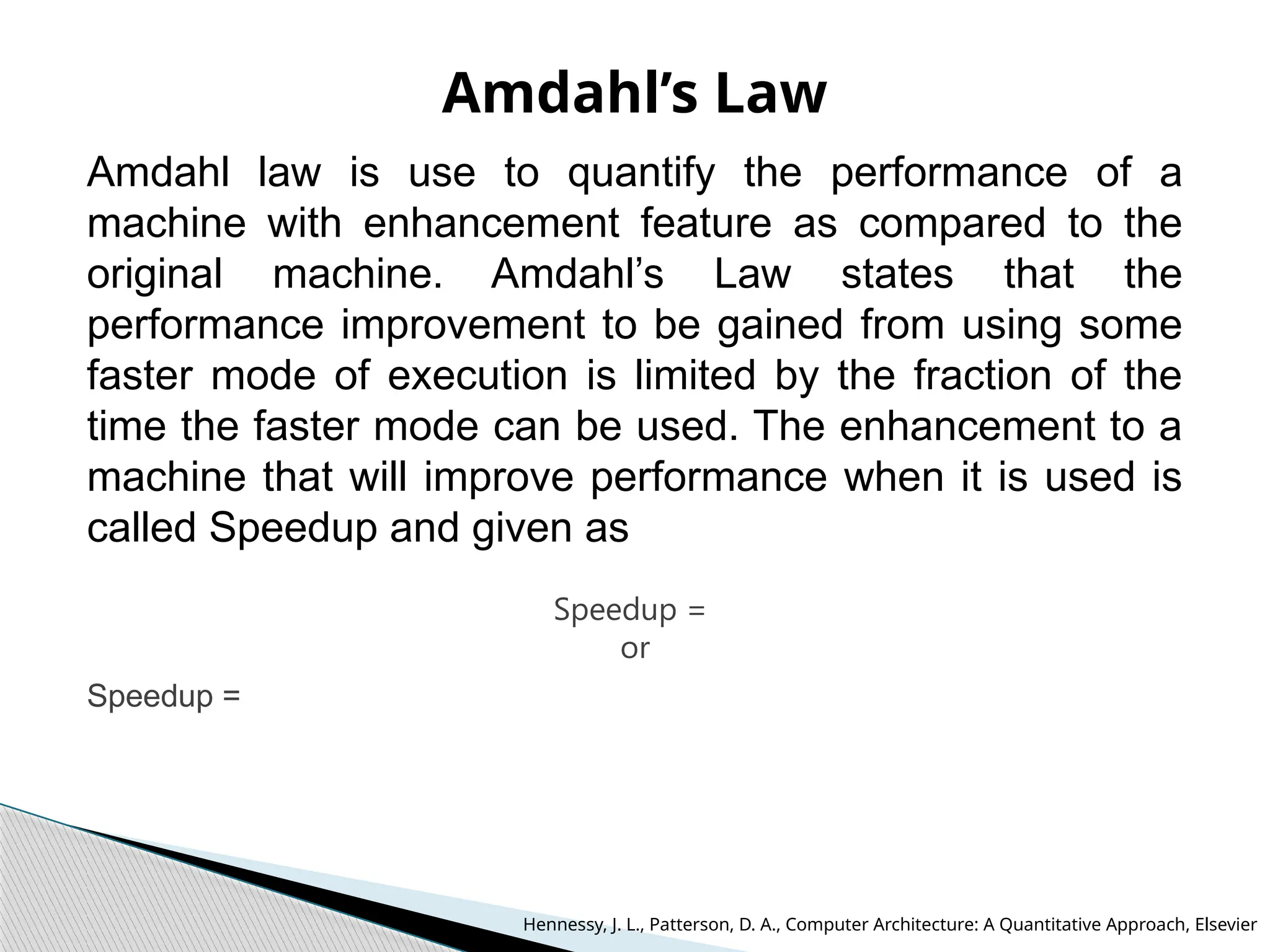
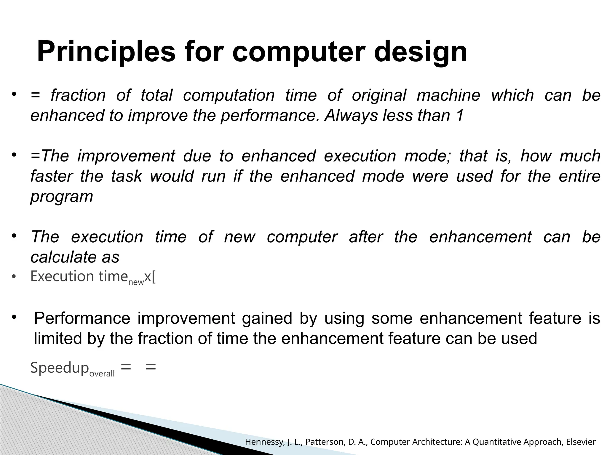
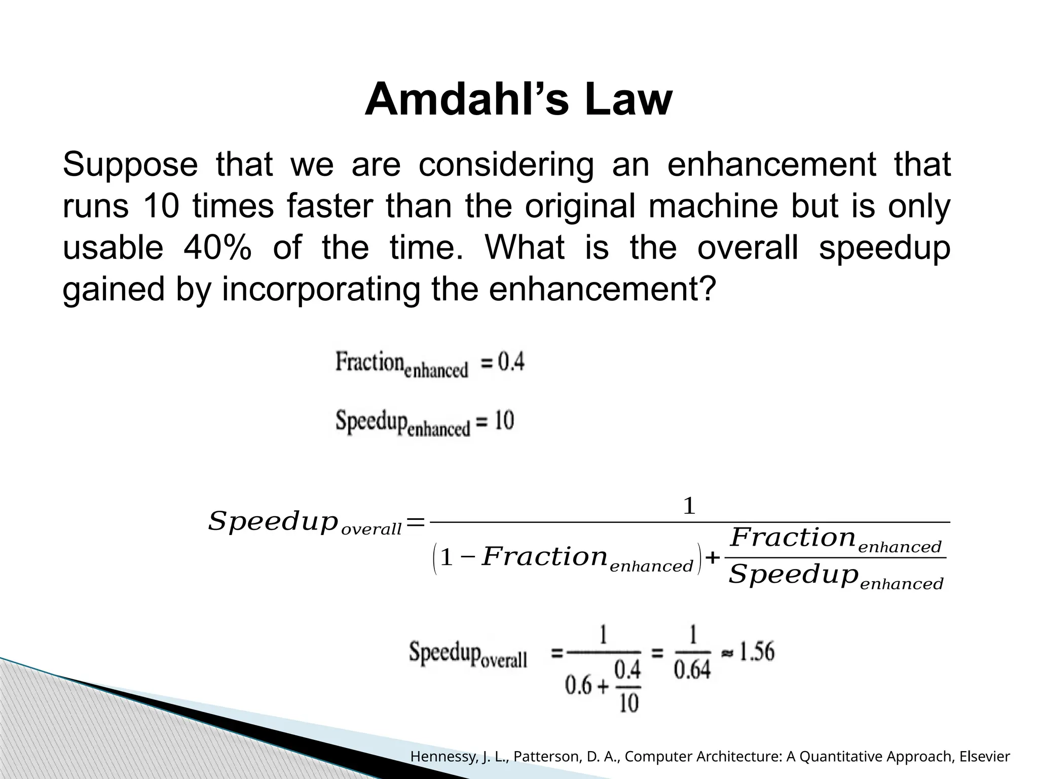
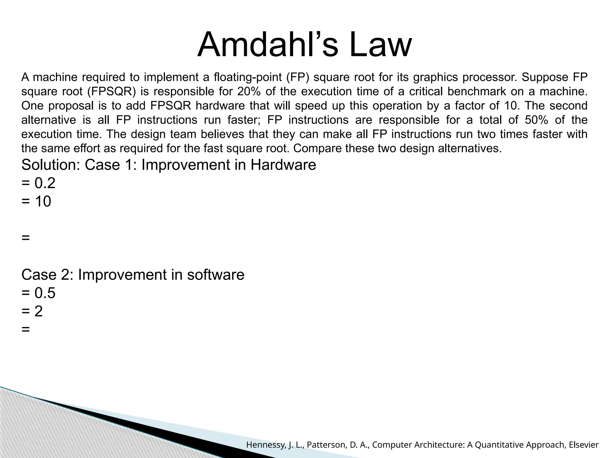
Computer Architecture
UEC509
Dr. Karmjit Singh Sandha
Associate Professor and Associate Head, DECE
TIET, Patiala
References:
1. Hennessy, J. L., Patterson, D. A., Computer Architecture: A Quantitative
Approach, Elsevier (2009) 4th ed.
2. Hamacher, V., Carl, Vranesic, Z.G. and Zaky, S.G., Computer Organization,
McGraw-Hill (2002) 2nd ed.
UEC509: COMPUTER ARCHITECURE
L T P Cr
3 1 0 3.5
Course Objectives: To introduce the concept of parallelism followed in the modern RISC
based computers by introducing the basic RISC based DLX architecture. To make the
students understand and implement various performance enhancement methods like
memory optimization, Multiprocessor configurations, Pipelining and interfacing of I/O
structures using interrupts and to enhance the student’s ability to evaluate performance of
these machines by using evaluation methods like CPU time Equation, MIPS rating and
Amdahl’s law.
Fundamentals of Computer Design: Historical Perspective, Computer Types, Von-
Neuman Architecture, Harvard Architecture Functional Units, Basic Operational Concepts,
Bus Structures, Performance metrics, CISC and RISC architectures, Control Unit,
Hardwired and microprogrammed Control unit.
Instruction Set Principles: Classification of Instruction set architectures, Memory
Addressing, Operations in the instruction set, Type and Size of operands, Encoding an
Instruction set, Program Execution, Role of registers, Evaluation stacks and data buffers,
The role of compilers, The DLX Architecture, Addressing modes of DLX architecture,
Instruction format, DLX operations, Effectiveness of DLX.
Pipelining and Parallelism: Idea of pipelining, The basic pipeline for DLX, Pipeline
Hazards, Data hazards, Control Hazards, Design issues of Pipeline Implementation,
Multicycle operations, The MIPS pipeline, Instruction level parallelism, Pipeline Scheduling
and Loop Unrolling, Data, Branch Prediction, Name and Control Dependences, Overcoming
data hazards with dynamic scheduling, Superscalar DLX Architecture, The VLIW Approach.
Syllabus
Memory Hierarchy Design: Introduction, Cache memory, Cache Organization, Write Policies, Reducing
Cache Misses, Cache Associatively Techniques, Reducing Cache Miss Penalty, Reducing Hit Time, Main
Memory Technology, Fast Address Translation, Translation Lookaside buffer Virtual memory, Crosscutting
issues in the design of Memory Hierarchies.
Multiprocessors: Characteristics of Multiprocessor Architectures, Centralized Shared Memory
Architectures, Distributed Shared Memory Architectures, Synchronization, Models of Memory
Consistency.
Input/ Output Organization and Buses: Accessing I/O Devices, Interrupts, Handling Multiple Devices,
Controlling device Requests, Exceptions, Direct Memory Access, Bus arbitration policies, Synchronous
and Asynchronous buses, Parallel port, Serial port, Standard I/O interfaces, Peripheral Component
Interconnect (PCI) bus and its architecture, SCSI Bus, Universal Synchronous Bus (USB) Interface.
Course Learning Outcomes (CLO S): The students will be able to:
1. Understand and analyze a RISC based processor.
2. Understand the concept of parallelism and pipelining.
3. Evaluate the performance of a RISC based machine with an enhancement applied and make a
decision about applicability of that respective enhancement as a design engineer.
4. Understand the memory hierarchy design and optimise the same for best results. Understand how
input/output devices can be interfaced to a processor in serial or parallel with their priority of access
defined.
Text Books:
1. Hennessy, J. L., Patterson, D. A., Computer Architecture: A Quantitative Approach, Elsevier (2009) 4th ed.
2. Hamacher, V., Carl, Vranesic, Z.G. and Zaky, S.G., Computer Organization, McGraw-Hill (2002) 2nd ed.
Reference Books:
1. Murdocca, M. J. and Heuring, V.P., Principles of Computer Architecture, Prentice Hall (1999) 3rd ed.
2. Stephen, A.S., Halstead, R. H., Computation Structure, MIT Press (1999) 2nd ed.
Evaluation Scheme: Will be announced latter on
Syllabus
 Computer involved in personal, professional,
Institutional or business-related activities.
 human being depend on the computer systems.
 Computers save time, labor and resources.
 Carry on 24/7 long-term automation of machines,
robots, and other equipment, and collect data from
sensors and other sources helping to optimize
operations.
 Used in computing services: including servers,
storage, databases, networking, software,
analytics, and intelligence over the internet.
Role of a Computing System
 Personal
 Scientific research
 Business application
 Education
 Entertainment
 Banks
 Cloud
 IoT
 Industry Automation
 Communication
 Engineering
 Medicine
 Games
 Accounting
 And many more……..
Some applications of Computers
 What is Computer Architecture?
 What is need of Computer Architecture course?
Objective of the Course
 Computer architectures represent the means of
interconnectivity for a computer's hardware components as
well as the mode of data transfer and processing.
 Different computer architecture configurations have been
developed to speed up the movement of data, allowing for
increased data processing.
 To incorporate the important attributes for new machine
design to achieve maximum performance and energy
efficiency with in the specified range of cost, power, size
and other constraints.
 To do so the following tasks have to be performed by a
computer designers:
1. Instruction set architecture (ISA)
2. Implementation
Functional organization
What is Computer Architecture?
 Instruction set architecture: ISA includes the specification of
an instruction set and the functional behavior of the hardware
units that implement the instructions.
 Implementation:
 Functional Organization: It deals with high level aspects of
computer designer such as memory system, memory interfacing
and design of CPU
 Computer hardware: Computer hardware consists of electronic
circuits, RAM, ROM, displays, electromechanical devices, and
communication facilities. (Structural Design of a building).
 Hardware Implementation: Execution or practice to plan,
design, model, develop a computing machine to execute the
task using ISA.
What is Computer Architecture?
 Computer architecture: Architecture of building
 Computer hardware: Structural Design of a
building
 Computer architecture includes the specification of
an instruction set and the functional behavior of
the hardware units that implement the instructions.
 Computer hardware consists of electronic circuits,
magnetic and optical storage devices, displays,
electromechanical devices, and communication
facilities.
What is Computer Architecture?
 To understand the concept of computing machine
designed, construct and operate.
 To understand the set of rules and methods
describing functionality, organization, and
implementation of a computer system
 How to design and implement a computing machine
to get best performance in terms of speed,
efficiency, power consumption and throughput
 To develop machine with optimize cost, size and
easy to use.
What is need of Computer Architecture course?
Computer can be classified into six general types on the basis of
size, cost, computational capacity, and applications:
Personal computers/Desktop Computer:
 Used in homes, educational institutions, and business and
engineering office settings, primarily for dedicated individual use.
 Operational units (processing unit, storage unit, video o/p, audio
o/p, keyboard) are clearly different
 Examples: Desktop, Laptop, and Notebook computers
Embedded computers:
 Operational units are packed in a compact size for a specific
application or similar type of applications.
 Embedded systems applications include industrial and home
automation, appliances, telecommunication products, and
vehicles.
 Examples: Mobiles, Automobile industry, home appliances
Types of Computer
 Workstation: Single user computer system, with more powerful
microprocessor. having high resolution graphics i/o capability. The size is
comparable to desktop computer with more computational power.
Engineering applications: interactive design
 Enterprise System/ Mainframe: Used in business data analysis.
Computational power and storage capacity higher than workstation
 Server: Stores database. Capable of handling large no of clients/users.
Requests and responses transported over internet communication. Host
large databases and provide information processing for a government
agency or a commercial organization.
 Supercomputer: Most expensive and physically the largest category of
computers and employed for specialized applications that require large
amount of mathematical calculations Used for the highly demanding
computations needed in weather forecasting, engineering design, aircraft
design and simulation.
Types of Computer
Five generations basis on technology & performance :
 First Generation of Computer (1940 – 1956)
 Second Generation of Computer (1956 – 1963)
 Third Generation of Computer (1964 – 1971)
 Fourth Generation of Computer (1972 – 1988)
 Fifth Generation of Computer (1988 onwards)
Historical Perspective
 1940-1956: First Generation:– Vacuum Tubes.
 These early computers used vacuum tubes as circuitry, magnetic drums for
memory and punch cards for input s
 ENIAC (Electronic Numerical Integrator and Calculator), was funded by the U.S.
Army and became operational during World War II in 1946. This machine was
100 feet long, 8.5 feet high. 18,000 vacuum tubes were used to form this first
machine.
Advantages:
 Processing time was in msec.
 Fastest calculating device at that time.
 Was able to do 5000 additions/sec
 Machine language was used for programming
Disadvantages:
 Thousands of Vacuum tubes were used
 Vacuum tubes generated heat
 Consumed large power
 Expensive and Large size
Examples: ENIAC, EDVAC, IBM-701, IBM-650
First Generation of Computer
 1956 – 1963: Second Generation was based on Transistors.
 Transistor is a based on semiconductor material invented in 1947 Bell Labs.
 Transistors were cheaper, low power, more compact in size, more reliable and
faster than the first generation.
 magnetic cores for primary memory, magnetic tape and magnetic disks as
secondary storage devices.
Advantages:
 Smaller in size
 Faster than 1st
gen.
 Consumed less power
 Instructions saved in memory
 Machine and assembly language (COBOL, FORTRAN).
Disadvantages:
 Air-conditioning required
 Not used as personal system
 Used as commercial purpose
Examples: IBM7049 Series, CDC 3600
IBM1600 series
Second Generation of Computer
 1964 – 1971: Third Generation was based on Integrated Circuits.
 In IC, transistors with small in size were placed on a silicon chip.
 A single IC has many transistors, resistors, and capacitors along
with the associated circuitry.
Main features of 3rd
generation:
 Smaller and faster
 Cheaper than 2nd
Generation
 More reliable in comparison to previous two generations
 Generated less heat
 Lesser maintenance
 Used with I/O devices like keyboard, monitor
 Used operating systems
 Large production and popular
Example: IBM system/360 & 370 IBM, PDP-8, DEC UNIVAC-8, UNIVAC 9000
Third Generation of Computer
 1972 – 1988: Fourth Generation: Microprocessors based computer
was introduced around 1971.
 More than 100 thousands transistors fabricated on single chip
 The Intel corporation introduced 4004, a four bit microprocessor
followed by 8008, 8085,8086 and many more
Main Features:
 Microprocessor based on VLSI technology
 Millions of transistors on a single chip
 Small in size and portable
 High speed
 Accurate and Reliable
 Large memory can be interfaced
Examples: A series of Intel processor, AMD processors, Motorola’s
processors
Fourth Generation of computers
 Fifth generation computers are used for Artificial Intelligence
based applications such as voice, face and other biometric
recognition.
 1988-onwards.
 ULSI microprocessor based
 Nano-meter technology nodes used for fabrication
 high-level languages like C and C++, Java, .Net etc.
 Faster and cheaper
 Intelligent computers
 Parallel Processing
 Have thinking and self analysis
 Examples: Desktop, Laptop, NoteBook, UltraBook,
Fifth Generation of computers
Functional Units of a Computer
Primary memory, cache, secondary
Memory, optical memory
monitor, printer
timing &
control
signals
Keyboard, touchpad,
mouse, scanner, mic,
camera, joystick, and
trackball
perform
arithmetic
or logic
operation,
All units are interfaced through Address, Data
and Control wires called busses
Processing unit (CPU):
 Use to perform computing operations i.e
arithmetic, logical and controlling operations.
 Execute information stored in memory.
I/O (Input/output) devices:
 Provide a means of communicating with CPU
Memory:
 Store the data temporary or permanent.
1. RAM (Random Access Memory) : temporary
storage of programs that computer is
running. The data is lost when computer is off.
2. ROM (Read Only Memory): Contains
programs and information essential to
operation of the computer. The information
ƒ
cannot be changed by use, and is not lost
when power is off. It is called nonvolatile
memory
Functional Units of a Computer
Primary Memory:
 Main memory
 Fast memory use to store programs
 Memory consists of one bit storage cells can be read or written individually.
 Data is stored in fixes size called words.
 The word length of a computer may be 16, 32, or 64 bits.
 Each memory locations must have its own address
Cache Memory:
 Smaller, Fastest and nearest to the processor
 Store programs recently executed or to be repeated many times by processor
Secondary Storage
 In addition with primary memory a less expensive, permanent secondary
storage is used to store large data and programs.
 Slower than primary memory.
 Examples: magnetic disks, hard disc, optical disks (DVD and CD), and flash
memory devices.
Classes of Memory
The CPU is connected to memory and I/O through
strips of wire called a bus to carries the
information from one place to other place
Address bus
Data bus
Control bus
Bus Structure
Address Bus:
 To recognized any I/O device or memory location by
processor.
 Assign address must be unique.
 Processor send the address on address lines and decoding
circuit will find respective device.
 More number of address bus means more number of
devices can be interfaced with CPU.
2m
=n
m: number of address lines
n: number
 The address bus is unidirectional
Data Bus:
 Required data transfer or received through data bus.
It indicates the data handling capacity of CPU.
 More data buses mean a more expensive CPU and
computer
 The data bus is bidirectional
Control bus:
 Use to decide the direction of data, either transfer or
received.
Role of Address, data and control busses
 The architectures of computer are refers to the
arrangement of CPU with program and data
memory. Two types of architectures are used two
interface the memory units with the processors:
 Von Neumann
 Harvard Architectures
Architectures of Computer
 It was proposed by John von Neumann to
decide the structure, layout, interaction,
cooperation, implementation and activity for the
whole computer as a system. The Von Neumann
Architecture is having following features:
 A memory, ALU, control unit, input and output
devices
 CPU and memory is interfaced to each other
through one set of address and data bus
 Slower in execution speed.
 No parallel processing of program.
 Only one information can be accessed at one
time.
Von Neumann Architecture/Princeton
 Harvard University introduced a slightly
different architecture in which memories for
data and instruction was separately interfaced
with different set of data and address busses in
1947. This concept is known as the Harvard
 Parallel access to data and instructions.
 Data and instructions are accessed the same
way.
 Both memories can use different cell sizes.
architecture.
 Speed of execution is high.
 Complex and costly.
 Development of the Control Unit is expensive
and needs more time
Harvard Architecture
Hardwired and micro-programmed Control unit
Control unit generates control signal to perform the different
operations for CPU. Two techniques are used for control unit
 Hardwired Control Unit
 Microprogrammed Control Unit.
Hardwired Control Unit:
It is implemented using logical circuits (using gates, flip-flops,
decoders etc.) as the hardware unit. This organization is very
complicated for large control units.
Microprogrammed Control Unit:
A microprogrammed control unit is implemented using programming
approach. A sequence of micro control operations are carried out by
executing programs consisting of micro-instructions.
Difference between hardwired and
micro-programmed Control unit
Parameters Hardwired Microprogrammed
Speed Speed is fast Speed is slow
Cost More costlier. Cheaper.
Flexibility
Not flexible to accommodate
new system specification
More flexible to accommodate
new system specification
Ability to Handle
Complex Instructions
Difficult to handle complex
instruction sets.
Easier to handle complex
intruction sets.
Decoding
Complex decoding and
sequencing logic.
Easier decoding and
sequencing logic.
Applications RISC Microprocessor CISC Microprocessor
Instruction set of Size Small Large
Control Memory Not required Required
Chip Area Required Less More
Basic operational concepts
Computer Architecture
UEC509
Basic operational concepts of an instruction
• Instruction: A command use to perform an operation
• Program: list of instructions used in sequence to perform
a given task
• Program: stored instructions in program memory
• Operands as data: stored in data memory
• The following steps are required to execute a program:
1) Fetch: Opcode of instructions loaded from memory into
processor, one-by-one
2) Decode the instruction: Type of operation, type and location of
data as operands
3) Read the operands from memory to processor, if required.
4) Execute: Perform the required operation by execution unit of
CPU
5) Write back the result from processor to memory, if required
• Example: LOAD R1, LOC
ADD R0, R1, R2
STORE R0, LOC1
Interfacing of CPU and memory
• CPU interfaced with memory using bus
interface unit of CPU
• ALU processor has different general
purpose registers
• CU and BIU has special purpose registers
• General purpose vs specialized registers
• IR: holds the instruction currently being
executed
• PC: holds the address (memory location)
of the next instruction to be fetched and
executed
• MAR: holds the address to be accessed
• MDR: holds the content at MAR address
Execution of an instruction
Ex: Execute the instruction ‘ADD R1, LOC'
1. PC points to the instruction, i.e. holds the address of the instruction
2. Content of PC transferred to MAR
3. Read control signal sent to memory
4. Content of MAR address (opcode) transferred to MDR
5. Content of MDR transferred to IR
6. Instruction decoded. Addition operation, two operands one from memory and
other from internal register
7. Like instruction fetch, operand from address LOC fetched to MDR, then to ALU
8. Operand from R1 fetched to ALU
9. ALU performs addition
10. Result goes to MDR from ALU
11. Address of R1 transferred to MAR
12. Write control signal sent to R1
13. PC incremented to point to the next instruction
Fetching of
instruction from
memory
Operand
fetch
Execution
Decoding
The architecture of the Central Processing Unit
(CPU) operates the capacity to function from
“Instruction Set Architecture” to where it was
designed. From the instruction set architecture point
of view, the microprocessor chips can be classified
into two categories:
 Complex Instruction Set Computers (CISC)
 Reduce Instruction Set Computers (RISC)
Microprocessor Architectures
Processor architecture: CISC vs RISC
Example: Multiply two numbers in memory: source code a = a*b
(where a, b are memory locations, a= 2:3, b=5:2)
MULT 2:3, 5:2 LOAD A, 2:3
LOAD B, 5:2
PROD A, B
STORE 2:3, A
CISC
1) CISC instructions can operate
directly on memory bank
2) Less RAM required to store CISC
instructions
3) Pipeline is harder
4) More emphasis on hardware
5) Microprogrammed control
6) Complex addressing modes
7) Large number of instructions
8) Less work for complier
RISC
1) RISC instructions operate on
registers
2) More RAM required to store RISC
instructions
3) Pipeline easier
4) More emphasis on software.
5) Hardwired control
6) Simple addressing modes
7) Small number of instructions
8) More work for compiler
Performance Parameter of a
Computing Machine
Course: Computer Architecture
Presented by:
Dr. Karmjit Singh Sandha
Associate Professor, DECE
TIET, Patiala
Performance Measurements
How can we say one computer is faster than another?
• User’ s view point: Time to complete one task
• Manager’ s view point: Number of tasks per unit
time
 Response Time and Throughput
 Response time – How long it takes to do a task?
e.g. 10s, 15s per task
 Throughput – Total work done per unit time
e.g., tasks/transactions/… per unit time
 How are response time and throughput affected by
 Replacing the processor with a faster version?
 Adding more processors?
Hennessy, J. L., Patterson, D. A., Computer Architecture: A Quantitative Approach, Elsevier
Relative Performance of Computer
Define Performance = 1/Execution Time
• “If X is n time faster than Y”
= = n
Example: time taken to run a program
• 10s on X, 15s on Y
• Execution TimeY / Execution TimeX = 15s / 10s = 1.5
• PerformanceX / PerformanceY = 0.1/0.0667 = 1.5
• So A is 1.5 times faster than B in terms
Hennessy, J. L., Patterson, D. A., Computer Architecture: A Quantitative Approach, Elsevier
Performance Measurements
• A is n times faster than B
= n, i.e. = n
• Execution time defined as either elapsed time or CPU time
• Elapsed time: latency to complete a task, including disk
access, memory access, i/o activities, OS overhead etc.
• CPU time: time CPU is computing, not waiting for i/o
• Execution time seen by user is elapsed time, not CPU time
• CPU time spent in program: user CPU time
• CPU time spent in OS performing tasks requested by
program: system CPU time
90.7u 12.9s 2:39 65%
(90.7+12.9)/159= 0.65
Hennessy, J. L., Patterson, D. A., Computer Architecture: A Quantitative Approach, Elsevier
Execution times of two programs on
three machines
Computer A Computer B Computer C
Program P1 (secs)
Program P2 (secs)
Total time (secs)
1
1000
1001
10
100
110
20
20
40
AM 500.5 55 20
A is 10 times faster than B for program P1.
B is 10 times faster than A for program P2.
A is 20 times faster than C for program P1.
C is 50 times faster than A for program P2.
B is 2 times faster than C for program P1.
C is 5 times faster than B for program P2.
An average of the execution times that tracks total execution time is
the arithmetic mean (AM)
𝐴𝑀=
1
𝑛
∑
𝑖=1
𝑛
𝑇𝑖𝑚𝑒𝑖
Hennessy, J. L., Patterson, D. A., Computer Architecture: A Quantitative Approach, Elsevier
Weighted Execution Time
What is the proper mixture of programs for the workload?
Are programs P1 and P2 run equally in the workload?
For the unequal mix of programs in the workload is to assign a weighting
factor wi to each program
So, by summing the products of weighting factors and execution times, the
performance of the workload is obtained. This is called the weighted arithmetic
mean:
h
𝑊𝑒𝑖𝑔 𝑡𝑒𝑑 𝐴𝑀=∑
𝑖=1
𝑛
h
𝑊𝑒𝑖𝑔 𝑡 𝑋𝑇𝑖𝑚𝑒𝑖
A B C W1 W2 W3
P1 (sec.) 1 10 20 0.5 0.909 0.999
P2 (sec.) 1000 100 20 0.5 0.091 0.001
AM (1) 500.5 55 20
AM (2) 91.91 18.19 20
AM (3) 2 10.09 20
Hennessy, J. L., Patterson, D. A., Computer Architecture: A Quantitative Approach, Elsevier
Normalized Execution Time and Geometric Means
A B C
P1 (sec.) 1 10 20
P2 (sec.) 1000 100 20
A second approach to calculate the performance using normalize execution times
to a reference machine and then take the average of the normalized execution
times.
SPEC (Standard Performance Evaluation Corporation) benchmarks, are using this
approach.
Performance of programs can be predicted by simply multiplying normalized
execution times. Average normalized execution time can be expressed as either an
arithmetic or geometric mean. The formula for the geometric mean is
Normalized to A Normalized to B Normalized to C
A B C A B C A B C
P1 (sec.) 1 10 20 0.1 1 2 0.05 0.5 1
P2 (sec.) 1 0.1 0.02 10 1 0.2 50 5 1
AM 1 5.05 10.01 5.05 1 1.1 25.03 2.75 1
GM 1 1 0.63 1 1 0.63 1.58 1.58 1
Total Time 1 0.11 0.04 9.1 1 0.36 25.03 2.75 1
𝐺𝑒𝑜𝑚𝑒𝑡𝑟𝑖𝑐 𝑀𝑒𝑎𝑛=(∏
𝑖=1
𝑛
𝐸𝑥𝑒𝑐𝑢𝑡𝑖𝑜𝑛𝑇𝑖𝑚𝑒𝑟𝑎𝑡𝑖𝑜𝑖)
1
𝑛
Hennessy, J. L., Patterson, D. A., Computer Architecture: A Quantitative Approach, Elsevier
Principles for Computer Design
(Amdahl’s Law)
Course Name: Computer
Architecture
Presented by:
Dr. Karmjit Singh Sandha
Associate Professor, DECE
TIET, Patiala
Principles for computer design
• The evaluation of parameters will help to improve the
performance of computer while designing and analysis
• Make the common case fast, i.e. favor the frequent case over
the infrequent case
• Improve performance: Improve the frequent case(usually
simpler), rather than the rare case
• Add two numbers in ALU
• Frequent case: no overflow
• Rare case: overflow
• Improve ALU performance: Optimize the common case
• ALU slows down when overflow occurs, but that’s rare
• Amdahl’s law used to quantifies improvement
Hennessy, J. L., Patterson, D. A., Computer Architecture: A Quantitative Approach, Elsevier
Amdahl’s Law
Amdahl law is use to quantify the performance of a
machine with enhancement feature as compared to the
original machine. Amdahl’s Law states that the
performance improvement to be gained from using some
faster mode of execution is limited by the fraction of the
time the faster mode can be used. The enhancement to a
machine that will improve performance when it is used is
called Speedup and given as
Speedup =
or
Speedup =
Hennessy, J. L., Patterson, D. A., Computer Architecture: A Quantitative Approach, Elsevier
Principles for computer design
• = fraction of total computation time of original machine which can be
enhanced to improve the performance. Always less than 1
• =The improvement due to enhanced execution mode; that is, how much
faster the task would run if the enhanced mode were used for the entire
program
• The execution time of new computer after the enhancement can be
calculate as
• Execution timenewx[
• Performance improvement gained by using some enhancement feature is
limited by the fraction of time the enhancement feature can be used
Speedupoverall = =
Hennessy, J. L., Patterson, D. A., Computer Architecture: A Quantitative Approach, Elsevier
Amdahl’s Law
Suppose that we are considering an enhancement that
runs 10 times faster than the original machine but is only
usable 40% of the time. What is the overall speedup
gained by incorporating the enhancement?
𝑆𝑝𝑒𝑒𝑑𝑢𝑝𝑜𝑣𝑒𝑟𝑎𝑙𝑙=
1
(1− 𝐹𝑟𝑎𝑐𝑡𝑖𝑜𝑛 h
𝑒𝑛 𝑎𝑛𝑐𝑒𝑑 )+
𝐹𝑟𝑎𝑐𝑡𝑖𝑜𝑛 h
𝑒𝑛 𝑎𝑛𝑐𝑒𝑑
𝑆𝑝𝑒𝑒𝑑𝑢𝑝 h
𝑒𝑛 𝑎𝑛𝑐𝑒𝑑
Hennessy, J. L., Patterson, D. A., Computer Architecture: A Quantitative Approach, Elsevier
Amdahl’s Law
A machine required to implement a floating-point (FP) square root for its graphics processor. Suppose FP
square root (FPSQR) is responsible for 20% of the execution time of a critical benchmark on a machine.
One proposal is to add FPSQR hardware that will speed up this operation by a factor of 10. The second
alternative is all FP instructions run faster; FP instructions are responsible for a total of 50% of the
execution time. The design team believes that they can make all FP instructions run two times faster with
the same effort as required for the fast square root. Compare these two design alternatives.
Solution: Case 1: Improvement in Hardware
= 0.2
= 10
=
Case 2: Improvement in software
= 0.5
= 2
=
Hennessy, J. L., Patterson, D. A., Computer Architecture: A Quantitative Approach, Elsevier
CPU performance equation
Computer Architecture
UEC509
CPU performance equation
Mostly the computers are using a clock signal which is running at a constant
frequency. These discrete time events are called ticks, clock ticks, clock
periods, clocks, cycles, or clock cycles.
• CPU time for a program = CPU clock cycles for the program x Time of
one clock cycle
=
Similarly, if we want to know clock cycles and the instruction count in a
program
CPU clock cycles for the program= IC x CPI
Or
IC (instruction count): no of instructions to execute a program
CPI: clock cycles per instruction
𝐶𝑃𝐼=
𝐶𝑃𝑈 𝑐𝑙𝑜𝑐𝑘 𝑐𝑦𝑐𝑙𝑒𝑠 𝑓𝑜𝑟 h
𝑡 𝑒𝑝𝑟𝑜𝑔𝑟𝑎𝑚
𝐼𝑛𝑠𝑡𝑟𝑢𝑐𝑡𝑖𝑜𝑛𝑐𝑜𝑢𝑛𝑡
Hennessy, J. L., Patterson, D. A., Computer Architecture: A Quantitative Approach, Elsevier
CPU performance equation
• Now , the CPU time for a program will be given as
• CPU time for a program = IC x CPI x Clock cycle time
• CPU time for a program=
CPU clock cycles =
: no of times instruction i is executed in the program
: avg no of clock cycles for instruction I
• CPU time = () x clock cycle time
• Overall CPI = =
=
Hennessy, J. L., Patterson, D. A., Computer Architecture: A Quantitative Approach, Elsevier
CPU performance equation
Overall CPI =
Execution time = =
= 1.8 μs
Hennessy, J. L., Patterson, D. A., Computer Architecture: A Quantitative Approach, Elsevier
CPU performance
• MIPS (Million Instructions Per Second): Rate of execution
per unit time
MIPS =
CPU time =
Therefore,
MIPS =
• It is inversely proportional to execution time, proportional to
performance: faster the machine, larger the MIPS rating
• Depends on instruction set: cannot compare machines with
different instruction sets
Hennessy, J. L., Patterson, D. A., Computer Architecture: A Quantitative Approach, Elsevier

Fundamental Of Computer Architecture.pptx

  • 1.
    Computer Architecture UEC509 Dr. KarmjitSingh Sandha Associate Professor and Associate Head, DECE TIET, Patiala References: 1. Hennessy, J. L., Patterson, D. A., Computer Architecture: A Quantitative Approach, Elsevier (2009) 4th ed. 2. Hamacher, V., Carl, Vranesic, Z.G. and Zaky, S.G., Computer Organization, McGraw-Hill (2002) 2nd ed.
  • 2.
    UEC509: COMPUTER ARCHITECURE LT P Cr 3 1 0 3.5 Course Objectives: To introduce the concept of parallelism followed in the modern RISC based computers by introducing the basic RISC based DLX architecture. To make the students understand and implement various performance enhancement methods like memory optimization, Multiprocessor configurations, Pipelining and interfacing of I/O structures using interrupts and to enhance the student’s ability to evaluate performance of these machines by using evaluation methods like CPU time Equation, MIPS rating and Amdahl’s law. Fundamentals of Computer Design: Historical Perspective, Computer Types, Von- Neuman Architecture, Harvard Architecture Functional Units, Basic Operational Concepts, Bus Structures, Performance metrics, CISC and RISC architectures, Control Unit, Hardwired and microprogrammed Control unit. Instruction Set Principles: Classification of Instruction set architectures, Memory Addressing, Operations in the instruction set, Type and Size of operands, Encoding an Instruction set, Program Execution, Role of registers, Evaluation stacks and data buffers, The role of compilers, The DLX Architecture, Addressing modes of DLX architecture, Instruction format, DLX operations, Effectiveness of DLX. Pipelining and Parallelism: Idea of pipelining, The basic pipeline for DLX, Pipeline Hazards, Data hazards, Control Hazards, Design issues of Pipeline Implementation, Multicycle operations, The MIPS pipeline, Instruction level parallelism, Pipeline Scheduling and Loop Unrolling, Data, Branch Prediction, Name and Control Dependences, Overcoming data hazards with dynamic scheduling, Superscalar DLX Architecture, The VLIW Approach. Syllabus
  • 3.
    Memory Hierarchy Design:Introduction, Cache memory, Cache Organization, Write Policies, Reducing Cache Misses, Cache Associatively Techniques, Reducing Cache Miss Penalty, Reducing Hit Time, Main Memory Technology, Fast Address Translation, Translation Lookaside buffer Virtual memory, Crosscutting issues in the design of Memory Hierarchies. Multiprocessors: Characteristics of Multiprocessor Architectures, Centralized Shared Memory Architectures, Distributed Shared Memory Architectures, Synchronization, Models of Memory Consistency. Input/ Output Organization and Buses: Accessing I/O Devices, Interrupts, Handling Multiple Devices, Controlling device Requests, Exceptions, Direct Memory Access, Bus arbitration policies, Synchronous and Asynchronous buses, Parallel port, Serial port, Standard I/O interfaces, Peripheral Component Interconnect (PCI) bus and its architecture, SCSI Bus, Universal Synchronous Bus (USB) Interface. Course Learning Outcomes (CLO S): The students will be able to: 1. Understand and analyze a RISC based processor. 2. Understand the concept of parallelism and pipelining. 3. Evaluate the performance of a RISC based machine with an enhancement applied and make a decision about applicability of that respective enhancement as a design engineer. 4. Understand the memory hierarchy design and optimise the same for best results. Understand how input/output devices can be interfaced to a processor in serial or parallel with their priority of access defined. Text Books: 1. Hennessy, J. L., Patterson, D. A., Computer Architecture: A Quantitative Approach, Elsevier (2009) 4th ed. 2. Hamacher, V., Carl, Vranesic, Z.G. and Zaky, S.G., Computer Organization, McGraw-Hill (2002) 2nd ed. Reference Books: 1. Murdocca, M. J. and Heuring, V.P., Principles of Computer Architecture, Prentice Hall (1999) 3rd ed. 2. Stephen, A.S., Halstead, R. H., Computation Structure, MIT Press (1999) 2nd ed. Evaluation Scheme: Will be announced latter on Syllabus
  • 4.
     Computer involvedin personal, professional, Institutional or business-related activities.  human being depend on the computer systems.  Computers save time, labor and resources.  Carry on 24/7 long-term automation of machines, robots, and other equipment, and collect data from sensors and other sources helping to optimize operations.  Used in computing services: including servers, storage, databases, networking, software, analytics, and intelligence over the internet. Role of a Computing System
  • 5.
     Personal  Scientificresearch  Business application  Education  Entertainment  Banks  Cloud  IoT  Industry Automation  Communication  Engineering  Medicine  Games  Accounting  And many more…….. Some applications of Computers
  • 6.
     What isComputer Architecture?  What is need of Computer Architecture course? Objective of the Course
  • 7.
     Computer architecturesrepresent the means of interconnectivity for a computer's hardware components as well as the mode of data transfer and processing.  Different computer architecture configurations have been developed to speed up the movement of data, allowing for increased data processing.  To incorporate the important attributes for new machine design to achieve maximum performance and energy efficiency with in the specified range of cost, power, size and other constraints.  To do so the following tasks have to be performed by a computer designers: 1. Instruction set architecture (ISA) 2. Implementation Functional organization What is Computer Architecture?
  • 8.
     Instruction setarchitecture: ISA includes the specification of an instruction set and the functional behavior of the hardware units that implement the instructions.  Implementation:  Functional Organization: It deals with high level aspects of computer designer such as memory system, memory interfacing and design of CPU  Computer hardware: Computer hardware consists of electronic circuits, RAM, ROM, displays, electromechanical devices, and communication facilities. (Structural Design of a building).  Hardware Implementation: Execution or practice to plan, design, model, develop a computing machine to execute the task using ISA. What is Computer Architecture?
  • 9.
     Computer architecture:Architecture of building  Computer hardware: Structural Design of a building  Computer architecture includes the specification of an instruction set and the functional behavior of the hardware units that implement the instructions.  Computer hardware consists of electronic circuits, magnetic and optical storage devices, displays, electromechanical devices, and communication facilities. What is Computer Architecture?
  • 10.
     To understandthe concept of computing machine designed, construct and operate.  To understand the set of rules and methods describing functionality, organization, and implementation of a computer system  How to design and implement a computing machine to get best performance in terms of speed, efficiency, power consumption and throughput  To develop machine with optimize cost, size and easy to use. What is need of Computer Architecture course?
  • 11.
    Computer can beclassified into six general types on the basis of size, cost, computational capacity, and applications: Personal computers/Desktop Computer:  Used in homes, educational institutions, and business and engineering office settings, primarily for dedicated individual use.  Operational units (processing unit, storage unit, video o/p, audio o/p, keyboard) are clearly different  Examples: Desktop, Laptop, and Notebook computers Embedded computers:  Operational units are packed in a compact size for a specific application or similar type of applications.  Embedded systems applications include industrial and home automation, appliances, telecommunication products, and vehicles.  Examples: Mobiles, Automobile industry, home appliances Types of Computer
  • 12.
     Workstation: Singleuser computer system, with more powerful microprocessor. having high resolution graphics i/o capability. The size is comparable to desktop computer with more computational power. Engineering applications: interactive design  Enterprise System/ Mainframe: Used in business data analysis. Computational power and storage capacity higher than workstation  Server: Stores database. Capable of handling large no of clients/users. Requests and responses transported over internet communication. Host large databases and provide information processing for a government agency or a commercial organization.  Supercomputer: Most expensive and physically the largest category of computers and employed for specialized applications that require large amount of mathematical calculations Used for the highly demanding computations needed in weather forecasting, engineering design, aircraft design and simulation. Types of Computer
  • 13.
    Five generations basison technology & performance :  First Generation of Computer (1940 – 1956)  Second Generation of Computer (1956 – 1963)  Third Generation of Computer (1964 – 1971)  Fourth Generation of Computer (1972 – 1988)  Fifth Generation of Computer (1988 onwards) Historical Perspective
  • 14.
     1940-1956: FirstGeneration:– Vacuum Tubes.  These early computers used vacuum tubes as circuitry, magnetic drums for memory and punch cards for input s  ENIAC (Electronic Numerical Integrator and Calculator), was funded by the U.S. Army and became operational during World War II in 1946. This machine was 100 feet long, 8.5 feet high. 18,000 vacuum tubes were used to form this first machine. Advantages:  Processing time was in msec.  Fastest calculating device at that time.  Was able to do 5000 additions/sec  Machine language was used for programming Disadvantages:  Thousands of Vacuum tubes were used  Vacuum tubes generated heat  Consumed large power  Expensive and Large size Examples: ENIAC, EDVAC, IBM-701, IBM-650 First Generation of Computer
  • 15.
     1956 –1963: Second Generation was based on Transistors.  Transistor is a based on semiconductor material invented in 1947 Bell Labs.  Transistors were cheaper, low power, more compact in size, more reliable and faster than the first generation.  magnetic cores for primary memory, magnetic tape and magnetic disks as secondary storage devices. Advantages:  Smaller in size  Faster than 1st gen.  Consumed less power  Instructions saved in memory  Machine and assembly language (COBOL, FORTRAN). Disadvantages:  Air-conditioning required  Not used as personal system  Used as commercial purpose Examples: IBM7049 Series, CDC 3600 IBM1600 series Second Generation of Computer
  • 16.
     1964 –1971: Third Generation was based on Integrated Circuits.  In IC, transistors with small in size were placed on a silicon chip.  A single IC has many transistors, resistors, and capacitors along with the associated circuitry. Main features of 3rd generation:  Smaller and faster  Cheaper than 2nd Generation  More reliable in comparison to previous two generations  Generated less heat  Lesser maintenance  Used with I/O devices like keyboard, monitor  Used operating systems  Large production and popular Example: IBM system/360 & 370 IBM, PDP-8, DEC UNIVAC-8, UNIVAC 9000 Third Generation of Computer
  • 17.
     1972 –1988: Fourth Generation: Microprocessors based computer was introduced around 1971.  More than 100 thousands transistors fabricated on single chip  The Intel corporation introduced 4004, a four bit microprocessor followed by 8008, 8085,8086 and many more Main Features:  Microprocessor based on VLSI technology  Millions of transistors on a single chip  Small in size and portable  High speed  Accurate and Reliable  Large memory can be interfaced Examples: A series of Intel processor, AMD processors, Motorola’s processors Fourth Generation of computers
  • 18.
     Fifth generationcomputers are used for Artificial Intelligence based applications such as voice, face and other biometric recognition.  1988-onwards.  ULSI microprocessor based  Nano-meter technology nodes used for fabrication  high-level languages like C and C++, Java, .Net etc.  Faster and cheaper  Intelligent computers  Parallel Processing  Have thinking and self analysis  Examples: Desktop, Laptop, NoteBook, UltraBook, Fifth Generation of computers
  • 19.
    Functional Units ofa Computer Primary memory, cache, secondary Memory, optical memory monitor, printer timing & control signals Keyboard, touchpad, mouse, scanner, mic, camera, joystick, and trackball perform arithmetic or logic operation, All units are interfaced through Address, Data and Control wires called busses
  • 20.
    Processing unit (CPU): Use to perform computing operations i.e arithmetic, logical and controlling operations.  Execute information stored in memory. I/O (Input/output) devices:  Provide a means of communicating with CPU Memory:  Store the data temporary or permanent. 1. RAM (Random Access Memory) : temporary storage of programs that computer is running. The data is lost when computer is off. 2. ROM (Read Only Memory): Contains programs and information essential to operation of the computer. The information ƒ cannot be changed by use, and is not lost when power is off. It is called nonvolatile memory Functional Units of a Computer
  • 21.
    Primary Memory:  Mainmemory  Fast memory use to store programs  Memory consists of one bit storage cells can be read or written individually.  Data is stored in fixes size called words.  The word length of a computer may be 16, 32, or 64 bits.  Each memory locations must have its own address Cache Memory:  Smaller, Fastest and nearest to the processor  Store programs recently executed or to be repeated many times by processor Secondary Storage  In addition with primary memory a less expensive, permanent secondary storage is used to store large data and programs.  Slower than primary memory.  Examples: magnetic disks, hard disc, optical disks (DVD and CD), and flash memory devices. Classes of Memory
  • 22.
    The CPU isconnected to memory and I/O through strips of wire called a bus to carries the information from one place to other place Address bus Data bus Control bus Bus Structure
  • 23.
    Address Bus:  Torecognized any I/O device or memory location by processor.  Assign address must be unique.  Processor send the address on address lines and decoding circuit will find respective device.  More number of address bus means more number of devices can be interfaced with CPU. 2m =n m: number of address lines n: number  The address bus is unidirectional Data Bus:  Required data transfer or received through data bus. It indicates the data handling capacity of CPU.  More data buses mean a more expensive CPU and computer  The data bus is bidirectional Control bus:  Use to decide the direction of data, either transfer or received. Role of Address, data and control busses
  • 24.
     The architecturesof computer are refers to the arrangement of CPU with program and data memory. Two types of architectures are used two interface the memory units with the processors:  Von Neumann  Harvard Architectures Architectures of Computer
  • 25.
     It wasproposed by John von Neumann to decide the structure, layout, interaction, cooperation, implementation and activity for the whole computer as a system. The Von Neumann Architecture is having following features:  A memory, ALU, control unit, input and output devices  CPU and memory is interfaced to each other through one set of address and data bus  Slower in execution speed.  No parallel processing of program.  Only one information can be accessed at one time. Von Neumann Architecture/Princeton
  • 26.
     Harvard Universityintroduced a slightly different architecture in which memories for data and instruction was separately interfaced with different set of data and address busses in 1947. This concept is known as the Harvard  Parallel access to data and instructions.  Data and instructions are accessed the same way.  Both memories can use different cell sizes. architecture.  Speed of execution is high.  Complex and costly.  Development of the Control Unit is expensive and needs more time Harvard Architecture
  • 27.
    Hardwired and micro-programmedControl unit Control unit generates control signal to perform the different operations for CPU. Two techniques are used for control unit  Hardwired Control Unit  Microprogrammed Control Unit. Hardwired Control Unit: It is implemented using logical circuits (using gates, flip-flops, decoders etc.) as the hardware unit. This organization is very complicated for large control units. Microprogrammed Control Unit: A microprogrammed control unit is implemented using programming approach. A sequence of micro control operations are carried out by executing programs consisting of micro-instructions.
  • 28.
    Difference between hardwiredand micro-programmed Control unit Parameters Hardwired Microprogrammed Speed Speed is fast Speed is slow Cost More costlier. Cheaper. Flexibility Not flexible to accommodate new system specification More flexible to accommodate new system specification Ability to Handle Complex Instructions Difficult to handle complex instruction sets. Easier to handle complex intruction sets. Decoding Complex decoding and sequencing logic. Easier decoding and sequencing logic. Applications RISC Microprocessor CISC Microprocessor Instruction set of Size Small Large Control Memory Not required Required Chip Area Required Less More
  • 29.
  • 30.
    Basic operational conceptsof an instruction • Instruction: A command use to perform an operation • Program: list of instructions used in sequence to perform a given task • Program: stored instructions in program memory • Operands as data: stored in data memory • The following steps are required to execute a program: 1) Fetch: Opcode of instructions loaded from memory into processor, one-by-one 2) Decode the instruction: Type of operation, type and location of data as operands 3) Read the operands from memory to processor, if required. 4) Execute: Perform the required operation by execution unit of CPU 5) Write back the result from processor to memory, if required • Example: LOAD R1, LOC ADD R0, R1, R2 STORE R0, LOC1
  • 31.
    Interfacing of CPUand memory • CPU interfaced with memory using bus interface unit of CPU • ALU processor has different general purpose registers • CU and BIU has special purpose registers • General purpose vs specialized registers • IR: holds the instruction currently being executed • PC: holds the address (memory location) of the next instruction to be fetched and executed • MAR: holds the address to be accessed • MDR: holds the content at MAR address
  • 32.
    Execution of aninstruction Ex: Execute the instruction ‘ADD R1, LOC' 1. PC points to the instruction, i.e. holds the address of the instruction 2. Content of PC transferred to MAR 3. Read control signal sent to memory 4. Content of MAR address (opcode) transferred to MDR 5. Content of MDR transferred to IR 6. Instruction decoded. Addition operation, two operands one from memory and other from internal register 7. Like instruction fetch, operand from address LOC fetched to MDR, then to ALU 8. Operand from R1 fetched to ALU 9. ALU performs addition 10. Result goes to MDR from ALU 11. Address of R1 transferred to MAR 12. Write control signal sent to R1 13. PC incremented to point to the next instruction Fetching of instruction from memory Operand fetch Execution Decoding
  • 33.
    The architecture ofthe Central Processing Unit (CPU) operates the capacity to function from “Instruction Set Architecture” to where it was designed. From the instruction set architecture point of view, the microprocessor chips can be classified into two categories:  Complex Instruction Set Computers (CISC)  Reduce Instruction Set Computers (RISC) Microprocessor Architectures
  • 34.
    Processor architecture: CISCvs RISC Example: Multiply two numbers in memory: source code a = a*b (where a, b are memory locations, a= 2:3, b=5:2) MULT 2:3, 5:2 LOAD A, 2:3 LOAD B, 5:2 PROD A, B STORE 2:3, A CISC 1) CISC instructions can operate directly on memory bank 2) Less RAM required to store CISC instructions 3) Pipeline is harder 4) More emphasis on hardware 5) Microprogrammed control 6) Complex addressing modes 7) Large number of instructions 8) Less work for complier RISC 1) RISC instructions operate on registers 2) More RAM required to store RISC instructions 3) Pipeline easier 4) More emphasis on software. 5) Hardwired control 6) Simple addressing modes 7) Small number of instructions 8) More work for compiler
  • 35.
    Performance Parameter ofa Computing Machine Course: Computer Architecture Presented by: Dr. Karmjit Singh Sandha Associate Professor, DECE TIET, Patiala
  • 36.
    Performance Measurements How canwe say one computer is faster than another? • User’ s view point: Time to complete one task • Manager’ s view point: Number of tasks per unit time  Response Time and Throughput  Response time – How long it takes to do a task? e.g. 10s, 15s per task  Throughput – Total work done per unit time e.g., tasks/transactions/… per unit time  How are response time and throughput affected by  Replacing the processor with a faster version?  Adding more processors? Hennessy, J. L., Patterson, D. A., Computer Architecture: A Quantitative Approach, Elsevier
  • 37.
    Relative Performance ofComputer Define Performance = 1/Execution Time • “If X is n time faster than Y” = = n Example: time taken to run a program • 10s on X, 15s on Y • Execution TimeY / Execution TimeX = 15s / 10s = 1.5 • PerformanceX / PerformanceY = 0.1/0.0667 = 1.5 • So A is 1.5 times faster than B in terms Hennessy, J. L., Patterson, D. A., Computer Architecture: A Quantitative Approach, Elsevier
  • 38.
    Performance Measurements • Ais n times faster than B = n, i.e. = n • Execution time defined as either elapsed time or CPU time • Elapsed time: latency to complete a task, including disk access, memory access, i/o activities, OS overhead etc. • CPU time: time CPU is computing, not waiting for i/o • Execution time seen by user is elapsed time, not CPU time • CPU time spent in program: user CPU time • CPU time spent in OS performing tasks requested by program: system CPU time 90.7u 12.9s 2:39 65% (90.7+12.9)/159= 0.65 Hennessy, J. L., Patterson, D. A., Computer Architecture: A Quantitative Approach, Elsevier
  • 39.
    Execution times oftwo programs on three machines Computer A Computer B Computer C Program P1 (secs) Program P2 (secs) Total time (secs) 1 1000 1001 10 100 110 20 20 40 AM 500.5 55 20 A is 10 times faster than B for program P1. B is 10 times faster than A for program P2. A is 20 times faster than C for program P1. C is 50 times faster than A for program P2. B is 2 times faster than C for program P1. C is 5 times faster than B for program P2. An average of the execution times that tracks total execution time is the arithmetic mean (AM) 𝐴𝑀= 1 𝑛 ∑ 𝑖=1 𝑛 𝑇𝑖𝑚𝑒𝑖 Hennessy, J. L., Patterson, D. A., Computer Architecture: A Quantitative Approach, Elsevier
  • 40.
    Weighted Execution Time Whatis the proper mixture of programs for the workload? Are programs P1 and P2 run equally in the workload? For the unequal mix of programs in the workload is to assign a weighting factor wi to each program So, by summing the products of weighting factors and execution times, the performance of the workload is obtained. This is called the weighted arithmetic mean: h 𝑊𝑒𝑖𝑔 𝑡𝑒𝑑 𝐴𝑀=∑ 𝑖=1 𝑛 h 𝑊𝑒𝑖𝑔 𝑡 𝑋𝑇𝑖𝑚𝑒𝑖 A B C W1 W2 W3 P1 (sec.) 1 10 20 0.5 0.909 0.999 P2 (sec.) 1000 100 20 0.5 0.091 0.001 AM (1) 500.5 55 20 AM (2) 91.91 18.19 20 AM (3) 2 10.09 20 Hennessy, J. L., Patterson, D. A., Computer Architecture: A Quantitative Approach, Elsevier
  • 41.
    Normalized Execution Timeand Geometric Means A B C P1 (sec.) 1 10 20 P2 (sec.) 1000 100 20 A second approach to calculate the performance using normalize execution times to a reference machine and then take the average of the normalized execution times. SPEC (Standard Performance Evaluation Corporation) benchmarks, are using this approach. Performance of programs can be predicted by simply multiplying normalized execution times. Average normalized execution time can be expressed as either an arithmetic or geometric mean. The formula for the geometric mean is Normalized to A Normalized to B Normalized to C A B C A B C A B C P1 (sec.) 1 10 20 0.1 1 2 0.05 0.5 1 P2 (sec.) 1 0.1 0.02 10 1 0.2 50 5 1 AM 1 5.05 10.01 5.05 1 1.1 25.03 2.75 1 GM 1 1 0.63 1 1 0.63 1.58 1.58 1 Total Time 1 0.11 0.04 9.1 1 0.36 25.03 2.75 1 𝐺𝑒𝑜𝑚𝑒𝑡𝑟𝑖𝑐 𝑀𝑒𝑎𝑛=(∏ 𝑖=1 𝑛 𝐸𝑥𝑒𝑐𝑢𝑡𝑖𝑜𝑛𝑇𝑖𝑚𝑒𝑟𝑎𝑡𝑖𝑜𝑖) 1 𝑛 Hennessy, J. L., Patterson, D. A., Computer Architecture: A Quantitative Approach, Elsevier
  • 42.
    Principles for ComputerDesign (Amdahl’s Law) Course Name: Computer Architecture Presented by: Dr. Karmjit Singh Sandha Associate Professor, DECE TIET, Patiala
  • 43.
    Principles for computerdesign • The evaluation of parameters will help to improve the performance of computer while designing and analysis • Make the common case fast, i.e. favor the frequent case over the infrequent case • Improve performance: Improve the frequent case(usually simpler), rather than the rare case • Add two numbers in ALU • Frequent case: no overflow • Rare case: overflow • Improve ALU performance: Optimize the common case • ALU slows down when overflow occurs, but that’s rare • Amdahl’s law used to quantifies improvement Hennessy, J. L., Patterson, D. A., Computer Architecture: A Quantitative Approach, Elsevier
  • 44.
    Amdahl’s Law Amdahl lawis use to quantify the performance of a machine with enhancement feature as compared to the original machine. Amdahl’s Law states that the performance improvement to be gained from using some faster mode of execution is limited by the fraction of the time the faster mode can be used. The enhancement to a machine that will improve performance when it is used is called Speedup and given as Speedup = or Speedup = Hennessy, J. L., Patterson, D. A., Computer Architecture: A Quantitative Approach, Elsevier
  • 45.
    Principles for computerdesign • = fraction of total computation time of original machine which can be enhanced to improve the performance. Always less than 1 • =The improvement due to enhanced execution mode; that is, how much faster the task would run if the enhanced mode were used for the entire program • The execution time of new computer after the enhancement can be calculate as • Execution timenewx[ • Performance improvement gained by using some enhancement feature is limited by the fraction of time the enhancement feature can be used Speedupoverall = = Hennessy, J. L., Patterson, D. A., Computer Architecture: A Quantitative Approach, Elsevier
  • 46.
    Amdahl’s Law Suppose thatwe are considering an enhancement that runs 10 times faster than the original machine but is only usable 40% of the time. What is the overall speedup gained by incorporating the enhancement? 𝑆𝑝𝑒𝑒𝑑𝑢𝑝𝑜𝑣𝑒𝑟𝑎𝑙𝑙= 1 (1− 𝐹𝑟𝑎𝑐𝑡𝑖𝑜𝑛 h 𝑒𝑛 𝑎𝑛𝑐𝑒𝑑 )+ 𝐹𝑟𝑎𝑐𝑡𝑖𝑜𝑛 h 𝑒𝑛 𝑎𝑛𝑐𝑒𝑑 𝑆𝑝𝑒𝑒𝑑𝑢𝑝 h 𝑒𝑛 𝑎𝑛𝑐𝑒𝑑 Hennessy, J. L., Patterson, D. A., Computer Architecture: A Quantitative Approach, Elsevier
  • 47.
    Amdahl’s Law A machinerequired to implement a floating-point (FP) square root for its graphics processor. Suppose FP square root (FPSQR) is responsible for 20% of the execution time of a critical benchmark on a machine. One proposal is to add FPSQR hardware that will speed up this operation by a factor of 10. The second alternative is all FP instructions run faster; FP instructions are responsible for a total of 50% of the execution time. The design team believes that they can make all FP instructions run two times faster with the same effort as required for the fast square root. Compare these two design alternatives. Solution: Case 1: Improvement in Hardware = 0.2 = 10 = Case 2: Improvement in software = 0.5 = 2 = Hennessy, J. L., Patterson, D. A., Computer Architecture: A Quantitative Approach, Elsevier
  • 48.
  • 49.
    CPU performance equation Mostlythe computers are using a clock signal which is running at a constant frequency. These discrete time events are called ticks, clock ticks, clock periods, clocks, cycles, or clock cycles. • CPU time for a program = CPU clock cycles for the program x Time of one clock cycle = Similarly, if we want to know clock cycles and the instruction count in a program CPU clock cycles for the program= IC x CPI Or IC (instruction count): no of instructions to execute a program CPI: clock cycles per instruction 𝐶𝑃𝐼= 𝐶𝑃𝑈 𝑐𝑙𝑜𝑐𝑘 𝑐𝑦𝑐𝑙𝑒𝑠 𝑓𝑜𝑟 h 𝑡 𝑒𝑝𝑟𝑜𝑔𝑟𝑎𝑚 𝐼𝑛𝑠𝑡𝑟𝑢𝑐𝑡𝑖𝑜𝑛𝑐𝑜𝑢𝑛𝑡 Hennessy, J. L., Patterson, D. A., Computer Architecture: A Quantitative Approach, Elsevier
  • 50.
    CPU performance equation •Now , the CPU time for a program will be given as • CPU time for a program = IC x CPI x Clock cycle time • CPU time for a program= CPU clock cycles = : no of times instruction i is executed in the program : avg no of clock cycles for instruction I • CPU time = () x clock cycle time • Overall CPI = = = Hennessy, J. L., Patterson, D. A., Computer Architecture: A Quantitative Approach, Elsevier
  • 51.
    CPU performance equation OverallCPI = Execution time = = = 1.8 μs Hennessy, J. L., Patterson, D. A., Computer Architecture: A Quantitative Approach, Elsevier
  • 52.
    CPU performance • MIPS(Million Instructions Per Second): Rate of execution per unit time MIPS = CPU time = Therefore, MIPS = • It is inversely proportional to execution time, proportional to performance: faster the machine, larger the MIPS rating • Depends on instruction set: cannot compare machines with different instruction sets Hennessy, J. L., Patterson, D. A., Computer Architecture: A Quantitative Approach, Elsevier