2. WARNINGS
• FUEL VAPORS ARE EXTREMELY EXPLOSIVE AND EVERY
PRECAUTION MUST BE TAKEN TO PREVENT IGNITION.
SAFETY PRECAUTIONS ARE PROVIDED TO PREVENT
INJURY TO PERSONNEL AND/OR DAMAGE TO EQUIPMENT,
AND TO ALERT PERSONNEL TO THE HARMFUL EFFECTS
OF FUEL COMING INTO CONTACT WITH EYES AND SKIN
AND INHALATION OF FUEL VAPORS.
•PERSONNEL MUST TAKE EVERY PRECAUTION TO AVOID
FUEL CONTACTING EYES AND SKIN, INHALATION OF FUEL
VAPORS, AND ACCIDENTAL SWALLOWING OF FUEL.
ANYONE EXPOSED TO THESE CONDITIONS MUST WASH
CONTACTED AREAS THOROUGHLY WITH WATER AND
SEEK PROMPT MEDICAL ATTENTION.
3. WARNINGS
Ensure that ground safeties and chocks are in position and
that no smoking or naked flames are within 30 feet
(10meters) of the aircraft. This includes the APU exhaust
area if fueling is performed with the APU running.
In the even that fuel was to drip from the wing tip NACA
vents ensure that there is no ground equipment operating
under ,or near ,the NACA vents. Any equipment should be
located a minimum of 20 ft. from the NACA VENTS.
In the event of fuel spillage or fire Refueling can be
terminated by releasing the DEADMAN control and by
shutting down the refueling facility and all electrical power.
5. A Refuel / Defuel
station, situated in
the rear of the right
nacelle, consist of a
standard fuel
coupling, a master
Refuel / Defuel
switch, a pre-check
test switch, quantity
gauges for each tank
and control lights to
show functions in
progress. Quantity
gauges have rim
pointers (bugs) to
pre-select quantity
for each tank.
6. Preparation for
Refueling
• Obtain the fuel requirements
•Ensure that the aircraft battery is selected on ,or use
the override switch located on the fueling panel, if the
aircraft has this mod incorporated. Without this mod
fueling on battery power could cause the Main Battery to
deplete below acceptable (22volts) limit.
7. PRESSURE REFUELING
• Bond the refueling vehicle or cabinet to the aircraft bonding
point.
• Vehicle should be positioned so that it has an escape route
and precautions should be made to ensure that the vehicle
cannot move.(parking brake applied and chocks)
•Open the refueling panel.
CAUTION: Stand clear of the panel when opening since
moisture, fuel seeps and de-ice fluids may have accumulated
behind the panel and could drip on you.
•Remove the cap from the aircraft coupling and connect the
refueling hose.
•Turn Master Re-fuel / De-fuel switch to the RE-FUEL selection
and observe that the GREEN Power Light illuminates. Also the
MASTER VALVE CLOSED LIGHTS should extinguish.
NOTE: Gauges will show the last fuel load with the Master
Refuel / Defuel switch in the OFF selection.
8. PRESSURE REFUELING
• Adjust the gauge rim pointers (Bugs) to the fuel quantify
required in each tank.
CAUTION: Fuel pressure from the refueling source must not
exceed 50 psi or 345 Kp.
WARNING: FUEL FLOW MUST BE CONTROLLED AT ALL TIMES
BY THE DEADMAN CONTROL DURING UNDER WING
PRESSURE REFUELING
• Observe that the DUMP Valve lights and Refuel / Defuel shut
off valves illuminate.
• Select PRE-TEST SWITCH during refueling and observe that
the fuel flow stops.
NOTE: This is a test of the back up system should fuel fuel not
terminate when the fuel quantity needles match the bug
selections. Should this test fail contact your maintenance
personnel and discontinue fueling until the fault has been
rectified.
9. PRESSURE REFUELING
• Start refueling by operating the DEADMAN control. Fuel flow
should stop automatically when the fuel quantify needles
meet the bug selection.
•When fueling is complete, select Refuel / Defuel to “OFF” then
uncouple the hose once the pressure in the refueling hose has
been vacated.
NOTE: Fuel cannot be transferred when the Refuel / Defuel
switch is not in the OFF selection.
•Replace the adapter cap.
•Close and secure the refuel panel door.
•Disconnect the refueling vehicle bonding clip from the
aircraft bonding point.
NOTE: Since the Refueling station quantity gauges are
repeaters of the flight deck gauges ,refueling can be stopped
from the flight deck, by pressing the quantity gauge test
switch which will also cause the outside gauge pointers to
15. PRESSURE REFUELING
• If there is any doubt about the actual fuel load on the
aircraft, cross check using the magnetic stick
indicators.Procedures may be found in the aircraft MEL
28-22-1
16. MAGNETIC FUEL LEVEL INDICATORS
•Using a screw driver, press the probe in and turn through 90
degrees.
•Fully withdraw probe until it comes to it’s final stop then pull it
slightly beyond that point.
•Using the palm of your hand slowly push in the probe until the
magnetic force pulls it away from your hand.
•NOTE: The probe will stop when a magnetic link between the
end of the probe and the floating ring is established.
•Take a reading of the probe at the aircraft skin in either liters
or U.S.gallons to calculate fuel quantity using the charts found
in the MEL.
•Restore the probe in it’s reset position and secure it by turning
it through 90 degrees.
NOTE: This procedure must be done under direct supervision of
qualified air Canada Jazz personnel.
17. OVERWING REFUELING
In the event that there are no pressure refueling facilities
available, or that fuel cannot enter the wing tanks by using
the pressure refueling system( dump valves fail to open),
OVERWING refueling can be accomplished using the following
procedures.
• Bond the refueling vehicle or cabinet to the aircraft bonding
point.
•Bond the refueling nozzle clip to the aircraft bonding point.
•Remove the fuel tank cap by raising the the handle in the
middle of the cap and turning it anti-clockwise to “OPEN”
•Insert nozzle and fill to the desired quantity.
• Tanks are filled to maximum capacity when the fuel level
reaches the bottom of the filler port skirt. No additional fuel
must be added above this level.
•Remove the nozzle and the bonding clip.
18. OVERWING REFUELING
• Replace the refuel cap with the arrow pointing forward.
• Rotate the cap handle to register with the “CLOSED”
position.
• Lock the filler cap by pushing the handle down to lie flat
in it’s access.
• Ensure that the fuel load is correct.
• Disconnect the bonding cable from the refueling vehicle.
19.
20.
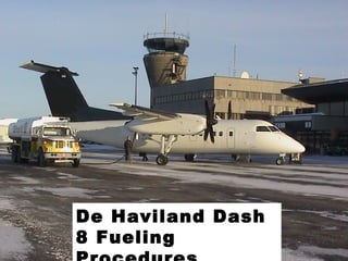
21. End of the De Haviland
Dash 8 Fueling Procedures
Presentation