1. Formula SAE Nose Cone
ME 483 Computational Fluid Dynamics Project
Yusheng Chen
In sake of increasing aero performances of the race
car, the nose cone is designed by fitting with the
chassis. Nose cone is made by Aluminum sheet.
Modeling is done by SolidWorks 2012.
Introduction
Geometry
The 2015 Formula SAE senior design team is working
on designing and fabricating the race car for FSAE
competition at Brooklyn, Michigan in May 2015. This
project is to help Formula SAE senior design team
analyze aerodynamic properties of nose cone by
simulating it under racing speed condition. The steps
to solve this problem included creating the geometry,
setting up boundary conditions, displaying results,
and demonstrating conclusion.
Boundary Condition
Once the geometry was the boundary condition was
successfully setup. The given values of boundary
conditions of air flow was shown in Table 1.
Analysis
Discussion
Figure 1. Nose Cone Figure 2. Nose Cone Assembled on Chassis
Temperature 𝟐𝟓℃
Inlet Velocity and Fluid Type
𝟐𝟕 𝐦/𝐬 Fully Turbulent
𝟏𝟓 𝐦/𝐬 Fully Turbulent
Density 1.185 𝐤𝐠/𝐦 𝟑
Viscosity 𝟏. 𝟖𝟑𝟏 × 𝟏𝟎−𝟓
𝐤𝐠/(𝐦 ∙ 𝐬)
Thermal Conductivity 𝟐. 𝟔𝟏 × 𝟏𝟎−𝟐
𝐖 /(𝐦 ∙ 𝐊)
Table 1. Boundary Condition of Air Flow
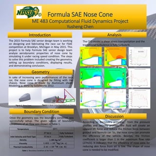
The CFD model is shear stress transportation and the
transitional turbulence is fully turbulent.
According to Bernoulli’s principle, from the pressure
profiles and velocity profiles, the fluid will create an
upward lift force and reduce the friction force between
ground and formula car. So, the nose cone can promote
the efficiency of the vehicle. Besides, the friction
coefficient is larger than 1 in the maximum flow rate
(27m/s). It indicates that the efficiency of nose cone for
reducing skin force from air is low. The shape of nose
cone is needed to be modified.