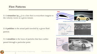
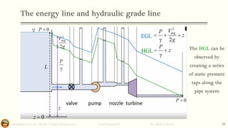
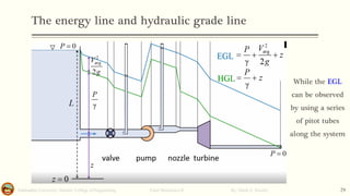
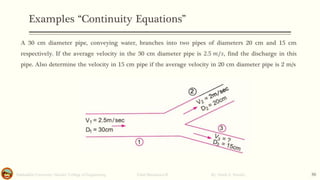
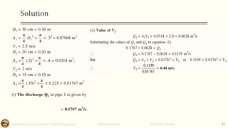
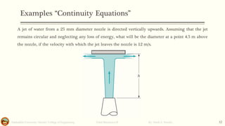
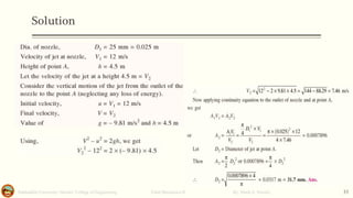
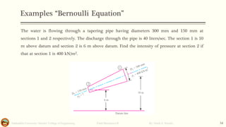
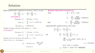
FLUID MECHANICS-II
CHAPTER-FOUR
Bernoulli Equation
University of Salahaddin- Hawler - College of Engineering
Chemical and Petrochemical Department
By: Hardi A. Siwaily
M.Sc. Mechanical Engineering- Thermal Power. Contact: hardi.m.rasul@su.edu.krd
LEARNING OUTCOMES
▪ Introduction
▪ Flow Patterns
▪ Physical interpretation of Bernoulli equation
▪ Bernoulli equation
▪ Apply The Bernoulli equation
Salahaddin University- Hawler/ College of Engineering. Fluid Mechanics-II By: Hardi A. Siwaily 1
Introduction
Salahaddin University- Hawler/ College of Engineering. Fluid Mechanics-II By: Hardi A. Siwaily 2
▪ Want to discuss the properties of a moving fluid.
▪ Will do this initially under the simplest possible conditions, leading to Bernoulli’s equation.
▪ The following restrictions apply.
• Flow is inviscid, there are no viscous drag forces
• Heat conduction is not possible for an inviscid flow
• The fluid is incompressible.
• The flow is steady (velocity pattern constant).
• The paths traveled by small sections of the fluid are well-defined.
• Will be implicitly using the Euler equations of motion.
Flow Patterns
Salahaddin University- Hawler/ College of Engineering. Fluid Mechanics-II By: Hardi A. Siwaily
3
1) A streamline (𝝋(𝒙,𝒕)): is a line that is everywhere tangent to
the velocity vector at a given instant.
2) A pathline: is the actual path traveled by a given fluid
particle.
3) A streakline is the locus of particles that have earlier
passed through a particular point.
Physical interpretation of Bernoulli equation
Salahaddin University- Hawler/ College of Engineering. Fluid Mechanics-II By: Hardi A. Siwaily 4
▪ Integration of the equation of motion to give the Bernoulli equation actually corresponds to the work-
energy principle often used in the study of dynamics.
▪ This principle results from a general integration of the equations of motion for an object in a very
similar to that done for the fluid particle. With certain assumptions, a statement of the work-energy
principle may be written as follows:
▪ The work done on a particle by all forces acting on the particle is equal to the change in the particle’s
kinetic energy.
▪ The Bernoulli equation is a mathematical statement of this principle.
▪ In fact, an alternate method of deriving the Bernoulli equation is to use the first and second laws of
thermodynamics (the energy and entropy equations), rather than Newton’s second law. With the
approach restrictions, the general energy equation reduces to the Bernoulli equation.
Salahaddin University- Hawler/ College of Engineering. Fluid Mechanics-II By: Hardi A. Siwaily 5
Bernoulli equation
▪ It describe the relationship between “Pressure”, “Velocity” and Elevation” of a flowing Fluid.
▪ It has countless applications.
Bernoulli equation
Salahaddin University- Hawler/ College of Engineering. Fluid Mechanics-II By: Hardi A. Siwaily 6
▪ The equation states that the sum of these three terms remains constant along a streamline.
▪ Each of the terms is a pressure:
• The first term is static pressure, which is just the pressure of the fluid.
• The second term is dynamic pressure, which is the function of density and velocity and
represents the fluid kinetic energy.
• And the last term is hydrostatic pressure, the pressure exerted by the fluid due to gravity.
Bernoulli equation Forms
Salahaddin University- Hawler/ College of Engineering. Fluid Mechanics-II By: Hardi A. Siwaily 7
Salahaddin University- Hawler/ College of Engineering. Fluid Mechanics-II By: Hardi A. Siwaily 8
Stream Line detail
▪ A curve that all points are tangent to the particle velocity vector.
Apply The Bernoulli equation
Salahaddin University- Hawler/ College of Engineering. Fluid Mechanics-II By: Hardi A. Siwaily 9
▪ Example of flow through a pipe that has changed in diameter.
▪ If the change in pressure height is not significant, between points 1 and 2, the potential energy term
cancel each other out
Apply The Bernoulli equation
Salahaddin University- Hawler/ College of Engineering. Fluid Mechanics-II By: Hardi A. Siwaily 10
▪ Now, If we assume the fluid is incompressible, The mass flow rate at points 1 and 2 must be equal.
▪ This gives what’s called a continuity equation
Which is equal to
Apply The Bernoulli equation
Salahaddin University- Hawler/ College of Engineering. Fluid Mechanics-II By: Hardi A. Siwaily 11
▪ Rearrange the continuity equation:
▪ Here, since the A2 < A1, which means that V2 > V1
▪ By substituting in the pressure change equation
▪ We can see that, since V2 > V1, then P2 < P1.
Apply The Bernoulli equation
Salahaddin University- Hawler/ College of Engineering. Fluid Mechanics-II By: Hardi A. Siwaily 12
▪ This concept, that for the horizontal flow increase in fluid velocity must be accompanied by decrease
in pressure
Apply The Bernoulli equation
Salahaddin University- Hawler/ College of Engineering. Fluid Mechanics-II By: Hardi A. Siwaily 13
▪ We can explain how plane wings generate lift by applying the Bernoulli Equation:
The stagnation point
Salahaddin University- Hawler/ College of Engineering. Fluid Mechanics-II By: Hardi A. Siwaily 14
When fluid flows around any stationary body, some of the streamlines pass over and some pass under the
object. But there is always a stagnation point where the stagnation streamlines terminate. The stagnation
pressure is
V : is the velocity at some point on streamline away from the
obstruction.
The total pressure is equal to the sum of static, dynamic and hydrostatic pressures, 𝑃𝑇
The pitot tube
Salahaddin University- Hawler/ College of Engineering. Fluid Mechanics-II By: Hardi A. Siwaily 15
Rearranging leads to
The free jet
Salahaddin University- Hawler/ College of Engineering. Fluid Mechanics-II By: Hardi A. Siwaily 16
The free jet result was first obtained in 1643 by Evangelista
Torricelli.
As a result 𝒗 = √𝟐𝒈𝒉 is the speed of
the freely falling body starting from rest.
The free jet
Salahaddin University- Hawler/ College of Engineering. Fluid Mechanics-II By: Hardi A. Siwaily 17
Horizontal nozzle, the velocity at center line v2 is slightly smaller
than v3 and slightly larger than v1.
For d ≪ h, OK to use v2 as the average velocity.
Streamlines cannot follow sharp corners exactly. Would take an
infinite pressure gradient to achieve zero radii of curvature
(i.e. R = 0 ). Uniform velocity only occurs at a-a line.
Vena Contracta effect. Jet diameter, dj is slightly smaller
than hole diameter dh.
The free jet
Salahaddin University- Hawler/ College of Engineering. Fluid Mechanics-II By: Hardi A. Siwaily 18
The contraction coefficient, 𝐶𝑑 = 𝐴𝑗/𝐴ℎ is the ratio of the jet area 𝐴𝑗, and hole area 𝐴ℎ.
Example:
Salahaddin University- Hawler/ College of Engineering. Fluid Mechanics-II By: Hardi A. Siwaily 19
As shown in the figure, a stream of water 𝑑 = 0.10 𝑚 flows steadily from a tank of diameter 𝐷
= 1.0 𝑚. What flow rate is needed from the inlet to maintain a constant water volume in the header
tank depth? The depth of water at the outlet is 2.0 𝑚.
Can regard outlet as a free jet (note water level at (1) is not going
down).
Flow rate measurement
Salahaddin University- Hawler/ College of Engineering. Fluid Mechanics-II By: Hardi A. Siwaily 20
One way to measure the flow rate is to place a constriction in a
pipe. The resulting change in velocity (the continuity equation),
leads to a pressure difference. The absolute fluid velocity can be
determined from the pressure difference between (1) and (2).
The Orifice, Nozzle, and Venturi meters analysis here ignores
viscous, compressibility, and other real-world effects.
Flow rate measurement
Salahaddin University- Hawler/ College of Engineering. Fluid Mechanics-II By: Hardi A. Siwaily 21
to determine the flow rate, need 𝑣2
The pressure differences give
the flow rate. Real-world flows
are 1% to 40% smaller.
Sluice gate flow rate
Salahaddin University- Hawler/ College of Engineering. Fluid Mechanics-II By: Hardi A. Siwaily 22
The height of water in the channel can be used to determine the flow rate of water out of the
reservoir.
Where b: is the width of the reservoir.
Example
Salahaddin University- Hawler/ College of Engineering. Fluid Mechanics-II By: Hardi A. Siwaily 23
The following figure shows the flow through a horizontal tube, determining the flow rate as a
function of the diameter of the tube.
Use the Venturi meter equation:
Sharp crested weir
Salahaddin University- Hawler/ College of Engineering. Fluid Mechanics-II By: Hardi A. Siwaily 24
The energy line and hydraulic grade line
Salahaddin University- Hawler/ College of Engineering. Fluid Mechanics-II By: Hardi A. Siwaily 25
The energy line and hydraulic grade line
Salahaddin University- Hawler/ College of Engineering. Fluid Mechanics-II By: Hardi A. Siwaily 26
The Energy Grade Line (EGL) and Hydraulic Grade Line (HGL) help visualize how
mechanical energy changes in flow.
𝐸𝐺𝐿 =
𝑃
𝛾
+
𝑉
𝑎𝑣𝑔
2
2𝑔
+ 𝑧
𝐻𝐺𝐿 =
𝑃
𝛾
+ 𝑧
𝐸𝐺𝐿 − 𝐻𝐺𝐿 =
𝑉
𝑎𝑣𝑔
2
2𝑔
Represents the total mechanical energy in the
flow
Represents the total potential energy in the flow
Represents the total kinetic energy in the flow
The energy line and hydraulic grade line
Salahaddin University- Hawler/ College of Engineering. Fluid Mechanics-II By: Hardi A. Siwaily 27
L: Distance of water level
from Ground level
For Big Reservoir means:
∆L/ ∆t is constant, v=0 and
P=0
𝐸𝐺𝐿 = 𝑧
𝐻𝐺𝐿 = 𝑧
Since fluid travels through
the sharped edge, it will
face frictional and velocity
loss
In the section of pipe, the
friction also decreases
due to pipe wall friction
Then, both EGL and
HGL drop rapidly
through the valve
Again, both will decrease
due to pipe friction
Pump boost the pressure
both EGL and HGL will
increase
After the pump, the EGL
and HGL decrease due to
pipe friction
Then, the fluid travels
through the nozzle,
nozzles accelerate flow
and decrease pressure
Then through the nozzle
pipe also both will drop
Turbine extract
mechanical energy from
the fluid, so EGL and
HGL decrease sharply
Then both EGL and HGL
decrease due to pipe
friction loss
The energy line and hydraulic grade line
Salahaddin University- Hawler/ College of Engineering. Fluid Mechanics-II By: Hardi A. Siwaily 28
The HGL can be
observed by
creating a series
of static pressure
taps along the
pipe system
The energy line and hydraulic grade line
Salahaddin University- Hawler/ College of Engineering. Fluid Mechanics-II By: Hardi A. Siwaily 29
While the EGL
can be observed
by using a series
of pitot tubes
along the system
Examples “Continuity Equations”
Salahaddin University- Hawler/ College of Engineering. Fluid Mechanics-II By: Hardi A. Siwaily 30
A 30 cm diameter pipe, conveying water, branches into two pipes of diameters 20 cm and 15 cm
respectively. If the average velocity in the 30 cm diameter pipe is 2.5 𝑚/𝑠, find the discharge in this
pipe. Also determine the velocity in 15 cm pipe if the average velocity in 20 cm diameter pipe is 2 m/s
Solution
Salahaddin University- Hawler/ College of Engineering. Fluid Mechanics-II By: Hardi A. Siwaily 31
Examples “Continuity Equations”
Salahaddin University- Hawler/ College of Engineering. Fluid Mechanics-II By: Hardi A. Siwaily 32
A jet of water from a 25 mm diameter nozzle is directed vertically upwards. Assuming that the jet
remains circular and neglecting any loss of energy, what will be the diameter at a point 4.5 m above
the nozzle, if the velocity with which the jet leaves the nozzle is 12 m/s.
Solution
Salahaddin University- Hawler/ College of Engineering. Fluid Mechanics-II By: Hardi A. Siwaily 33
Examples “Bernoulli Equation”
Salahaddin University- Hawler/ College of Engineering. Fluid Mechanics-II By: Hardi A. Siwaily 34
The water is flowing through a tapering pipe having diameters 300 mm and 150 mm at
sections 1 and 2 respectively. The discharge through the pipe is 40 liters/sec. The section 1 is 10
m above datum and section 2 is 6 m above datum. Find the intensity of pressure at section 2 if
that at section 1 is 400 kN/m2.
Solution
Salahaddin University- Hawler/ College of Engineering. Fluid Mechanics-II By: Hardi A. Siwaily 35
Examples “Bernoulli Equation”
Salahaddin University- Hawler/ College of Engineering. Fluid Mechanics-II By: Hardi A. Siwaily 36
Gasoline (sp. gr. 0.8) is flowing upwards a vertical pipeline which tapers from 300 mm to 150 mm
diameter. A gasoline mercury differential manometer is connected between 300 mm and 150 mm pipe
section to measure the rate of flow. The distance between the manometer tappings is 1 meter and gauge
reading is 500 mm of mercury. Find:
(i) Differential gauge reading in terms of gasoline head;
(ii) Rate of flow.
Neglect friction and other losses between tappings.
Solution
Salahaddin University- Hawler/ College of Engineering. Fluid Mechanics-II By: Hardi A. Siwaily 37
𝑫𝒊𝒇𝒇𝒆𝒓𝒆𝒏𝒄𝒊𝒂𝒍 𝒈𝒖𝒂𝒈𝒆 𝒓𝒆𝒂𝒅𝒊𝒏𝒈 𝒊𝒏 𝒕𝒆𝒓𝒎 𝒐𝒇 𝑮𝒂𝒔𝒐𝒍𝒊𝒏𝒆 𝑯𝒆𝒂𝒅
=
𝑺𝒑.𝑮𝒓𝒂𝒗𝒊𝒕𝒚 𝑴𝒆𝒓𝒄𝒖𝒕𝒚 −𝑺𝒑.𝑮𝒓𝒂𝒗𝒊𝒕𝒚 𝑮𝒂𝒔.
𝑺𝒑.𝑮𝒓𝒂𝒗𝒊𝒕𝒚 𝑮𝒂𝒔.
× 𝑮𝒖𝒂𝒈𝒆 𝑹𝒆𝒂𝒅𝒊𝒏𝒈
=
13.9 − 0.8
0.8
× 0.5 = 8 𝑚 𝑜𝑓 𝑔𝑎𝑠𝑜𝑙𝑖𝑛𝑒
End of lecture

Fluid mechanics for engineering students

  • 1.
    FLUID MECHANICS-II CHAPTER-FOUR Bernoulli Equation Universityof Salahaddin- Hawler - College of Engineering Chemical and Petrochemical Department By: Hardi A. Siwaily M.Sc. Mechanical Engineering- Thermal Power. Contact: hardi.m.rasul@su.edu.krd
  • 2.
    LEARNING OUTCOMES ▪ Introduction ▪Flow Patterns ▪ Physical interpretation of Bernoulli equation ▪ Bernoulli equation ▪ Apply The Bernoulli equation Salahaddin University- Hawler/ College of Engineering. Fluid Mechanics-II By: Hardi A. Siwaily 1
  • 3.
    Introduction Salahaddin University- Hawler/College of Engineering. Fluid Mechanics-II By: Hardi A. Siwaily 2 ▪ Want to discuss the properties of a moving fluid. ▪ Will do this initially under the simplest possible conditions, leading to Bernoulli’s equation. ▪ The following restrictions apply. • Flow is inviscid, there are no viscous drag forces • Heat conduction is not possible for an inviscid flow • The fluid is incompressible. • The flow is steady (velocity pattern constant). • The paths traveled by small sections of the fluid are well-defined. • Will be implicitly using the Euler equations of motion.
  • 4.
    Flow Patterns Salahaddin University-Hawler/ College of Engineering. Fluid Mechanics-II By: Hardi A. Siwaily 3 1) A streamline (𝝋(𝒙,𝒕)): is a line that is everywhere tangent to the velocity vector at a given instant. 2) A pathline: is the actual path traveled by a given fluid particle. 3) A streakline is the locus of particles that have earlier passed through a particular point.
  • 5.
    Physical interpretation ofBernoulli equation Salahaddin University- Hawler/ College of Engineering. Fluid Mechanics-II By: Hardi A. Siwaily 4 ▪ Integration of the equation of motion to give the Bernoulli equation actually corresponds to the work- energy principle often used in the study of dynamics. ▪ This principle results from a general integration of the equations of motion for an object in a very similar to that done for the fluid particle. With certain assumptions, a statement of the work-energy principle may be written as follows: ▪ The work done on a particle by all forces acting on the particle is equal to the change in the particle’s kinetic energy. ▪ The Bernoulli equation is a mathematical statement of this principle. ▪ In fact, an alternate method of deriving the Bernoulli equation is to use the first and second laws of thermodynamics (the energy and entropy equations), rather than Newton’s second law. With the approach restrictions, the general energy equation reduces to the Bernoulli equation.
  • 6.
    Salahaddin University- Hawler/College of Engineering. Fluid Mechanics-II By: Hardi A. Siwaily 5 Bernoulli equation ▪ It describe the relationship between “Pressure”, “Velocity” and Elevation” of a flowing Fluid. ▪ It has countless applications.
  • 7.
    Bernoulli equation Salahaddin University-Hawler/ College of Engineering. Fluid Mechanics-II By: Hardi A. Siwaily 6 ▪ The equation states that the sum of these three terms remains constant along a streamline. ▪ Each of the terms is a pressure: • The first term is static pressure, which is just the pressure of the fluid. • The second term is dynamic pressure, which is the function of density and velocity and represents the fluid kinetic energy. • And the last term is hydrostatic pressure, the pressure exerted by the fluid due to gravity.
  • 8.
    Bernoulli equation Forms SalahaddinUniversity- Hawler/ College of Engineering. Fluid Mechanics-II By: Hardi A. Siwaily 7
  • 9.
    Salahaddin University- Hawler/College of Engineering. Fluid Mechanics-II By: Hardi A. Siwaily 8 Stream Line detail ▪ A curve that all points are tangent to the particle velocity vector.
  • 10.
    Apply The Bernoulliequation Salahaddin University- Hawler/ College of Engineering. Fluid Mechanics-II By: Hardi A. Siwaily 9 ▪ Example of flow through a pipe that has changed in diameter. ▪ If the change in pressure height is not significant, between points 1 and 2, the potential energy term cancel each other out
  • 11.
    Apply The Bernoulliequation Salahaddin University- Hawler/ College of Engineering. Fluid Mechanics-II By: Hardi A. Siwaily 10 ▪ Now, If we assume the fluid is incompressible, The mass flow rate at points 1 and 2 must be equal. ▪ This gives what’s called a continuity equation Which is equal to
  • 12.
    Apply The Bernoulliequation Salahaddin University- Hawler/ College of Engineering. Fluid Mechanics-II By: Hardi A. Siwaily 11 ▪ Rearrange the continuity equation: ▪ Here, since the A2 < A1, which means that V2 > V1 ▪ By substituting in the pressure change equation ▪ We can see that, since V2 > V1, then P2 < P1.
  • 13.
    Apply The Bernoulliequation Salahaddin University- Hawler/ College of Engineering. Fluid Mechanics-II By: Hardi A. Siwaily 12 ▪ This concept, that for the horizontal flow increase in fluid velocity must be accompanied by decrease in pressure
  • 14.
    Apply The Bernoulliequation Salahaddin University- Hawler/ College of Engineering. Fluid Mechanics-II By: Hardi A. Siwaily 13 ▪ We can explain how plane wings generate lift by applying the Bernoulli Equation:
  • 15.
    The stagnation point SalahaddinUniversity- Hawler/ College of Engineering. Fluid Mechanics-II By: Hardi A. Siwaily 14 When fluid flows around any stationary body, some of the streamlines pass over and some pass under the object. But there is always a stagnation point where the stagnation streamlines terminate. The stagnation pressure is V : is the velocity at some point on streamline away from the obstruction. The total pressure is equal to the sum of static, dynamic and hydrostatic pressures, 𝑃𝑇
  • 16.
    The pitot tube SalahaddinUniversity- Hawler/ College of Engineering. Fluid Mechanics-II By: Hardi A. Siwaily 15 Rearranging leads to
  • 17.
    The free jet SalahaddinUniversity- Hawler/ College of Engineering. Fluid Mechanics-II By: Hardi A. Siwaily 16 The free jet result was first obtained in 1643 by Evangelista Torricelli. As a result 𝒗 = √𝟐𝒈𝒉 is the speed of the freely falling body starting from rest.
  • 18.
    The free jet SalahaddinUniversity- Hawler/ College of Engineering. Fluid Mechanics-II By: Hardi A. Siwaily 17 Horizontal nozzle, the velocity at center line v2 is slightly smaller than v3 and slightly larger than v1. For d ≪ h, OK to use v2 as the average velocity. Streamlines cannot follow sharp corners exactly. Would take an infinite pressure gradient to achieve zero radii of curvature (i.e. R = 0 ). Uniform velocity only occurs at a-a line. Vena Contracta effect. Jet diameter, dj is slightly smaller than hole diameter dh.
  • 19.
    The free jet SalahaddinUniversity- Hawler/ College of Engineering. Fluid Mechanics-II By: Hardi A. Siwaily 18 The contraction coefficient, 𝐶𝑑 = 𝐴𝑗/𝐴ℎ is the ratio of the jet area 𝐴𝑗, and hole area 𝐴ℎ.
  • 20.
    Example: Salahaddin University- Hawler/College of Engineering. Fluid Mechanics-II By: Hardi A. Siwaily 19 As shown in the figure, a stream of water 𝑑 = 0.10 𝑚 flows steadily from a tank of diameter 𝐷 = 1.0 𝑚. What flow rate is needed from the inlet to maintain a constant water volume in the header tank depth? The depth of water at the outlet is 2.0 𝑚. Can regard outlet as a free jet (note water level at (1) is not going down).
  • 21.
    Flow rate measurement SalahaddinUniversity- Hawler/ College of Engineering. Fluid Mechanics-II By: Hardi A. Siwaily 20 One way to measure the flow rate is to place a constriction in a pipe. The resulting change in velocity (the continuity equation), leads to a pressure difference. The absolute fluid velocity can be determined from the pressure difference between (1) and (2). The Orifice, Nozzle, and Venturi meters analysis here ignores viscous, compressibility, and other real-world effects.
  • 22.
    Flow rate measurement SalahaddinUniversity- Hawler/ College of Engineering. Fluid Mechanics-II By: Hardi A. Siwaily 21 to determine the flow rate, need 𝑣2 The pressure differences give the flow rate. Real-world flows are 1% to 40% smaller.
  • 23.
    Sluice gate flowrate Salahaddin University- Hawler/ College of Engineering. Fluid Mechanics-II By: Hardi A. Siwaily 22 The height of water in the channel can be used to determine the flow rate of water out of the reservoir. Where b: is the width of the reservoir.
  • 24.
    Example Salahaddin University- Hawler/College of Engineering. Fluid Mechanics-II By: Hardi A. Siwaily 23 The following figure shows the flow through a horizontal tube, determining the flow rate as a function of the diameter of the tube. Use the Venturi meter equation:
  • 25.
    Sharp crested weir SalahaddinUniversity- Hawler/ College of Engineering. Fluid Mechanics-II By: Hardi A. Siwaily 24
  • 26.
    The energy lineand hydraulic grade line Salahaddin University- Hawler/ College of Engineering. Fluid Mechanics-II By: Hardi A. Siwaily 25
  • 27.
    The energy lineand hydraulic grade line Salahaddin University- Hawler/ College of Engineering. Fluid Mechanics-II By: Hardi A. Siwaily 26 The Energy Grade Line (EGL) and Hydraulic Grade Line (HGL) help visualize how mechanical energy changes in flow. 𝐸𝐺𝐿 = 𝑃 𝛾 + 𝑉 𝑎𝑣𝑔 2 2𝑔 + 𝑧 𝐻𝐺𝐿 = 𝑃 𝛾 + 𝑧 𝐸𝐺𝐿 − 𝐻𝐺𝐿 = 𝑉 𝑎𝑣𝑔 2 2𝑔 Represents the total mechanical energy in the flow Represents the total potential energy in the flow Represents the total kinetic energy in the flow
  • 28.
    The energy lineand hydraulic grade line Salahaddin University- Hawler/ College of Engineering. Fluid Mechanics-II By: Hardi A. Siwaily 27 L: Distance of water level from Ground level For Big Reservoir means: ∆L/ ∆t is constant, v=0 and P=0 𝐸𝐺𝐿 = 𝑧 𝐻𝐺𝐿 = 𝑧 Since fluid travels through the sharped edge, it will face frictional and velocity loss In the section of pipe, the friction also decreases due to pipe wall friction Then, both EGL and HGL drop rapidly through the valve Again, both will decrease due to pipe friction Pump boost the pressure both EGL and HGL will increase After the pump, the EGL and HGL decrease due to pipe friction Then, the fluid travels through the nozzle, nozzles accelerate flow and decrease pressure Then through the nozzle pipe also both will drop Turbine extract mechanical energy from the fluid, so EGL and HGL decrease sharply Then both EGL and HGL decrease due to pipe friction loss
  • 29.
    The energy lineand hydraulic grade line Salahaddin University- Hawler/ College of Engineering. Fluid Mechanics-II By: Hardi A. Siwaily 28 The HGL can be observed by creating a series of static pressure taps along the pipe system
  • 30.
    The energy lineand hydraulic grade line Salahaddin University- Hawler/ College of Engineering. Fluid Mechanics-II By: Hardi A. Siwaily 29 While the EGL can be observed by using a series of pitot tubes along the system
  • 31.
    Examples “Continuity Equations” SalahaddinUniversity- Hawler/ College of Engineering. Fluid Mechanics-II By: Hardi A. Siwaily 30 A 30 cm diameter pipe, conveying water, branches into two pipes of diameters 20 cm and 15 cm respectively. If the average velocity in the 30 cm diameter pipe is 2.5 𝑚/𝑠, find the discharge in this pipe. Also determine the velocity in 15 cm pipe if the average velocity in 20 cm diameter pipe is 2 m/s
  • 32.
    Solution Salahaddin University- Hawler/College of Engineering. Fluid Mechanics-II By: Hardi A. Siwaily 31
  • 33.
    Examples “Continuity Equations” SalahaddinUniversity- Hawler/ College of Engineering. Fluid Mechanics-II By: Hardi A. Siwaily 32 A jet of water from a 25 mm diameter nozzle is directed vertically upwards. Assuming that the jet remains circular and neglecting any loss of energy, what will be the diameter at a point 4.5 m above the nozzle, if the velocity with which the jet leaves the nozzle is 12 m/s.
  • 34.
    Solution Salahaddin University- Hawler/College of Engineering. Fluid Mechanics-II By: Hardi A. Siwaily 33
  • 35.
    Examples “Bernoulli Equation” SalahaddinUniversity- Hawler/ College of Engineering. Fluid Mechanics-II By: Hardi A. Siwaily 34 The water is flowing through a tapering pipe having diameters 300 mm and 150 mm at sections 1 and 2 respectively. The discharge through the pipe is 40 liters/sec. The section 1 is 10 m above datum and section 2 is 6 m above datum. Find the intensity of pressure at section 2 if that at section 1 is 400 kN/m2.
  • 36.
    Solution Salahaddin University- Hawler/College of Engineering. Fluid Mechanics-II By: Hardi A. Siwaily 35
  • 37.
    Examples “Bernoulli Equation” SalahaddinUniversity- Hawler/ College of Engineering. Fluid Mechanics-II By: Hardi A. Siwaily 36 Gasoline (sp. gr. 0.8) is flowing upwards a vertical pipeline which tapers from 300 mm to 150 mm diameter. A gasoline mercury differential manometer is connected between 300 mm and 150 mm pipe section to measure the rate of flow. The distance between the manometer tappings is 1 meter and gauge reading is 500 mm of mercury. Find: (i) Differential gauge reading in terms of gasoline head; (ii) Rate of flow. Neglect friction and other losses between tappings.
  • 38.
    Solution Salahaddin University- Hawler/College of Engineering. Fluid Mechanics-II By: Hardi A. Siwaily 37 𝑫𝒊𝒇𝒇𝒆𝒓𝒆𝒏𝒄𝒊𝒂𝒍 𝒈𝒖𝒂𝒈𝒆 𝒓𝒆𝒂𝒅𝒊𝒏𝒈 𝒊𝒏 𝒕𝒆𝒓𝒎 𝒐𝒇 𝑮𝒂𝒔𝒐𝒍𝒊𝒏𝒆 𝑯𝒆𝒂𝒅 = 𝑺𝒑.𝑮𝒓𝒂𝒗𝒊𝒕𝒚 𝑴𝒆𝒓𝒄𝒖𝒕𝒚 −𝑺𝒑.𝑮𝒓𝒂𝒗𝒊𝒕𝒚 𝑮𝒂𝒔. 𝑺𝒑.𝑮𝒓𝒂𝒗𝒊𝒕𝒚 𝑮𝒂𝒔. × 𝑮𝒖𝒂𝒈𝒆 𝑹𝒆𝒂𝒅𝒊𝒏𝒈 = 13.9 − 0.8 0.8 × 0.5 = 8 𝑚 𝑜𝑓 𝑔𝑎𝑠𝑜𝑙𝑖𝑛𝑒
  • 39.