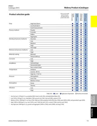
Download to read offline


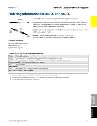
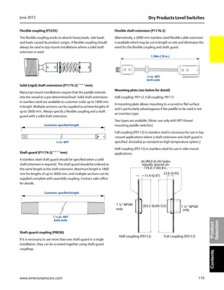
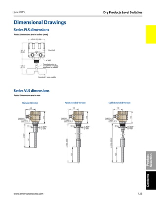
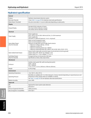
![162
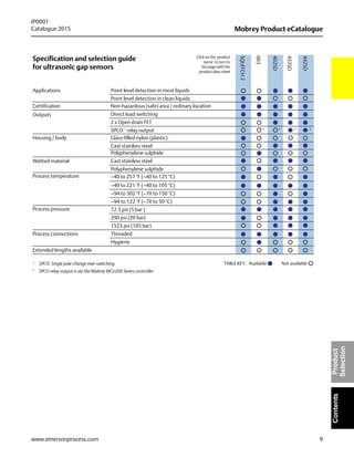
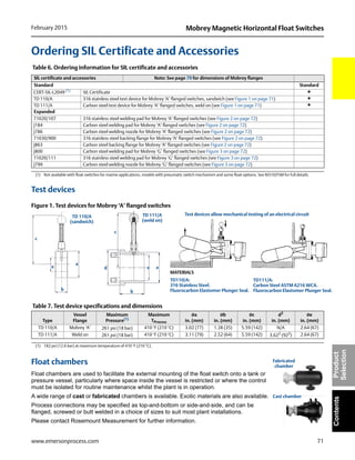
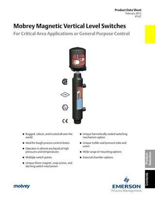
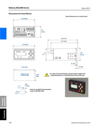
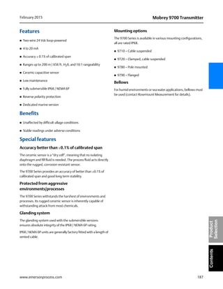
Mobrey MCU900 Series March 2015
www.emersonprocess.com
Product
SelectionContents
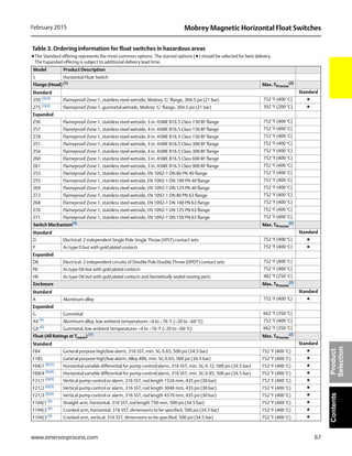
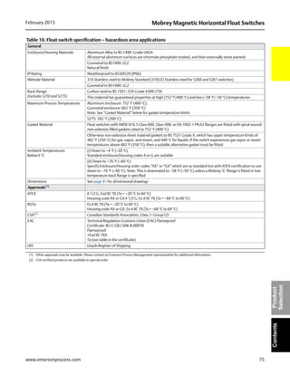
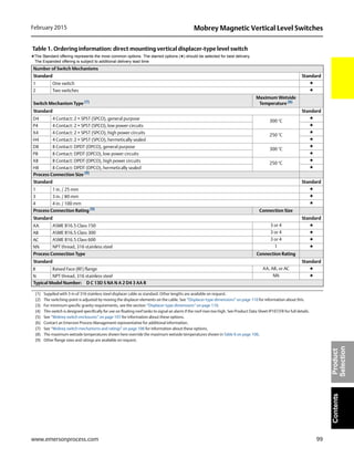
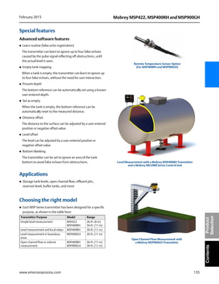
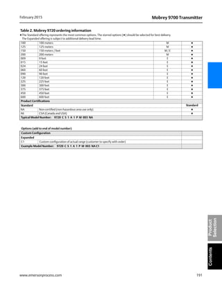
Environment
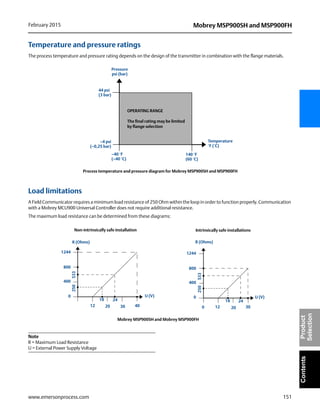
Ambient temperature
–40 to 55 °C (–40 to 131 °F)
See Product Certifications for approval temperatures ranges
Relative humidity
Wall mount: 100%
Panel mount: 90% non-condensing
Electrical safety
EN61010-1
Ingress Protection (IP) rating
IP-rated wall mount: IP65 indoor/outdoor
Panel mount:
IP40 indoor mount (or IP65 if with optional hood)
Vibration
Control Room: 0.1 to 9 Hz 1.5 mm displacement peak
amplitude / 9 to 200 Hz 0.5 g
Installation category
III : Supply voltage < 127Vac (IEC60664)
II : Supply voltage < 254Vac (IEC60664)
Pollution degree
2 (IEC60664)
Maximum altitude
2000 m
Electromagnetic Compatibility
Emissions and Immunity
(for IP-rated wall mount and panel mount):
EN61326-1:2006
Certifications
CE-mark and ATEX
Product Certifications
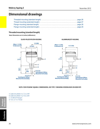
Note
The MCU900 Series is mounted in a non-hazardous area, and
provides a protected (intrinsically safe) 24 volts direct current
supply to a transmitter in a hazardous area.
European directive information
The EC declaration of conformity for all applicable European
directives for this product may be obtained by contacting
your local sales office.
ATEX Directive (94/9/EC)
Complies with the ATEX Directive
Low Voltage Directive (2006/95/EC)
EN61010 Part 1: 2001
Pressure equipment directive (PED) (97/23/EC)
The MCU900 Series is outside the scope of the PED directive
Electro magnetic compatibility (EMC) directive
EN61326-1: 2006
CE-mark
The Mobrey MCU900 Series complies with EMC, ATEX, and
LVD directives
Restriction of Hazardous Substances (ROHS)
The Mobrey MCU900 Series is exempt
Hazardous locations certifications
ATEX intrinsically safe approval
Certificate numbers:
BAS00ATEX7064 (Wall Mount),
BAS01ATEX7225X (Panel Mount)
Intrinsically safe for II(1) G D,
[Ex ia Ga] IIC, [Ex ia Da] IIIC
Ambient temperature: –40 °C to +55 °C
Uo = 27,3 V, lo = 96,9 mA, Po = 0,66 W, Li = 0,22 mH, Ci = 0,6 nF
Special conditions for safe use
(Certificate BAS01ATEX7225X):
1. Terminal 30 must be earthed in the safe area to a high
integrity earth.](https://image.slidesharecdn.com/data-sheets-mobrey-product-ecatalogue-2015-edition-en-67194-180711073127/85/Float-Level-Switches-Measurement-Instruments-By-Raman-Instruments-Pvt-Ltd-164-320.jpg)

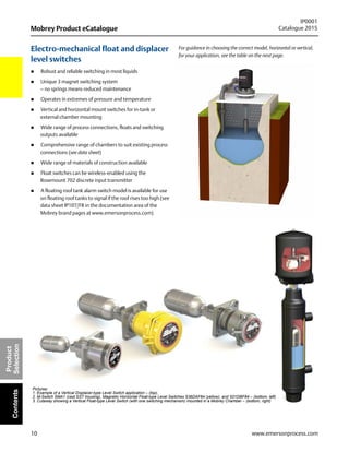
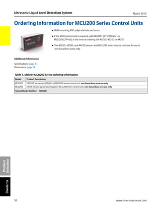
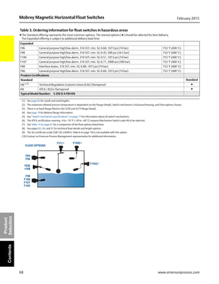
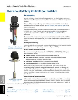
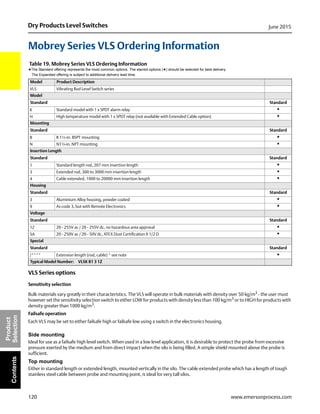
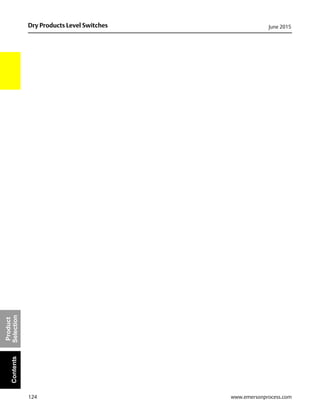
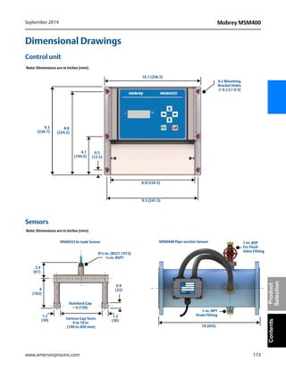
![172
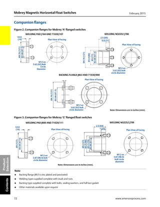
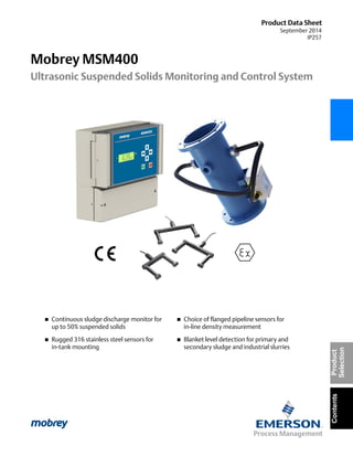
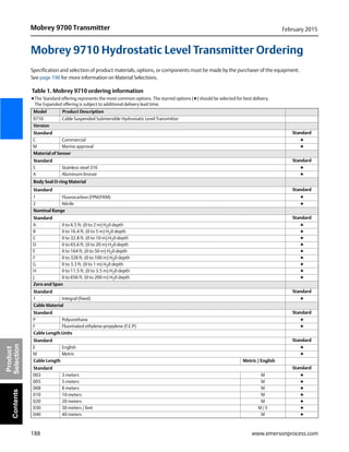
Mobrey MSM400 September 2014
www.emersonprocess.com
Product
SelectionContents
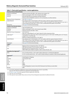
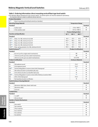
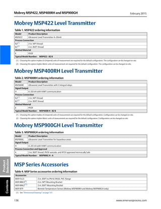
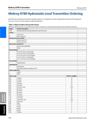
Product Certifications
Approved manufacturing location
Rosemount Measurement Limited
Slough, United Kingdom
European directive information
The EC declaration of conformity for all applicable European
directives for this product can be obtained by contacting your
local sales office.
ATEX directive (94/09/EC)
The control unit and gap sensors comply with EN60079-0
and EN60079-11
Low voltage directive (2006/95/EC)
The control unit complies with EN61010-1
The gap sensors are outside the scope of the LVD directive
Pressure equipment directive (PED) (97/23/EC)
The control unit and in-tank mounted gap sensor are outside
the scope of the PED Directive
The pipe-section gap sensor complies with the PED directive
Electro magnetic compatibility (EMC) directive
(2004/108/EC)
The control unit and sensors comply with EN 61326-1
CE-mark
The control unit and sensors comply with the applicable
directives
Hazardous location certifications
The MSM400 control unit (“control unit”) may be connected to
an intrinsically safe gap sensor located in a hazardous area.
The control unit must not itself be located in a hazardous area.
Control unit approvals
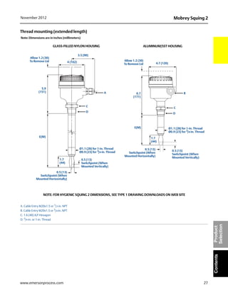
ATEX intrinsically safe approval (gap sensor inputs only)
Certificate numbers: ITS00ATEX2002X
Intrinsically safe for II (1) G, (Ga) [Ex ia] IIC
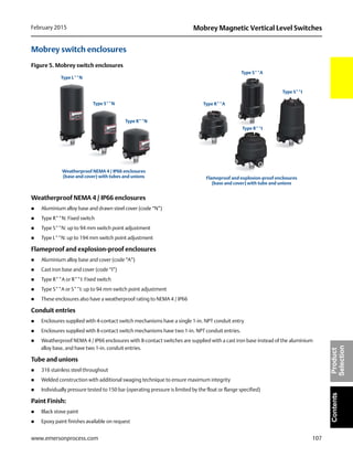
Ambient temperature: –40 to +55 °C
Channel 1 (Rx) electrical parameters:
Uo = 1.2 V, lo = 42.1 mA, Po = 13 mW, Co = 0.4 nF,
Lo = 0.04 mH
Channel 2 (Tx) electrical parameters:
Uo = 4.6 V, lo = 162 mA, Po = 0.2 W, Co = 0.4 nF,
Lo = 0.04 mH
IECEx intrinsically safe approval (gap sensor inputs only)
Certificate numbers: IECEx ITS 13.0044X
Intrinsically safe for (Ga) [Ex ia] IIC
Ambient temperature: –40 to +55 °C
Channel 1 (Rx) electrical parameters:
Uo = 1.2 V, lo = 42.1 mA, Po = 13 mW, Co = 0.4 nF,
Lo = 0.04 mH
Channel 2 (Tx) electrical parameters:
Uo = 4.6 V, lo = 162 mA, Po = 0.2 W, Co = 0.4 nF,
Lo = 0.04 mH
Gap sensor approvals
ATEX intrinsically safe approval
A Certificate numbers: ITS00ATEX2003X
Intrinsically safe for II 1 G, Ex ia IIC T6...T3 Ga
Ambient temperature: –40 to +70 °C
Electrical parameters:
Ui = 4.6 V, li = 162 mA, Pi = 0.2 W, Ci = 14 nF, Li = 0.1 mH
IECEx intrinsically safe approval
A Certificate numbers: IECEx ITS 13.0044X
Intrinsically safe for Ex ia IIC T6...T3 Ga
Ambient temperature: –40 to +70 °C
Electrical parameters:
Ui = 4.6 V, li = 162 mA, Pi = 0.2 W, Ci = 14 nF, Li = 0.1 mH](https://image.slidesharecdn.com/data-sheets-mobrey-product-ecatalogue-2015-edition-en-67194-180711073127/85/Float-Level-Switches-Measurement-Instruments-By-Raman-Instruments-Pvt-Ltd-174-320.jpg)

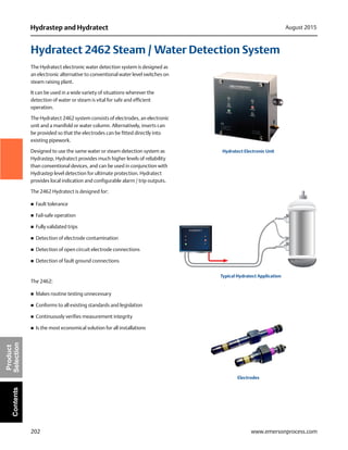
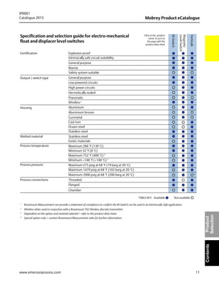
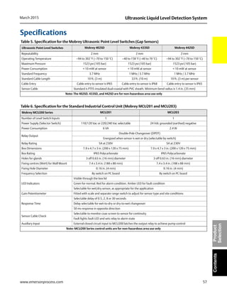
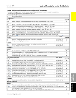
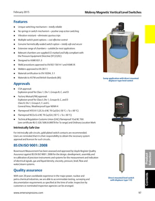
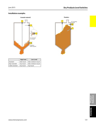
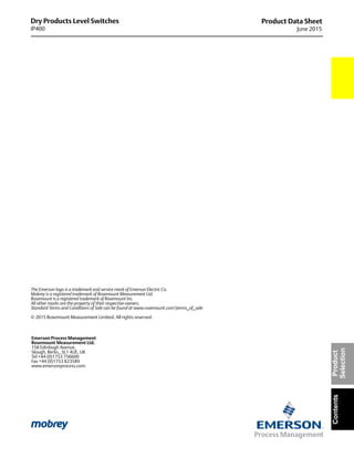
![207
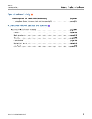
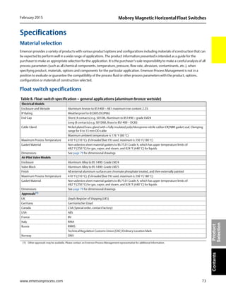
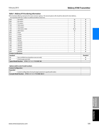
Hydrastep and HydratectAugust 2015
www.emersonprocess.com
ContentsProduct
Selection
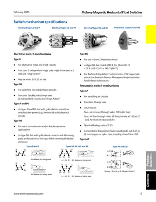
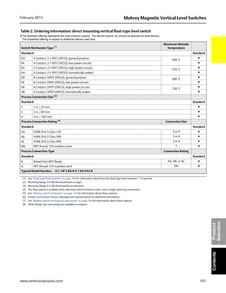
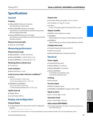
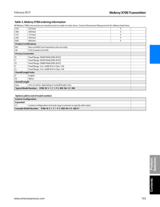
Mechanical
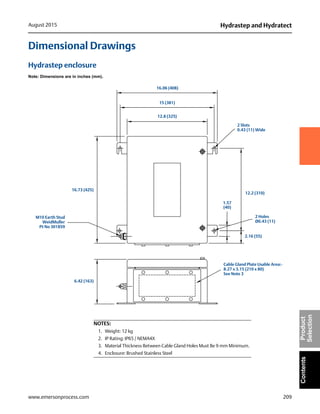
Weight 26.4 Ib (12 kg)
Control Unit Enclosure
Brushed stainless steel, wall mounting (four point), IP65 / NEMA4X
16.7 in. high x 12.8 in. wide x 6.4 in. deep (425 mm x 325 mm x 163 mm)
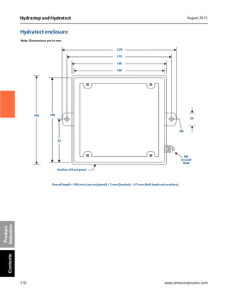
Remote Display Unit Enclosure
2468 3BB (Case style: DIN Panel Mount)
Dimensions: 5.67 in. x 2.38 in. x 7.87 in. deep (144 mm x 72 mm x 200mm)
Panel cutout: 5.41 in. x 2.60 in. (137.5mm x 66mm)
2468 3C (Case style: Large Panel Mount)
Dimensions: 7.56 in. x 3.78 in. x 8.23 in. deep (192mm x 96mm x 209mm)
Panel cutout: 7.32 in. x 3.62 in. (186mm x 92mm)
2468 3D (Case style: Rugged enclosure, NEMA 4X (IP65))
Dimensions: 11.89 in. x 7.32 in. x 6.89 in. deep (302mm x 186mm x 175mm)
Approvals
ATEX II3 G EEx nA IIC, T4 (–20 °C < ta < +70 °C)
CSA
(Canada) Ex nA [nL] nL IIC T4, (USA) CIass 1 Zone 2, AEx nA IIC
with relay output connected only to energy limited circuits
FM Approved for boiler water-level control
LVD EN 61010-1
Pressure Equipment Directive Safety accessory
Electromagnetic Compatibility EN 61326-1
(1) Dual power supply version of Hydrastep Control Unit – Table 1 on page 203 for option codes.
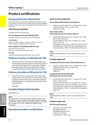
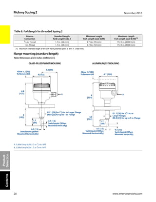
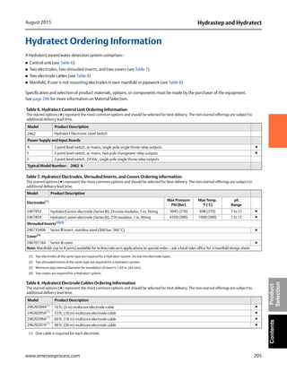
Table 9. Water Column Specifications
Parameter LP Rectangular Section HP Series 3 HP Super 3
Design Pressure 1740 psi (120 bar) 3045 psi (210 bar) 4350 psi (300 bar)
Test Pressure 2610 psi (180 bar) 4567 psi (315 bar) 6525 psi (450 bar)
Design Temp. 650 °F (343 °C) 698 °F (370 °C) 1040 °F (560 °C)
Design Code(1)
ASME B31.1 Power Piping ASME B31.1 Power Piping ASME B31.1 Power Piping
Maximum Length 138 in. (3500 mm) 138 in. (3500 mm) 138 in. (3500 mm)
Materials of
Construction(2) Carbon Steel ASTM A105/A106 GR B
Carbon Steel ASTM A105/A106 GR B body
with SA 479 – 316N electrode mounts
Stainless steel ASTM A312/A182 F316
with SA 479 – 316N electrode mounts
Protective Covers 18 SWG (17 AWG) Stainless steel 18 SWG (17 AWG) Stainless steel 18 SWG (17 AWG) Stainless steel
Gross Weight(3) 26.5 Ib (12 kg) 37.5 Ib (17 kg) 37.5 Ib (17 kg)
Electrode Types 459600602 or 459600802 246781ZA or 246782AC 246785A
Blanking Plugs(4)
24569A 450600880 24673763A
(1) Manufactured and tested in accordance with ASME Boiler and Pressure Vessel Code: Section 1.
(2) Material certification: in accordance with BS EN10204 3.1 (we can also provide to BS EN10204 3.2 at additional cost and if specified by Customer, prior to order).
(3) Typical for (610 mm / 24 in.) steam/water range, 12 port, with electrodes and covers.
(4) Electrode port blanking plugs are available to order using the part numbers given in each column.](https://image.slidesharecdn.com/data-sheets-mobrey-product-ecatalogue-2015-edition-en-67194-180711073127/85/Float-Level-Switches-Measurement-Instruments-By-Raman-Instruments-Pvt-Ltd-209-320.jpg)


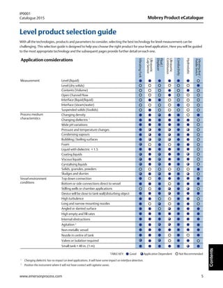
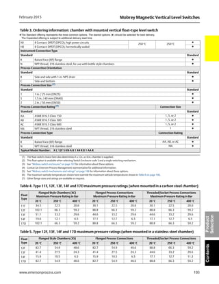
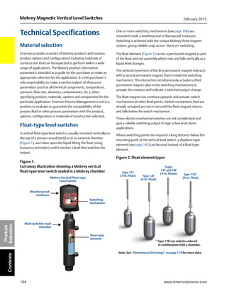
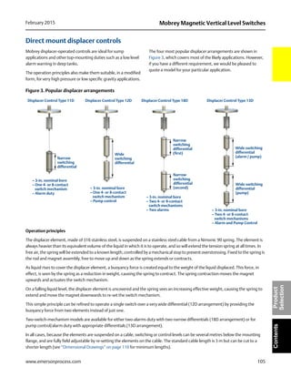
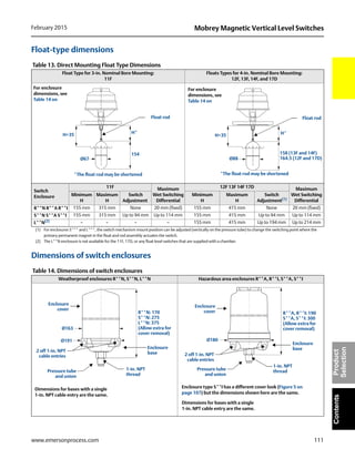
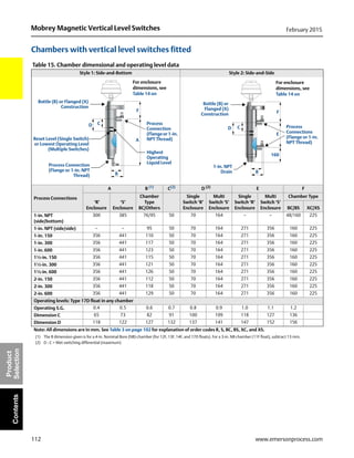
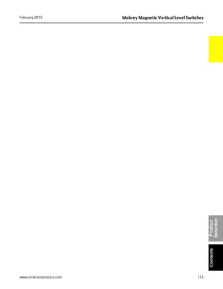
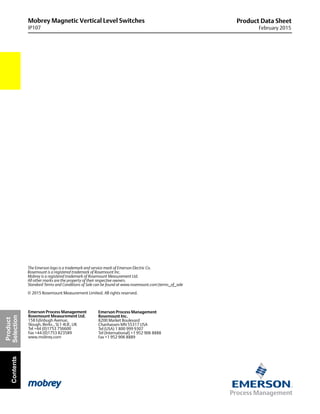
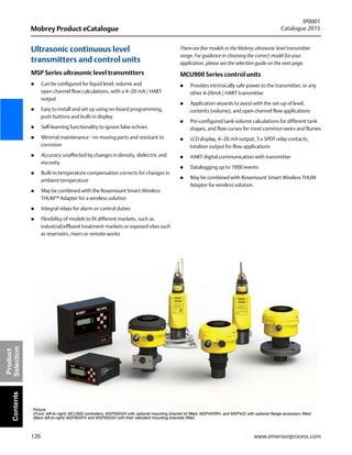
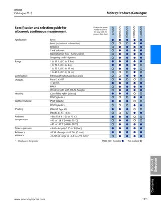
The 2015 Mobrey product catalogue introduces a range of process instrumentation solutions for liquid, gas, and dry ingredient measurement, emphasizing reliability and safety in various industries. It features standard and expanded product offerings with specific data sheets for level switches, continuous measurement, and conductivity monitoring, all designed to enhance efficiency and regulatory compliance. The catalogue also includes a product selection guide to assist customers in choosing the appropriate technology for their applications.


