Downloaded 40 times


The document contains figures from the textbook "Digital Systems: Principles and Applications, 10th Edition" relating to digital logic circuits such as latches, flip-flops, and their use in data transfer and storage. There are over 40 figures depicting circuit diagrams, truth tables, and timing diagrams of basic latch and flip-flop components as well as more complex sequential circuits using multiple latches and flip-flops for applications like shift registers and synchronous data transfer. The figures are copyrighted by Pearson Education and are from their 10th edition textbook on digital systems principles and applications published in 2007.
Overview of digital systems principles and applications.
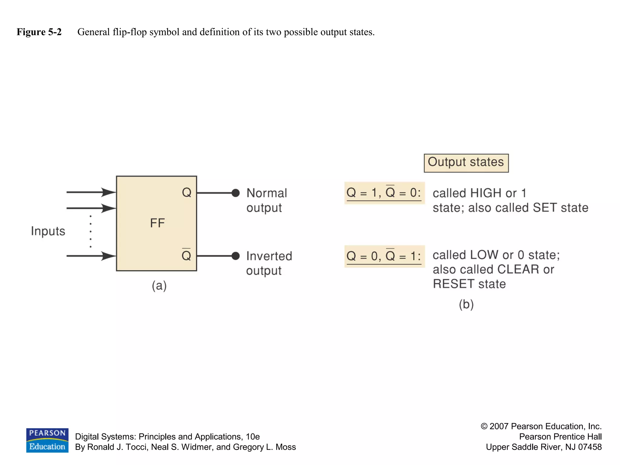
Introduction and definition of flip-flops and their output states.
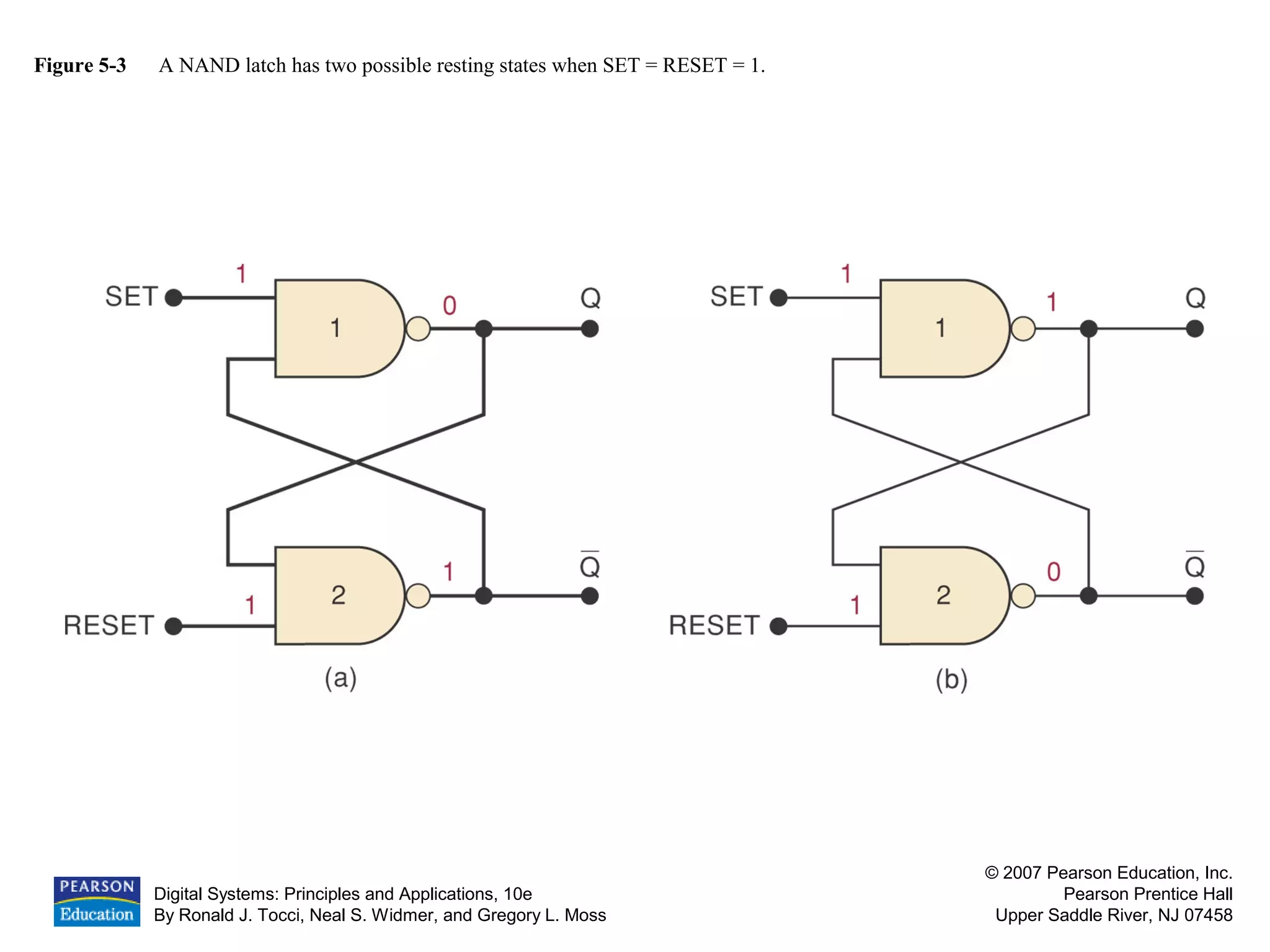
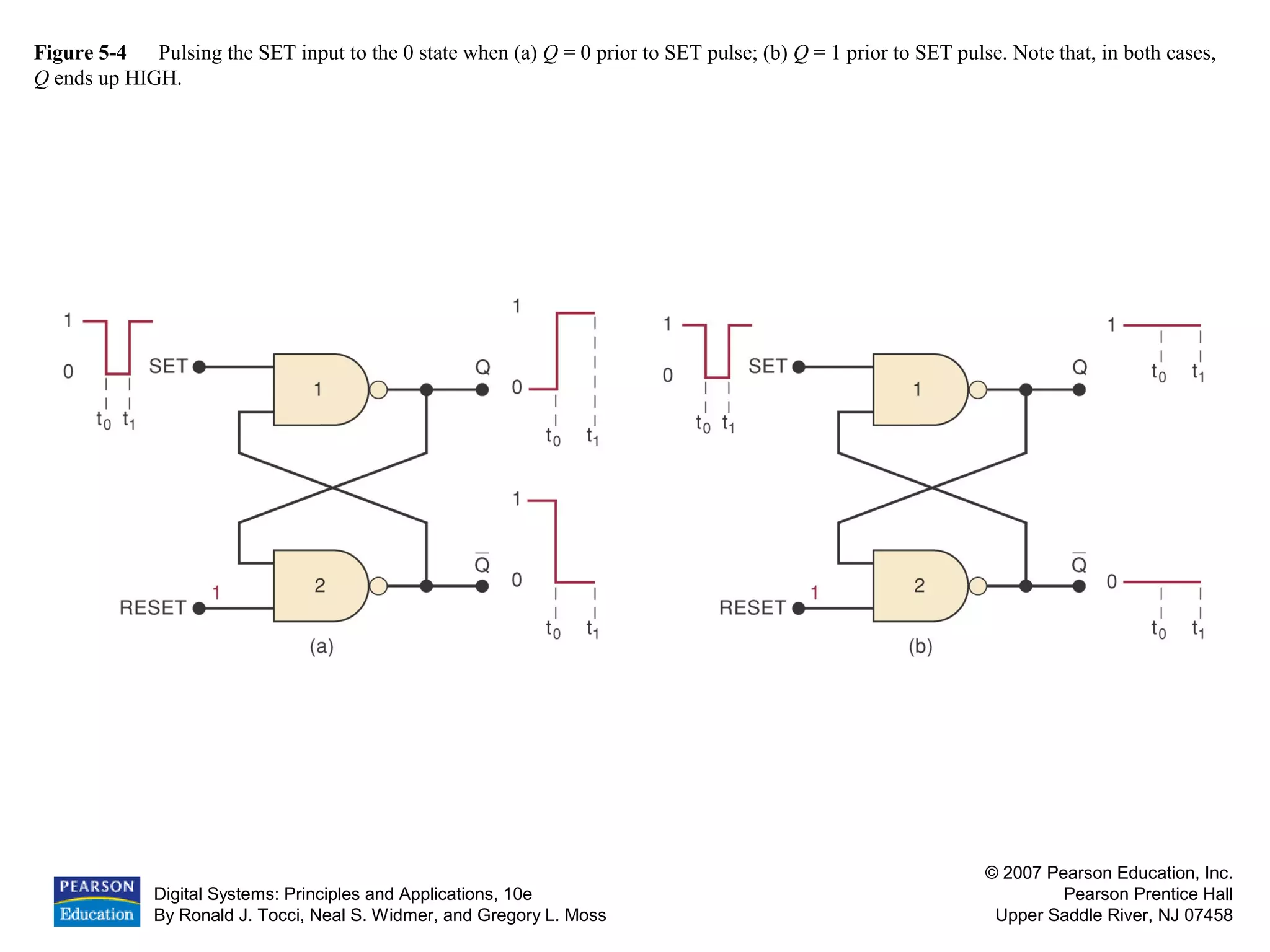
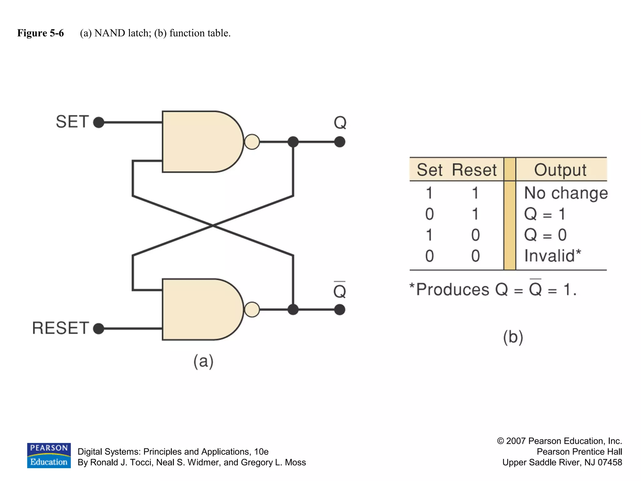
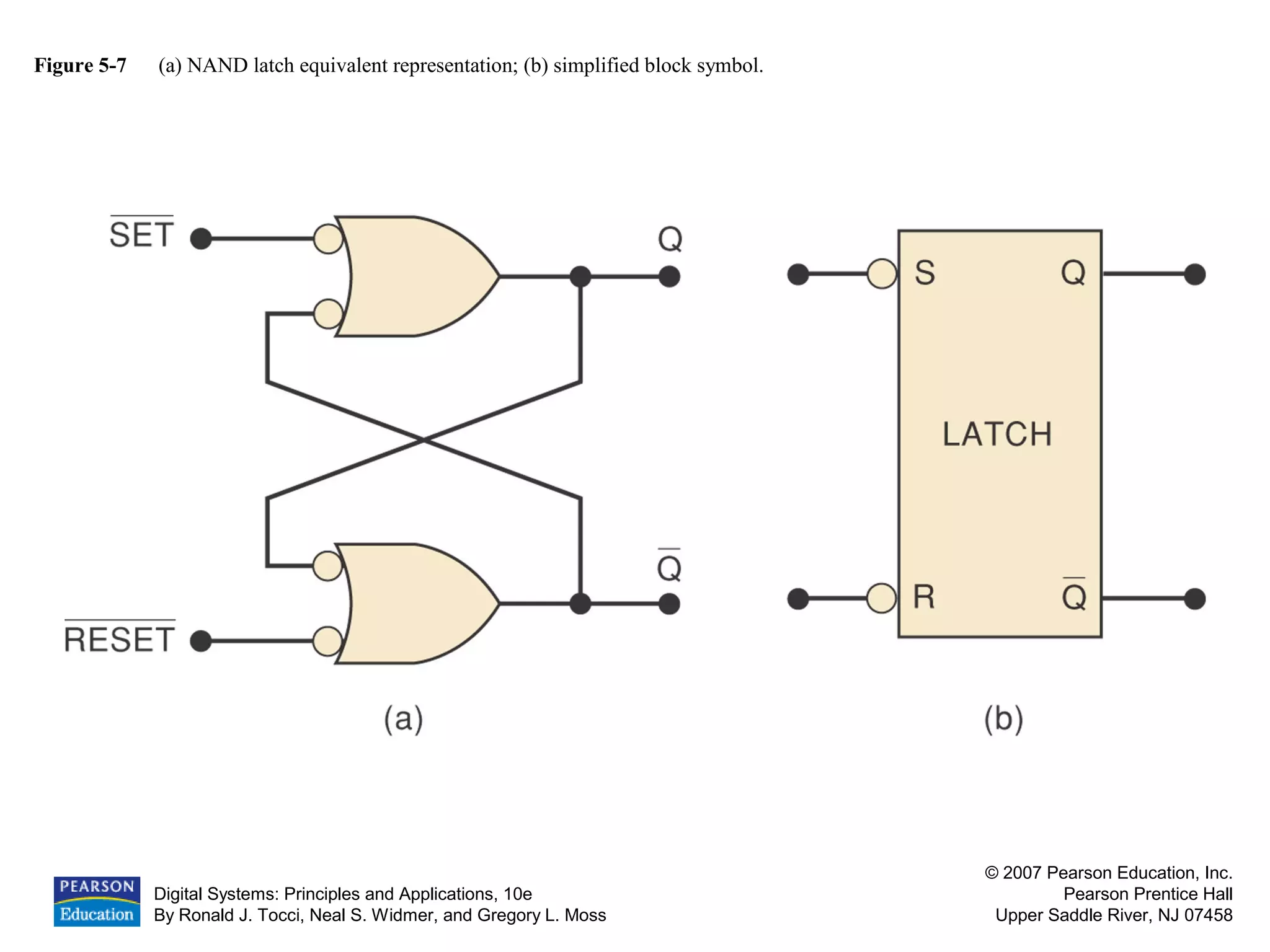
Function and behavior of NAND latch, including operation and function tables.
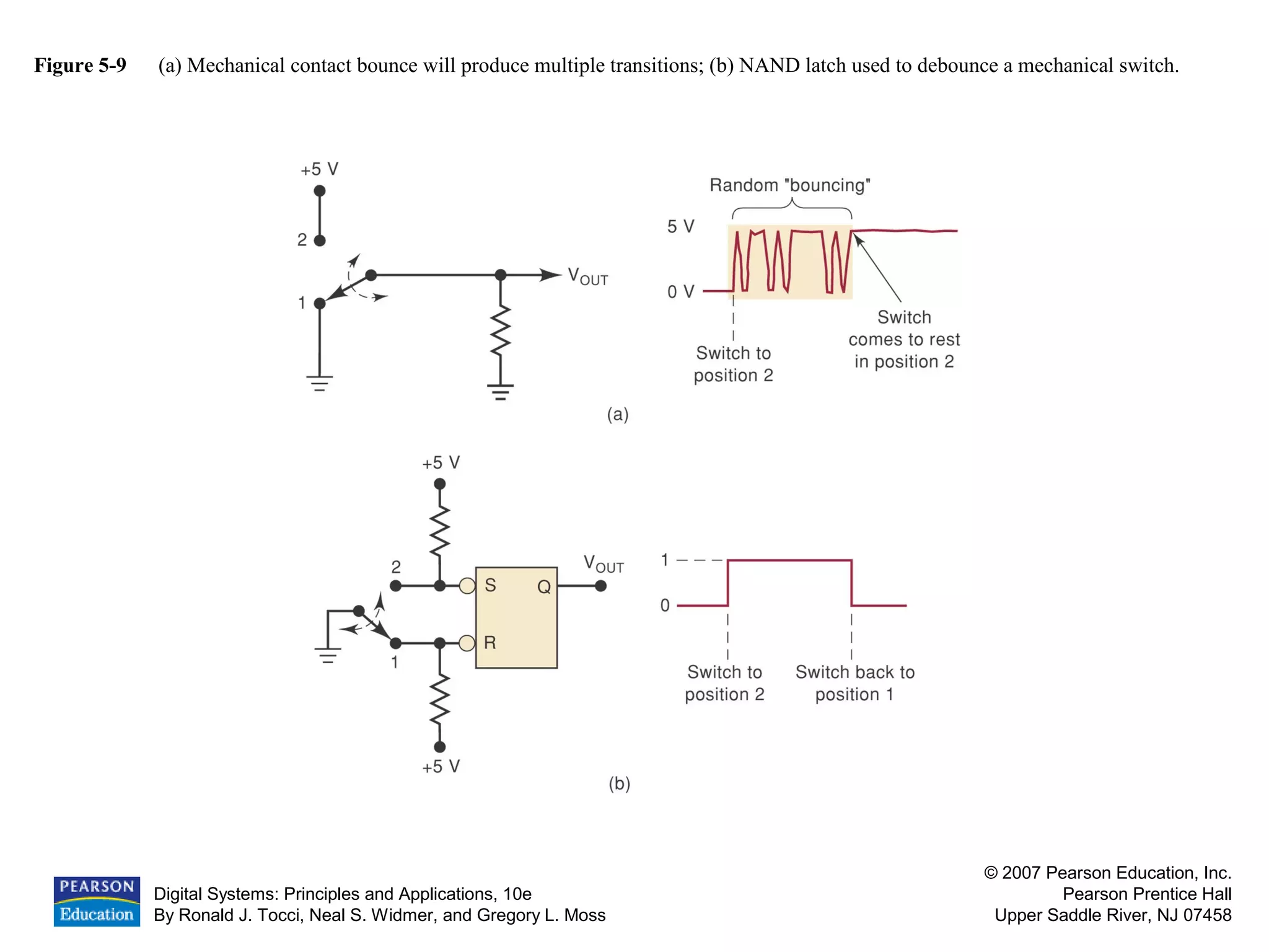
Example of using NAND latch for debouncing mechanical switches.
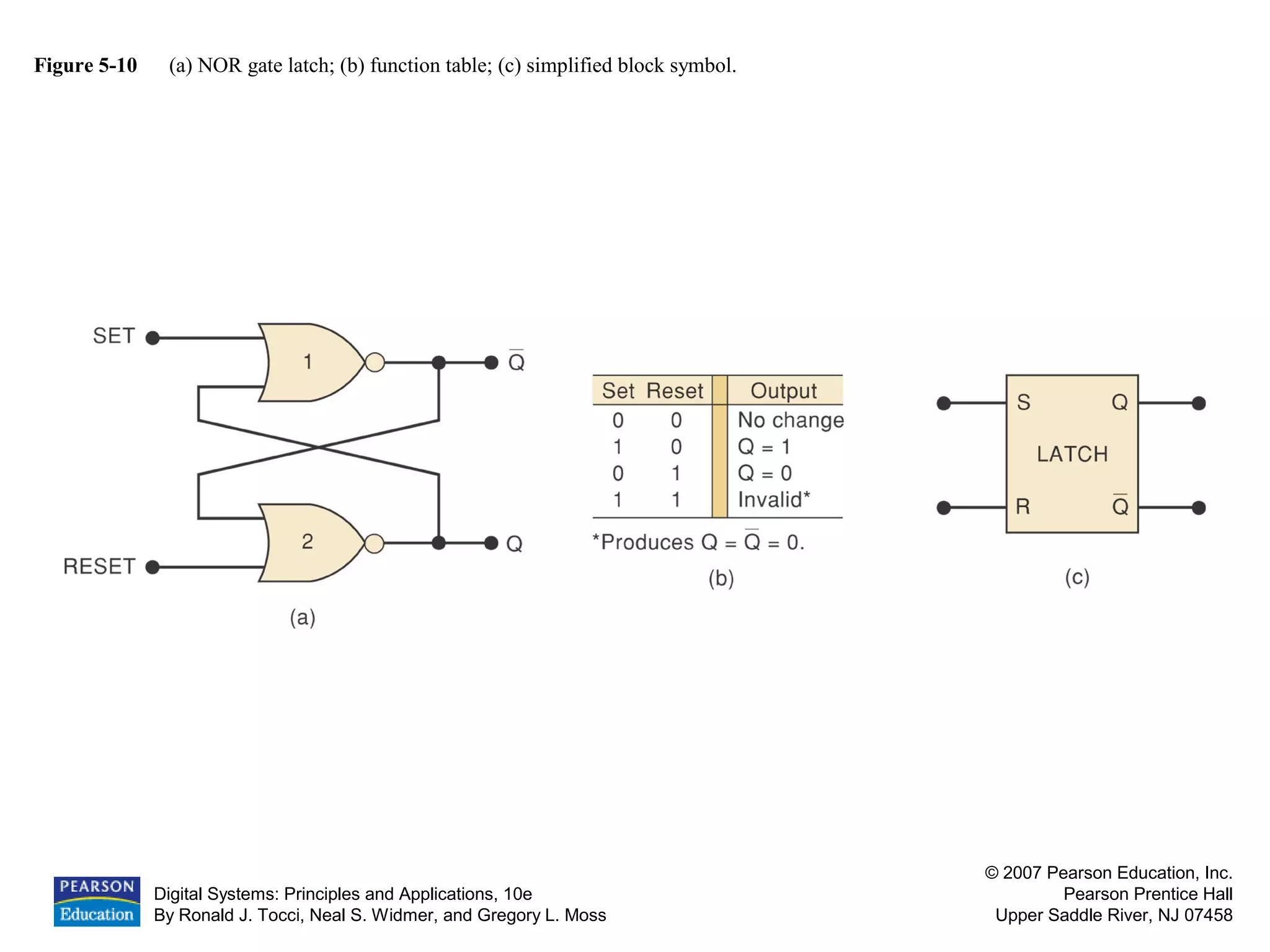
NOR gate latch with function tables and examples.
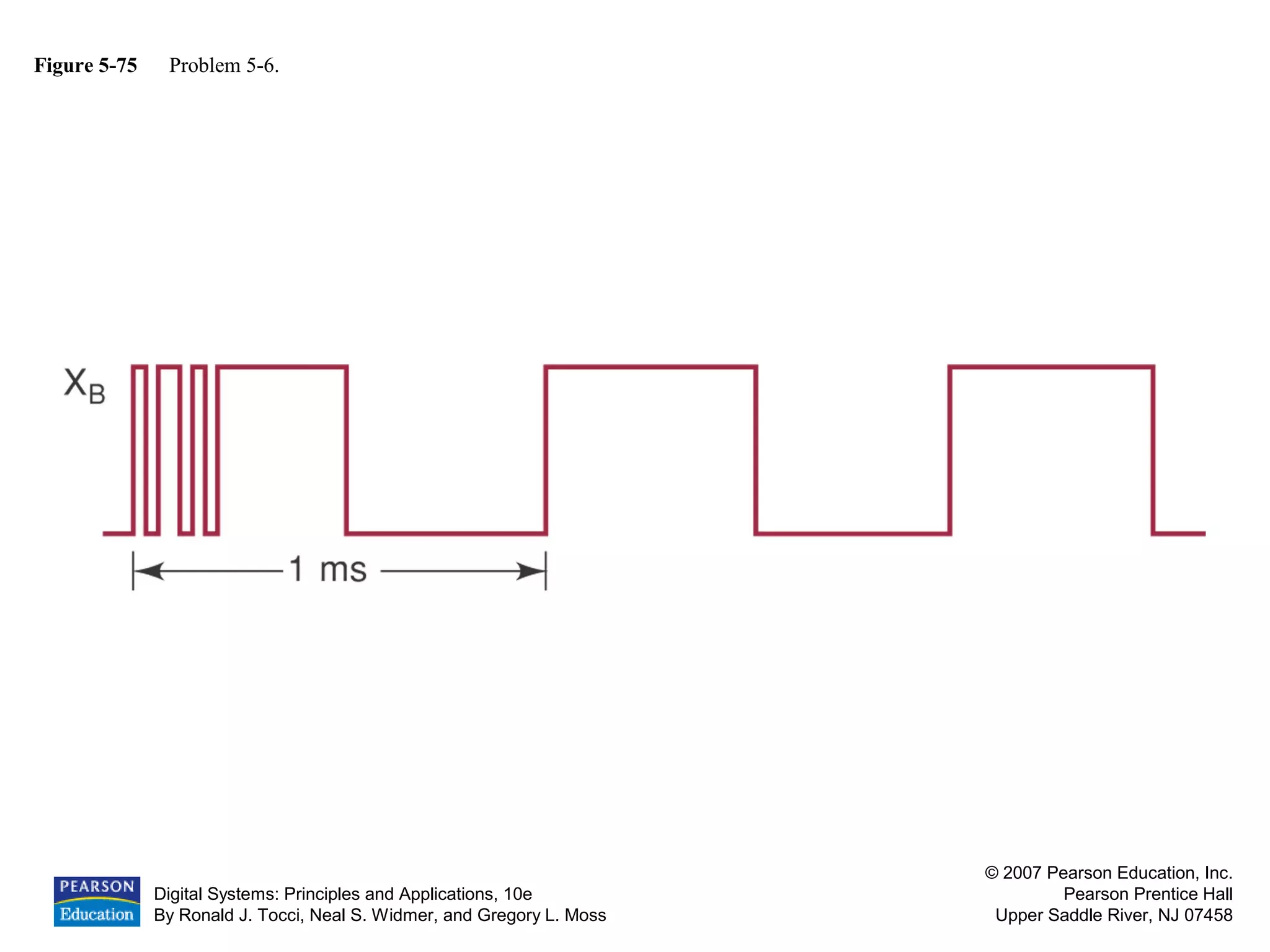
Analysis of positive and negative pulses with examples.
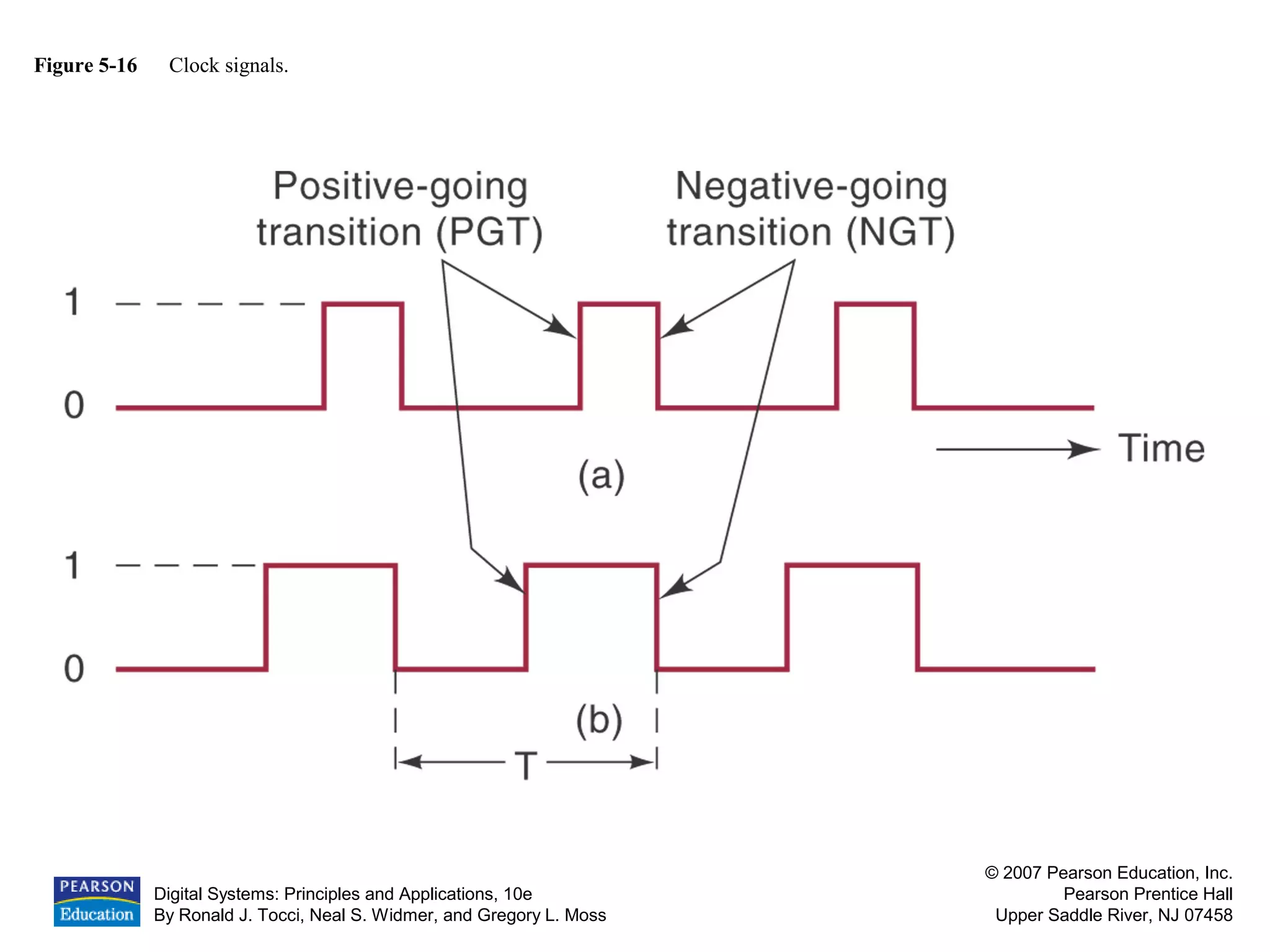
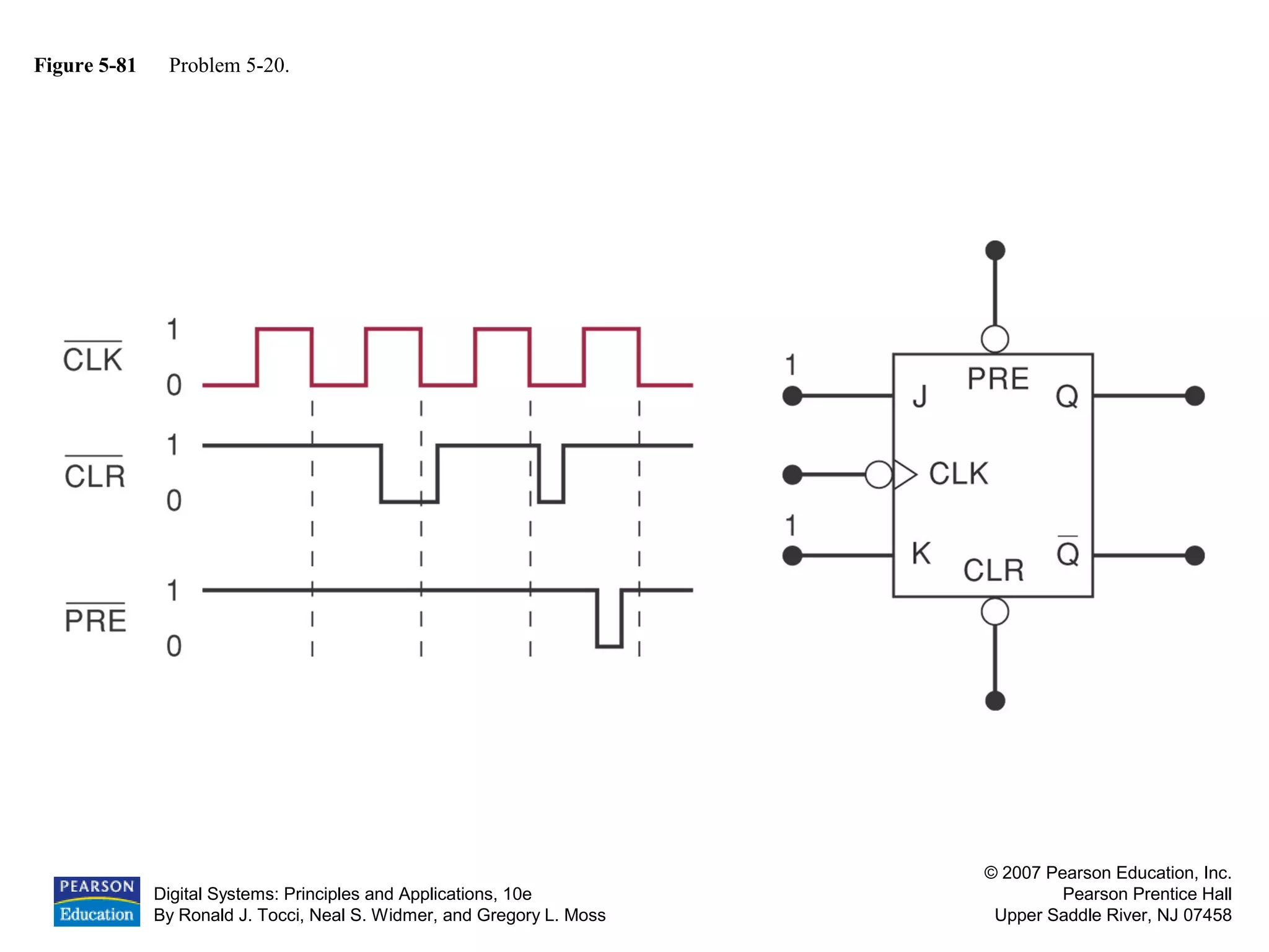
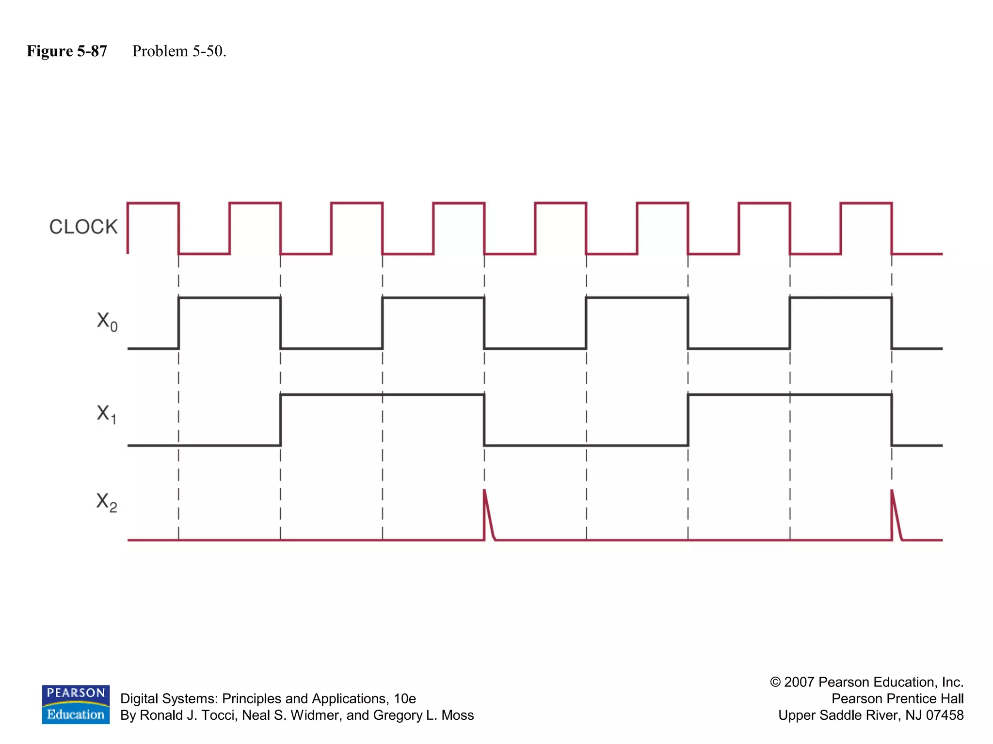
Clock-driven flip-flops with timing diagrams and edge-triggering.
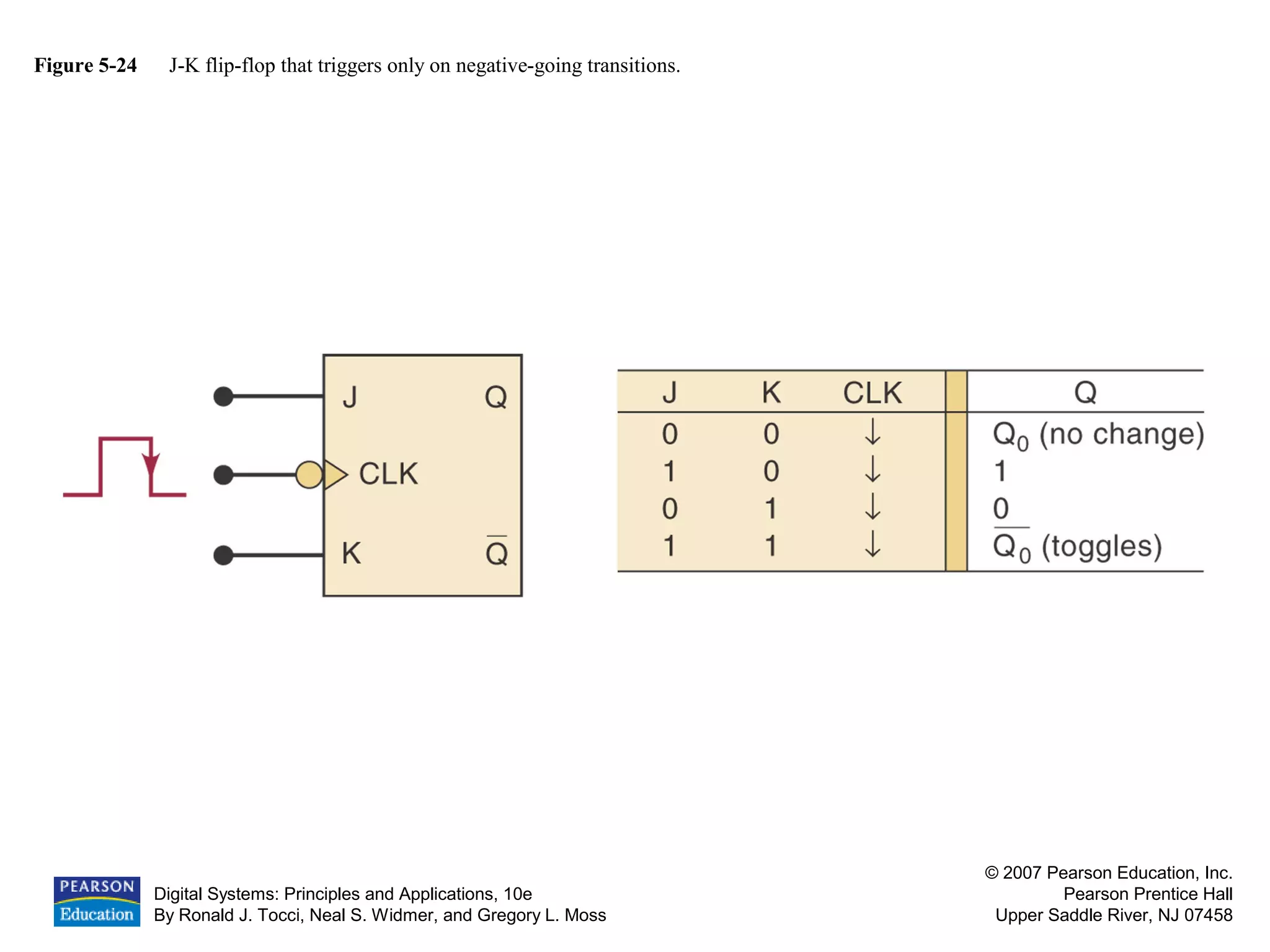
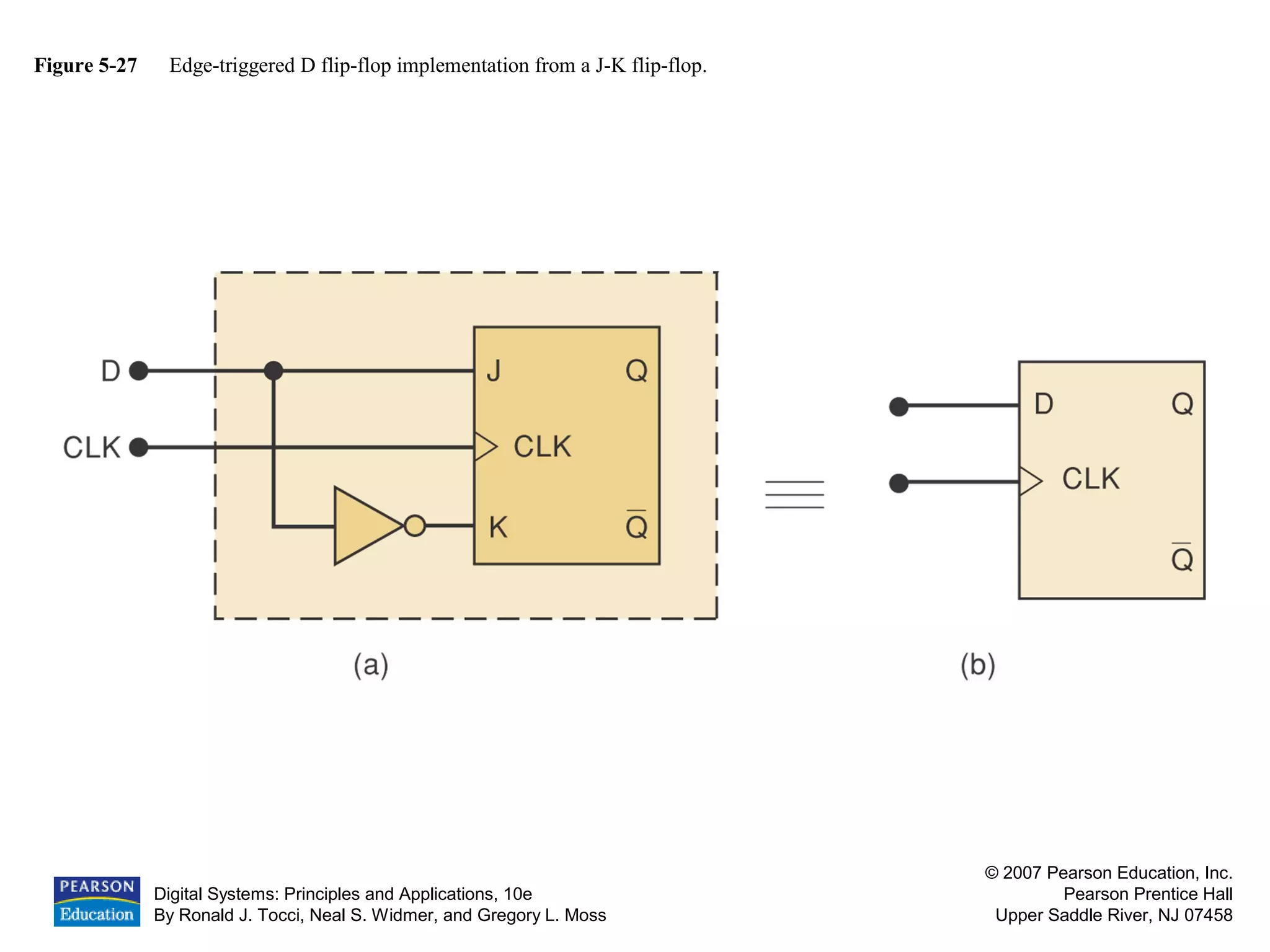
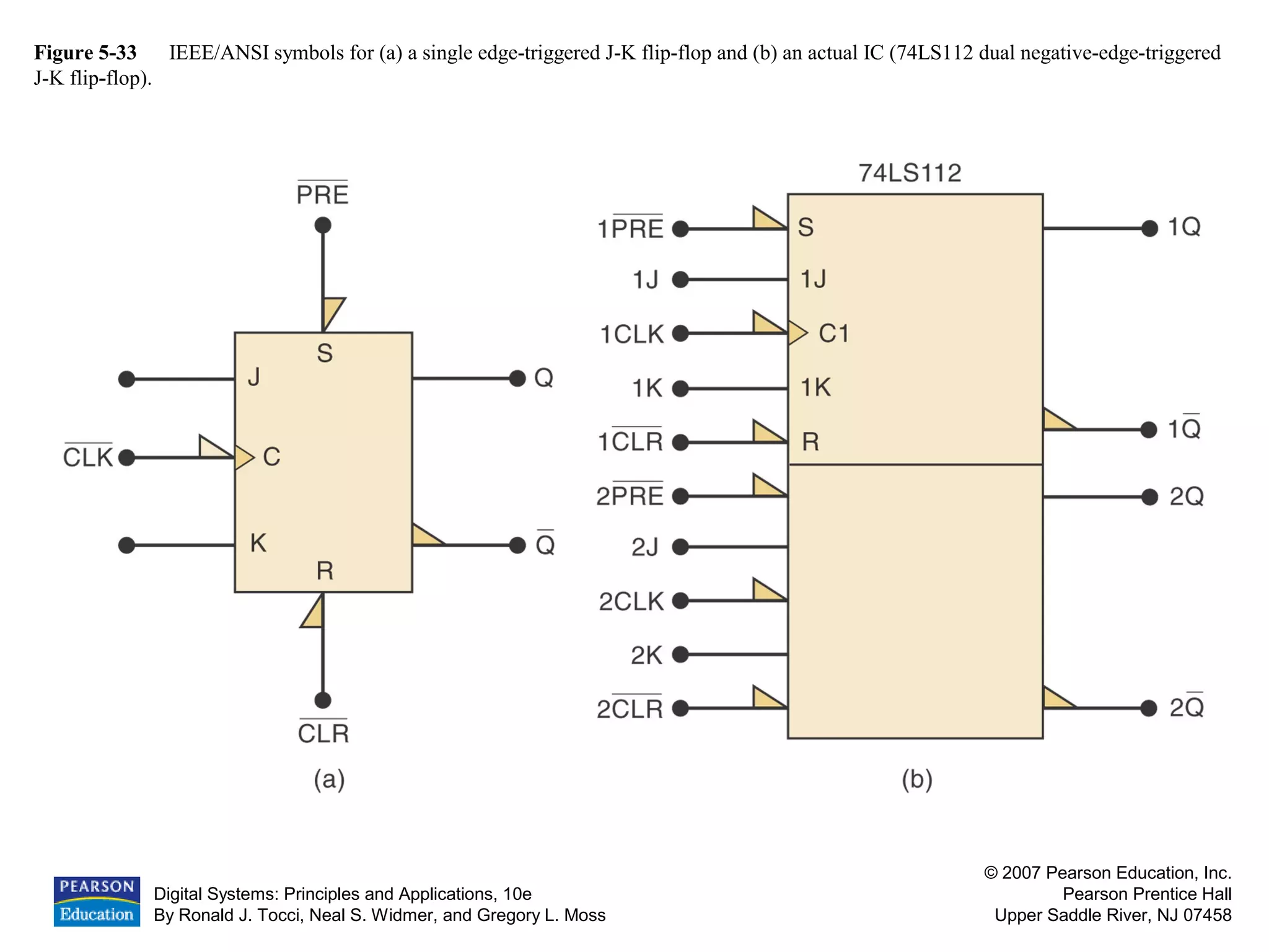
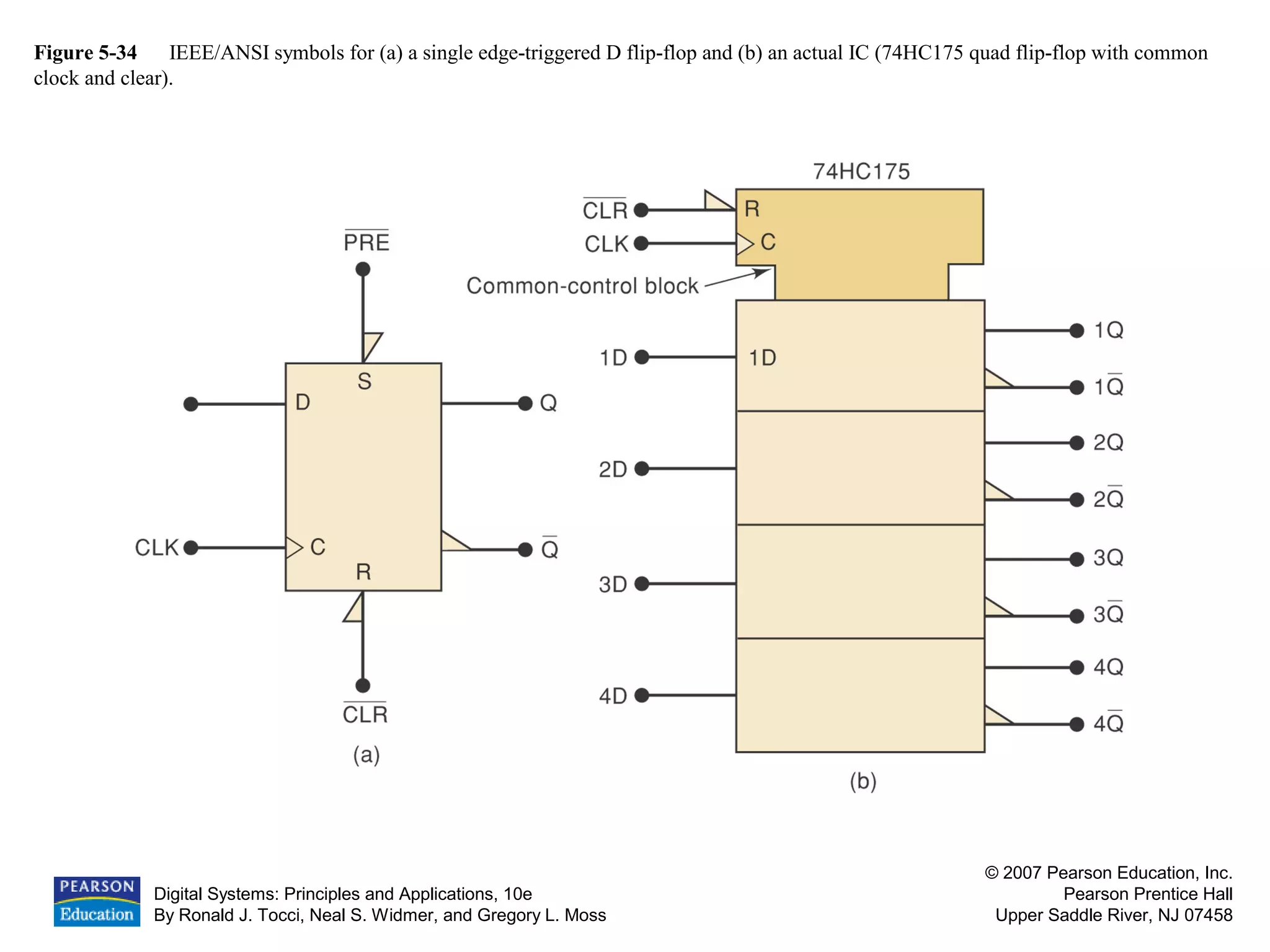
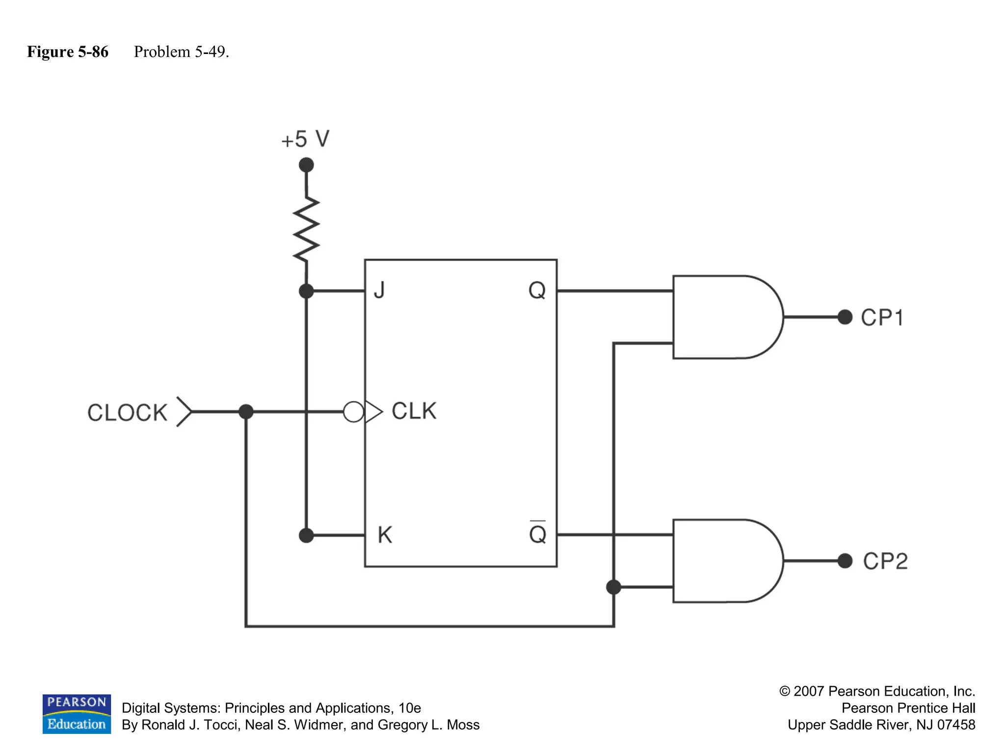
Details on S-R, J-K, and D flip-flops, including their operation and configurations.
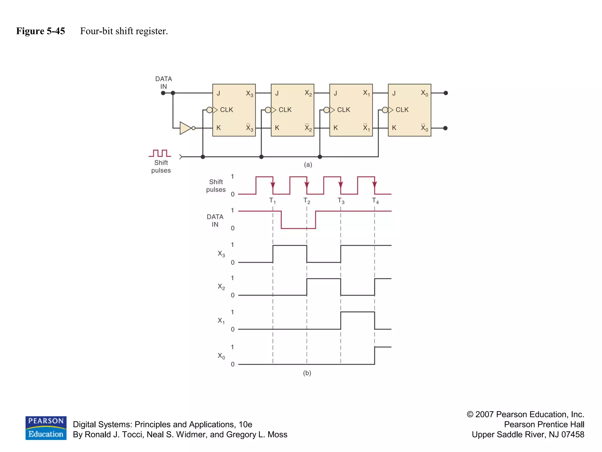
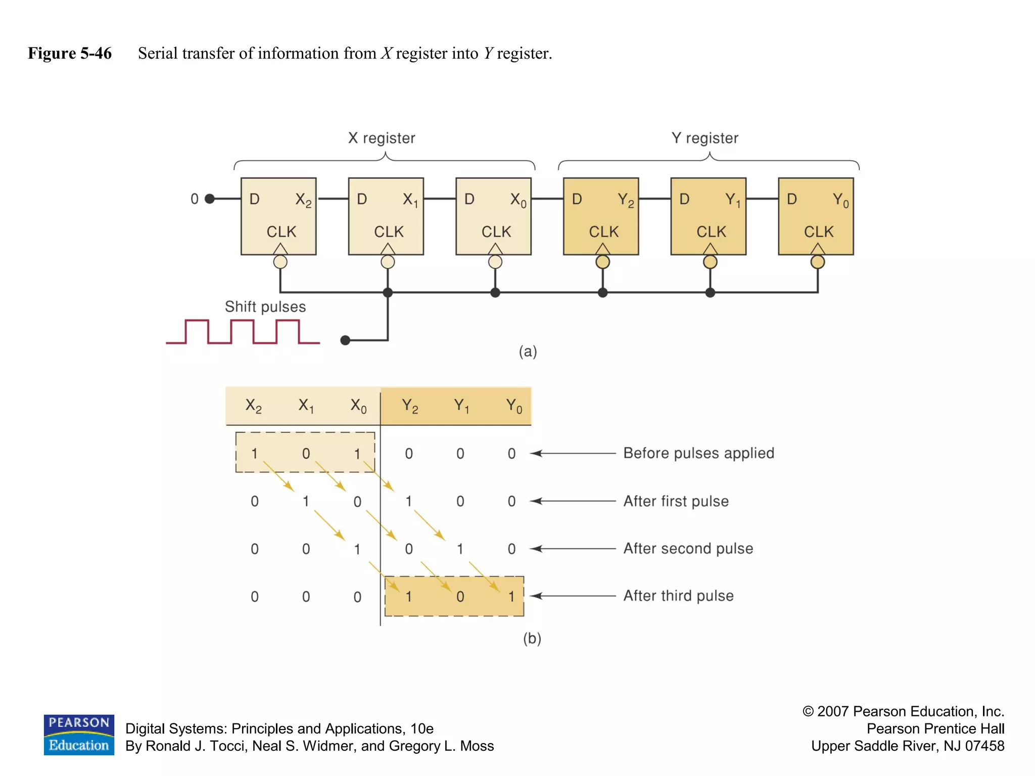
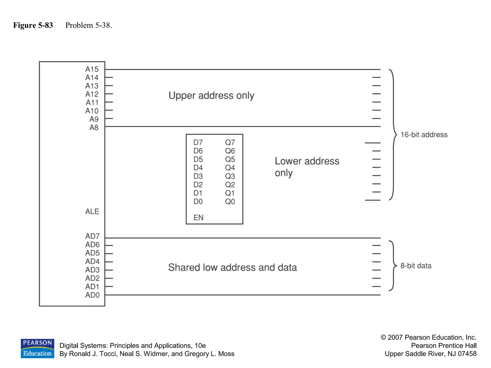
Data transfer operations via different configurations of flip-flops and shift registers.
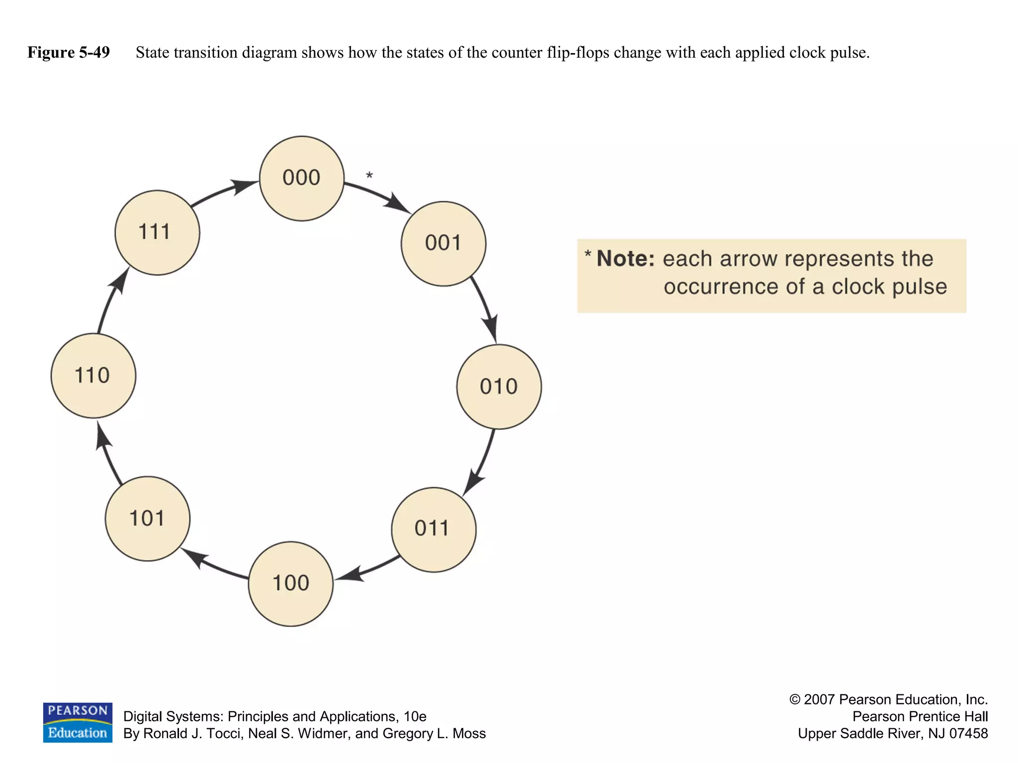
Design and function of binary counters, including transition diagrams.
Examples of data transfer methods including standard and Schmitt-trigger responses.
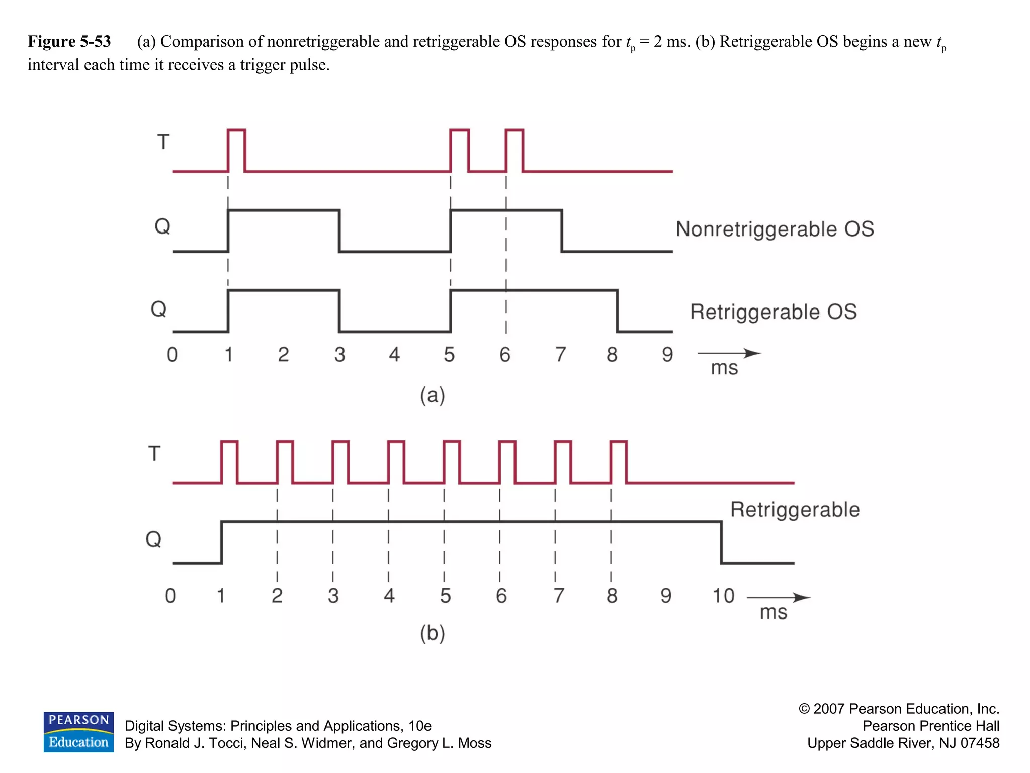
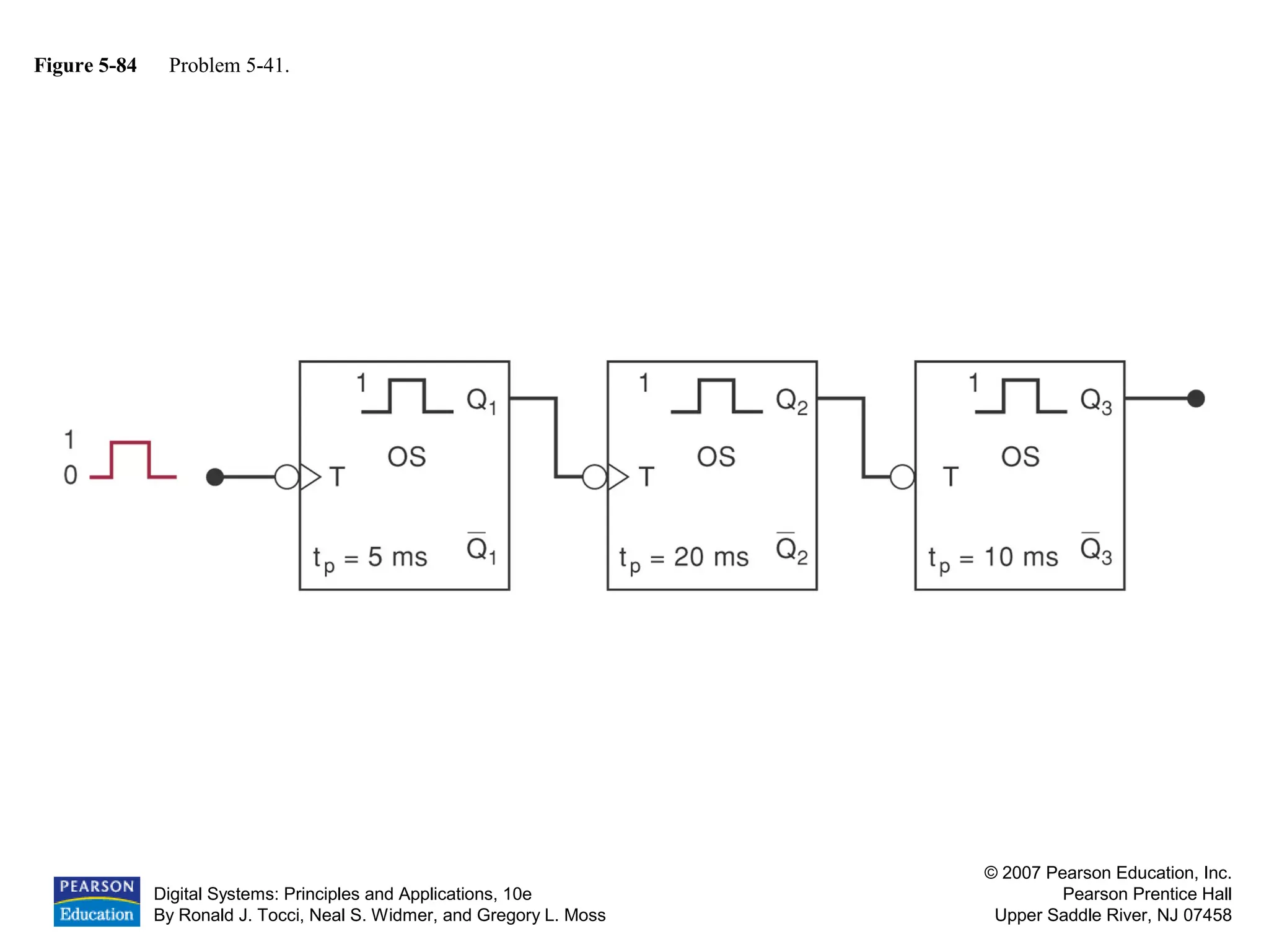
Different oscillator logic using one-shot and Schmitt-trigger configurations.
Simulation and analysis methodologies for JK flip-flops and ripple counters.
Discussion of problem sets relating to digital systems and troubleshooting concepts.