Fire Detection andAlarm
System Basics
Hochiki America Corporation
7051 Village Drive, Suite 100
Buena Park, California 90621
www.hochiki.com
2.
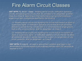
Fire Alarm CircuitClasses
2007 NFPA 72, 6.4.2.1 Class. Initiating device circuits, notification appliance
circuits, and signaling line circuits shall be permitted to be designated as either
Class A or Class B, depending on their performance during nonsimultaneous
single circuit fault conditions as specified by the following:
(1) Initiating device circuits and signaling line circuits that transmit an alarm or
supervisory signal, or notification appliance circuits that allow all connected
devices to operate during a single open or a nonsimultaneous single ground
fault on any circuit conductor, shall be designated as Class A
(2) Initiating device circuits and signaling line circuits that do not transmit an
alarm or supervisory signal, or notification appliance circuits that do not allow
all connected devices to operate beyond the location of a single open on any
circuit conductor, shall be designated as Class B
2007 NFPA 72, 6.4.2.2. An open or ground fault condition shall result in the
annunciation of a trouble signal at the protected premise within 200 seconds as
required in 4.4.7
3.
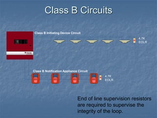
Class B InitiatingDevice Circuit
4.7K
EOLR
4.7K
EOLR
Class B Notification Appliance Circuit
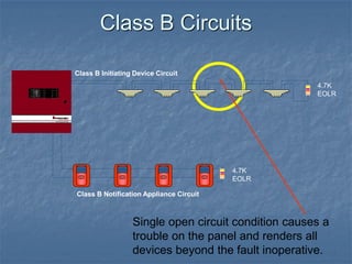
Class B Circuits
End of line supervision resistors
are required to supervise the
integrity of the loop.
4.
Single open circuitcondition causes a
trouble on the panel and renders all
devices beyond the fault inoperative.
Class B Initiating Device Circuit
4.7K
EOLR
4.7K
EOLR
Class B Notification Appliance Circuit
Class B Circuits
5.
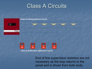
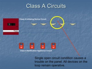
Class A InitiatingDevice Circuit
Class A Notification Appliance Circuit
Class A Circuits
End of line supervision resistors are not
necessary as the loop returns to the
panel and is driven from both ends.
6.
Class A InitiatingDevice Circuit
Class A Notification Appliance Circuit
Class A Circuits
Single open circuit condition causes a
trouble on the panel. All devices on the
loop remain operative.
7.
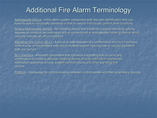
Addressable Device -A fire alarm system component with discreet identification that can
have its status individually identified or that is used to individually control other functions.
Analog Addressable Sensor - An initiating device that transmits a signal indicating varying
degrees of condition as contrasted with a conventional or addressable initiating device, which
can only indicate an off/on condition.
Signaling Line Circuit (SLC) - A circuit or path between any combination of circuit interfaces,
control units, or transmitters over which multiple system input signals or out put signals or
both are carried.
SLC Interface - A system component that connects a signaling line circuit to any
combination of initiating devices, initiating device circuits, notification appliances,
notification appliance circuits, system control outputs and other signaling line
circuits.
Protocol - A language for communicating between control panels and their proprietary devices.
Additional Fire Alarm Terminology
8.
Conventional controlpanels range in size from 1 zone
to over 100 zones.
Zones typically consist of some or all of the initiating
devices in an area or floor of a building.
Some control panels zone capacity is expandable
while others are not, limiting its usefulness if a facility
adds additional buildings or rooms.
Comparing System Types
To better understand today’s newer technology, a firm understanding of the types of systems
available is necessary. The three most popular types of systems installed today are:
•Conventional
•Addressable
•Analog Addressable
Conventional Systems
9.
Conventional Systems
Zone 1
4.7K
EOLR
Zone2
FIRE
FIRE
SILENT KNIGHT
FIRE
FIRE
SILENT KNIGHT
FIRE
FIRE
SILENT KNIGHT
FIRE
FIRE
SILENT KNIGHT
FIRE
FIRE
SILENT KNIGHT
FACP
NAC 1
Multiple devices are combined
into a single zone. Zones can
contain 30 or more devices.
4.7K
EOLR
10.
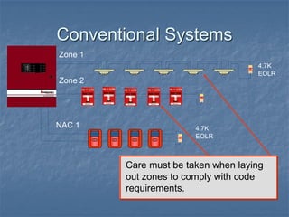
Conventional Systems
Care mustbe taken when laying
out zones to comply with code
requirements.
Zone 1
4.7K
EOLR
Zone 2
FIRE
FIRE
SILENT KNIGHT
NAC 1
4.7K
EOLR
11.
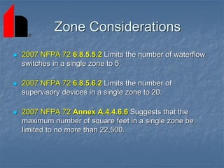
Zone Considerations
2007NFPA 72 6.8.5.5.2 Limits the number of waterflow
switches in a single zone to 5.
2007 NFPA 72 6.8.5.6.2 Limits the number of
supervisory devices in a single zone to 20.
2007 NFPA 72 Annex A.4.4.6.6 Suggests that the
maximum number of square feet in a single zone be
limited to no more than 22,500.
12.
Conventional Systems
Wiring mustbe installed in a
supervised manner either Class A,
or Class B with an EOLR.
Zone #1
4.7K
EOLR
4.7K
EOLR
Zone #2
NAC #1
13.
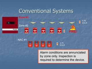
Conventional Systems
Alarm conditionsare annunciated
by zone only. Inspection is
required to determine the device.
Zone #1
4.7K
EOLR
4.7K
EOLR
Zone #2
NAC #1
FIRE!
14.
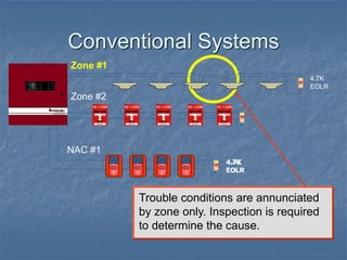
Conventional Systems
Trouble conditionsare annunciated
by zone only. Inspection is required
to determine the cause.
4.7K
EOLR
Zone #1
4.7K
EOLR
4.7K
EOLR
Zone #2
NAC #1
15.
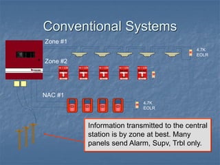
Conventional Systems
Information transmittedto the central
station is by zone at best. Many
panels send Alarm, Supv, Trbl only.
RJ RJ
Zone #1
4.7K
EOLR
4.7K
EOLR
Zone #2
NAC #1
16.
Addressable Systems
Anaddressable systems point capacity is
determined by the amount of SLC “Signaling
Line Circuits” it contains.
Each SLC circuit provides power,
communication, & supervision for all of the
devices connected to it.
Each SLC can accommodate over 100
addressable devices, depending upon the
manufacturer.
FACP
17.
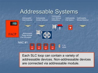
Addressable Systems
FACP
Each SLCloop can contain a variety of
addressable devices. Non-addressable devices
are connected via addressable module.
FIRE
FIRE
SILENT KNIGHT
Addressable
Pull Station
Addressable
Heat Detector
4.7K
EOLR
NAC #1
Addressable
Smoke Detector
Addressable
Input Module
(Waterflow)
Addressable
Smoke Detector
Addressable
Relay Module
(Fan Shutdown)
18.
Addressable Systems
Each pointon the SLC loop is given
a unique address when installed.
001 002
003
004
005
006
FACP
FIRE
FIRE
SILENT KNIGHT
Addressable
Pull Station
Addressable
Relay Module
(Fan Shutdown)
Addressable
Heat Detector
4.7K
EOLR
NAC #1
Addressable
Smoke Detector
Addressable
Input Module
(Waterflow)
Addressable
Smoke Detector
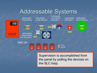
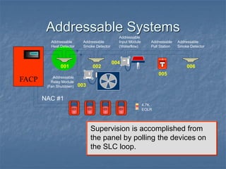
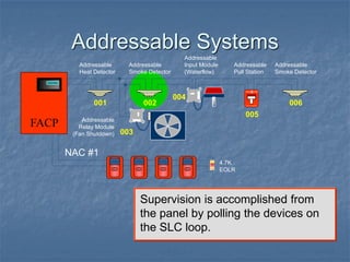
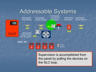
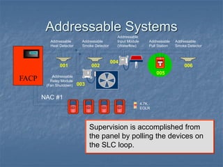
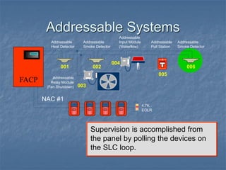
19.
Addressable Systems
Supervision isaccomplished from
the panel by polling the devices on
the SLC loop.
001 002
003
004
005
006
FACP
FIRE
FIRE
SILENT KNIGHT
Addressable
Pull Station
Addressable
Relay Module
(Fan Shutdown)
Addressable
Heat Detector
4.7K
EOLR
Addressable
Smoke Detector
Addressable
Input Module
(Waterflow)
Addressable
Smoke Detector
NAC #1
20.
Addressable Systems
Supervision isaccomplished from
the panel by polling the devices on
the SLC loop.
001 002
003
004
005
006
FACP
FIRE
FIRE
SILENT KNIGHT
Addressable
Pull Station
Addressable
Relay Module
(Fan Shutdown)
Addressable
Heat Detector
4.7K
EOLR
Addressable
Smoke Detector
Addressable
Input Module
(Waterflow)
Addressable
Smoke Detector
NAC #1
21.
Addressable Systems
Supervision isaccomplished from
the panel by polling the devices on
the SLC loop.
001 002
003
004
005
006
FACP
FIRE
FIRE
SILENT KNIGHT
Addressable
Pull Station
Addressable
Relay Module
(Fan Shutdown)
Addressable
Heat Detector
4.7K
EOLR
Addressable
Smoke Detector
Addressable
Input Module
(Waterflow)
Addressable
Smoke Detector
NAC #1
22.
Addressable Systems
Supervision isaccomplished from
the panel by polling the devices on
the SLC loop.
001 002
003
004
005
006
FACP
FIRE
FIRE
SILENT KNIGHT
Addressable
Pull Station
Addressable
Relay Module
(Fan Shutdown)
Addressable
Heat Detector
4.7K
EOLR
Addressable
Smoke Detector
Addressable
Input Module
(Waterflow)
Addressable
Smoke Detector
NAC #1
23.
Addressable Systems
Supervision isaccomplished from
the panel by polling the devices on
the SLC loop.
001 002
003
004
005
006
FACP
FIRE
FIRE
SILENT KNIGHT
Addressable
Pull Station
Addressable
Relay Module
(Fan Shutdown)
Addressable
Heat Detector
4.7K
EOLR
Addressable
Smoke Detector
Addressable
Input Module
(Waterflow)
Addressable
Smoke Detector
NAC #1
24.
Addressable Systems
Supervision isaccomplished from
the panel by polling the devices on
the SLC loop.
001 002
003
004
005
006
FACP
FIRE
FIRE
SILENT KNIGHT
Addressable
Pull Station
Addressable
Relay Module
(Fan Shutdown)
Addressable
Heat Detector
4.7K
EOLR
Addressable
Smoke Detector
Addressable
Input Module
(Waterflow)
Addressable
Smoke Detector
NAC #1
25.
Addressable Systems
Supervision isaccomplished from
the panel by polling the devices on
the SLC loop.
001 002
003
004
005
006
FACP
FIRE
FIRE
SILENT KNIGHT
Addressable
Pull Station
Addressable
Relay Module
(Fan Shutdown)
Addressable
Heat Detector
4.7K
EOLR
Addressable
Smoke Detector
Addressable
Input Module
(Waterflow)
Addressable
Smoke Detector
NAC #1
26.
Addressable Systems
Supervision isaccomplished from
the panel by polling the devices on
the SLC loop.
001 002
003
004
005
006
FACP
FIRE
FIRE
SILENT KNIGHT
Addressable
Pull Station
Addressable
Relay Module
(Fan Shutdown)
Addressable
Heat Detector
4.7K
EOLR
Addressable
Smoke Detector
Addressable
Input Module
(Waterflow)
Addressable
Smoke Detector
NAC #1
27.
Addressable Systems
Supervision isaccomplished from
the panel by polling the devices on
the SLC loop.
001 002
003
004
005
006
FACP
FIRE
FIRE
SILENT KNIGHT
Addressable
Pull Station
Addressable
Relay Module
(Fan Shutdown)
Addressable
Heat Detector
4.7K
EOLR
Addressable
Smoke Detector
Addressable
Input Module
(Waterflow)
Addressable
Smoke Detector
NAC #1
28.
Addressable Systems
Supervision isaccomplished from
the panel by polling the devices on
the SLC loop.
001 002
003
004
005
006
FACP
FIRE
FIRE
SILENT KNIGHT
Addressable
Pull Station
Addressable
Relay Module
(Fan Shutdown)
Addressable
Heat Detector
4.7K
EOLR
Addressable
Smoke Detector
Addressable
Input Module
(Waterflow)
Addressable
Smoke Detector
NAC #1
29.
Addressable Systems
Supervision isaccomplished from
the panel by polling the devices on
the SLC loop.
001 002
003
004
005
006
FACP
FIRE
FIRE
SILENT KNIGHT
Addressable
Pull Station
Addressable
Relay Module
(Fan Shutdown)
Addressable
Heat Detector
4.7K
EOLR
Addressable
Smoke Detector
Addressable
Input Module
(Waterflow)
Addressable
Smoke Detector
NAC #1
30.
Addressable Systems
Supervision isaccomplished from
the panel by polling the devices on
the SLC loop.
001 002
003
004
005
006
FIRE
FIRE
SILENT KNIGHT
Addressable
Pull Station
Addressable
Relay Module
(Fan Shutdown)
Addressable
Heat Detector
4.7K
EOLR
Addressable
Smoke Detector
Addressable
Input Module
(Waterflow)
Addressable
Smoke Detector
FACP
NAC #1
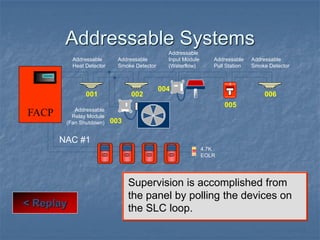
31.
Addressable Systems
Supervision isaccomplished from
the panel by polling the devices on
the SLC loop.
< Replay
001 002
003
004
005
006
FACP
FIRE
FIRE
SILENT KNIGHT
Addressable
Pull Station
Addressable
Relay Module
(Fan Shutdown)
Addressable
Heat Detector
4.7K
EOLR
Addressable
Smoke Detector
Addressable
Input Module
(Waterflow)
Addressable
Smoke Detector
NAC #1
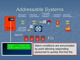
32.
Addressable Systems
Alarm conditionsare annunciated
by point allowing responding
personnel to quickly find the fire.
ALARM POINT 006
LOBBY SMOKE DETECTOR
001 002
003
004
005
006
FACP
FIRE
FIRE
SILENT KNIGHT
Addressable
Pull Station
Addressable
Relay Module
(Fan Shutdown)
Addressable
Heat Detector
4.7K
EOLR
Addressable
Smoke Detector
Addressable
Input Module
(Waterflow)
Addressable
Smoke Detector
NAC #1
FIRE!
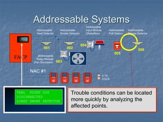
33.
Addressable Systems
Trouble conditionscan be located
more quickly by analyzing the
affected points.
TRBL POINT 006
DISCONNECTED
LOBBY SMOKE DETECTOR
001 002
003
004
005
006
FACP
FIRE
FIRE
SILENT KNIGHT
Addressable
Pull Station
Addressable
Relay Module
(Fan Shutdown)
Addressable
Heat Detector
4.7K
EOLR
Addressable
Smoke Detector
Addressable
Input Module
(Waterflow)
Addressable
Smoke Detector
NAC #1
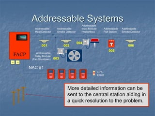
34.
Addressable Systems
More detailedinformation can be
sent to the central station aiding in
a quick resolution to the problem.
RJ
RJ
001 002
003
004
005
006
FACP
FIRE
FIRE
SILENT KNIGHT
Addressable
Pull Station
Addressable
Relay Module
(Fan Shutdown)
Addressable
Heat Detector
4.7K
EOLR
Addressable
Smoke Detector
Addressable
Input Module
(Waterflow)
Addressable
Smoke Detector
NAC #1
35.
Addressable Systems
Since supervisionis accomplished
through polling, t-tapped wiring is
permitted. (Class B wiring)
001 002
003
004
005
006
FACP
FIRE
FIRE
SILENT KNIGHT
Addressable
Pull Station
Addressable
Relay Module
(Fan Shutdown)
Addressable
Heat Detector
4.7K
EOLR
Addressable
Smoke Detector
Addressable
Input Module
(Waterflow)
Addressable
Smoke Detector
NAC #1
36.
Addressable Systems
Many systemssupport flexible
input/output programming to link
initiating devices to outputs.
001 002
003
004
005
006
FACP
FIRE
FIRE
SILENT KNIGHT
Addressable
Pull Station
Addressable
Relay Module
(Fan Shutdown)
Addressable
Heat Detector
4.7K
EOLR
Addressable
Smoke Detector
Addressable
Input Module
(Waterflow)
Addressable
Smoke Detector
NAC #1
FIRE!
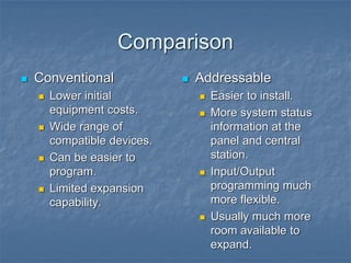
37.
Comparison
Conventional
Lowerinitial
equipment costs.
Wide range of
compatible devices.
Can be easier to
program.
Limited expansion
capability.
Addressable
Easier to install.
More system status
information at the
panel and central
station.
Input/Output
programming much
more flexible.
Usually much more
room available to
expand.
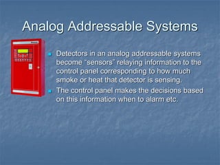
38.
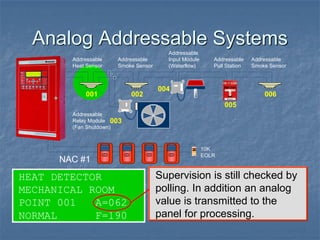
Analog Addressable Systems
Detectors in an analog addressable systems
become “sensors” relaying information to the
control panel corresponding to how much
smoke or heat that detector is sensing.
The control panel makes the decisions based
on this information when to alarm etc.
39.
Analog Addressable Systems
Addressable
RelayModule
(Fan Shutdown)
Addressable
Heat Sensor
10K
EOLR
Addressable
Smoke Sensor
Addressable
Input Module
(Waterflow)
001 002
003
004
005
Addressable
Pull Station
Addressable
Smoke Sensor
006
HEAT DETECTOR
MECHANICAL ROOM
POINT 001 A=062
NORMAL F=190
Supervision is still checked by
polling. In addition an analog
value is transmitted to the
panel for processing.
NAC #1
40.
Analog Addressable Systems
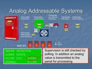
SMOKEDETECTOR
LOBBY NORTH
POINT 002 A=060
NORMAL F=188
Supervision is still checked by
polling. In addition an analog
value is transmitted to the
panel for processing.
Addressable
Relay Module
(Fan Shutdown)
Addressable
Heat Sensor
Addressable
Smoke Sensor
Addressable
Input Module
(Waterflow)
001 002
003
004
005
Addressable
Pull Station
Addressable
Smoke Detector
006
10K
EOLR
NAC #1
41.
Analog Addressable Systems
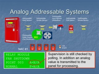
RELAYMODULE
FAN SHUTDOWN
POINT 003 A=N/A
NORMAL F=N/A
Supervision is still checked by
polling. In addition an analog
value is transmitted to the
panel for processing.
Addressable
Relay Module
(Fan Shutdown)
Addressable
Heat Sensor
Addressable
Smoke Sensor
Addressable
Input Module
(Waterflow)
001 002
003
004
005
Addressable
Pull Station
Addressable
Smoke Sensor
006
10K
EOLR
NAC #1
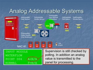
42.
Analog Addressable Systems
INPUTMODULE
WATERFLOW
POINT 004 A=N/A
NORMAL F=N/A
Supervision is still checked by
polling. In addition an analog
value is transmitted to the
panel for processing.
Addressable
Relay Module
(Fan Shutdown)
Addressable
Heat Sensor
Addressable
Smoke Sensor
Addressable
Input Module
(Waterflow)
001 002
003
004
005
Addressable
Pull Station
Addressable
Smoke Sensor
006
10K
EOLR
NAC #1
43.
Analog Addressable Systems
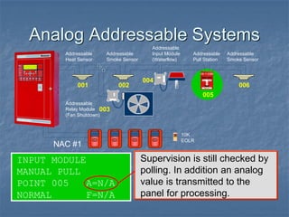
Supervisionis still checked by
polling. In addition an analog
value is transmitted to the
panel for processing.
INPUT MODULE
MANUAL PULL
POINT 005 A=N/A
NORMAL F=N/A
Addressable
Relay Module
(Fan Shutdown)
Addressable
Heat Sensor
Addressable
Smoke Sensor
Addressable
Input Module
(Waterflow)
001 002
003
004
005
Addressable
Pull Station
Addressable
Smoke Sensor
006
10K
EOLR
NAC #1
44.
Analog Addressable Systems
SMOKEDETECTOR
FRONT DESK
POINT 006 A=061
NORMAL F=189
Supervision is still checked by
polling. In addition an analog
value is transmitted to the
panel for processing.
Addressable
Relay Module
(Fan Shutdown)
Addressable
Heat Sensor
Addressable
Smoke Sensor
Addressable
Input Module
(Waterflow)
001 002
003
004
005
Addressable
Pull Station
Addressable
Smoke Sensor
006
10K
EOLR
NAC #1
45.
Analog Addressable Systems
HEATDETECTOR
MECHANICAL ROOM
POINT 001 A=062
NORMAL F=190
Supervision is still checked by
polling. In addition an analog
value is transmitted to the
panel for processing.
Addressable
Relay Module
(Fan Shutdown)
Addressable
Heat Sensor
Addressable
Smoke Sensor
Addressable
Input Module
(Waterflow)
001 002
003
004
005
Addressable
Pull Station
Addressable
Smoke Sensor
006
10K
EOLR
NAC #1
46.
Analog Addressable Systems
SMOKEDETECTOR
LOBBY NORTH
POINT 002 A=060
NORMAL F=188
Supervision is still checked by
polling. In addition an analog
value is transmitted to the
panel for processing.
Addressable
Relay Module
(Fan Shutdown)
Addressable
Heat Sensor
Addressable
Smoke Sensor
Addressable
Input Module
(Waterflow)
001 002
003
004
005
Addressable
Pull Station
Addressable
Smoke Sensor
006
10K
EOLR
NAC #1
47.
Analog Addressable Systems
RELAYMODULE
FAN SHUTDOWN
POINT 003 A=N/A
NORMAL F=N/A
Supervision is still checked by
polling. In addition an analog
value is transmitted to the
panel for processing.
Addressable
Relay Module
(Fan Shutdown)
Addressable
Heat Sensor
Addressable
Smoke Sensor
Addressable
Input Module
(Waterflow)
001 002
003
004
005
Addressable
Pull Station
Addressable
Smoke Sensor
006
10K
EOLR
NAC #1
48.
Analog Addressable Systems
INPUTMODULE
WATERFLOW
POINT 004 A=N/A
NORMAL F=N/A
Supervision is still checked by
polling. In addition an analog
value is transmitted to the
panel for processing.
Addressable
Relay Module
(Fan Shutdown)
Addressable
Heat Sensor
Addressable
Smoke Sensor
Addressable
Input Module
(Waterflow)
001 002
003
004
005
Addressable
Pull Station
Addressable
Smoke Sensor
006
10K
EOLR
NAC #1
49.
Analog Addressable Systems
Supervisionis still checked by
polling. In addition an analog
value is transmitted to the
panel for processing.
INPUT MODULE
MANUAL PULL
POINT 005 A=N/A
NORMAL F=N/A
Addressable
Relay Module
(Fan Shutdown)
Addressable
Heat Sensor
Addressable
Smoke Sensor
Addressable
Input Module
(Waterflow)
001 002
003
004
005
Addressable
Pull Station
Addressable
Smoke Sensor
006
10K
EOLR
NAC #1
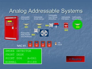
50.
Analog Addressable Systems
SMOKEDETECTOR
FRONT DESK
POINT 006 A=061
NORMAL F=189
< Replay
Addressable
Relay Module
(Fan Shutdown)
Addressable
Heat Sensor
Addressable
Smoke Sensor
Addressable
Input Module
(Waterflow)
001 002
003
004
005
Addressable
Pull Station
Addressable
Smoke Sensor
006
10K
EOLR
NAC #1
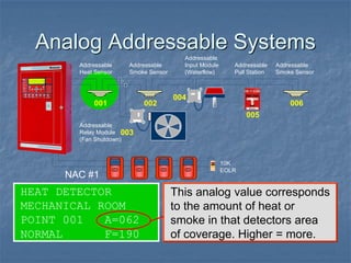
51.
Analog Addressable Systems
Thisanalog value corresponds
to the amount of heat or
smoke in that detectors area
of coverage. Higher = more.
HEAT DETECTOR
MECHANICAL ROOM
POINT 001 A=062
NORMAL F=190
Addressable
Relay Module
(Fan Shutdown)
Addressable
Heat Sensor
Addressable
Smoke Sensor
Addressable
Input Module
(Waterflow)
001 002
003
004
005
Addressable
Pull Station
Addressable
Smoke Sensor
006
10K
EOLR
NAC #1
52.
Analog Addressable Systems
Ifthe analog value exceeds
the alarm threshold, an alarm
occurs. This alarm threshold is
calculated by the panel.
HEAT DETECTOR
MECHANICAL ROOM
POINT 001 A=062
NORMAL F=190
Addressable
Relay Module
(Fan Shutdown)
Addressable
Heat Sensor
Addressable
Smoke Sensor
Addressable
Input Module
(Waterflow)
001 002
003
004
005
Addressable
Pull Station
Addressable
Smoke Sensor
006
10K
EOLR
NAC #1
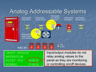
53.
Analog Addressable Systems
INPUTMODULE
WATERFLOW
POINT 004 A=N/A
NORMAL F=N/A
Input/output modules do not
relay analog values to the
panel as they are monitoring
or controlling on/off devices.
Addressable
Relay Module
(Fan Shutdown)
Addressable
Heat Sensor
Addressable
Smoke Sensor
Addressable
Input Module
(Waterflow)
001 002
003
004
005
Addressable
Pull Station
Addressable
Smoke Sensor
006
10K
EOLR
NAC #1
54.
Analog Addressable
Features
Ananalog addressable control panel is capable of
several enhanced features not available on conventional,
and some addressable systems.
Drift Compensation / Maintenance Alert
Adjustable Detector Sensitivity
Day/Night Detector Sensitivity Adjustment
U.L. Calibrated Sensitivity Test Instrument
55.
Drift Compensation
Driftcompensation is the process by which an analog
addressable control panel automatically adjusts an
analog detectors alarm threshold to compensate for
contaminants such as dust.
This ensures the detector maintains a consistent
sensitivity level, helping to avoid false alarms due to
dirty detectors.
56.
Maintenance Alert
Driftcompensation occurs until it is nearing a point
where it can no longer compensate and remain within
U.L. requirements. This point is called “Maintenance
Alert”
Some systems handle a maintenance alert condition as
a trouble while others flag the condition only, and
continue to operate normally.
57.
Calibration Trouble
Adetector in a maintenance alert condition will
eventually go into calibration trouble if not serviced.
A detector in calibration trouble is not functioning
correctly and requires service immediately.
58.
Adjustable (Day/Night)
Sensitivity
Inorder to allow for varying environmental conditions or
to provide quicker detection, analog systems typically
allow you to change the sensitivity of a detector within a
range of U.L. tolerances.
This is typically made user friendly by giving the installer
choices such as high-medium-low.
59.
Adjustable (Day/Night)
Sensitivity
Bychanging a detectors sensitivity you are instructing
the panel to adjust its alarm threshold (analog) value up
or down accordingly.
Some systems allow this sensitivity adjustment to
happen automatically on a day/night schedule.
60.
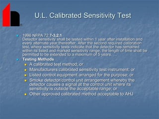
U.L. Calibrated SensitivityTest
1996 NFPA 72 7-3.2.1
Detector sensitivity shall be tested within 1 year after installation and
every alternate year thereafter. After the second required calibration
test, where sensitivity tests indicate that the detector has remained
within its listed and marked sensitivity range, the length of time shall be
permitted to be extended to a maximum of 5 years. …
Testing Methods
A calibrated test method; or
Manufacturers calibrated sensitivity test instrument; or
Listed control equipment arranged for the purpose; or
Smoke detector/control unit arrangement whereby the
detector causes a signal at the control unit where its
sensitivity is outside the acceptable range; or
Other approved calibrated method acceptable to AHJ
61.
Analog addressablecontrol panels are UL listed for the
purpose of performing the calibrated sensitivity testing
internally.
A printout from the panel is usually available to provide
evidence to the AHJ that the test was performed.
U.L. Calibrated Sensitivity Test
62.
Communication Protocols
Eachmanufacturer of (analog) addressable fire alarm systems
utilize a unique communications protocol on the SLC loop to
communicate between the control panel and the addressable
devices.
Most protocols are developed by detector manufacturers.
Many manufacturers subtly modify standard protocols, developed by
detector manufacturers, to provide a proprietary environment for
their equipment & distributors.
63.
Communication Protocols
Manyof the panels installation requirements and
operational parameters are based on the communication
protocol used.
SLC Loop Length
SLC Loop Wire Type
SLC Loop Communications Speed
SLC Loop Alarm Response Time
Communication protocols can be broken down into two
categories.
Non-Digital
Digital
64.
Comparing Protocols
To takea closer look at
communication protocols we
can look at non-digital and
digital SLC Loops through an
oscilloscope.
Addressable
Relay Module
(Fan Shutdown)
Addressable
Heat Detector
Addressable
Smoke Detector
Addressable
Input Module
(Waterflow)
001 002
003
004
005
Addressable
Pull Station
Addressable
Smoke Detector
006
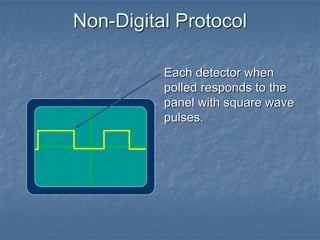
Non-Digital Protocol
The panelreads these
square wave pulses and
determines the values by
measuring the length
(time) of each.
67.
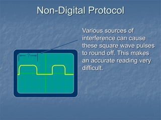
Non-Digital Protocol
Various sourcesof
interference can cause
these square wave pulses
to round off. This makes
an accurate reading very
difficult.
?
68.
Non-Digital Protocol
Most manufacturersthat
utilize a non-digital
protocol will specify
special requirements
such as twisted or
shielded wire to
counteract this problem.
?
69.
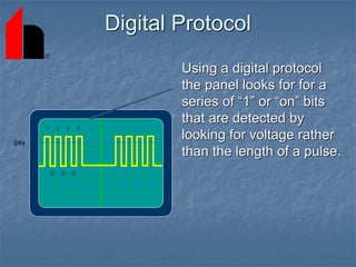
Digital Protocol
Using adigital protocol
the panel looks for for a
series of “1” or “on” bits
that are detected by
looking for voltage rather
than the length of a pulse.
0
1 1 1 1
0 0
24v
70.
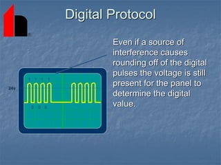
Digital Protocol
Even ifa source of
interference causes
rounding off of the digital
pulses the voltage is still
present for the panel to
determine the digital
value.
0
1 1 1 1
0 0
24v
71.
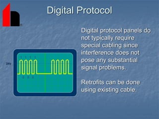
Digital Protocol
Digital protocolpanels do
not typically require
special cabling since
interference does not
pose any substantial
signal problems.
Retrofits can be done
using existing cable.
0
1 1 1 1
0 0
24v
72.
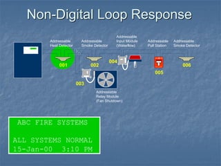
Non-digital Loop Response
When an alarm occurs on many non-digital protocol
systems, some panels must continue polling until it
reaches the alarming device, before an alarm is initiated.
Larger systems with hundreds of points can cause
delays initiating an alarm.
73.
Non-Digital Loop Response
FIRE
FIRE
SILENTKNIGHT
Addressable
Heat Detector
Addressable
Smoke Detector
Addressable
Input Module
(Waterflow)
001 002
003
004
005
Addressable
Pull Station
Addressable
Smoke Detector
006
ABC FIRE SYSTEMS
ALL SYSTEMS NORMAL
15-Jan-00 3:10 PM
Addressable
Relay Module
(Fan Shutdown)
74.
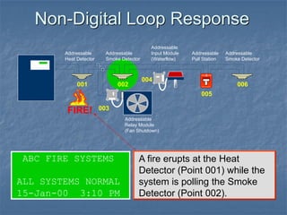
Non-Digital Loop Response
ABCFIRE SYSTEMS
ALL SYSTEMS NORMAL
15-Jan-00 3:10 PM
FIRE!
A fire erupts at the Heat
Detector (Point 001) while the
system is polling the Smoke
Detector (Point 002).
FIRE
FIRE
SILENT KNIGHT
Addressable
Heat Detector
Addressable
Smoke Detector
Addressable
Input Module
(Waterflow)
001 002
003
004
005
Addressable
Pull Station
Addressable
Smoke Detector
006
Addressable
Relay Module
(Fan Shutdown)
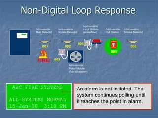
75.
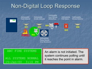
Non-Digital Loop Response
ABCFIRE SYSTEMS
ALL SYSTEMS NORMAL
15-Jan-00 3:10 PM
An alarm is not initiated. The
system continues polling until
it reaches the point in alarm.
FIRE
FIRE
SILENT KNIGHT
Addressable
Heat Detector
Addressable
Smoke Detector
Addressable
Input Module
(Waterflow)
001 002
003
004
005
Addressable
Pull Station
Addressable
Smoke Detector
006
FIRE!
Addressable
Relay Module
(Fan Shutdown)
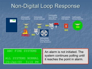
76.
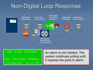
Non-Digital Loop Response
ABCFIRE SYSTEMS
ALL SYSTEMS NORMAL
15-Jan-00 3:10 PM
An alarm is not initiated. The
system continues polling until
it reaches the point in alarm.
FIRE
FIRE
SILENT KNIGHT
Addressable
Heat Detector
Addressable
Smoke Detector
Addressable
Input Module
(Waterflow)
001 002
003
004
005
Addressable
Pull Station
Addressable
Smoke Detector
006
FIRE!
Addressable
Relay Module
(Fan Shutdown)
77.
Non-Digital Loop Response
ABCFIRE SYSTEMS
ALL SYSTEMS NORMAL
15-Jan-00 3:10 PM
An alarm is not initiated. The
system continues polling until
it reaches the point in alarm.
FIRE
FIRE
SILENT KNIGHT
Addressable
Heat Detector
Addressable
Smoke Detector
Addressable
Input Module
(Waterflow)
001 002
003
004
005
Addressable
Pull Station
Addressable
Smoke Detector
006
FIRE!
Addressable
Relay Module
(Fan Shutdown)
78.
Non-Digital Loop Response
ABCFIRE SYSTEMS
ALL SYSTEMS NORMAL
15-Jan-00 3:10 PM
An alarm is not initiated. The
system continues polling until
it reaches the point in alarm.
FIRE
FIRE
SILENT KNIGHT
Addressable
Heat Detector
Addressable
Smoke Detector
Addressable
Input Module
(Waterflow)
001 002
003
004
005
Addressable
Pull Station
Addressable
Smoke Detector
006
FIRE!
Addressable
Relay Module
(Fan Shutdown)
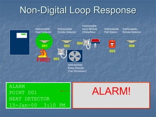
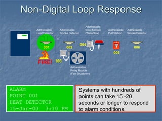
Non-Digital Loop Response
ALARM
POINT001
HEAT DETECTOR
15-Jan-00 3:10 PM
Systems with hundreds of
points can take 15 -20
seconds or longer to respond
to alarm conditions.
FIRE
FIRE
SILENT KNIGHT
Addressable
Relay Module
(Fan Shutdown)
Addressable
Heat Detector
Addressable
Smoke Detector
Addressable
Input Module
(Waterflow)
001 002
003
004
005
Addressable
Pull Station
Addressable
Smoke Detector
006
FIRE!
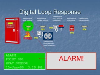
81.
Digital Loop Response
When an alarm occurs on most digital protocol systems,
an interrupt request from the device sensing the alarm
interrupts the polling sequence to immediately handle
the alarm.
Systems with hundreds of points will respond to
alarms in the same amount of time that they would to
smaller systems with very few points.
82.
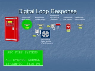
Digital Loop Response
ABCFIRE SYSTEMS
ALL SYSTEMS NORMAL
15-Jan-00 3:10 PM
Addressable
Heat Sensor
Addressable
Smoke Sensor
001 002
003
004
005
Addressable
Pull Station
Addressable
Smoke Sensor
006
Addressable
Relay Module
(Fan Shutdown)
Addressable
Input Module
(Waterflow)
83.
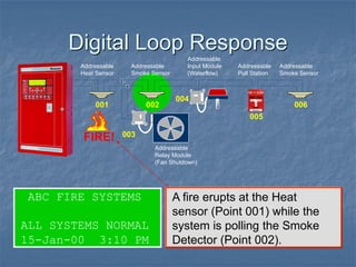
Digital Loop Response
ABCFIRE SYSTEMS
ALL SYSTEMS NORMAL
15-Jan-00 3:10 PM
A fire erupts at the Heat
sensor (Point 001) while the
system is polling the Smoke
Detector (Point 002).
Addressable
Heat Sensor
Addressable
Smoke Sensor
001 002
003
004
005
Addressable
Pull Station
Addressable
Smoke Sensor
006
FIRE!
Addressable
Relay Module
(Fan Shutdown)
Addressable
Input Module
(Waterflow)
84.
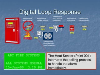
Digital Loop Response
ABCFIRE SYSTEMS
ALL SYSTEMS NORMAL
15-Jan-00 3:10 PM
The Heat Sensor (Point 001)
interrupts the polling process
to handle the alarm
immediately.
Addressable
Heat Sensor
Addressable
Smoke Sensor
001 002
003
004
005
Addressable
Pull Station
Addressable
Smoke Sensor
006
FIRE!
Addressable
Relay Module
(Fan Shutdown)
Addressable
Input Module
(Waterflow)