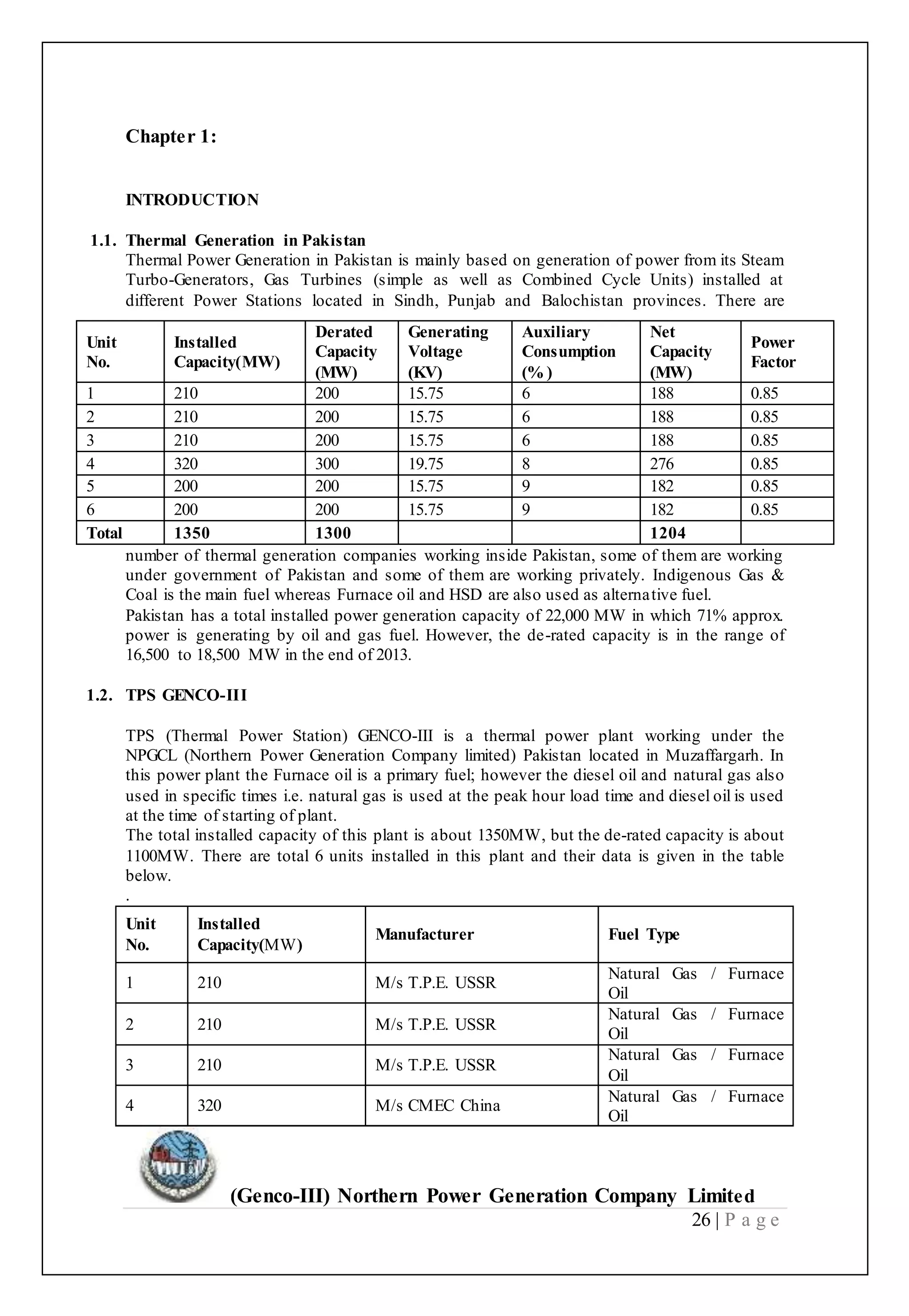
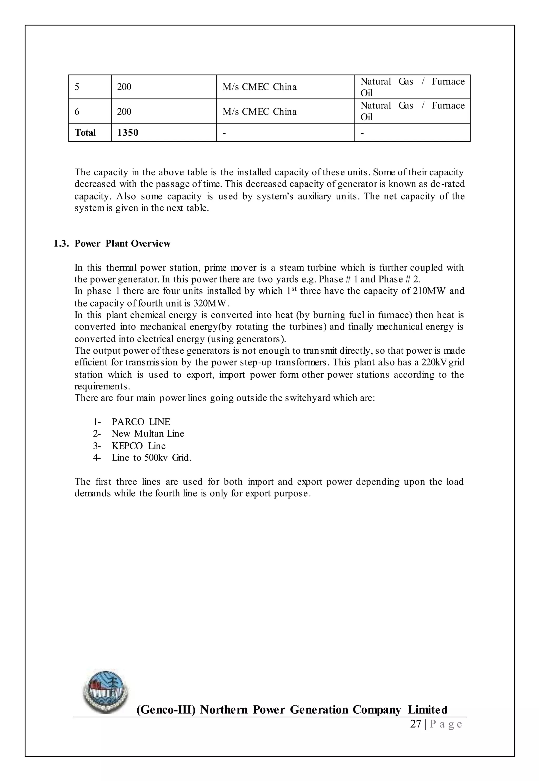
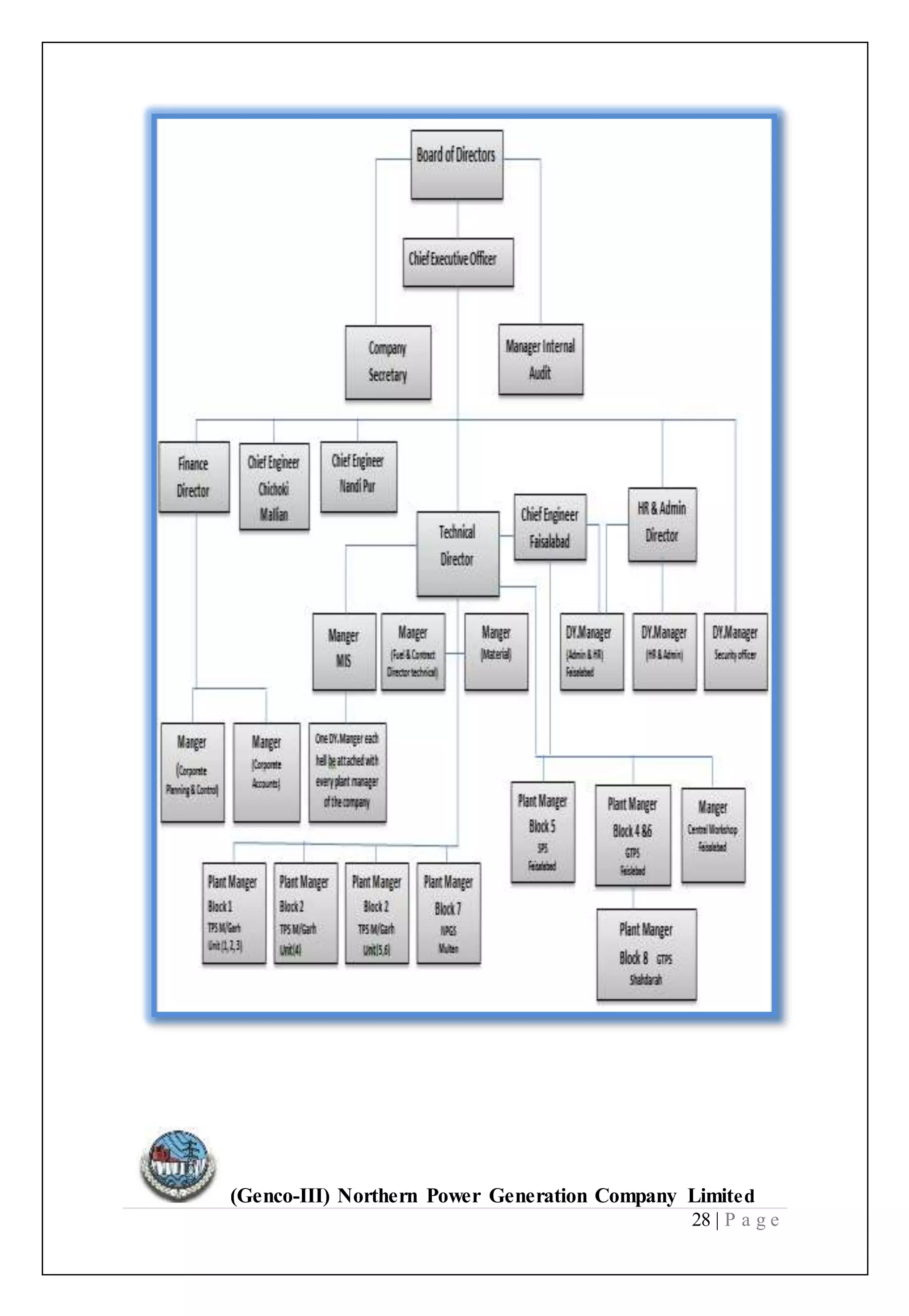
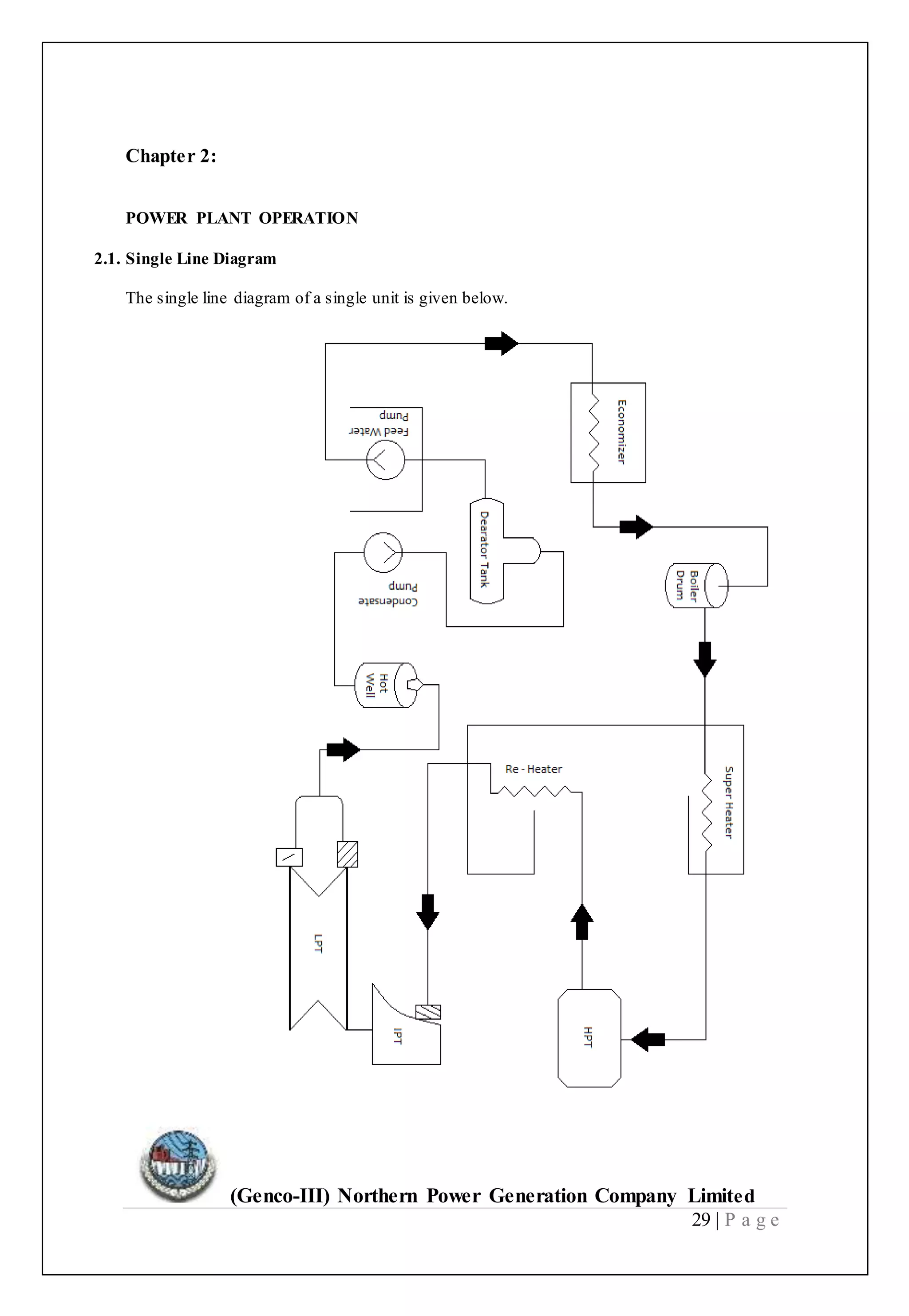
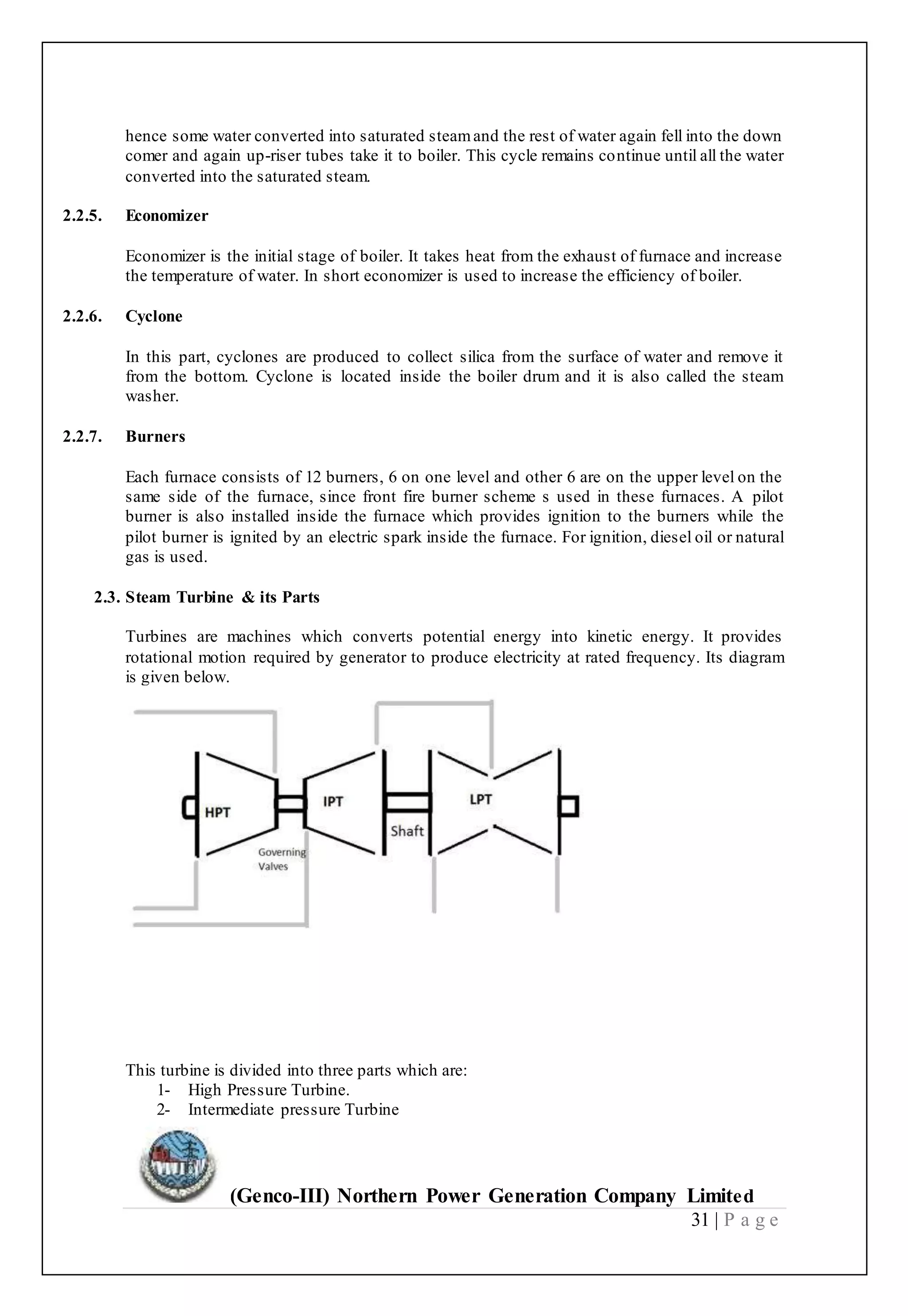
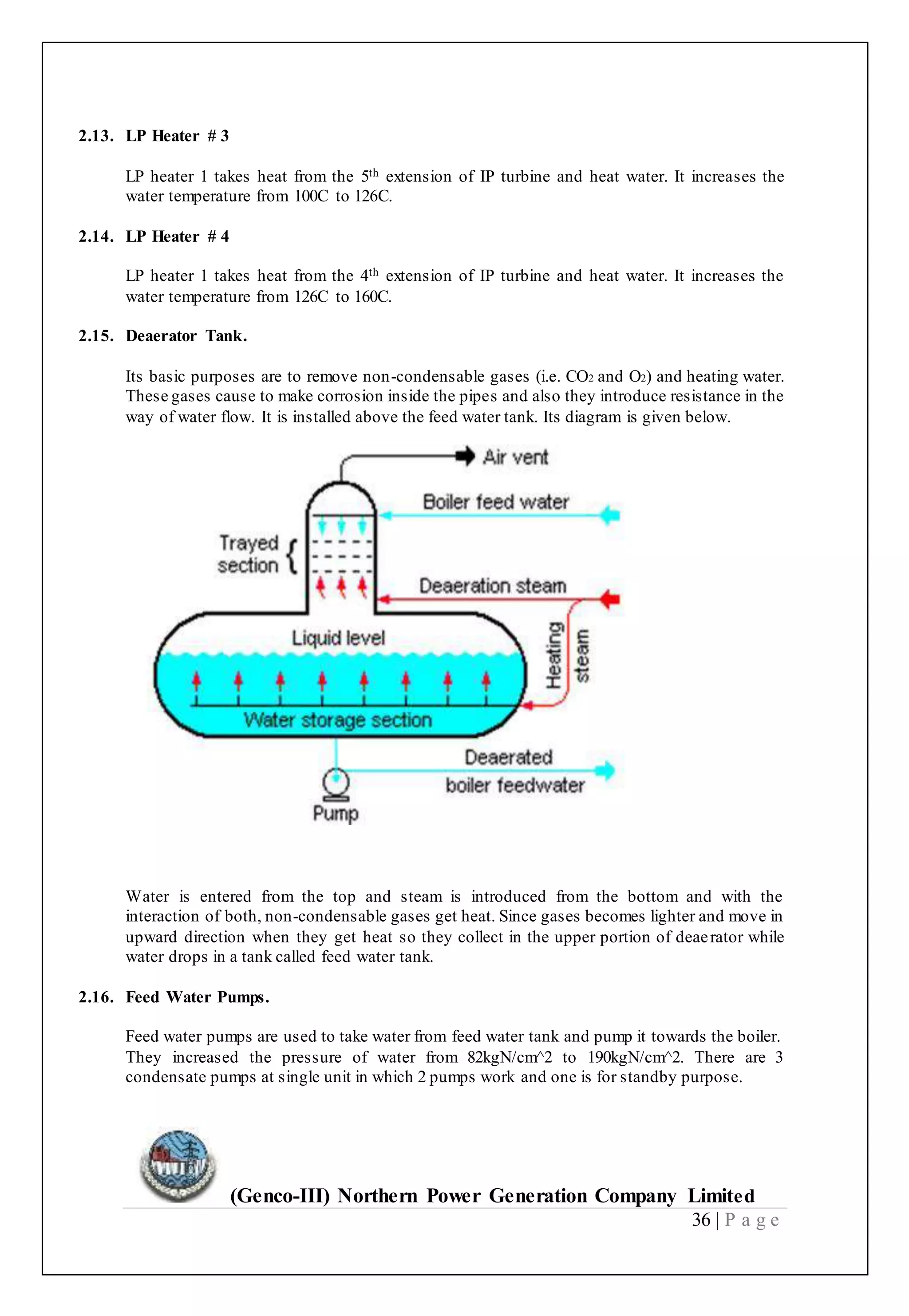
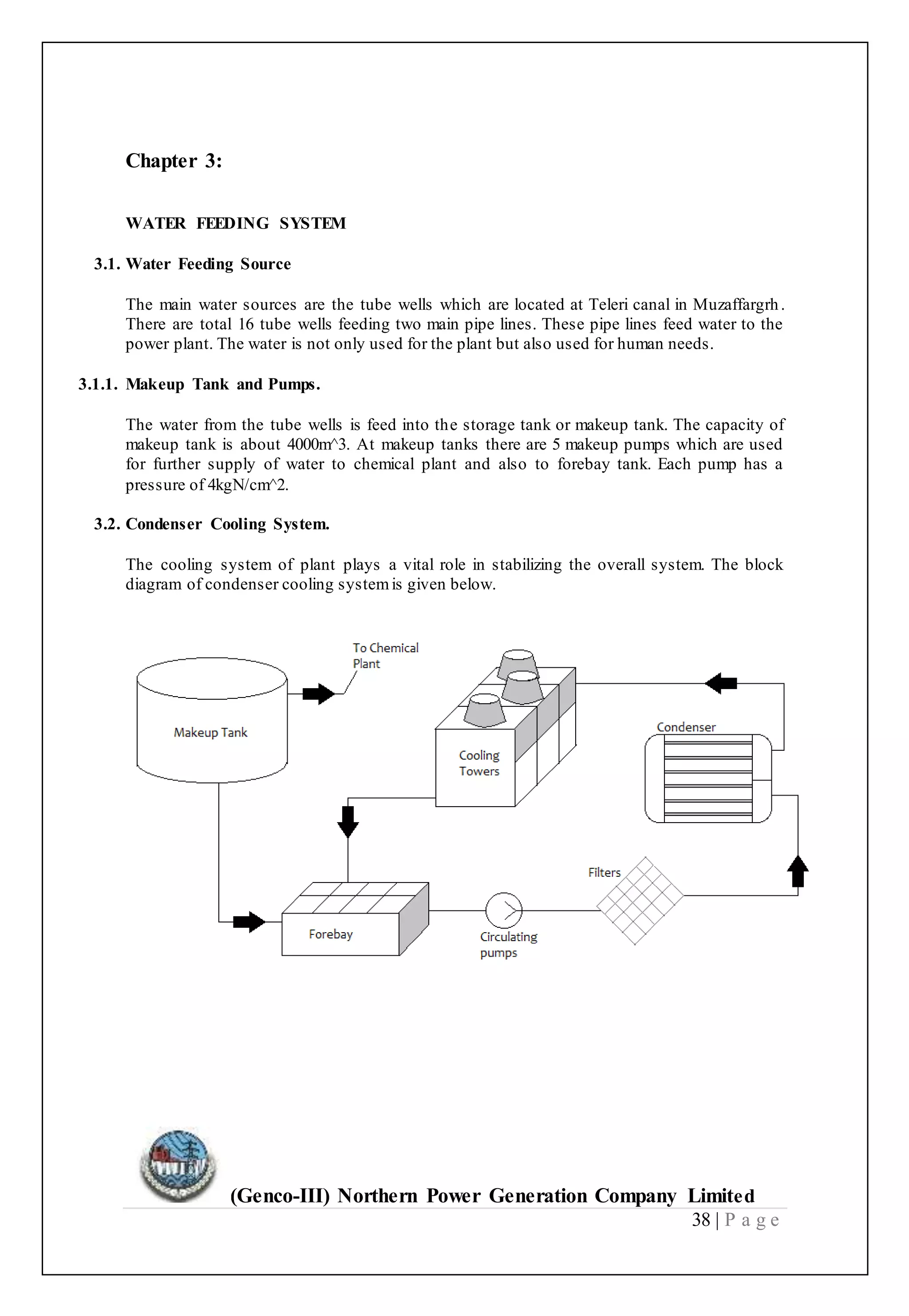
(Genco-III) Northern Power Generation Company Limited
1 | P a g e
(Genco-III) Northern Power Generation Company Limited
2 | P a g e
(Genco-III) Northern Power Generation Company Limited
3 | P a g e
PREFACE
Practice makes a man perfect and practical knowledge is essential in order to
introducing with the practical life. Theoretical knowledge is not such
important without with combination of practical knowledge. It is the part of
its academic curriculum to do internship of BSc Electrical Engineering &
Technology student to various Engineering concerns with view to allowing
students to get opportunity to acquire practical and professional knowledge.
This report was also assigned the task of preparing the term paper, the topic
was “(Genco-III) Northern Power Generation Company Limited”. To adjust
myself in such a large organization was not an easy task, but by the grace of
Almighty Allah aids my internship in a befitting manner and I learned a lot
about the overall generation company. The report has been prepared after
careful observation of the all component of organization. This report is a
thorough essence of my rigorous studies which I undergone through in a
period of four months in a generation company. I have exclusively studied and
observed the operations/ functioning of the company and tried my best to
abreast myself with all the dimensions of the generation company. It was a
great experience to work there and contribute handsomely in the process of
appraising its pros and cons and feeling to be a significant part of the
company. I am thankful to all those who helped me in one-way or the other
and guided me in the preparation and compilation of this report in a
presentable fashion.
(Genco-III) Northern Power Generation Company Limited
4 | P a g e
ACKNOWLEDGEMENT
Success and achievement is possible only through hard work, determination and
strong will. We are grateful to ALLMIGHTY ALLAH who gave me the strength to
think, plan and act accordingly which make us possible to complete my internship.
Though it is a literary tradition to acknowledge the contribution and help by different
people and organization in the completion of an internship, but as a matter of fact
some words cannot express our gratitude to the various helping hands. It is very
difficult to appreciate each and every person for his contribution, but there is a
standing contribution of our advisor Sir Muhammad Arshad Bhatti sb, who was
there with us at the time we needed him and without his guidelines it would be
difficult for us to complete this internship successfully.
Thanks to all
(Genco-III) Northern Power Generation Company Limited
5 | P a g e
DEDICATION
At first dedicating this work to Almighty ALLAH, without his
mercy and sympathy I was not able to accomplish this work,
Almighty ALLAH gave me power and confidence to done my
internship and also HOLY PROPHET HAZARAT MUHAMMAD
(Peace Be upon Him) who is a light for humanity. I also dedicate
this work to my lovely parents with deepest gratitude whose love
and prayers have always been a source of strength for me.
(Genco-III) Northern Power Generation Company Limited
6 | P a g e
TABLE OF CONTENTS
Contents Numbers
1. Executive Summary--------------------------------------------------------------------------------------4
2. Introduction of Wapda-----------------------------------------------------------------------------------5
3. Pakistan Electric Power Company---------------------------------------------------------------------7
4. Thermal Generation---------------------------------------------------------------------------------------10
5. Background-------------------------------------------------------------------------------------------------16
6. Introduction-------------------------------------------------------------------------------------------------17
7. Objectives---------------------------------------------------------------------------------------------------18
8. Goals----------------------------------------------------------------------------------------------------------20
9. Chapter 1:
Introduction----------------------------------------------------------------21
1.1. Thermal Generation InPakistan -----------------------------------------------------------21
1.2. TPSGenco-III-----------------------------------------------------------------------------------22
1.3. Power Plant Overview-----------------------------------------------------------------------23
10. Chapter 2:
Power Plant Operation------------------------------------------------------24
2.1. Single Line Diagram----------------------------------------------------------------------------
----------24
2.2. Boiler & its Parts-------------------------------------------------------------------------------
--------25
2.3. Steam Turbine & its Parts---------------------------------------------------------------------
--------26
2.4. Condenser---------------------------------------------------------------------------------------
--------28
2.5. Hot Well-----------------------------------------------------------------------------------------
--------29
2.6. Make-upWater Connection-------------------------------------------------------------------
--------29
2.7. Condensate pump------------------------------------------------------------------------------
---------29
2.8. Main Ejector------------------------------------------------------------------------------------
---------29
2.9. Vent SteamCondenser------------------------------------------------------------------------
--------30
(Genco-III) Northern Power Generation Company Limited
7 | P a g e
2.10. LP Heater# 1-----------------------------------------------------------------------------------
---------30
2.11. GlandSteam Condenser-----------------------------------------------------------------------
---------30
2.12. LP Heater # 2----------------------------------------------------------------------------------
---------30
2.13. LP Heater # 3----------------------------------------------------------------------------------
---------30
2.14. LP Heater # 4----------------------------------------------------------------------------------
---------30
2.15. DeaeratorTank--------------------------------------------------------------------------------
---------30
2.16. FeedWater Pumps----------------------------------------------------------------------------
---------31
2.17. HP Heater# 5---------------------------------------------------------------------------------
---------31
2.18. HP Heater# 6---------------------------------------------------------------------------------
---------31
2.19. HP Heater# 7---------------------------------------------------------------------------------
---------31
11. Chapter 3:
Water Feeding System-----------------------------------------------------------------------------------------
---32
3.1. Water Feeding Source------------------------------------------------------------------------------------------
--------32
3.2. Condenser Cooling System-----------------------------------------------------------------------------------------
----32
3.3. Water Purification System------------------------------------------------------------------------------------------
----33
12. Chapter 4:
Power Plant Fuel------------------------------------------------------------------------------------------------------
--36
4.1. Fuil Oil Facilities---------------------------------------------------------------------------------------------------
-------36
4.2. Oil Feeding System----------------------------------------------------------------------------------------------------
----36
4.3. Diesel Oil Tanks------------------------------------------------------------------------------------------------------
----37
4.4. Fuel Requirements----------------------------------------------------------------------------------------------------
----37
13. Chapter 5:
(Genco-III) Northern Power Generation Company Limited
8 | P a g e
Electricity Generation-----------------------------------------------------------------------------------------------
--38
5.1. Main Generators--------------------------------------------------------------------------------------------------
------38
5.2. Excitation Control System--------------------------------------------------------------------------------------------
---38
5.3. Main Transformers----------------------------------------------------------------------------------------------------
---43
5.4. Auxiliary Transformers-----------.-----------------------------------------------------------------------------------
---47
5.5. Main Auxiliary Equipments------------------------------------------------------------------------------------------
---48
5.6. Auxiliary Control System--------------------------------------------------------------------------------------------
----49
14. Chapter 6:
220kv Switch Yard-------------------------------------------------------------------------------------------------
--49
6.1. Busbar System-----------------------------------------------------------------------------------------------------
-----49
6.2. Isolators-----------------------------------------------------------------------------------------------------------------
---50
6.3. Circuit Breakers -------------------------------------------------------------------------------------------------------
---51
6.4. PT (potential transformer) -------------------------------------------------------------------------------------------
---53
6.5. CT (current Transformer) --------------------------------------------------------------------------------------------
---54
6.6. Surge Arrestors--------------------------------------------------------------------------------------------------------
---55
6.7. Control System--------------------------------------------------------------------------------------------------------
---56
15. Swot Analyses ------------------------------------------------------------------------------------------------------------------------------------------------
-----62
16. Recommendations-------------------------------------------------------------------------------------------------------------------------------------------
-----67
17. Conclusion-----------------------------------------------------------------------------------------------------------------------------------------------------------
-----68
(Genco-III) Northern Power Generation Company Limited
9 | P a g e
EXECUTIVE SUMMARY
According to internship requirement, I passed Four (4) Months at Genco fromFeb 1st,2016 to
May 31,2016. This was so much learning period for me. This internship report is about
Thermal Power Station Muzaffargarh also named as GENCO_III. In GENCO_III ,there are
total 6 units in which Phase-I consists of 3 units of 210MW each and Phase-II consists of 2
units of 210MW each and a separate unit namely unit-IV having a capacity of 320MW.So a
total of 1,370MW capacity of GENCO-III. The generators installed are all furnace oil
generators consisting of a steam turbine and having water tube Boiler. In this report, different
protections of generator and transformers are discussed. The circuit Breakers and their types
and relays and the role of instrument transformer are discussed. The importance of
switchyard is given in detail.
In this report I give introduction history of the Genco. In this report I did SWOT analyses,
financial analyses, projects of Genco and projects which I did in Genco. This project gives to
me as assignment which is also helpful for the organization. So I give some recommendations
and conclusion at the end.
(Genco-III) Northern Power Generation Company Limited
10 | P a g e
INTRODUCTION OF WAPDA
WAPDA, the Pakistan Water and Power Development Authority, was created in 1958 as a
Semi-Autonomous Body for the purpose of coordinating and giving a unified direction to the
development of schemes in Water and Power Sectors, which were previously being dealt
with, by the respective Electricity and Irrigation Department of the Provinces.
Since October 2007, WAPDA has been bifurcated into two distinct entities i.e. WAPDA and
Pakistan Electric Power Company (PEPCO). WAPDA is responsible for water and
hydropower development whereas PEPCO is vested with the responsibility of thermal power
generation, transmission, distribution and billing. There is an independent Chairman and MD
(PEPCO) replacing Chairman WAPDA and Member (Power) who was previously holding the
additional charges of these posts.
 WAPDA is now fully responsible for the development of Hydel Power and Water
Sector Projects.
 PEPCO has been fully empowered and is responsible for the management of all the
affairs of corporatized nine Distribution Companies (DISCOs), four Generation
Companies (GENCOs) and a National Transmission Dispatch Company (NTDC).
These companies are working under independent Board of Directors (Chairman and
some Directors are from Private Sectors).
 The Companies are administratively autonomous and leading to financial autonomy
by restructuring their balance sheets by bringing their equity position to at least 20
percent, required to meet the prudential regulations and to facilitate financing from
commercial sector (approved by ECC).
 The Loan Liability Transfer Agreements (LLTA) has been signed with Corporate
Entities and execution of loan transfer is complete.
 All Entities have the physical possessions of all their operational assets.
 On 24th Feb. 2007 Ministry of Water & Power notified NEPRA approved Tariff for
all Distribution Companies replacing unified WAPDA Tariff.
(Genco-III) Northern Power Generation Company Limited
11 | P a g e
 Legal Agreements such as Business Transfer Agreements, Operation Development
Agreement, Energy Supply Agreement, Business Supplementary Agreement and
Fuel Supply Agreement etc. were executed between WAPDA and Corporate Entities
to facilitate commercial operations.
 Regulatory instruments like Grid Code, Distribution Codes, Performance Standard
for Distribution Companies and Transmission Companies were drafted and got
approved from in 2007.
 All major lenders gave their consent for transfer of their loan from WAPDA to
Corporate Entities, thus 326 loan assumption agreements were signed amongst
respective Companies, WAPDA and EAD (Economic Affairs Division) GOP.
 CPPA is established under the coverage of NTDC for payments from DISCOs to
IPPs, GENCOs and NTDC. Ultimately, it will function independently under Federal
Govt. and all forthcoming IPPs will be under CPPA.
The Charter of Duties of WAPDA is to investigate, plan and execute schemes for the
following fields:
 Generation, Transmission and Distribution of Power.
 Irrigation, Water Supply and Drainage.
 Prevention of Water logging and Reclamation of Waterlogged and Saline Lands.
 Flood Management.
 Inland Navigation.
The Authority comprises of a Chairman and three (3) Members working through a Secretary.
WAPDA is one of the largest employers of human resources in Pakistan. It has 150,000
employees, which make it 2nd largest organization of Pakistan, after Pakistan army. Over the
years WAPDA has built-up a reservoir of Technical know-how and expertise which has made
it a modern and progressive organization.
WATER WING
In 1959, WAPDA was created to undertake the task of investigating, planning and
executing schemes for irrigation, drainage, prevention of water logging and reclamation
(Genco-III) Northern Power Generation Company Limited
12 | P a g e
of saline land as an autonomous body responsible for integrated development of water
and power resources in Pakistan. The organization was also entrusted with the work of
implementing Indus Basin Settlement Plan signed between India and Pakistan in 1960
to develop replacement works for management of river water and irrigation system.
Since then it has been engaged in building water development projects which include
extensive research and investigation to augment country's water resources.
POWER WING
Power Wing is currently headed by
Member (Power) PEPCO.
PAKISTAN ELECTRIC POWER COMPANY
The Pakistan Electric Power Company (Private) Limited (PEPCO) has been entrusted the
task of managing the transition of WAPDA from a bureaucratic structure to a corporate,
commercially viable and productive entity. It is a mammoth task and progress in the initial
months was rather slow, but one should keep in mind that responsibility is enormous and
transition is a long drawn process.
Before going into further details of the restructuring program, it is necessary to understand
the shift in the GoP policy. The GoP, in line with its Strategic Plan of 1992 approved by the
(Genco-III) Northern Power Generation Company Limited
13 | P a g e
cabinet committee, had decided to restructure the entire power sector in the country
 De-regulation of power sector
 Promotion of IPPs
 Restructuring of WAPDA
 Privatization of select corporate entities
The factors responsible for the shift in policies were: generation capacity could not be
increased to meet demand; WAPDA's growth caused inefficiencies, 'demand suppression' and
high tariff policy, proliferated theft. All these factors, over the years, adversely affected
WAPDA's financial condition. As part of this program WAPDA's functions under its Water
Wing and Power Wing were to be segregated. It was previously envisaged that all power
generation, hydel as well as thermal, would be corporatized. However, later on it was decided
that the hydel generation should remain part of the Water Wing or the remaining WAPDA.
PEPCO has prepared the conceptual framework and is following a comprehensive strategy
whereby WAPDA's vertical-monolithic Power Wing has been restructured into twelve (12)
distinct autonomous entities under Companies Ordinance 1984. These are: three generation,
one transmission and eight distribution corporate entities
The restructuring program of WAPDA's Power Wing is based on the new strategic policies of
the GOP and endorsed and supported by the donor institutions. The aimof this transition is to
install corporate and business culture through: adopting of good business practices, enhancing
productivity and efficiency, including customer orientation and service culture, improving
quality of services setting performance targets, reducing costs, theft and wastage. This will be
based on extensive use of information technology, management information systems,
monitoring and prudent decision making.
It has been decided that some of the functions currently being performed by WAPDA will
continue to remain with WAPDA/GoP in the largest interest of the country.
These are:
 Hydel development
 Hydel operation
(Genco-III) Northern Power Generation Company Limited
14 | P a g e
It was also decided that some of the common facilities, being previously shared by the two
wings and by various departments within the power wing, should be segregated. These would
initially remain with WAPDA unless transferred to any other particular corporatized entity.
These facilities include hospitals, schools, training facilities etc.
ACCOMPLISHMENTS
Major accomplishments to-date is as follows:
Operationalized Pakistan Electric Power Company (PEPCO) as a Private limited management
company owned by Government of Pakistan (GOP) to steer, manage and oversee the
corporatization/commercialization reforms program.
Formed fourteen (14) Corporate Entities as following:
 Four (4) Thermal Power Generation Companies (GENCOs)
 One (1) National Transmission & Power Dispatch Company (NTDC)
 Nine (9) Distribution Companies (DISCOs)
 Constituted Board of Directors of the corporate entities with the induction of
Directors from the private sector and PEPCO to utilize their experience for
formulation of effective corporate policies.
 Executed Legal agreements such as Business Transfer Agreements (BTA), Operation
and Development Agreement (ODA), Electricity Supply Agreements (ESA), Bulk
Supply Agreements (BSA) and Fuel Supply Agreements (FSA) between WAPDA
and corporate entities for autonomous commercial operation.
 Transfer of WAPDA staff to the respective corporate entities (Manpower Transition
Program Phase-I completed). Phase II is scheduled for completion by June, 2000.
 Obtained Federal Tax Exemptions for the corporate entities for Capital Value Tax,
Income tax and Wealth Tax.
 Obtained consent of most of the creditors.
 Prepared, reviewed, approved and adopted opening Balance Sheets of the corporate
entities as of 30-06-1998.

(Genco-III) Northern Power Generation Company Limited
15 | P a g e
 Privatization schedule for Faisalabad Electric Supply Company (FESCO) finalized &
sent to the Privatization Commission of Pakistan
 Investment Plans for Distribution Power System Rehabilitation prepared and
finalized by the Distribution companies
 Financial Restructuring of WAPDA approved by GOP
 Filed applications by all Power Distribution Companies (DISCOs) for obtaining
License from National Electric Power Regulatory Authority (NEPRA). Public
hearing by NEPRA for processing of applications of Lahore Electric Power Supply
Company (LESCO) and Gujranwala Electric Power Company (GEPCO) completed
 Submitted proposal to GOP for Price consideration to be paid or settled by GOP with
WAPDA so that share of the corporate entities owned by WAPDA can be transferred
in the name of GOP.

THERMAL GENERATION
PEPCO's Thermal Power Generation is mainly based on generation of power from its Steam
Turbo-Generators, Gas Turbines (simple as well as Combined Cycle Units) installed at
different Power Stations located in Sindh, Punjab and Baluchistan provinces. Indigenous Gas
& Coal is the main fuel whereas Furnace oil and HSD are also used as alternative fuel. .
As per Government of Pakistan policy all thermal power generation has been restructured and
four corporatized companies namely Jamshoro Power Generation Company Limited
(GENCO-1) head quarter at Jamshoro district Dadu near Hyderabad Sindh, Central Power
Generation Company Limited (GENCO-2) head quarter at Guddu district Jacobabad Sindh
and Northern Power Generation Company Limited (GENCO-3) headquarters at Muzaffargarh
(Genco-III) Northern Power Generation Company Limited
16 | P a g e
and Lakhra Power Generation Company Limited (GENCO-IV) at Khanote (Sindh) have been
formed and registered. Functioning of GENCOs has commenced.
Structural formation of all four GENCOs is as under:
JPCL
(GENCO-1)
CPGCL
(GENCO-2)
NPGCL
(GENCO-3)
LPGCL
(GENCO-4)
TPS Jamshoro TPS Guddu TPS Muzaffargarh FBC Lakhra
GTPS Kotri TPS Quetta NGPS Multan
TPS GUDDU
a. Location
Thermal Power Station Guddu is situated on the right bank of River Indus near Guddu
barrage, 10 Km from Kashmore in district Jacobabad (Sindh). It is about 60 Km away from
Sadiqabad and about 160 Km from Sukkur. It is a confluence of three provinces, i.e. Sindh,
Punjab and Baluchistan.
b. Fuel (Gas & F. Oil) Supplies
The existing daily gas allocation is 285 MMCFD, (from Kandhkot = 115 MMCFD, Sui = 40
MMCFD Mari=90 MMCFD & Tullow= 40 MMCFD). Daily requirement of gas is about 310
MMCFD and in this way there is short fall of about 25 MMCFD. Furnace Oil is also used to
meet-with short fall of Gas quota. Furnace oil is received through Railway Wagons and Tank
Lorries from Karachi.
TPS QUETTA
a. Location
This Power Station is situated at Quetta.
b. Fuel (Gas) Supplies
Natural gas is the main fuel being used for combustion as and when available basis. Company
under the new management (PEPCO) is trying to make an agreement with the gas company
regarding firm gas supply.
TPS MUZAFFARGARH
(Genco-III) Northern Power Generation Company Limited
17 | P a g e
a. Location
TPS Muzaffargarh is located in the middle of the country between the River Indus and River
Chenab, 2.5 Km to North-West of Muzaffargarh Town in District Muzaffargarh. The nearest
Airport facility is at Multan at a distance of 45 Km North-East of Muzaffargarh.
b. Fuel
Dual fuel combustion provision (Gas & Furnace Oil) has been made for all the machines.
Furnace oil is transported through Railway Wagons and tank Lorries.
NGPS MULTAN
a. Location
Power Station is located at Piranghaib about one Km towards North from Piranghaib Railway
station and at a distance of 10 Km from Multan city towards East.
b. Fuel
Dual fuel combustion provision (Gas & Furnace Oil) has been made for all the machines. 15
MMCFD gas is allocated and the short fall is met with by furnace oil firing.
SPS FAISALABAD
a. Location
This Power Station is situated at about 10 Km from Faisalabad city on Faisalabad-
Sheikhupura road. Nishatabad railway station is 04 Km in the West and Rakh branch canal
flows close to the power station in the East.
b. Fuel
Dual fuel combustion provision (Gas & Furnace Oil) has been made for all the machines.
Requirement of Gas on 70% load factor is about 22 MMCFD.
GTPS FAISALABAD
a. Location
This Power Station is situated (adjoining SPS) at about 10 Km from Faisalabad city on
Faisalabad-Sheikhupura road. Nishatabad railway station is 04 Km in the West and Rakh
branch canal flows close to the power station in the East.
(Genco-III) Northern Power Generation Company Limited
18 | P a g e
b. Fuel
Dual fuel combustion provision (Gas & HSD Oil) has been made for all the machines.
GTPS SHAHDARA
a.Location
This Power Station is situated at Shahdara on right bank of river Ravi Lahore.
b. Fuel (Gas) Supplies
Natural gas is the main fuel being used for combustion as and when available basis. Company
under the new management (PEPCO) is trying to make an agreement with the gas company
regarding firm gas supply.
FBC LAKHRA
a. Location
The Lakhra Power Station is located near Manzoor-abad/Khanote in the District of Dadu
(Sindh) on the right bank of mighty Indus River. Hyderabad city is about 46 Km in North -
East and Karachi is about 200 Km South-West of the Power Plant. The Power Station can be
readily approached from North and South by the connecting highways.
b. Fuel
All the three units are based on Coal, which is being recovered by primitive underground
mining method from Lakhra coal mines, 25 Km from Lakhra Power Station.
The detail of three GENCOs showing Power stations, number of units installed, capacity,
make, year of commissioning and fuel used is given below in table-1, 2, 3&4.
(Genco-III) Northern Power Generation Company Limited
19 | P a g e
To make Pakistan Power Sector customer
friendly, efficient, able and responsive in
meeting tee electric energy requirements of
industry, business and domestic customers,
and move to an energy sufficient model from
the current energy deficient scenario, on
commercially viable and sustainable basis, in
order to support the high growth economy
and to meet the government's objective of
"Power for All".
• VISION
To fullyenable the reformand restructuringof the Pakistan Power
Sector and to transform the fourteen(14) Corporate entities(CE's)
into autonomousand commerciallyviable enterprises,thru
inductionof effective corporate management,bestbusinessand
utilitypractices, and well-engineeredsystems,andbridge the ever
growing supply-demandgap,so as to meetcustomerselectric
energyrequirementona sustainable and environmentallyfriendly
basis, thru bestutilizationof resources,inan efficient,ethical and
customer friendlymanner,with responsibilitytothe community and
the Nation.
• MISSION
(Genco-III) Northern Power Generation Company Limited
20 | P a g e
GENERATION COMPANIES
 Jamshoro Power Company Limited (JPCL) GENCO I
 Central Power Generation Company Limited (CPGCL) GENCO II
 Northern Power Generation Company Limited (NPGCL) GENCO III
 Lakhra Power Generation Company Limited (LPGCL) GENCO IV
ONE TRANSMISSION COMPANY
 National transmission & power dispatch company (NTDC)
EIGHT DISTRIBUTION CORPORATE ENTITIES
1. LAHORE ELECTRIC SUPPLY COMPANY LIMITED (LESCO)
2. GUJRANWALA ELECTRIC POWER COMPANY (GEPCO)
3. FAISALABAD ELECTRIC SUPPLY COMPANY (FESCO)
4. ISLAMABAD ELECTRIC SUPPLY COMPANY (IESCO)
5. MULTAN ELECTRIC POWER COMPANY (MEPCO)
6. PESHAWAR ELECTRIC SUPPLY COMPANY (PESCO)
7. HYDERABAD ELECTRIC SUPPLY COMPANY LIMITED (HESCO)
8. QUETTA ELECTRIC SUPPLY COMPANY (QESCO)
(GENCO-III) NORTHERN POWER GENERATION COMPANY LIMITED
MISSIONSTATEMENT
Our mission is tobring the assurance of energytoour customer, with world class
quality and commitment for satisfactionas we inour quest forexcellence
(Genco-III) Northern Power Generation Company Limited
21 | P a g e
BACKGROUND
Northern Power Generation Company Limited owns and operates thermal power generation
facilities located at Muzaffargarh, Multan and Faisalabad. Installed capacity of the generating
assets is 1,921 MW, which has declined over the years to dependable capacity of 1,169 MW.
Complex pattern of internal and external factors constrain operating and financial
performance of the company. The company has been operating with a negative bottom line,
which has jeopardized sustainability.
Government of Pakistan aims to address the country’s power sector issues by implementing
Power Sector Reform Program. As part of the program the public sector thermal power
generation companies (GENCOs), including NPGCL were required to develop and implement
Business Plans to effectively respond to constraints and obstacles to satisfactory performance.
(Genco-III) Northern Power Generation Company Limited
22 | P a g e
INTRODUCTION
This thermal power station is situated in Multan division’s district Muzaffargarh. In 1985
Gulam Ishaq Khan make an agreement with Russia for the establishment of the power station.
Initially this Project was documented for Multan. But due to certain reasons like availability
of land, cost etc. This project shifted to Muzaffargarh by the name of Multan II. Initially three
units were established in Muzaffargarh, called phase 1. These are also known as Russian
units. These units are operated with Oil & Gas. The each unit is of 210 M.W. capacities.
China establishes their units to meet the need/demand of electricity. These units are also 210
M. Watt.
China has also established a unit called unit #4 witches has the capacity of 320 M. watt. The
unit #4 is fully computerized. All its functionality is handled through computerized programs.
About 1500 people are working in this organization including both technical & non-technical.
To make this project Economic District Muzaffargarh was select. Other Reasons for this
location is that there is no thermal house in this Area at that time the Area like Multan
Division and D.G Khan lies at center of Pakistan approximately. The selection of this location
may be due to safety reason in war conditions.
Pakistan Water and Power Development Authority (WAPDA) is an integrated utility in
Pakistan. WAPDA is responsible for the development of Hydel Power and Water
Sector Projects in Pakistan. WAPDA operates through- Power wing and Water wing, it is
engaged in the generation, transmission and distribution of power. In addition, it also manages
irrigation, water supply and drainage system in the country. Further, it is also responsible for
prevention of water logging and reclamation of waterlogged and saline lands.
The Pakistan Water and Power Development Authority (WAPDA) was established through
an act of parliament in February 1958 for integrated and rapid development and
maintenance of water and power resources of the Country. This includes
controlling soil salinity and water logging to rehabilitate the affected land in
order to strengthen the predominantly agricultural economy of the country. As
per the charter, amended in March 1959 to transfer the existing electricity
(Genco-III) Northern Power Generation Company Limited
23 | P a g e
departments from the federating units to it, WAPDA has been assigned the duties
of investigation, planning and execution of projects and schemes for:
 Generation, Transmission and distribution of power,
 Irrigation, water supply and drainage,
 Prevention of water logging and reclamation of saline land,
 Flood control and Inland navigation.
Under the later on developments, vis-à-vis the “energy policy 1994”, setting up of
thermal power generation projects was shifted to the private sector. Similarly, as a result of re
structuring of the power wing, the utility part was corporatized into independent companies.
This shift from convergence to divergence gave birth to 13 entities to operate in different
zones. These are national transmission and Dispatch Company (ntdc), four thermal
power generation companies (gencos) and eight distribution companies (discos).
The present status of these companies is of corporate public limited entities
under the Umbrella of EPCO, ultimately to go privatized as planned. The
residual Power Wing is therefore now responsible for major hydro-electric power
projects and schemes in operation.
(Genco-III) Northern Power Generation Company Limited
24 | P a g e
OBJECTIVES
Pakistan Electric Power Company (PEPCO) unveiled new face of Pakistan's power
sector with the crisis management objectives to improve the efficiency of the power
sector and to meet customers' electric energy requirements on a sustainable and
environment friendly basis. The specific objectives of PEPCO are:
• Stop load shedding,
• Revamping of generation units and to improve
customer services and
Objectives
• Constructing new grid stations,
• Reducing line losses; minimizing tripping
and theft control,
Objectives
• Development of an integrated automated power
planning systemfor generation, transmission and
distribution to ensure systemstability, fault
isolation and upgrade relying, metering and
tripping systemat NTDC as well as Discos level.
Objectives
(Genco-III) Northern Power Generation Company Limited
25 | P a g e
GOALS
The following power projects are in pipeline and will be included in GENCO III after their
commissioning.
G
O
A
L
S
* 425MW combine cycle dual fuel (furnace + HSD) at
Nandipur. (3x 95MW gas turbine + 138MW steam unit)
* 320MW UAE gifted power plant at GTPS Faisalabad.
(5x16MW Fr5 gas turbines + 8x30MW Fr‐6 gas turbines)
* 525MW CCPP at Chichokimalian. (3x117MW gas
turbines + 175MW steam turbine
* Morale building and to create sense of belonging
amongst company employees.)
* Smooth and consistent flow/supply of electricity.
* Prompt restoration of disrupt electricity supply.
* Accurate and timely meter reading and billing.
* Provision of electricity connection in minimum time.
* Open door policy to facilitate our customers.
* Energy saving message dissemination.
* Creating positive image of Genco.
* Special concessions for quick and timely payment of
bill.
* Availability of stores to deal with emergencies.
* Feedback through customer services center.
* Create awareness amongst employees for adopting
* safety measures while working on lines.
* Take steps for welfare of company employees.
(Genco-III) Northern Power Generation Company Limited
26 | P a g e
Chapter 1:
INTRODUCTION
1.1. Thermal Generation in Pakistan
Thermal Power Generation in Pakistan is mainly based on generation of power from its Steam
Turbo-Generators, Gas Turbines (simple as well as Combined Cycle Units) installed at
different Power Stations located in Sindh, Punjab and Balochistan provinces. There are
number of thermal generation companies working inside Pakistan, some of them are working
under government of Pakistan and some of them are working privately. Indigenous Gas &
Coal is the main fuel whereas Furnace oil and HSD are also used as alternative fuel.
Pakistan has a total installed power generation capacity of 22,000 MW in which 71% approx.
power is generating by oil and gas fuel. However, the de-rated capacity is in the range of
16,500 to 18,500 MW in the end of 2013.
1.2. TPS GENCO-III
TPS (Thermal Power Station) GENCO-III is a thermal power plant working under the
NPGCL (Northern Power Generation Company limited) Pakistan located in Muzaffargarh. In
this power plant the Furnace oil is a primary fuel; however the diesel oil and natural gas also
used in specific times i.e. natural gas is used at the peak hour load time and diesel oil is used
at the time of starting of plant.
The total installed capacity of this plant is about 1350MW, but the de-rated capacity is about
1100MW. There are total 6 units installed in this plant and their data is given in the table
below.
.
Unit
No.
Installed
Capacity(MW)
Manufacturer Fuel Type
1 210 M/s T.P.E. USSR
Natural Gas / Furnace
Oil
2 210 M/s T.P.E. USSR
Natural Gas / Furnace
Oil
3 210 M/s T.P.E. USSR
Natural Gas / Furnace
Oil
4 320 M/s CMEC China
Natural Gas / Furnace
Oil
Unit
No.
Installed
Capacity(MW)
Derated
Capacity
(MW)
Generating
Voltage
(KV)
Auxiliary
Consumption
(% )
Net
Capacity
(MW)
Power
Factor
1 210 200 15.75 6 188 0.85
2 210 200 15.75 6 188 0.85
3 210 200 15.75 6 188 0.85
4 320 300 19.75 8 276 0.85
5 200 200 15.75 9 182 0.85
6 200 200 15.75 9 182 0.85
Total 1350 1300 1204
(Genco-III) Northern Power Generation Company Limited
27 | P a g e
5 200 M/s CMEC China
Natural Gas / Furnace
Oil
6 200 M/s CMEC China
Natural Gas / Furnace
Oil
Total 1350 - -
The capacity in the above table is the installed capacity of these units. Some of their capacity
decreased with the passage of time. This decreased capacity of generator is known as de-rated
capacity. Also some capacity is used by system’s auxiliary units. The net capacity of the
systemis given in the next table.
1.3. Power Plant Overview
In this thermal power station, prime mover is a steam turbine which is further coupled with
the power generator. In this power there are two yards e.g. Phase # 1 and Phase # 2.
In phase 1 there are four units installed by which 1st three have the capacity of 210MW and
the capacity of fourth unit is 320MW.
In this plant chemical energy is converted into heat (by burning fuel in furnace) then heat is
converted into mechanical energy(by rotating the turbines) and finally mechanical energy is
converted into electrical energy (using generators).
The output power of these generators is not enough to transmit directly, so that power is made
efficient for transmission by the power step-up transformers. This plant also has a 220kVgrid
station which is used to export, import power form other power stations according to the
requirements.
There are four main power lines going outside the switchyard which are:
1- PARCO LINE
2- New Multan Line
3- KEPCO Line
4- Line to 500kv Grid.
The first three lines are used for both import and export power depending upon the load
demands while the fourth line is only for export purpose.
(Genco-III) Northern Power Generation Company Limited
28 | P a g e
(Genco-III) Northern Power Generation Company Limited
29 | P a g e
Chapter 2:
POWER PLANT OPERATION
2.1. Single Line Diagram
The single line diagram of a single unit is given below.
(Genco-III) Northern Power Generation Company Limited
30 | P a g e
In the above diagram it has been shown that there is a cycle in which water converted into
steam, steam passes through turbine stages to rotate turbine shaft, after passes from turbine
stages this steam converted into water and then this water passes boiler to convert it into
steamagain.
2.2. Boiler & its Parts
A boiler is a closed vessel in which water or other fluid is heated. Generally the boiler has
three major parts which are:
1- Chimney
2- Furnace
3- Boiler Drum.
There are two major types of boiler which are given below.
1- Water Tubes Boiler
2- Fire Tubes Boiler
Here we will discuss the 1st type of boiler because in this plant water tubes boilers are used.
It consists of many parts some of its importants parts are given below.
2.2.1. Boiler Drum
It separates and stores water and steam. Pressure inside drumis 155kg/cm2 and temperature is
343oC. The steam inside the boiler drum is known as saturated steambecause it contain some
water vapors or in short it’s not a pure steam.
2.2.2. Super Heater
Super heater is the main heater of the furnace which has a temperature of 1600oC.The
saturated steam of boiler drum passes through super heater and its temperature increased to
540oC and has a pressure of 130kgN/cm^2.
There are four stages of super heater in the furnace which are:
1- Radiation Super Heater.
2- Pattern Super Heater.
3- Convection Super Heater.
4- Ceiling Super Heater.
The saturated steamenter from first stage and out from4th stage and becomes a live steam.
2.2.3. Down Comer
Down comer is part of boiler drum it’s placed below from the drumand it stores the hot water
which have not yet converted into saturated steam.
2.2.4. Up-Riser Tube
Up-riser tubes are also the part of boiler drum. They are used to take water fromdown comer
through pump and enter into the boiler. Here the water exposed to the high temperature and
(Genco-III) Northern Power Generation Company Limited
31 | P a g e
hence some water converted into saturated steamand the rest of water again fell into the down
comer and again up-riser tubes take it to boiler. This cycle remains continue until all the water
converted into the saturated steam.
2.2.5. Economizer
Economizer is the initial stage of boiler. It takes heat from the exhaust of furnace and increase
the temperature of water. In short economizer is used to increase the efficiency of boiler.
2.2.6. Cyclone
In this part, cyclones are produced to collect silica from the surface of water and remove it
from the bottom. Cyclone is located inside the boiler drum and it is also called the steam
washer.
2.2.7. Burners
Each furnace consists of 12 burners, 6 on one level and other 6 are on the upper level on the
same side of the furnace, since front fire burner scheme s used in these furnaces. A pilot
burner is also installed inside the furnace which provides ignition to the burners while the
pilot burner is ignited by an electric spark inside the furnace. For ignition, diesel oil or natural
gas is used.
2.3. Steam Turbine & its Parts
Turbines are machines which converts potential energy into kinetic energy. It provides
rotational motion required by generator to produce electricity at rated frequency. Its diagram
is given below.
This turbine is divided into three parts which are:
1- High Pressure Turbine.
2- Intermediate pressure Turbine
(Genco-III) Northern Power Generation Company Limited
32 | P a g e
3- Low pressure Turbine.
All these three parts are connected to singe shaft and making a tandemcompound. This shaft
is further coupled with the generator shaft. Inside the turbine there are so many blades some
of them are fixed and some are moveable, they are in curved shape so that steam can rotate
the moveable blades. There are total 29 stages of turbine.
1 stage = 2 fixed blades + 1 moveable blade.
1st stage of turbine is impulse turbine and rest stages are reaction turbine. Impulse stage is
used to drop the pressure and increase the velocity, so that high pressure can’t harmthe other
blades.
2.3.1. HPC Turbine
HPC stands for High Pressure Cylinder. It is the part where the steam from the super heater
enters to turbine. Here the temperature of live steam is 540C and very high pressure of
130kgN/cm^2. Therefore it is called high pressure turbine. It has 12 stages and 2 extensions.
2.3.2. Re-Heat Steam Cycle.
Steam after passing through the HP turbine drops its temperature to 332C and pressure to
28.1kgN/cm^2 and that steam can’t be feed to IP turbine because of water vapors which can
causes of damage the turbine blades. So, at this point the steamre-heated by the re-heater and
again its pressure raised to 540C but pressure doesn’t increase because of increasing the area
of pipe. The main reason for not increasing the pressure is to creating the pressure difference
between the entering point and exit point of HP turbine. If we increase the pressure then there
would be no pressure difference and hence steamwill stop to flow.
2.3.3. IPC Turbine
IPC (Intermediate pressure cylinder) also called IP turbine, because the pressure is very low.
It has 11 stages and all are reaction stages and has 4 extensions. The steam after passing
through the re-heater enters into the IP turbine and rotates its shaft. The IP turbine bears the
maximum load of generator.
2.3.4. LPC Turbine
LPC turbine is a low pressure turbine. Steam when passes through the IP turbine it
temperature fall down from 540C to 168C and pressure from 24.7kgN/m^2 to 1.23kgN/m^2.
Because of this low pressure this part of turbine is known is LP turbine. It has 6 stages and
only one extension.
2.3.5. Turbine Extensions
To increase the efficiency of turbine and reduce the cross section area of turbine there are
some extension pipes used to move out the steamfrom the cylinders of turbine.
Steam when enters into the turbine and move the blades then some of its portion lose the
temperature and remain at bottom of cylinder which causes to reduce turbine efficiency. So,
this portion of steam moves out from the cylinders by extension pipes and used to warm the
water.
(Genco-III) Northern Power Generation Company Limited
33 | P a g e
2.3.6. Turbine Capacity
As we know that the generator coupled with turbine shaft is of 210MW. So, the capacity of
turbine must be equal or more than 210MW. We know that there are three parts of this
turbine; each part is used to handle the different load. The turbine data is given in the table
below.
2.3.7. Speed Control System
Speed is an important factor of turbine. According to the requirement of the generator the
turbine must be able to rotate its shaft at 3000rpm on every load conditions.
To control the speed of turbine there are governing valves which are operated by hydraulic
pressure. They can be operated by both automatic and manual control. For automatic control
system there is a speed meter interfaced inside the turbine and also there is a servo motor
which controls the governing valves.
2.4. Condenser
A device or unit used to condense vapor into liquid by cooling it is known as condenser. Its
diagram is given below
Turbine Part No. of Stages No. of extensions
Capacity of Load
(MW)
HP – Turbine 12 2 60
IP – Turbine 11 4 100
LP - Turbine 6 1 50
(Genco-III) Northern Power Generation Company Limited
34 | P a g e
Steam (50oC and very low pressure), after rotating shaft in low pressure turbine reaches to
condenser. It is a tank with parallel tubes filled with raw water, coming from cooling towers.
Steam strikes with those pipes, loses its latent heat and condenses to water.
Condenser is the place where maximum heat loss occurs. Total no. of tubes in this condenser
is 16700 tubes. Each tube has 9m length and 28mm diameter length.
The condenser cooling surface area is 13180m^2 and its capacity is also 210MW.
2.5. Hot Well
When steam passes through the condenser then it becomes water and that water is stored in
the hot well. It is the also known as a storage tank the water in hot well of very low pressure
of 0.09kgN/cm^2 and low temperature of 45C.
2.6. Make-Up Water Connection
The pure water from the water-purification plant is added up at the outgoing path of hot well.
In a steamcycle the high pressure steampasses through different places and due to leakage at
somewhere, its quantity decreased and hence the quantity of pure water for the boiler is also
decreased so, the new water added up to fulfill the requirements of boiler.
2.7. Condensate Pump
Condensate pump is used to pick water from the hot well and pump it towards the deaerator
tank.
It increased the pressure of water from 0.09kgN/cm^2 to 16.2kgN/cm^2.
There are 3 condensate pumps at single unit in which 2 pumps work and one is for standby
purpose.
(Genco-III) Northern Power Generation Company Limited
35 | P a g e
2.8. Main Ejector
Main ejector is used to eject non-condensable from water by using vacuum, created due to
condensation. Two ejectors are installed. One is operational while other one is for backup use.
Its diagram is given below.
Maintaining vacuum at rated pressure is very necessary otherwise efficiency of boiler will
drop.
2.9. Vent Steam Condenser
It is used for warming the water. Its steam comes from turbine’s sealing. This is also used for
the air ventilation purposes because its steam contains some air. It rise the temperature from
48C to 50C.
2.10. LP Heater # 1
LP heater 1 takes heat from the 7th extension of LP turbine and heat water. It increases the
water temperature from 50C to 64C.
2.11. Gland Steam Condenser
Gland steam condenser performs the same task as vent steam condenser except for the air
ventilation because; its steam doesn’t contain air. It increases the water temperature from64C
to 68C.
2.12. LP Heater # 2
LP heater 2 takes heat from the 6th extension of IP turbine and heat water. It increases the
water temperature from 68C to 100C.
(Genco-III) Northern Power Generation Company Limited
36 | P a g e
2.13. LP Heater # 3
LP heater 1 takes heat from the 5th extension of IP turbine and heat water. It increases the
water temperature from 100C to 126C.
2.14. LP Heater # 4
LP heater 1 takes heat from the 4th extension of IP turbine and heat water. It increases the
water temperature from 126C to 160C.
2.15. Deaerator Tank.
Its basic purposes are to remove non-condensable gases (i.e. CO2 and O2) and heating water.
These gases cause to make corrosion inside the pipes and also they introduce resistance in the
way of water flow. It is installed above the feed water tank. Its diagram is given below.
Water is entered from the top and steam is introduced from the bottom and with the
interaction of both, non-condensable gases get heat. Since gases becomes lighter and move in
upward direction when they get heat so they collect in the upper portion of deaerator while
water drops in a tank called feed water tank.
2.16. Feed Water Pumps.
Feed water pumps are used to take water from feed water tank and pump it towards the boiler.
They increased the pressure of water from 82kgN/cm^2 to 190kgN/cm^2. There are 3
condensate pumps at single unit in which 2 pumps work and one is for standby purpose.
(Genco-III) Northern Power Generation Company Limited
37 | P a g e
2.17. HP Heater # 5
HP heater 5 takes heat from the 3rd extension of IP turbine and heat water. It increases the
water temperature from 167C to 182C.
2.18. HP Heater # 6
HP heater 6 takes heat from the 2nd extension of HP turbine and heat water. It increases the
water temperature from 182C to 220C.
2.19. HP Heater # 7
HP heater 7 takes heat from the 1st extension of HP turbine and heat water. It increases the
water temperature from 220C to 245C. Water after passing through this heater again goes
toward the boiler drum; where it again converted into the steam and then this cycle remains
continue.
(Genco-III) Northern Power Generation Company Limited
38 | P a g e
Chapter 3:
WATER FEEDING SYSTEM
3.1. Water Feeding Source
The main water sources are the tube wells which are located at Teleri canal in Muzaffargrh.
There are total 16 tube wells feeding two main pipe lines. These pipe lines feed water to the
power plant. The water is not only used for the plant but also used for human needs.
3.1.1. Makeup Tank and Pumps.
The water from the tube wells is feed into the storage tank or makeup tank. The capacity of
makeup tank is about 4000m^3. At makeup tanks there are 5 makeup pumps which are used
for further supply of water to chemical plant and also to forebay tank. Each pump has a
pressure of 4kgN/cm^2.
3.2. Condenser Cooling System.
The cooling system of plant plays a vital role in stabilizing the overall system. The block
diagram of condenser cooling systemis given below.
(Genco-III) Northern Power Generation Company Limited
39 | P a g e
3.2.1. Forebay Tank.
Forebay is place where the water is stored for condenser cooling. It stores a large amount of
water and also there are mechanical filters placed inside it which are used for filtration of
water.
Water filtration is necessary because the condenser tubes are too thin and impure water can
block them which results to decrease the condenser efficiency.
3.2.2. Circulating Pumps.
Circulating pumps are used to pick water from forebay tank and pump it towards the
condenser. There are 8 circulating pumps in which 6 pumps are for working and 2 are for
standby situation.
Each pump has a pressure of 17kgN/cm^2.
3.2.3. Cooling Towers
Cooling towers are used to maintain the temperature of water from the condenser.
There are 16 cooling towers for each unit and there are distributed into two sets. Each set has
eight fans. In these tower hot water is showering from the top and their fans suck air fromthe
bottomso, that the temperature of water decreased up to 6C.
3.3. Water Purification System.
For the making of steam and for the cooling of generators only the pure H2O water is used
because, impure particles in this water causes
1- Vibrations in the turbines and damage its blades.
2- Corrosion inside the pipes.
3- Electrical conductivity between the generator windings.
To purify the water from makeup tank there is a water treatment plant, where this water
passes through different stages to remove its impurities. The block diagram of this plant is
given on the next page. The raw water in this plant passes from6 different stages which are:
1- Mechanical Filters.
2- 1stStage of Cation Filter.
3- De-Gassifier.
4- Anion Filter.
5- 2nd Stage of Anion Filter.
6- Mixed Bed Filter.
Their description is given on the next page.
(Genco-III) Northern Power Generation Company Limited
40 | P a g e
3.3.1.
Mechanical Filters.
First of all, raw water enters in these filters. Four filters are installed for this purpose, in which
two of them are functional while other two are for stand-by use. Each tank has the capacity of
45T/h.
(Genco-III) Northern Power Generation Company Limited
41 | P a g e
3.3.2. Cation Filter # 1.
To removing the cation salts like ( Ca+2, Mg+2, Na+1 ),this water passes through cation filter,
where it interacts with hydrogen ions H+. These hydrogen ions replace the other cations from
their salts and removed in this stage. As we can see this equation below
MgSO4 + 2H+ Mg+ + H2SO4
3.3.3. De-Gassifier.
De- gassifier or de- carbonizer are used to remove CO2 gas from the water. For this purpose
there are two main chambers where water is showering from the top and air is entered form
the bottom by fans. This air interacts with the carbon ions in water and makes CO2 gas, which
moves out from the top side of chamber. And the water collected in the storage tank, located
below the chamber.
3.3.4. Anion Filter.
Water is sent to anion filter form decarbonized water tank, using pumps. There are four filters
in which one is used and other are for backup. Each filter has capacity of 90T/h. NaOH is
introduced in water to remove silica and other anions. As we can see the equation.
SiO2 + 2 NaOH→ Na2SiO3 + H2O.
3.3.5. Cation Filter # 2.
If any amount of cations remain in water even after cation filter, these filters remove those
cations. 98% pure H2SO4 is added in this filter to provide more H+ ions.
3.3.6. Mixed Bed Filter.
This is the last stage of water treatment procedure. It has the capability to remove both cations
and anions from water. They have a very good efficiency. This filter can operate for 3 to 4
hours if cation or anion filter do not work. In this filter water is passed through sulfuric acid
and sodiumhydro-oxide to remove the remaining cations and anions in the water.
3.3.7. Dematerialized Water Tank
After passing through the filters, water is sent to the demi water storage tank. This water has
no hardness and all other minerals values in tolerable ranges. Three tanks are available, each
with the capacity to store 2000 metric ton water. This water is supplied through pumps to the
makeup connection after hot well to fulfill the demand of unit.
(Genco-III) Northern Power Generation Company Limited
42 | P a g e
Chapter 4:
POWER PLANT FUEL
4.1. Fuel Oil Facilities.
Fuel is provided to the power plant by two major sources which are
1- Oil Tankers
2- Train he block diagram of oil feeding systemto power plant is given below.
Most of the furnace oil of power plant is provided by the oil tankers.
4.2. Oil Feeding System.
The block diagram of oil feeding systemto power plant is given below.
4.2.1. Decanting
The place where the oil is obtained from the oil tankers and trains is known as oil decanting.
It is like a deep pit under earth where fuel oil facilities discharge their oil.
4.2.2. Transfer Pumps.
Transfer pumps used to take oil from decanting pit and transfer it to the main oil storage tank.
There are four transfer pumps by which 3 are functional and 1 is for backup.
4.2.3. Storage Tanks.
(Genco-III) Northern Power Generation Company Limited
43 | P a g e
There are 6 oil storage tanks are installed in the plant for phase-I, each has 20,000m3 capacity.
To enhance the efficiency of the plant, small amount of MgO is added as a catalyst in the oil
which improves combustion process.
4.2.4. Recirculation pumps.
Recirculation pumps are used to keep oil in warm conditions the take oil from storage tanks
and pass it from heater and then again feed it back to the storage tank.
4.2.5. Recirculation heaters.
Recirculation heaters are used to keep storage tank’s oil in warm condition. In short they
increase the oil efficiency because; combustion of warm oil becomes very easy. Their
temperature is above 80C.
4.2.6. 1st Lift Pump.
1st lift pump is used to take oil from storge tank and passes it through the main steam heater
and it also provide the suction to the 2nd lift pump. There are four 1st lift pumps are used and
their discharge pressure is about 7-8kgN/cm^2.
4.2.7. Main Heater.
Main heaters are used to warm the oil for combustion process. They use steam for heating
purpose. Here the temperature of oil rises to 110C which is necessary for combustion because,
if the temperature of furnace oil below 100C then it can’t combust properly.
4.2.8. 2nd lift Pump.
2nd lift pump is used to take warm oil from main heaters and transfer it to the boiler side.
There are 4 2nd lift pumps are used and their discharge pressure is about 40-45kgN/cm^2.
4.3. Diesel oil Tanks.
There are two diesel oil tanks at phase # 1. Each has a capacity to store 1000T diesel oil.
Power plant uses diesel oil for few hours at the starting time.
(Genco-III) Northern Power Generation Company Limited
44 | P a g e
4.4. Fuel Requirements.
Fuel requirements for the power plant are given in the table below.
Unit No. FO requirement/ day (MT) NG requirement/ day (MMSCFD)
1,2 & 3 3600 114
4 1800 50-70
5 & 6 2400 76
(Genco-III) Northern Power Generation Company Limited
45 | P a g e
Chapter 5:
ELECTRICITY GENERATION.
5.1. Main Generators.
Generator is a machine which converts mechanical energy into electrical energy. It has a
moving part called rotor and a stationary part called stator. A generator has two types of
windings
1- Field winding
2- Armature winding.
In this power plant turbo generators are used because of single shaft of turbine and generator.
Main generator is a three phase two pole synchronous generator its specifications are given
below.
Sr. No. Generator’s Parameters Values
1 Part no. TBB – 220 – 2E
2 Active Power 210MW
3 Reactive power 133MVAr
4 Apparent Power 247MVA
5 Power Factor 0.85
6 Frequency 50Hz
7 RPM 3000
8 Stator Voltage 15.75kV
9 Stator Current (Rated) 9056A
10 Rotor Voltage 303V (D.C)
11 Rotor Current (Rated) 2330A (D.C)
12 No. of Poles 2
5.1.1. Generator’s Cooling System.
There is a proper cooling systemfor the generator winding. Its stator winding is cooled by the
distillate water and rotor winding is cooled by the pure hydrogen gas.
The quality of distillate water is maintained by chemical lab testing and its resistance is
maintained to above 200 (kilo-ohm/cm) so that it can’t conduct between the stator windings.
Its flow rate inside the generator is about 30T/h, which is accomplished by 2 pumps
(1 operational and other standby) and their discharge pressure is about 6.5kgN/cm^2.
For rotor cooling hydrogen gas is used because its flow rate is higher than water and it has a
unique property of rapid cooling than water. Its pressure is maintained to 4kgN/cm^2 and its
oil is used for its sealing which has a pressure of 4.7kgN/cm^2.
(Genco-III) Northern Power Generation Company Limited
46 | P a g e
5.1.2. Generator Protection System.
There is a protection system for the generator to prevent it fromany kind of damage in case of
any kind of fault occur. Generally there are three major faults occur which are:
1- Stator Faults
2- Rotor/Excitation Faults.
3- System Faults.
These protections are given below.
A. Stator Faults:
i. Phase short circuit protection:
In case of short-circuits between phases in the stator winding or between the generator
terminals, the machine must quickly be disconnected from the network and brought to a
complete shutdown in order to limit the damage.
Differential relays are used for this purpose. Longitudinal differential protection is us ed which
means rapid and selective relay protection of feeder and interconnectors based on a direct
comparison of the currents at the end point of cables.
ii. Earth fault Protection:
Common practice is to earth the generator neutral through a resistor, which gives a maximum
earth-fault current of 5-10 A. Short-circuits between the stator winding in the slots and the
stator core are the most common electrical fault in generators. The fault is normally initiated
by mechanical or thermal damage to the insulating material or the anti- corona paint on a
stator coil. Inter-turn faults, which normally are difficult to detect, will quickly develop into
an earth-fault and will be tripped by the stator earth-fault protection.
iii. Phase inter-turn fault protection:
Inter-turn faults can only occur in case of double earth-faults or as a result of severe
mechanical damage on the stator end winding. Due tothe difficulties in obtaining a reliable
and secure inter-turn protection, it is in most cases omitted. It is assumed that the inter-turn
fault, first of all, will lead to a single phase earth fault at the faulty spot, and the machine will
then be tripped by the earth-fault relay within 0.3 – 0.4 s.
iv. Thermal overload protection:
Overloads up to 1.4 times the rated current are not normally detected by the impedance or
over current protection. Sustained overloads within this range are usually supervised by
temperature monitors (resistance elements) embedded at various points in the stator slots.
B. Rotor/Excitation faults:
i. Loss of excitation protection:
(Genco-III) Northern Power Generation Company Limited
47 | P a g e
A complete loss-of-excitation may occur as a result of:
• Unintentional opening of the field breaker
• An open circuit or a short circuit of the main field
• A fault in the automatic voltage regulator (AVR), with the result that the field current is
reduced to zero.
When a generator with sufficient active load loose the field current, it goes out of
synchronism and starts to run asynchronously at a speed higher than the system, absorbing
reactive power (VAR) for its excitation from the system.
ii. Rotor earth fault Protection:
The rotor circuit can be exposed to abnormal mechanicalor thermal stresses due to vibrations,
excessive currents or choked cooling medium flow etc. This may result in a breakdown of the
insulation between the field winding and the rotor iron at one point where the stress has been
too high. The field circuit is normally kept insulated from earth. A single earth-fault in the
field winding or its associated circuits, therefore, gives rise to a negligible fault current and
does not represent any immediate danger. If, however, a second earth-fault occurs, heavy fault
current and severe mechanical unbalance may quickly arise and lead to serious damage. It is
essential, therefore, that any occurrence of insulation failure is discovered and that the
machine is taken out of service as soon as possible. Normally, the machine is tripped after a
short time delay.
iii. Bearing insulation/ shaft current protection:
Emf is developed in the shaft of the generators due to the magnetic dissimilarities in the
armature field. The emf normally contains a large amount of harmonics. If the bearing
pedestals at each side of the generator are earthed the induced emf will be impressed across
the thin oil-films of the bearings. A breakdown of the oil-film insulation in the two bearings
can give rise to heavy bearing currents due to the very small resistance of the shaft and the
external circuit. Consequently, the bearing base farthest from the prime mover is usually
insulated from earth and the insulation supervised by a suitable relay. To prevent the rotor and
the shaft from being electro-statically charged, the shaft of turbo-generators is usually
grounded via a slip-ring on the prime mover side.
C. System Faults:
i. Stator over load protection:
When load currents exceed the rated values there is a future risk that conductors and
insulation will be damaged due to overheating. To avoid this damage, stator over load
protection is kept in mind.
24
ii. Reverse power protection:
Its basic purpose is to protect prime mover. If the driving torque becomes less than the total
losses in the generator and the prime mover, the generator starts to work as a synchronous
compensator, taking the necessary active power fromthe network. In case of steamturbines, a
(Genco-III) Northern Power Generation Company Limited
48 | P a g e
reduction of the steam flow reduces the cooling effect on the turbine blades and overheating
may occur.
iii. Unbalance load/ negative sequence current protection:
The negative-sequence current produces an additional ampere-turn wave which rotates
backwards, hence it moves relatively to the rotor at twice the synchronous speed. The double
frequency, eddy currents induced in the rotor may cause excessive heating, primarily in the
surface of cylindrical rotors and in the damper winding of rotors with relevant poles.
iv. Accidental stator energizing/Dead machine protection:
Three-phase energization of a generator which is at standstill or on turning gear causes it to
behave and accelerate
Similarly, to an induction motor and high currents develop in the rotor during the period it is
accelerating. Although the rotor may be thermally damaged from excessive high currents, the
time to damage will be on the order of a few seconds. However, of more critical concern is
the bearing, which can be damaged in a fraction of a second due to low oil pressure.
Therefore, it is essential that high speed clearing be provided. For the offset mho type of loss-
of-excitation relay, operation is marginal when setting and relay tolerances are considered,
and the operate time would, in any case, be in the order of hundreds of milliseconds. The
back-up impedance relay and the reverse power relay would operate with a typical time delay
of 1-2 or 10-20s respectively. For big and important machines, fast protection against
inadvertent energization should be included in the protective scheme.
v. Under frequency protection:
In practice, prolonged generator operation at low frequency can only occur when a machine
with its local load is separated from the rest of the network. The necessity of under-frequency
protection has to be evaluated from knowledge of the network and the characteristics of the
turbine regulator.
vi. Over frequency protection:
Steam turbines are also sensitive to over-speed. For large steam turbine generators, over-
frequency protection with one or two frequency stages should be included. The protection will
provide a back-up function for the speed monitoring device.
vii. Over voltage protection:
If circuit breaker of the generator trips when it is working at its full load and rated power
factor a subsequent increase in terminal voltage is occurs which is controlled by AVR.
However, if AVR is faulty the severe over voltage conditions will be reached. With this rise
in voltage a simultaneous over-speeding should occur. An instantaneous high set voltage relay
can be included to trip the generator quickly in case of excessive over-voltages following a
sudden loss of load and generator over-speeding.
(Genco-III) Northern Power Generation Company Limited
49 | P a g e
viii. Under voltage protection:
Generally, the rating of one machine is small in comparison with an interconnected system. It
is, therefore, not possible for one machine to cause an appreciable rise in the terminal voltage
as long as it is connected to the system. Increasing the field excitation, for example owing to a
fault in the AVR, merely increases the reactive Mvar output, which may, ultimately, lead to
tripping of the machine by the impedance relay or the V/Hz relay. In some cases, e.g. with
peak-load generators and synchronous condensers, which are often called upon to work at
their maximum capability, a maximum excitation limiter is often installed. This prevents the
rotor field current and the reactive output power from exceeding the design limits.
25
ix. Over excitation protection:
The excitation flux in the core of the generator and connected power transformers is directly
proportional to the ratio of voltage to frequency (V/Hz) on the terminals of the equipment.
The losses due to eddy currents and hysteresis cause the temperature rise, increasing
proportion to the level of excitation. The core laminations can withstand relatively high over
fluxing without becoming excessively heated, but unlamented metallic parts can experience
severe heating in a short time. The risk of over excitation is, obviously, largest during periods
when the frequency is below rated value. The proper way of protection is to use a relay which
measures the ratio between voltage and current (V/Hz) relay.
x. Out-of-step operation/ loss of synchronism protection:
Loss of synchronism may be harmful to a rotating machine if not detected already after a few
pole slips and the machine is disconnected from the network. Detection may be by counting
over-current pulses or by watching the load apparent impedance. The impedance locus would
typically perform circles in the impedance plane, from low impedance (180 degrees out-of-
step) to high impedance.
5.2. Excitation Control System.
In the power houses main generators are excited by the outer supply, so that their output
voltages can be controlled according to the systemdemands. In this power plant there is a vast
excitation control system. Its diagram is given on the next page.
According to the excitation diagram there is a main exciter for the main generator’s excitation
the basic principle of the excitation is that in the starting of generator its exciter takes DC
Battery’s supply for the rotor field then the exciter’s stator voltages converted into DC by
passing through thyrestors and then DC battery supply disconnected and DC supply fromthe
thyrestors connected, in this way the exciter is self excited through its own stator supply.
After that the stator voltage of main exciter given to the main thyrestors to convert theminto
DC and those DC voltages are provided to the main generator’s rotor field. Hence the Main
generator is excited by the main exciter and the out voltages about 15.75kVare taken fromthe
stator.
The description of previous diagram is given below.
(Genco-III) Northern Power Generation Company Limited
50 | P a g e
5.2.1. Main Exciter.
For each Main generator there is a main Exciter for its excitation. It provides DC to the rotor
of the generator to produce electromagnet. Exciter itself is an AC generator. Its output is
transfer to the thyristor converters. They convert AC into DC and send it to the rotor of
generator. Rotor of exciter also required DC. This DC is provided by batteries for 3 seconds
and later DC comes from thyristor converters. Rotors of generator and exciter are rotates on
the same shaft, rotated by turbines. Unit # 1, 2 & 3 has exciters with specifications:
1- Active Power = 1010 kW,
2- P.F. = 0.46,
3- Speed = 3000RPM,
4- f = 50Hz,
5- Vstator=520V,
6- Istator=2400A,
7- Irotor=154A.
5.2.2. Thyristors.
Thyristor is the semi-conductor device used to convert AC Power into DC Power. They are
also used to regulating AC voltages by cutting the AC waveformshape by different angles.
5.2.3. CT’s & PT’s.
CT (Current Transformer) and PT (Potential Transformer) are the instrumentation
transformers which are used to measure the current and voltage respectively.
5.2.4. AEC or AVR.
AEC (Automatic Excitation control) is a device which measures the system voltages and
compares them with the output voltages of generator and then adjust the excitation voltages of
generator so that the generator’s voltages and systemvoltages can be synchronized.
It is also called the AVR (Automatic Voltage regulator).
5.2.5. Manual Control System.
In case of any fault if the AEC or AVR stop working then there is a manual control systemto
adjust the generator’s output according to the systemvoltages. The manual control systemis
quit difficult to use.
5.3. Main Transformers.
A transformer is a static machine/device that transforms an alternating current (AC) input
voltage into a higher or lower AC output voltage. Transformers are not designed to raise or
lower direct current (DC) voltages. A LPT (Large Power Transformer) is a large, custom-built
(Genco-III) Northern Power Generation Company Limited
51 | P a g e
piece of equipment that is a critical component of the bulk transmission grid. Its diagram is
given below.
Figure illustrates a standard core-type LPT. Although LPTs come in a wide variety of sizes
and configurations, they consist of two main active parts:
1- The core, which is made of high permeability, grain-oriented, silicon electrical steel,
layered in pieces.
2- Windings, which are made of copper conductors wound around the core, providing
electrical input and output.
5.3.1. Transformer Winding.
In this power plant main transformer is an auto transformer with tap changers. Its winding
diagram is given below.
(Genco-III) Northern Power Generation Company Limited
52 | P a g e
These are three phase star connection transformers with tertiary winding in delta cconnection.
The tertiary winding is for the safety of transformer in case of line fault occur.
5.3.2. Transformer Cooling System.
The cooling of these transformers is done by the oil cooling system. These transformers use
the OFAF (Oil Forced Air Forced) principle for the cooling in which oil is forced by the
pumps to circulate between the windings.
5.3.3. Transformer Protections.
Some major transformer protections are given below.
A. PERCENTAGE DIFFERENTIAL PROTECTION
This scheme is employed for the protection of transformers against internal short circuits. It
provides the best overall protection for internal faults. However in case of ungrounded or high
impedance grounding it cannot provide ground fault protection.
The following factors affect the differential current in transformers and should be considered
while applying differential protection.
1. Magnetizing inrush current
The normal magnetizing current drawn is 2–5% of the rated current. However during
Magnetizing inrush the current can be as high as 8–30 times the rated current for typically 10
cycles, depending upon the transformer and systemresistance.
2. Over excitation
This is normally of concern in generator–transformer units. Transformers are typically
designed to operate just below the flux saturation level. Any further increase from the max
(Genco-III) Northern Power Generation Company Limited
53 | P a g e
permissible voltage level (or Voltage/Frequency ratio), could lead to saturation of the core, in
turn leading to substantial increase in the excitation current drawn by the transformer.
B. RESTRICTED EARTH FAULT PROTECTION
A percentage differential relay has a certain minimum value of pick up for internal faults.
Faults with current below this value are not detected by the relay.
Winding-to-core faults, which are single phase to ground type, involving high resistance, fall
in this category. Therefore for such type of faults RESTRICTED EARTH FAULT
PROTECTION is used. The reach of such a protection must be restricted to the winding of the
transformer; otherwise it may operate for any ground fault, anywhere in the system, beyond
the transformer, hence the name of this scheme.
C. OVER CURRENT PROTECTION
Over current protection is used for the purpose of providing back up protection for large
transformers. (above 5MVA).Two phase fault and one ground fault relay is sufficient to
provide OC protection to star delta transformer.
D. PROTECTION AGAINST OVERHEATING
The rating of a transformer depends on the temperature rise above an assumed maximum
ambient temperature. Sustained overload is not allowed if the ambient temperature is equal to
the assumed ambient temperature. The maximum safe overloading is that which does not
overheat the winding. The maximum allowed temperature is about 95°C. Thus the protection
against overload depends on the winding temperature which is usually measured by thermal
image technique.
E. PROTECTION AGAINST INCIPIENT FAULTS
Faults which are not serious at the beginning but which slowly develops into serious faults are
known as incipient faults.
BUCHHOLZ RELAY:
It is a gas actuated relay. When a fault develops slowly, it produces heat, thereby
decomposing solid or liquid insulating material in the transformer. The decomposition of the
insulating material produces inflammable gases. The Buchholz relay gives an alarm when a
(Genco-III) Northern Power Generation Company Limited
54 | P a g e
specified amount of gas is formed. The analysis of the gas collected in the relay chamber
indicates the type of the incipient fault.
F. PROTECTION AGAINST FIRE
Power transformers are subject to fires from many sources. They often occur because of
deterioration of insulation in the transformer. This produces arcing which in turn overheats
the insulating oil and causes the tanks to rupture; further arcing then will start a fire. Fires are
also initiated by lightning and occasionally by dirty insulators on the outside of the tanks.
There is a fire fighting system developed around these transformers to save the transformers
for further damage. Its diagram is given below.
G. PROTECTION AGAINST LIGHTNING
Lightning overvoltage surges originate from atmospheric discharges and they can reach their
peak within a few microseconds and subsequently decay very rapidly. The surge voltage can
reach up to 10 times the rated transformer voltage and they pose the greatest threat to
transformers on the distribution networks. The charge from the surge produces both short
duration high current impulse and long duration continuing current impulse which affects the
transformer insulation system.
Protection against such overvoltage surges can be achieved by using Lightning Arresters.
The distance between the lightning (surge) arrester and the equipment to be protected should
be as short and straight as possible.
5.4. Auxiliary Transformers.
Auxiliary transformer is used to produce supply to the auxiliary equipment of power plant.
In this plant three types of auxiliary equipments which are
1- 6.6 kV Auxiliary Equipments
(Genco-III) Northern Power Generation Company Limited
55 | P a g e
2- 400 V Auxiliary Equipments
3- 220 V Auxiliary Equipments
The diagram of main auxiliary transformer is given below.
This is a step down (15.75kV/6.6kV) auxiliary transformer. In this power plant there is an
auxiliary transformer between the two units and it takes supply from one unit at a time. If one
of these two units is powered off then the connection of auxiliary transformer is shifted to
other unit. Similarly there is another standby step down (220kV/6.6kV) auxiliary transformer
which becomes operational when both of the units tripped or powered off. It takes supply
from the systemand step down it for auxiliary system.
5.5. Main Auxiliary Equipments
Some main auxiliary equipment and their specifications are given in the table below.
(Genco-III) Northern Power Generation Company Limited
56 | P a g e
Sr.
No.
Equipment Name Total Quantity
Quantity Per
Unit
Power Ratings
1 Condensate Cycle Pump 9 2 6.6kV, 2MW
2 Feed Water Pumps 9 2 6.6kV, 3.5MW
3 Force Draft Fans 6 2 6.6kV, 1000kW
4 Induced Draft Fans 6 2 6.6kV, 1250kW
5 GRC Fans 6 2 6.6kV, 2A
6 Circulate Water Pump 8 2 6.6kV
7 Makeup Pumps 5 --- 6.6kV.
8 Recirculation Pumps 2 --- 0.4kV
9 1st
lift Pumps 4 --- 0.4kV, 270A
10 2nd
lift Pumps 4 --- 6.6kV, 25.2A
11 Cooling Tower Fans 48 16 0.4kV, 200A
12 Turning Gear Motor 3 1 0.4kV.
13 Transfer Pumps 4 ---- 0.4kV
14 Turbine Oil Pumps 6 2 0.4kV
5.6. Auxiliary Control System.
For the control and protection of auxiliary equipments there are some auxiliary switchgear
rooms in the power plant. As we can see the auxiliary power panels in the figure below
(Genco-III) Northern Power Generation Company Limited
57 | P a g e
6. Chapter 6:
220kV SWITCHYARD
6.1. Busbar System.
A busbaris a strip or bar of copper, brass or aluminum that conducts electricity within
a switchboard, distribution board, substation, battery bank or other electrical apparatus. Its
main purpose is to conduct electricity. The cross-sectional size of the busbar determines the
maximum amount of current that can be safely carried.
6.1.1. Busbar Schemes.
There are five main busbar schemes used in the switchyard these are given below.
1- Single Busbar Scheme.
2- Double Busbar Scheme.
3- Double Busbar with single breaker Scheme.
4- Double Busbar with one and half Scheme.
5- Ring Busbar scheme.
In this plant a double busbar with single breaker scheme is used and also there is a transfer
busbar used in case of bypass the faulty area and to avoid supply interruption.
The busbar scheme diagram of this power plant is given below.
(Genco-III) Northern Power Generation Company Limited
58 | P a g e
6.2. Isolators
Isolator is a manually operated mechanical switch which separates a part of the electrical
power system normally at off load condition. It is also called a disconnect or. It has three
types:
1- Double Break Isolator.
2- Single Break Isolator.
3- Pantograph type Isolator.
In this yard a single break isolator is used. Its diagram is shown below.
6.3. Circuit Breakers.
Electrical circuit breaker is a switching device which can be operated manually as well as
automatically for controlling and protection of electrical power system respectively. As the
modern power system deals with huge currents, the spacial attention should be given during
designing of circuit breaker to safe interruption of arc produced during the operation of circuit
breaker. The modern power system deals with huge power network and huge numbers of
associated electrical equipment. During short circuit fault or any other types of electrical fault
these equipment as well as the power network suffer a high stress of fault current in them
which may damage the equipments and networks permanently. For saving these equipments
from damage the circuit breakers are used.
6.3.1. Air Blast Breakers.
These types of air circuit breaker were used for the system voltage of 245KV, 420KV and
even more, especially where faster breaker operation was required. Its internal diagram is
given on next page.
(Genco-III) Northern Power Generation Company Limited
59 | P a g e
Air blast circuit breaker has some specific advantages over oil circuit breaker which are listed
as follows,
1- There is no chance of fire hazard caused by oil.
2- The breaking speed of circuit breaker is much higher during operation of air blast
circuit breaker.
3- Arc quenching is much faster during operation of air blast circuit breaker.
4- The duration of arc is same for all values of small as well as high currents
interruptions.
5- The stability of the system can be well maintained as it depends on the speed of
operation of circuit breaker.
6- Requires much less maintenance compared to oil circuit breaker
6.3.2. SF6 Breakers.
A circuit breaker in which the current carrying contacts operate in sulphur hexafluoride or
SF6 gas is known as an SF6 circuit breaker.
SF6 has excellent insulating property. SF6 has high electro-negativity. That means it has high
affinity of absorbing free electron. Whenever a free electron collides with the SF6 gas
molecule, it is absorbed by that gas molecule and forms a negative ion. As we can see the
equation
(Genco-III) Northern Power Generation Company Limited
60 | P a g e
SF6 + e = SF6
–
These negative ions obviously much heavier than a free electron and therefore over all
mobility
of the charged particle in the SF6 gas is much less as compared other common gases. We
know that mobility of charged particle is majorly responsible for conducting current through a
gas.
Hence, for heavier and less mobile charged particles in SF6 gas, it acquires very high
dielectric strength. Not only the gas has a good dielectric strength but also it has the unique
property of fast recombination after the source energizing the spark is removed.
There are mainly three types of SF6 CB depending upon the voltage level of application
1- Single interrupter SF6 CB applied for up to 245KV(220KV) system
2- Two interrupter SF6 CB applied for up to 420KV(400KV) system
3- Four interrupter SF6 CB applied for up to 800KV(715KV) system
In This yard single interrupter SF6 CB is used because, it’s a 220kV yard.
6.4. PT (Potential Transformer).
Potential transformer is a simple step down transformer used for instrumentation purpose in
the switchyard. It works on the principle of mutual induction. Its winding diagram is given
below.
(Genco-III) Northern Power Generation Company Limited
61 | P a g e
6.5. CT (Current Transformer)
Current transformer is also used for the instrumentation purpose in the switch yard. It gives
the voltage with respect to current passes through the conductor its winding diagramis given
belod.
It has only single winding. It works on the principle of clamp meter in which when current
passes through the conductor the amagnetic field is developed around it, that field induced
into the single winding of CT and it gives the output voltages.
(Genco-III) Northern Power Generation Company Limited
62 | P a g e
6.6. Surge Arrestors.
Surge arrestors are simply the lightning arrestors used for the protection of system against
lightning fault. Its diagram is given below.
(Genco-III) Northern Power Generation Company Limited
63 | P a g e
6.7. Control System.
There is a control room of switchyard in which we control the all equipments of switchyard
by remote buttons. For example turning on or off the CB manually, open or closed the isolator
etc.
(Genco-III) Northern Power Generation Company Limited
64 | P a g e
SWOT
ANALYSES
(Genco-III) Northern Power Generation Company Limited
65 | P a g e
STRENGTHS
 The largest Generation Company in Public Sector.
 Provision of Dual Fuel Firing
 Power Plants are located in the load centers.
 Availability of land for capital expansion.
 Road and Rail facilities for furnace oil supply.
 Highly qualified skilled labor available.
 Established infrastructure.
 Experienced & dedicated engineers available.
 Correction of the bills
 Co-location of XEN & RO offices
 Good relation with different departments
 Restructure of stores to ensure prompt availability
 Printing a last 12 month history on bill
 Provide full facility to customer for paying bill
 Central chief executive customer service center
 Provide a computerized service center to each circle
 Mobile customer service facility
 Establish a marketing cell
 Provide high technology for development and maintenance
(Genco-III) Northern Power Generation Company Limited
66 | P a g e
WEAKNESSES
 Heat rate is high as compared with the design value due to deterioration of
the plant.
 Lack of capital investment.
 Drain out of skilled manpower to IPPs/abroad and Rental Power Plants due
to low salaries as compared to private sectors.
 Ineffective preventive maintenance due to non-availability of spare parts and
delay approvals of shutdown of the units.
 Ineffective performance appraisal system.
 Delayed decision making.
 Ineffective material management system.
 Non availability of GAS.
 They take so much time for processing any project.
 Lack of communication level between employees.
 Most of department based on manual system.
 Lack of loyalty in front of customer.
 Administrative cost of the company is very high due to which the
profitability of the company decreases.
 There is still improvement of technology in the genco computers.
 There is no objective / target for employees
 Performance of service center is not too great for satisfaction to customer
 People has less trust over company
 Dealing to customer not too much efficient
(Genco-III) Northern Power Generation Company Limited
67 | P a g e
OPPORTUNITIES
 Use of land for expansion.
 Vicinity of Furnace Oil Refinery.
 Modification / Rehabilitation of Plant in process.
 Expansion in installed capacity.
 Goals of corporation and commercialization plan at one time.
 Provide a facility of mobile customer services center at each circle.
 For reduction in energy loses used the distribution system rehabilitation
under system augmentation program (SAP).
 It should be on time development works an LT/HT proposals under SAP.
 Establish a new grid station.
 Extension of existing grid station.
 Transmission lines.
 Conversion of our all transportation to CNG.
 Provide a facility of new vehicles for field and operation sector employees.
 No competitor in local market so it can increase shares
 Services easily in market
(Genco-III) Northern Power Generation Company Limited
68 | P a g e
THREATS
 Influence of Oil Mafia.
 Lack of Fuel/Gas Supply.
 Security lapses.
 Dishonesty of officials.
 Low government budget.
 Not a good support for supplier.
 Heavy taxes by government.
 Daily differ fluctuation of supply is the permanent treat.
 Day by day technology change.
 Overall performance is decreasing.
 Some government project spoilage the GENCO image.
 Politic in employees
 Labor unions are very awful for company.
 In future market value will be decreases.
 Political environment are decreasing the efficiency of the company.
(Genco-III) Northern Power Generation Company Limited
69 | P a g e
RECOMMENDATIONS
 The trust of the customer must be retained.
 The employees must be well trained for customer services issues.
 Attendance system of the employees must be changed.
 Give full safety to the employees.
 Communication gap between upper level and lower level employees must be
improved.
 The procedure of new connection meter must be reduced staff.
 The organization hierarchy must be reduced in the organization.
 Give more concentration for the low level employees.
 Must give the safety precaution to the employees.
 Take some steps for create understanding between different departments.
 To increase their productivity.
 The top management should give authority to the managers to take decision
according to the situation at any time and in the absence of top management.
 Appoint skillful and talented people to increase the productivity and utility of
company.
 Arrange different seminars and conferences for employees.
 All the duties and responsibilities of each employee should be clear.
 Try to more use of latest technology in offices.
 There should be decentralization of decision making.
 Management should be recruit right person for right job
 Behavior with customer should be improved.
 Make better plan for stop the line loses.
 Offer new training course to the employees.
 The management should have multi skilled so achieve at economy of scale.
 Pay procedure should be clear and at a time.
 Provide friendly working environment.
(Genco-III) Northern Power Generation Company Limited
70 | P a g e
CONCLUSION
I chose the (Genco-III) Northern Power Generation Company Limited for my
internship training, which is necessary for my 4 year Bs Electrical Engineering
&Technology degree. I worked in head office of (Genco-III) Northern Power
Generation Company Limited for four (4) months in different departments During
my internship I worked in these departments under the supervisions of concerned
different Engineers. The staff at (Genco-III) Northern Power Generation Company
Limited is very corporative and supportive. I try to give best and careful analyzed all
the department of the company. I take information of these departments. Although
the four month training duration is short period for study of an Electricity Generation
plant, but I learned a lot due to the help of the Engineers. I worked in different
departments of the Plant during my internship training.
At last I put SWOT analysis of Genco Company that I realized there and put
recommendation that will be beneficially for company.

Finaly TPS report

  • 1.
    (Genco-III) Northern PowerGeneration Company Limited 1 | P a g e
  • 2.
    (Genco-III) Northern PowerGeneration Company Limited 2 | P a g e
  • 3.
    (Genco-III) Northern PowerGeneration Company Limited 3 | P a g e PREFACE Practice makes a man perfect and practical knowledge is essential in order to introducing with the practical life. Theoretical knowledge is not such important without with combination of practical knowledge. It is the part of its academic curriculum to do internship of BSc Electrical Engineering & Technology student to various Engineering concerns with view to allowing students to get opportunity to acquire practical and professional knowledge. This report was also assigned the task of preparing the term paper, the topic was “(Genco-III) Northern Power Generation Company Limited”. To adjust myself in such a large organization was not an easy task, but by the grace of Almighty Allah aids my internship in a befitting manner and I learned a lot about the overall generation company. The report has been prepared after careful observation of the all component of organization. This report is a thorough essence of my rigorous studies which I undergone through in a period of four months in a generation company. I have exclusively studied and observed the operations/ functioning of the company and tried my best to abreast myself with all the dimensions of the generation company. It was a great experience to work there and contribute handsomely in the process of appraising its pros and cons and feeling to be a significant part of the company. I am thankful to all those who helped me in one-way or the other and guided me in the preparation and compilation of this report in a presentable fashion.
  • 4.
    (Genco-III) Northern PowerGeneration Company Limited 4 | P a g e ACKNOWLEDGEMENT Success and achievement is possible only through hard work, determination and strong will. We are grateful to ALLMIGHTY ALLAH who gave me the strength to think, plan and act accordingly which make us possible to complete my internship. Though it is a literary tradition to acknowledge the contribution and help by different people and organization in the completion of an internship, but as a matter of fact some words cannot express our gratitude to the various helping hands. It is very difficult to appreciate each and every person for his contribution, but there is a standing contribution of our advisor Sir Muhammad Arshad Bhatti sb, who was there with us at the time we needed him and without his guidelines it would be difficult for us to complete this internship successfully. Thanks to all
  • 5.
    (Genco-III) Northern PowerGeneration Company Limited 5 | P a g e DEDICATION At first dedicating this work to Almighty ALLAH, without his mercy and sympathy I was not able to accomplish this work, Almighty ALLAH gave me power and confidence to done my internship and also HOLY PROPHET HAZARAT MUHAMMAD (Peace Be upon Him) who is a light for humanity. I also dedicate this work to my lovely parents with deepest gratitude whose love and prayers have always been a source of strength for me.
  • 6.
    (Genco-III) Northern PowerGeneration Company Limited 6 | P a g e TABLE OF CONTENTS Contents Numbers 1. Executive Summary--------------------------------------------------------------------------------------4 2. Introduction of Wapda-----------------------------------------------------------------------------------5 3. Pakistan Electric Power Company---------------------------------------------------------------------7 4. Thermal Generation---------------------------------------------------------------------------------------10 5. Background-------------------------------------------------------------------------------------------------16 6. Introduction-------------------------------------------------------------------------------------------------17 7. Objectives---------------------------------------------------------------------------------------------------18 8. Goals----------------------------------------------------------------------------------------------------------20 9. Chapter 1: Introduction----------------------------------------------------------------21 1.1. Thermal Generation InPakistan -----------------------------------------------------------21 1.2. TPSGenco-III-----------------------------------------------------------------------------------22 1.3. Power Plant Overview-----------------------------------------------------------------------23 10. Chapter 2: Power Plant Operation------------------------------------------------------24 2.1. Single Line Diagram---------------------------------------------------------------------------- ----------24 2.2. Boiler & its Parts------------------------------------------------------------------------------- --------25 2.3. Steam Turbine & its Parts--------------------------------------------------------------------- --------26 2.4. Condenser--------------------------------------------------------------------------------------- --------28 2.5. Hot Well----------------------------------------------------------------------------------------- --------29 2.6. Make-upWater Connection------------------------------------------------------------------- --------29 2.7. Condensate pump------------------------------------------------------------------------------ ---------29 2.8. Main Ejector------------------------------------------------------------------------------------ ---------29 2.9. Vent SteamCondenser------------------------------------------------------------------------ --------30
  • 7.
    (Genco-III) Northern PowerGeneration Company Limited 7 | P a g e 2.10. LP Heater# 1----------------------------------------------------------------------------------- ---------30 2.11. GlandSteam Condenser----------------------------------------------------------------------- ---------30 2.12. LP Heater # 2---------------------------------------------------------------------------------- ---------30 2.13. LP Heater # 3---------------------------------------------------------------------------------- ---------30 2.14. LP Heater # 4---------------------------------------------------------------------------------- ---------30 2.15. DeaeratorTank-------------------------------------------------------------------------------- ---------30 2.16. FeedWater Pumps---------------------------------------------------------------------------- ---------31 2.17. HP Heater# 5--------------------------------------------------------------------------------- ---------31 2.18. HP Heater# 6--------------------------------------------------------------------------------- ---------31 2.19. HP Heater# 7--------------------------------------------------------------------------------- ---------31 11. Chapter 3: Water Feeding System----------------------------------------------------------------------------------------- ---32 3.1. Water Feeding Source------------------------------------------------------------------------------------------ --------32 3.2. Condenser Cooling System----------------------------------------------------------------------------------------- ----32 3.3. Water Purification System------------------------------------------------------------------------------------------ ----33 12. Chapter 4: Power Plant Fuel------------------------------------------------------------------------------------------------------ --36 4.1. Fuil Oil Facilities--------------------------------------------------------------------------------------------------- -------36 4.2. Oil Feeding System---------------------------------------------------------------------------------------------------- ----36 4.3. Diesel Oil Tanks------------------------------------------------------------------------------------------------------ ----37 4.4. Fuel Requirements---------------------------------------------------------------------------------------------------- ----37 13. Chapter 5:
  • 8.
    (Genco-III) Northern PowerGeneration Company Limited 8 | P a g e Electricity Generation----------------------------------------------------------------------------------------------- --38 5.1. Main Generators-------------------------------------------------------------------------------------------------- ------38 5.2. Excitation Control System-------------------------------------------------------------------------------------------- ---38 5.3. Main Transformers---------------------------------------------------------------------------------------------------- ---43 5.4. Auxiliary Transformers-----------.----------------------------------------------------------------------------------- ---47 5.5. Main Auxiliary Equipments------------------------------------------------------------------------------------------ ---48 5.6. Auxiliary Control System-------------------------------------------------------------------------------------------- ----49 14. Chapter 6: 220kv Switch Yard------------------------------------------------------------------------------------------------- --49 6.1. Busbar System----------------------------------------------------------------------------------------------------- -----49 6.2. Isolators----------------------------------------------------------------------------------------------------------------- ---50 6.3. Circuit Breakers ------------------------------------------------------------------------------------------------------- ---51 6.4. PT (potential transformer) ------------------------------------------------------------------------------------------- ---53 6.5. CT (current Transformer) -------------------------------------------------------------------------------------------- ---54 6.6. Surge Arrestors-------------------------------------------------------------------------------------------------------- ---55 6.7. Control System-------------------------------------------------------------------------------------------------------- ---56 15. Swot Analyses ------------------------------------------------------------------------------------------------------------------------------------------------ -----62 16. Recommendations------------------------------------------------------------------------------------------------------------------------------------------- -----67 17. Conclusion----------------------------------------------------------------------------------------------------------------------------------------------------------- -----68
  • 9.
    (Genco-III) Northern PowerGeneration Company Limited 9 | P a g e EXECUTIVE SUMMARY According to internship requirement, I passed Four (4) Months at Genco fromFeb 1st,2016 to May 31,2016. This was so much learning period for me. This internship report is about Thermal Power Station Muzaffargarh also named as GENCO_III. In GENCO_III ,there are total 6 units in which Phase-I consists of 3 units of 210MW each and Phase-II consists of 2 units of 210MW each and a separate unit namely unit-IV having a capacity of 320MW.So a total of 1,370MW capacity of GENCO-III. The generators installed are all furnace oil generators consisting of a steam turbine and having water tube Boiler. In this report, different protections of generator and transformers are discussed. The circuit Breakers and their types and relays and the role of instrument transformer are discussed. The importance of switchyard is given in detail. In this report I give introduction history of the Genco. In this report I did SWOT analyses, financial analyses, projects of Genco and projects which I did in Genco. This project gives to me as assignment which is also helpful for the organization. So I give some recommendations and conclusion at the end.
  • 10.
    (Genco-III) Northern PowerGeneration Company Limited 10 | P a g e INTRODUCTION OF WAPDA WAPDA, the Pakistan Water and Power Development Authority, was created in 1958 as a Semi-Autonomous Body for the purpose of coordinating and giving a unified direction to the development of schemes in Water and Power Sectors, which were previously being dealt with, by the respective Electricity and Irrigation Department of the Provinces. Since October 2007, WAPDA has been bifurcated into two distinct entities i.e. WAPDA and Pakistan Electric Power Company (PEPCO). WAPDA is responsible for water and hydropower development whereas PEPCO is vested with the responsibility of thermal power generation, transmission, distribution and billing. There is an independent Chairman and MD (PEPCO) replacing Chairman WAPDA and Member (Power) who was previously holding the additional charges of these posts.  WAPDA is now fully responsible for the development of Hydel Power and Water Sector Projects.  PEPCO has been fully empowered and is responsible for the management of all the affairs of corporatized nine Distribution Companies (DISCOs), four Generation Companies (GENCOs) and a National Transmission Dispatch Company (NTDC). These companies are working under independent Board of Directors (Chairman and some Directors are from Private Sectors).  The Companies are administratively autonomous and leading to financial autonomy by restructuring their balance sheets by bringing their equity position to at least 20 percent, required to meet the prudential regulations and to facilitate financing from commercial sector (approved by ECC).  The Loan Liability Transfer Agreements (LLTA) has been signed with Corporate Entities and execution of loan transfer is complete.  All Entities have the physical possessions of all their operational assets.  On 24th Feb. 2007 Ministry of Water & Power notified NEPRA approved Tariff for all Distribution Companies replacing unified WAPDA Tariff.
  • 11.
    (Genco-III) Northern PowerGeneration Company Limited 11 | P a g e  Legal Agreements such as Business Transfer Agreements, Operation Development Agreement, Energy Supply Agreement, Business Supplementary Agreement and Fuel Supply Agreement etc. were executed between WAPDA and Corporate Entities to facilitate commercial operations.  Regulatory instruments like Grid Code, Distribution Codes, Performance Standard for Distribution Companies and Transmission Companies were drafted and got approved from in 2007.  All major lenders gave their consent for transfer of their loan from WAPDA to Corporate Entities, thus 326 loan assumption agreements were signed amongst respective Companies, WAPDA and EAD (Economic Affairs Division) GOP.  CPPA is established under the coverage of NTDC for payments from DISCOs to IPPs, GENCOs and NTDC. Ultimately, it will function independently under Federal Govt. and all forthcoming IPPs will be under CPPA. The Charter of Duties of WAPDA is to investigate, plan and execute schemes for the following fields:  Generation, Transmission and Distribution of Power.  Irrigation, Water Supply and Drainage.  Prevention of Water logging and Reclamation of Waterlogged and Saline Lands.  Flood Management.  Inland Navigation. The Authority comprises of a Chairman and three (3) Members working through a Secretary. WAPDA is one of the largest employers of human resources in Pakistan. It has 150,000 employees, which make it 2nd largest organization of Pakistan, after Pakistan army. Over the years WAPDA has built-up a reservoir of Technical know-how and expertise which has made it a modern and progressive organization. WATER WING In 1959, WAPDA was created to undertake the task of investigating, planning and executing schemes for irrigation, drainage, prevention of water logging and reclamation
  • 12.
    (Genco-III) Northern PowerGeneration Company Limited 12 | P a g e of saline land as an autonomous body responsible for integrated development of water and power resources in Pakistan. The organization was also entrusted with the work of implementing Indus Basin Settlement Plan signed between India and Pakistan in 1960 to develop replacement works for management of river water and irrigation system. Since then it has been engaged in building water development projects which include extensive research and investigation to augment country's water resources. POWER WING Power Wing is currently headed by Member (Power) PEPCO. PAKISTAN ELECTRIC POWER COMPANY The Pakistan Electric Power Company (Private) Limited (PEPCO) has been entrusted the task of managing the transition of WAPDA from a bureaucratic structure to a corporate, commercially viable and productive entity. It is a mammoth task and progress in the initial months was rather slow, but one should keep in mind that responsibility is enormous and transition is a long drawn process. Before going into further details of the restructuring program, it is necessary to understand the shift in the GoP policy. The GoP, in line with its Strategic Plan of 1992 approved by the
  • 13.
    (Genco-III) Northern PowerGeneration Company Limited 13 | P a g e cabinet committee, had decided to restructure the entire power sector in the country  De-regulation of power sector  Promotion of IPPs  Restructuring of WAPDA  Privatization of select corporate entities The factors responsible for the shift in policies were: generation capacity could not be increased to meet demand; WAPDA's growth caused inefficiencies, 'demand suppression' and high tariff policy, proliferated theft. All these factors, over the years, adversely affected WAPDA's financial condition. As part of this program WAPDA's functions under its Water Wing and Power Wing were to be segregated. It was previously envisaged that all power generation, hydel as well as thermal, would be corporatized. However, later on it was decided that the hydel generation should remain part of the Water Wing or the remaining WAPDA. PEPCO has prepared the conceptual framework and is following a comprehensive strategy whereby WAPDA's vertical-monolithic Power Wing has been restructured into twelve (12) distinct autonomous entities under Companies Ordinance 1984. These are: three generation, one transmission and eight distribution corporate entities The restructuring program of WAPDA's Power Wing is based on the new strategic policies of the GOP and endorsed and supported by the donor institutions. The aimof this transition is to install corporate and business culture through: adopting of good business practices, enhancing productivity and efficiency, including customer orientation and service culture, improving quality of services setting performance targets, reducing costs, theft and wastage. This will be based on extensive use of information technology, management information systems, monitoring and prudent decision making. It has been decided that some of the functions currently being performed by WAPDA will continue to remain with WAPDA/GoP in the largest interest of the country. These are:  Hydel development  Hydel operation
  • 14.
    (Genco-III) Northern PowerGeneration Company Limited 14 | P a g e It was also decided that some of the common facilities, being previously shared by the two wings and by various departments within the power wing, should be segregated. These would initially remain with WAPDA unless transferred to any other particular corporatized entity. These facilities include hospitals, schools, training facilities etc. ACCOMPLISHMENTS Major accomplishments to-date is as follows: Operationalized Pakistan Electric Power Company (PEPCO) as a Private limited management company owned by Government of Pakistan (GOP) to steer, manage and oversee the corporatization/commercialization reforms program. Formed fourteen (14) Corporate Entities as following:  Four (4) Thermal Power Generation Companies (GENCOs)  One (1) National Transmission & Power Dispatch Company (NTDC)  Nine (9) Distribution Companies (DISCOs)  Constituted Board of Directors of the corporate entities with the induction of Directors from the private sector and PEPCO to utilize their experience for formulation of effective corporate policies.  Executed Legal agreements such as Business Transfer Agreements (BTA), Operation and Development Agreement (ODA), Electricity Supply Agreements (ESA), Bulk Supply Agreements (BSA) and Fuel Supply Agreements (FSA) between WAPDA and corporate entities for autonomous commercial operation.  Transfer of WAPDA staff to the respective corporate entities (Manpower Transition Program Phase-I completed). Phase II is scheduled for completion by June, 2000.  Obtained Federal Tax Exemptions for the corporate entities for Capital Value Tax, Income tax and Wealth Tax.  Obtained consent of most of the creditors.  Prepared, reviewed, approved and adopted opening Balance Sheets of the corporate entities as of 30-06-1998. 
  • 15.
    (Genco-III) Northern PowerGeneration Company Limited 15 | P a g e  Privatization schedule for Faisalabad Electric Supply Company (FESCO) finalized & sent to the Privatization Commission of Pakistan  Investment Plans for Distribution Power System Rehabilitation prepared and finalized by the Distribution companies  Financial Restructuring of WAPDA approved by GOP  Filed applications by all Power Distribution Companies (DISCOs) for obtaining License from National Electric Power Regulatory Authority (NEPRA). Public hearing by NEPRA for processing of applications of Lahore Electric Power Supply Company (LESCO) and Gujranwala Electric Power Company (GEPCO) completed  Submitted proposal to GOP for Price consideration to be paid or settled by GOP with WAPDA so that share of the corporate entities owned by WAPDA can be transferred in the name of GOP.  THERMAL GENERATION PEPCO's Thermal Power Generation is mainly based on generation of power from its Steam Turbo-Generators, Gas Turbines (simple as well as Combined Cycle Units) installed at different Power Stations located in Sindh, Punjab and Baluchistan provinces. Indigenous Gas & Coal is the main fuel whereas Furnace oil and HSD are also used as alternative fuel. . As per Government of Pakistan policy all thermal power generation has been restructured and four corporatized companies namely Jamshoro Power Generation Company Limited (GENCO-1) head quarter at Jamshoro district Dadu near Hyderabad Sindh, Central Power Generation Company Limited (GENCO-2) head quarter at Guddu district Jacobabad Sindh and Northern Power Generation Company Limited (GENCO-3) headquarters at Muzaffargarh
  • 16.
    (Genco-III) Northern PowerGeneration Company Limited 16 | P a g e and Lakhra Power Generation Company Limited (GENCO-IV) at Khanote (Sindh) have been formed and registered. Functioning of GENCOs has commenced. Structural formation of all four GENCOs is as under: JPCL (GENCO-1) CPGCL (GENCO-2) NPGCL (GENCO-3) LPGCL (GENCO-4) TPS Jamshoro TPS Guddu TPS Muzaffargarh FBC Lakhra GTPS Kotri TPS Quetta NGPS Multan TPS GUDDU a. Location Thermal Power Station Guddu is situated on the right bank of River Indus near Guddu barrage, 10 Km from Kashmore in district Jacobabad (Sindh). It is about 60 Km away from Sadiqabad and about 160 Km from Sukkur. It is a confluence of three provinces, i.e. Sindh, Punjab and Baluchistan. b. Fuel (Gas & F. Oil) Supplies The existing daily gas allocation is 285 MMCFD, (from Kandhkot = 115 MMCFD, Sui = 40 MMCFD Mari=90 MMCFD & Tullow= 40 MMCFD). Daily requirement of gas is about 310 MMCFD and in this way there is short fall of about 25 MMCFD. Furnace Oil is also used to meet-with short fall of Gas quota. Furnace oil is received through Railway Wagons and Tank Lorries from Karachi. TPS QUETTA a. Location This Power Station is situated at Quetta. b. Fuel (Gas) Supplies Natural gas is the main fuel being used for combustion as and when available basis. Company under the new management (PEPCO) is trying to make an agreement with the gas company regarding firm gas supply. TPS MUZAFFARGARH
  • 17.
    (Genco-III) Northern PowerGeneration Company Limited 17 | P a g e a. Location TPS Muzaffargarh is located in the middle of the country between the River Indus and River Chenab, 2.5 Km to North-West of Muzaffargarh Town in District Muzaffargarh. The nearest Airport facility is at Multan at a distance of 45 Km North-East of Muzaffargarh. b. Fuel Dual fuel combustion provision (Gas & Furnace Oil) has been made for all the machines. Furnace oil is transported through Railway Wagons and tank Lorries. NGPS MULTAN a. Location Power Station is located at Piranghaib about one Km towards North from Piranghaib Railway station and at a distance of 10 Km from Multan city towards East. b. Fuel Dual fuel combustion provision (Gas & Furnace Oil) has been made for all the machines. 15 MMCFD gas is allocated and the short fall is met with by furnace oil firing. SPS FAISALABAD a. Location This Power Station is situated at about 10 Km from Faisalabad city on Faisalabad- Sheikhupura road. Nishatabad railway station is 04 Km in the West and Rakh branch canal flows close to the power station in the East. b. Fuel Dual fuel combustion provision (Gas & Furnace Oil) has been made for all the machines. Requirement of Gas on 70% load factor is about 22 MMCFD. GTPS FAISALABAD a. Location This Power Station is situated (adjoining SPS) at about 10 Km from Faisalabad city on Faisalabad-Sheikhupura road. Nishatabad railway station is 04 Km in the West and Rakh branch canal flows close to the power station in the East.
  • 18.
    (Genco-III) Northern PowerGeneration Company Limited 18 | P a g e b. Fuel Dual fuel combustion provision (Gas & HSD Oil) has been made for all the machines. GTPS SHAHDARA a.Location This Power Station is situated at Shahdara on right bank of river Ravi Lahore. b. Fuel (Gas) Supplies Natural gas is the main fuel being used for combustion as and when available basis. Company under the new management (PEPCO) is trying to make an agreement with the gas company regarding firm gas supply. FBC LAKHRA a. Location The Lakhra Power Station is located near Manzoor-abad/Khanote in the District of Dadu (Sindh) on the right bank of mighty Indus River. Hyderabad city is about 46 Km in North - East and Karachi is about 200 Km South-West of the Power Plant. The Power Station can be readily approached from North and South by the connecting highways. b. Fuel All the three units are based on Coal, which is being recovered by primitive underground mining method from Lakhra coal mines, 25 Km from Lakhra Power Station. The detail of three GENCOs showing Power stations, number of units installed, capacity, make, year of commissioning and fuel used is given below in table-1, 2, 3&4.
  • 19.
    (Genco-III) Northern PowerGeneration Company Limited 19 | P a g e To make Pakistan Power Sector customer friendly, efficient, able and responsive in meeting tee electric energy requirements of industry, business and domestic customers, and move to an energy sufficient model from the current energy deficient scenario, on commercially viable and sustainable basis, in order to support the high growth economy and to meet the government's objective of "Power for All". • VISION To fullyenable the reformand restructuringof the Pakistan Power Sector and to transform the fourteen(14) Corporate entities(CE's) into autonomousand commerciallyviable enterprises,thru inductionof effective corporate management,bestbusinessand utilitypractices, and well-engineeredsystems,andbridge the ever growing supply-demandgap,so as to meetcustomerselectric energyrequirementona sustainable and environmentallyfriendly basis, thru bestutilizationof resources,inan efficient,ethical and customer friendlymanner,with responsibilitytothe community and the Nation. • MISSION
  • 20.
    (Genco-III) Northern PowerGeneration Company Limited 20 | P a g e GENERATION COMPANIES  Jamshoro Power Company Limited (JPCL) GENCO I  Central Power Generation Company Limited (CPGCL) GENCO II  Northern Power Generation Company Limited (NPGCL) GENCO III  Lakhra Power Generation Company Limited (LPGCL) GENCO IV ONE TRANSMISSION COMPANY  National transmission & power dispatch company (NTDC) EIGHT DISTRIBUTION CORPORATE ENTITIES 1. LAHORE ELECTRIC SUPPLY COMPANY LIMITED (LESCO) 2. GUJRANWALA ELECTRIC POWER COMPANY (GEPCO) 3. FAISALABAD ELECTRIC SUPPLY COMPANY (FESCO) 4. ISLAMABAD ELECTRIC SUPPLY COMPANY (IESCO) 5. MULTAN ELECTRIC POWER COMPANY (MEPCO) 6. PESHAWAR ELECTRIC SUPPLY COMPANY (PESCO) 7. HYDERABAD ELECTRIC SUPPLY COMPANY LIMITED (HESCO) 8. QUETTA ELECTRIC SUPPLY COMPANY (QESCO) (GENCO-III) NORTHERN POWER GENERATION COMPANY LIMITED MISSIONSTATEMENT Our mission is tobring the assurance of energytoour customer, with world class quality and commitment for satisfactionas we inour quest forexcellence
  • 21.
    (Genco-III) Northern PowerGeneration Company Limited 21 | P a g e BACKGROUND Northern Power Generation Company Limited owns and operates thermal power generation facilities located at Muzaffargarh, Multan and Faisalabad. Installed capacity of the generating assets is 1,921 MW, which has declined over the years to dependable capacity of 1,169 MW. Complex pattern of internal and external factors constrain operating and financial performance of the company. The company has been operating with a negative bottom line, which has jeopardized sustainability. Government of Pakistan aims to address the country’s power sector issues by implementing Power Sector Reform Program. As part of the program the public sector thermal power generation companies (GENCOs), including NPGCL were required to develop and implement Business Plans to effectively respond to constraints and obstacles to satisfactory performance.
  • 22.
    (Genco-III) Northern PowerGeneration Company Limited 22 | P a g e INTRODUCTION This thermal power station is situated in Multan division’s district Muzaffargarh. In 1985 Gulam Ishaq Khan make an agreement with Russia for the establishment of the power station. Initially this Project was documented for Multan. But due to certain reasons like availability of land, cost etc. This project shifted to Muzaffargarh by the name of Multan II. Initially three units were established in Muzaffargarh, called phase 1. These are also known as Russian units. These units are operated with Oil & Gas. The each unit is of 210 M.W. capacities. China establishes their units to meet the need/demand of electricity. These units are also 210 M. Watt. China has also established a unit called unit #4 witches has the capacity of 320 M. watt. The unit #4 is fully computerized. All its functionality is handled through computerized programs. About 1500 people are working in this organization including both technical & non-technical. To make this project Economic District Muzaffargarh was select. Other Reasons for this location is that there is no thermal house in this Area at that time the Area like Multan Division and D.G Khan lies at center of Pakistan approximately. The selection of this location may be due to safety reason in war conditions. Pakistan Water and Power Development Authority (WAPDA) is an integrated utility in Pakistan. WAPDA is responsible for the development of Hydel Power and Water Sector Projects in Pakistan. WAPDA operates through- Power wing and Water wing, it is engaged in the generation, transmission and distribution of power. In addition, it also manages irrigation, water supply and drainage system in the country. Further, it is also responsible for prevention of water logging and reclamation of waterlogged and saline lands. The Pakistan Water and Power Development Authority (WAPDA) was established through an act of parliament in February 1958 for integrated and rapid development and maintenance of water and power resources of the Country. This includes controlling soil salinity and water logging to rehabilitate the affected land in order to strengthen the predominantly agricultural economy of the country. As per the charter, amended in March 1959 to transfer the existing electricity
  • 23.
    (Genco-III) Northern PowerGeneration Company Limited 23 | P a g e departments from the federating units to it, WAPDA has been assigned the duties of investigation, planning and execution of projects and schemes for:  Generation, Transmission and distribution of power,  Irrigation, water supply and drainage,  Prevention of water logging and reclamation of saline land,  Flood control and Inland navigation. Under the later on developments, vis-à-vis the “energy policy 1994”, setting up of thermal power generation projects was shifted to the private sector. Similarly, as a result of re structuring of the power wing, the utility part was corporatized into independent companies. This shift from convergence to divergence gave birth to 13 entities to operate in different zones. These are national transmission and Dispatch Company (ntdc), four thermal power generation companies (gencos) and eight distribution companies (discos). The present status of these companies is of corporate public limited entities under the Umbrella of EPCO, ultimately to go privatized as planned. The residual Power Wing is therefore now responsible for major hydro-electric power projects and schemes in operation.
  • 24.
    (Genco-III) Northern PowerGeneration Company Limited 24 | P a g e OBJECTIVES Pakistan Electric Power Company (PEPCO) unveiled new face of Pakistan's power sector with the crisis management objectives to improve the efficiency of the power sector and to meet customers' electric energy requirements on a sustainable and environment friendly basis. The specific objectives of PEPCO are: • Stop load shedding, • Revamping of generation units and to improve customer services and Objectives • Constructing new grid stations, • Reducing line losses; minimizing tripping and theft control, Objectives • Development of an integrated automated power planning systemfor generation, transmission and distribution to ensure systemstability, fault isolation and upgrade relying, metering and tripping systemat NTDC as well as Discos level. Objectives
  • 25.
    (Genco-III) Northern PowerGeneration Company Limited 25 | P a g e GOALS The following power projects are in pipeline and will be included in GENCO III after their commissioning. G O A L S * 425MW combine cycle dual fuel (furnace + HSD) at Nandipur. (3x 95MW gas turbine + 138MW steam unit) * 320MW UAE gifted power plant at GTPS Faisalabad. (5x16MW Fr5 gas turbines + 8x30MW Fr‐6 gas turbines) * 525MW CCPP at Chichokimalian. (3x117MW gas turbines + 175MW steam turbine * Morale building and to create sense of belonging amongst company employees.) * Smooth and consistent flow/supply of electricity. * Prompt restoration of disrupt electricity supply. * Accurate and timely meter reading and billing. * Provision of electricity connection in minimum time. * Open door policy to facilitate our customers. * Energy saving message dissemination. * Creating positive image of Genco. * Special concessions for quick and timely payment of bill. * Availability of stores to deal with emergencies. * Feedback through customer services center. * Create awareness amongst employees for adopting * safety measures while working on lines. * Take steps for welfare of company employees.
  • 26.
    (Genco-III) Northern PowerGeneration Company Limited 26 | P a g e Chapter 1: INTRODUCTION 1.1. Thermal Generation in Pakistan Thermal Power Generation in Pakistan is mainly based on generation of power from its Steam Turbo-Generators, Gas Turbines (simple as well as Combined Cycle Units) installed at different Power Stations located in Sindh, Punjab and Balochistan provinces. There are number of thermal generation companies working inside Pakistan, some of them are working under government of Pakistan and some of them are working privately. Indigenous Gas & Coal is the main fuel whereas Furnace oil and HSD are also used as alternative fuel. Pakistan has a total installed power generation capacity of 22,000 MW in which 71% approx. power is generating by oil and gas fuel. However, the de-rated capacity is in the range of 16,500 to 18,500 MW in the end of 2013. 1.2. TPS GENCO-III TPS (Thermal Power Station) GENCO-III is a thermal power plant working under the NPGCL (Northern Power Generation Company limited) Pakistan located in Muzaffargarh. In this power plant the Furnace oil is a primary fuel; however the diesel oil and natural gas also used in specific times i.e. natural gas is used at the peak hour load time and diesel oil is used at the time of starting of plant. The total installed capacity of this plant is about 1350MW, but the de-rated capacity is about 1100MW. There are total 6 units installed in this plant and their data is given in the table below. . Unit No. Installed Capacity(MW) Manufacturer Fuel Type 1 210 M/s T.P.E. USSR Natural Gas / Furnace Oil 2 210 M/s T.P.E. USSR Natural Gas / Furnace Oil 3 210 M/s T.P.E. USSR Natural Gas / Furnace Oil 4 320 M/s CMEC China Natural Gas / Furnace Oil Unit No. Installed Capacity(MW) Derated Capacity (MW) Generating Voltage (KV) Auxiliary Consumption (% ) Net Capacity (MW) Power Factor 1 210 200 15.75 6 188 0.85 2 210 200 15.75 6 188 0.85 3 210 200 15.75 6 188 0.85 4 320 300 19.75 8 276 0.85 5 200 200 15.75 9 182 0.85 6 200 200 15.75 9 182 0.85 Total 1350 1300 1204
  • 27.
    (Genco-III) Northern PowerGeneration Company Limited 27 | P a g e 5 200 M/s CMEC China Natural Gas / Furnace Oil 6 200 M/s CMEC China Natural Gas / Furnace Oil Total 1350 - - The capacity in the above table is the installed capacity of these units. Some of their capacity decreased with the passage of time. This decreased capacity of generator is known as de-rated capacity. Also some capacity is used by system’s auxiliary units. The net capacity of the systemis given in the next table. 1.3. Power Plant Overview In this thermal power station, prime mover is a steam turbine which is further coupled with the power generator. In this power there are two yards e.g. Phase # 1 and Phase # 2. In phase 1 there are four units installed by which 1st three have the capacity of 210MW and the capacity of fourth unit is 320MW. In this plant chemical energy is converted into heat (by burning fuel in furnace) then heat is converted into mechanical energy(by rotating the turbines) and finally mechanical energy is converted into electrical energy (using generators). The output power of these generators is not enough to transmit directly, so that power is made efficient for transmission by the power step-up transformers. This plant also has a 220kVgrid station which is used to export, import power form other power stations according to the requirements. There are four main power lines going outside the switchyard which are: 1- PARCO LINE 2- New Multan Line 3- KEPCO Line 4- Line to 500kv Grid. The first three lines are used for both import and export power depending upon the load demands while the fourth line is only for export purpose.
  • 28.
    (Genco-III) Northern PowerGeneration Company Limited 28 | P a g e
  • 29.
    (Genco-III) Northern PowerGeneration Company Limited 29 | P a g e Chapter 2: POWER PLANT OPERATION 2.1. Single Line Diagram The single line diagram of a single unit is given below.
  • 30.
    (Genco-III) Northern PowerGeneration Company Limited 30 | P a g e In the above diagram it has been shown that there is a cycle in which water converted into steam, steam passes through turbine stages to rotate turbine shaft, after passes from turbine stages this steam converted into water and then this water passes boiler to convert it into steamagain. 2.2. Boiler & its Parts A boiler is a closed vessel in which water or other fluid is heated. Generally the boiler has three major parts which are: 1- Chimney 2- Furnace 3- Boiler Drum. There are two major types of boiler which are given below. 1- Water Tubes Boiler 2- Fire Tubes Boiler Here we will discuss the 1st type of boiler because in this plant water tubes boilers are used. It consists of many parts some of its importants parts are given below. 2.2.1. Boiler Drum It separates and stores water and steam. Pressure inside drumis 155kg/cm2 and temperature is 343oC. The steam inside the boiler drum is known as saturated steambecause it contain some water vapors or in short it’s not a pure steam. 2.2.2. Super Heater Super heater is the main heater of the furnace which has a temperature of 1600oC.The saturated steam of boiler drum passes through super heater and its temperature increased to 540oC and has a pressure of 130kgN/cm^2. There are four stages of super heater in the furnace which are: 1- Radiation Super Heater. 2- Pattern Super Heater. 3- Convection Super Heater. 4- Ceiling Super Heater. The saturated steamenter from first stage and out from4th stage and becomes a live steam. 2.2.3. Down Comer Down comer is part of boiler drum it’s placed below from the drumand it stores the hot water which have not yet converted into saturated steam. 2.2.4. Up-Riser Tube Up-riser tubes are also the part of boiler drum. They are used to take water fromdown comer through pump and enter into the boiler. Here the water exposed to the high temperature and
  • 31.
    (Genco-III) Northern PowerGeneration Company Limited 31 | P a g e hence some water converted into saturated steamand the rest of water again fell into the down comer and again up-riser tubes take it to boiler. This cycle remains continue until all the water converted into the saturated steam. 2.2.5. Economizer Economizer is the initial stage of boiler. It takes heat from the exhaust of furnace and increase the temperature of water. In short economizer is used to increase the efficiency of boiler. 2.2.6. Cyclone In this part, cyclones are produced to collect silica from the surface of water and remove it from the bottom. Cyclone is located inside the boiler drum and it is also called the steam washer. 2.2.7. Burners Each furnace consists of 12 burners, 6 on one level and other 6 are on the upper level on the same side of the furnace, since front fire burner scheme s used in these furnaces. A pilot burner is also installed inside the furnace which provides ignition to the burners while the pilot burner is ignited by an electric spark inside the furnace. For ignition, diesel oil or natural gas is used. 2.3. Steam Turbine & its Parts Turbines are machines which converts potential energy into kinetic energy. It provides rotational motion required by generator to produce electricity at rated frequency. Its diagram is given below. This turbine is divided into three parts which are: 1- High Pressure Turbine. 2- Intermediate pressure Turbine
  • 32.
    (Genco-III) Northern PowerGeneration Company Limited 32 | P a g e 3- Low pressure Turbine. All these three parts are connected to singe shaft and making a tandemcompound. This shaft is further coupled with the generator shaft. Inside the turbine there are so many blades some of them are fixed and some are moveable, they are in curved shape so that steam can rotate the moveable blades. There are total 29 stages of turbine. 1 stage = 2 fixed blades + 1 moveable blade. 1st stage of turbine is impulse turbine and rest stages are reaction turbine. Impulse stage is used to drop the pressure and increase the velocity, so that high pressure can’t harmthe other blades. 2.3.1. HPC Turbine HPC stands for High Pressure Cylinder. It is the part where the steam from the super heater enters to turbine. Here the temperature of live steam is 540C and very high pressure of 130kgN/cm^2. Therefore it is called high pressure turbine. It has 12 stages and 2 extensions. 2.3.2. Re-Heat Steam Cycle. Steam after passing through the HP turbine drops its temperature to 332C and pressure to 28.1kgN/cm^2 and that steam can’t be feed to IP turbine because of water vapors which can causes of damage the turbine blades. So, at this point the steamre-heated by the re-heater and again its pressure raised to 540C but pressure doesn’t increase because of increasing the area of pipe. The main reason for not increasing the pressure is to creating the pressure difference between the entering point and exit point of HP turbine. If we increase the pressure then there would be no pressure difference and hence steamwill stop to flow. 2.3.3. IPC Turbine IPC (Intermediate pressure cylinder) also called IP turbine, because the pressure is very low. It has 11 stages and all are reaction stages and has 4 extensions. The steam after passing through the re-heater enters into the IP turbine and rotates its shaft. The IP turbine bears the maximum load of generator. 2.3.4. LPC Turbine LPC turbine is a low pressure turbine. Steam when passes through the IP turbine it temperature fall down from 540C to 168C and pressure from 24.7kgN/m^2 to 1.23kgN/m^2. Because of this low pressure this part of turbine is known is LP turbine. It has 6 stages and only one extension. 2.3.5. Turbine Extensions To increase the efficiency of turbine and reduce the cross section area of turbine there are some extension pipes used to move out the steamfrom the cylinders of turbine. Steam when enters into the turbine and move the blades then some of its portion lose the temperature and remain at bottom of cylinder which causes to reduce turbine efficiency. So, this portion of steam moves out from the cylinders by extension pipes and used to warm the water.
  • 33.
    (Genco-III) Northern PowerGeneration Company Limited 33 | P a g e 2.3.6. Turbine Capacity As we know that the generator coupled with turbine shaft is of 210MW. So, the capacity of turbine must be equal or more than 210MW. We know that there are three parts of this turbine; each part is used to handle the different load. The turbine data is given in the table below. 2.3.7. Speed Control System Speed is an important factor of turbine. According to the requirement of the generator the turbine must be able to rotate its shaft at 3000rpm on every load conditions. To control the speed of turbine there are governing valves which are operated by hydraulic pressure. They can be operated by both automatic and manual control. For automatic control system there is a speed meter interfaced inside the turbine and also there is a servo motor which controls the governing valves. 2.4. Condenser A device or unit used to condense vapor into liquid by cooling it is known as condenser. Its diagram is given below Turbine Part No. of Stages No. of extensions Capacity of Load (MW) HP – Turbine 12 2 60 IP – Turbine 11 4 100 LP - Turbine 6 1 50
  • 34.
    (Genco-III) Northern PowerGeneration Company Limited 34 | P a g e Steam (50oC and very low pressure), after rotating shaft in low pressure turbine reaches to condenser. It is a tank with parallel tubes filled with raw water, coming from cooling towers. Steam strikes with those pipes, loses its latent heat and condenses to water. Condenser is the place where maximum heat loss occurs. Total no. of tubes in this condenser is 16700 tubes. Each tube has 9m length and 28mm diameter length. The condenser cooling surface area is 13180m^2 and its capacity is also 210MW. 2.5. Hot Well When steam passes through the condenser then it becomes water and that water is stored in the hot well. It is the also known as a storage tank the water in hot well of very low pressure of 0.09kgN/cm^2 and low temperature of 45C. 2.6. Make-Up Water Connection The pure water from the water-purification plant is added up at the outgoing path of hot well. In a steamcycle the high pressure steampasses through different places and due to leakage at somewhere, its quantity decreased and hence the quantity of pure water for the boiler is also decreased so, the new water added up to fulfill the requirements of boiler. 2.7. Condensate Pump Condensate pump is used to pick water from the hot well and pump it towards the deaerator tank. It increased the pressure of water from 0.09kgN/cm^2 to 16.2kgN/cm^2. There are 3 condensate pumps at single unit in which 2 pumps work and one is for standby purpose.
  • 35.
    (Genco-III) Northern PowerGeneration Company Limited 35 | P a g e 2.8. Main Ejector Main ejector is used to eject non-condensable from water by using vacuum, created due to condensation. Two ejectors are installed. One is operational while other one is for backup use. Its diagram is given below. Maintaining vacuum at rated pressure is very necessary otherwise efficiency of boiler will drop. 2.9. Vent Steam Condenser It is used for warming the water. Its steam comes from turbine’s sealing. This is also used for the air ventilation purposes because its steam contains some air. It rise the temperature from 48C to 50C. 2.10. LP Heater # 1 LP heater 1 takes heat from the 7th extension of LP turbine and heat water. It increases the water temperature from 50C to 64C. 2.11. Gland Steam Condenser Gland steam condenser performs the same task as vent steam condenser except for the air ventilation because; its steam doesn’t contain air. It increases the water temperature from64C to 68C. 2.12. LP Heater # 2 LP heater 2 takes heat from the 6th extension of IP turbine and heat water. It increases the water temperature from 68C to 100C.
  • 36.
    (Genco-III) Northern PowerGeneration Company Limited 36 | P a g e 2.13. LP Heater # 3 LP heater 1 takes heat from the 5th extension of IP turbine and heat water. It increases the water temperature from 100C to 126C. 2.14. LP Heater # 4 LP heater 1 takes heat from the 4th extension of IP turbine and heat water. It increases the water temperature from 126C to 160C. 2.15. Deaerator Tank. Its basic purposes are to remove non-condensable gases (i.e. CO2 and O2) and heating water. These gases cause to make corrosion inside the pipes and also they introduce resistance in the way of water flow. It is installed above the feed water tank. Its diagram is given below. Water is entered from the top and steam is introduced from the bottom and with the interaction of both, non-condensable gases get heat. Since gases becomes lighter and move in upward direction when they get heat so they collect in the upper portion of deaerator while water drops in a tank called feed water tank. 2.16. Feed Water Pumps. Feed water pumps are used to take water from feed water tank and pump it towards the boiler. They increased the pressure of water from 82kgN/cm^2 to 190kgN/cm^2. There are 3 condensate pumps at single unit in which 2 pumps work and one is for standby purpose.
  • 37.
    (Genco-III) Northern PowerGeneration Company Limited 37 | P a g e 2.17. HP Heater # 5 HP heater 5 takes heat from the 3rd extension of IP turbine and heat water. It increases the water temperature from 167C to 182C. 2.18. HP Heater # 6 HP heater 6 takes heat from the 2nd extension of HP turbine and heat water. It increases the water temperature from 182C to 220C. 2.19. HP Heater # 7 HP heater 7 takes heat from the 1st extension of HP turbine and heat water. It increases the water temperature from 220C to 245C. Water after passing through this heater again goes toward the boiler drum; where it again converted into the steam and then this cycle remains continue.
  • 38.
    (Genco-III) Northern PowerGeneration Company Limited 38 | P a g e Chapter 3: WATER FEEDING SYSTEM 3.1. Water Feeding Source The main water sources are the tube wells which are located at Teleri canal in Muzaffargrh. There are total 16 tube wells feeding two main pipe lines. These pipe lines feed water to the power plant. The water is not only used for the plant but also used for human needs. 3.1.1. Makeup Tank and Pumps. The water from the tube wells is feed into the storage tank or makeup tank. The capacity of makeup tank is about 4000m^3. At makeup tanks there are 5 makeup pumps which are used for further supply of water to chemical plant and also to forebay tank. Each pump has a pressure of 4kgN/cm^2. 3.2. Condenser Cooling System. The cooling system of plant plays a vital role in stabilizing the overall system. The block diagram of condenser cooling systemis given below.
  • 39.
    (Genco-III) Northern PowerGeneration Company Limited 39 | P a g e 3.2.1. Forebay Tank. Forebay is place where the water is stored for condenser cooling. It stores a large amount of water and also there are mechanical filters placed inside it which are used for filtration of water. Water filtration is necessary because the condenser tubes are too thin and impure water can block them which results to decrease the condenser efficiency. 3.2.2. Circulating Pumps. Circulating pumps are used to pick water from forebay tank and pump it towards the condenser. There are 8 circulating pumps in which 6 pumps are for working and 2 are for standby situation. Each pump has a pressure of 17kgN/cm^2. 3.2.3. Cooling Towers Cooling towers are used to maintain the temperature of water from the condenser. There are 16 cooling towers for each unit and there are distributed into two sets. Each set has eight fans. In these tower hot water is showering from the top and their fans suck air fromthe bottomso, that the temperature of water decreased up to 6C. 3.3. Water Purification System. For the making of steam and for the cooling of generators only the pure H2O water is used because, impure particles in this water causes 1- Vibrations in the turbines and damage its blades. 2- Corrosion inside the pipes. 3- Electrical conductivity between the generator windings. To purify the water from makeup tank there is a water treatment plant, where this water passes through different stages to remove its impurities. The block diagram of this plant is given on the next page. The raw water in this plant passes from6 different stages which are: 1- Mechanical Filters. 2- 1stStage of Cation Filter. 3- De-Gassifier. 4- Anion Filter. 5- 2nd Stage of Anion Filter. 6- Mixed Bed Filter. Their description is given on the next page.
  • 40.
    (Genco-III) Northern PowerGeneration Company Limited 40 | P a g e 3.3.1. Mechanical Filters. First of all, raw water enters in these filters. Four filters are installed for this purpose, in which two of them are functional while other two are for stand-by use. Each tank has the capacity of 45T/h.
  • 41.
    (Genco-III) Northern PowerGeneration Company Limited 41 | P a g e 3.3.2. Cation Filter # 1. To removing the cation salts like ( Ca+2, Mg+2, Na+1 ),this water passes through cation filter, where it interacts with hydrogen ions H+. These hydrogen ions replace the other cations from their salts and removed in this stage. As we can see this equation below MgSO4 + 2H+ Mg+ + H2SO4 3.3.3. De-Gassifier. De- gassifier or de- carbonizer are used to remove CO2 gas from the water. For this purpose there are two main chambers where water is showering from the top and air is entered form the bottom by fans. This air interacts with the carbon ions in water and makes CO2 gas, which moves out from the top side of chamber. And the water collected in the storage tank, located below the chamber. 3.3.4. Anion Filter. Water is sent to anion filter form decarbonized water tank, using pumps. There are four filters in which one is used and other are for backup. Each filter has capacity of 90T/h. NaOH is introduced in water to remove silica and other anions. As we can see the equation. SiO2 + 2 NaOH→ Na2SiO3 + H2O. 3.3.5. Cation Filter # 2. If any amount of cations remain in water even after cation filter, these filters remove those cations. 98% pure H2SO4 is added in this filter to provide more H+ ions. 3.3.6. Mixed Bed Filter. This is the last stage of water treatment procedure. It has the capability to remove both cations and anions from water. They have a very good efficiency. This filter can operate for 3 to 4 hours if cation or anion filter do not work. In this filter water is passed through sulfuric acid and sodiumhydro-oxide to remove the remaining cations and anions in the water. 3.3.7. Dematerialized Water Tank After passing through the filters, water is sent to the demi water storage tank. This water has no hardness and all other minerals values in tolerable ranges. Three tanks are available, each with the capacity to store 2000 metric ton water. This water is supplied through pumps to the makeup connection after hot well to fulfill the demand of unit.
  • 42.
    (Genco-III) Northern PowerGeneration Company Limited 42 | P a g e Chapter 4: POWER PLANT FUEL 4.1. Fuel Oil Facilities. Fuel is provided to the power plant by two major sources which are 1- Oil Tankers 2- Train he block diagram of oil feeding systemto power plant is given below. Most of the furnace oil of power plant is provided by the oil tankers. 4.2. Oil Feeding System. The block diagram of oil feeding systemto power plant is given below. 4.2.1. Decanting The place where the oil is obtained from the oil tankers and trains is known as oil decanting. It is like a deep pit under earth where fuel oil facilities discharge their oil. 4.2.2. Transfer Pumps. Transfer pumps used to take oil from decanting pit and transfer it to the main oil storage tank. There are four transfer pumps by which 3 are functional and 1 is for backup. 4.2.3. Storage Tanks.
  • 43.
    (Genco-III) Northern PowerGeneration Company Limited 43 | P a g e There are 6 oil storage tanks are installed in the plant for phase-I, each has 20,000m3 capacity. To enhance the efficiency of the plant, small amount of MgO is added as a catalyst in the oil which improves combustion process. 4.2.4. Recirculation pumps. Recirculation pumps are used to keep oil in warm conditions the take oil from storage tanks and pass it from heater and then again feed it back to the storage tank. 4.2.5. Recirculation heaters. Recirculation heaters are used to keep storage tank’s oil in warm condition. In short they increase the oil efficiency because; combustion of warm oil becomes very easy. Their temperature is above 80C. 4.2.6. 1st Lift Pump. 1st lift pump is used to take oil from storge tank and passes it through the main steam heater and it also provide the suction to the 2nd lift pump. There are four 1st lift pumps are used and their discharge pressure is about 7-8kgN/cm^2. 4.2.7. Main Heater. Main heaters are used to warm the oil for combustion process. They use steam for heating purpose. Here the temperature of oil rises to 110C which is necessary for combustion because, if the temperature of furnace oil below 100C then it can’t combust properly. 4.2.8. 2nd lift Pump. 2nd lift pump is used to take warm oil from main heaters and transfer it to the boiler side. There are 4 2nd lift pumps are used and their discharge pressure is about 40-45kgN/cm^2. 4.3. Diesel oil Tanks. There are two diesel oil tanks at phase # 1. Each has a capacity to store 1000T diesel oil. Power plant uses diesel oil for few hours at the starting time.
  • 44.
    (Genco-III) Northern PowerGeneration Company Limited 44 | P a g e 4.4. Fuel Requirements. Fuel requirements for the power plant are given in the table below. Unit No. FO requirement/ day (MT) NG requirement/ day (MMSCFD) 1,2 & 3 3600 114 4 1800 50-70 5 & 6 2400 76
  • 45.
    (Genco-III) Northern PowerGeneration Company Limited 45 | P a g e Chapter 5: ELECTRICITY GENERATION. 5.1. Main Generators. Generator is a machine which converts mechanical energy into electrical energy. It has a moving part called rotor and a stationary part called stator. A generator has two types of windings 1- Field winding 2- Armature winding. In this power plant turbo generators are used because of single shaft of turbine and generator. Main generator is a three phase two pole synchronous generator its specifications are given below. Sr. No. Generator’s Parameters Values 1 Part no. TBB – 220 – 2E 2 Active Power 210MW 3 Reactive power 133MVAr 4 Apparent Power 247MVA 5 Power Factor 0.85 6 Frequency 50Hz 7 RPM 3000 8 Stator Voltage 15.75kV 9 Stator Current (Rated) 9056A 10 Rotor Voltage 303V (D.C) 11 Rotor Current (Rated) 2330A (D.C) 12 No. of Poles 2 5.1.1. Generator’s Cooling System. There is a proper cooling systemfor the generator winding. Its stator winding is cooled by the distillate water and rotor winding is cooled by the pure hydrogen gas. The quality of distillate water is maintained by chemical lab testing and its resistance is maintained to above 200 (kilo-ohm/cm) so that it can’t conduct between the stator windings. Its flow rate inside the generator is about 30T/h, which is accomplished by 2 pumps (1 operational and other standby) and their discharge pressure is about 6.5kgN/cm^2. For rotor cooling hydrogen gas is used because its flow rate is higher than water and it has a unique property of rapid cooling than water. Its pressure is maintained to 4kgN/cm^2 and its oil is used for its sealing which has a pressure of 4.7kgN/cm^2.
  • 46.
    (Genco-III) Northern PowerGeneration Company Limited 46 | P a g e 5.1.2. Generator Protection System. There is a protection system for the generator to prevent it fromany kind of damage in case of any kind of fault occur. Generally there are three major faults occur which are: 1- Stator Faults 2- Rotor/Excitation Faults. 3- System Faults. These protections are given below. A. Stator Faults: i. Phase short circuit protection: In case of short-circuits between phases in the stator winding or between the generator terminals, the machine must quickly be disconnected from the network and brought to a complete shutdown in order to limit the damage. Differential relays are used for this purpose. Longitudinal differential protection is us ed which means rapid and selective relay protection of feeder and interconnectors based on a direct comparison of the currents at the end point of cables. ii. Earth fault Protection: Common practice is to earth the generator neutral through a resistor, which gives a maximum earth-fault current of 5-10 A. Short-circuits between the stator winding in the slots and the stator core are the most common electrical fault in generators. The fault is normally initiated by mechanical or thermal damage to the insulating material or the anti- corona paint on a stator coil. Inter-turn faults, which normally are difficult to detect, will quickly develop into an earth-fault and will be tripped by the stator earth-fault protection. iii. Phase inter-turn fault protection: Inter-turn faults can only occur in case of double earth-faults or as a result of severe mechanical damage on the stator end winding. Due tothe difficulties in obtaining a reliable and secure inter-turn protection, it is in most cases omitted. It is assumed that the inter-turn fault, first of all, will lead to a single phase earth fault at the faulty spot, and the machine will then be tripped by the earth-fault relay within 0.3 – 0.4 s. iv. Thermal overload protection: Overloads up to 1.4 times the rated current are not normally detected by the impedance or over current protection. Sustained overloads within this range are usually supervised by temperature monitors (resistance elements) embedded at various points in the stator slots. B. Rotor/Excitation faults: i. Loss of excitation protection:
  • 47.
    (Genco-III) Northern PowerGeneration Company Limited 47 | P a g e A complete loss-of-excitation may occur as a result of: • Unintentional opening of the field breaker • An open circuit or a short circuit of the main field • A fault in the automatic voltage regulator (AVR), with the result that the field current is reduced to zero. When a generator with sufficient active load loose the field current, it goes out of synchronism and starts to run asynchronously at a speed higher than the system, absorbing reactive power (VAR) for its excitation from the system. ii. Rotor earth fault Protection: The rotor circuit can be exposed to abnormal mechanicalor thermal stresses due to vibrations, excessive currents or choked cooling medium flow etc. This may result in a breakdown of the insulation between the field winding and the rotor iron at one point where the stress has been too high. The field circuit is normally kept insulated from earth. A single earth-fault in the field winding or its associated circuits, therefore, gives rise to a negligible fault current and does not represent any immediate danger. If, however, a second earth-fault occurs, heavy fault current and severe mechanical unbalance may quickly arise and lead to serious damage. It is essential, therefore, that any occurrence of insulation failure is discovered and that the machine is taken out of service as soon as possible. Normally, the machine is tripped after a short time delay. iii. Bearing insulation/ shaft current protection: Emf is developed in the shaft of the generators due to the magnetic dissimilarities in the armature field. The emf normally contains a large amount of harmonics. If the bearing pedestals at each side of the generator are earthed the induced emf will be impressed across the thin oil-films of the bearings. A breakdown of the oil-film insulation in the two bearings can give rise to heavy bearing currents due to the very small resistance of the shaft and the external circuit. Consequently, the bearing base farthest from the prime mover is usually insulated from earth and the insulation supervised by a suitable relay. To prevent the rotor and the shaft from being electro-statically charged, the shaft of turbo-generators is usually grounded via a slip-ring on the prime mover side. C. System Faults: i. Stator over load protection: When load currents exceed the rated values there is a future risk that conductors and insulation will be damaged due to overheating. To avoid this damage, stator over load protection is kept in mind. 24 ii. Reverse power protection: Its basic purpose is to protect prime mover. If the driving torque becomes less than the total losses in the generator and the prime mover, the generator starts to work as a synchronous compensator, taking the necessary active power fromthe network. In case of steamturbines, a
  • 48.
    (Genco-III) Northern PowerGeneration Company Limited 48 | P a g e reduction of the steam flow reduces the cooling effect on the turbine blades and overheating may occur. iii. Unbalance load/ negative sequence current protection: The negative-sequence current produces an additional ampere-turn wave which rotates backwards, hence it moves relatively to the rotor at twice the synchronous speed. The double frequency, eddy currents induced in the rotor may cause excessive heating, primarily in the surface of cylindrical rotors and in the damper winding of rotors with relevant poles. iv. Accidental stator energizing/Dead machine protection: Three-phase energization of a generator which is at standstill or on turning gear causes it to behave and accelerate Similarly, to an induction motor and high currents develop in the rotor during the period it is accelerating. Although the rotor may be thermally damaged from excessive high currents, the time to damage will be on the order of a few seconds. However, of more critical concern is the bearing, which can be damaged in a fraction of a second due to low oil pressure. Therefore, it is essential that high speed clearing be provided. For the offset mho type of loss- of-excitation relay, operation is marginal when setting and relay tolerances are considered, and the operate time would, in any case, be in the order of hundreds of milliseconds. The back-up impedance relay and the reverse power relay would operate with a typical time delay of 1-2 or 10-20s respectively. For big and important machines, fast protection against inadvertent energization should be included in the protective scheme. v. Under frequency protection: In practice, prolonged generator operation at low frequency can only occur when a machine with its local load is separated from the rest of the network. The necessity of under-frequency protection has to be evaluated from knowledge of the network and the characteristics of the turbine regulator. vi. Over frequency protection: Steam turbines are also sensitive to over-speed. For large steam turbine generators, over- frequency protection with one or two frequency stages should be included. The protection will provide a back-up function for the speed monitoring device. vii. Over voltage protection: If circuit breaker of the generator trips when it is working at its full load and rated power factor a subsequent increase in terminal voltage is occurs which is controlled by AVR. However, if AVR is faulty the severe over voltage conditions will be reached. With this rise in voltage a simultaneous over-speeding should occur. An instantaneous high set voltage relay can be included to trip the generator quickly in case of excessive over-voltages following a sudden loss of load and generator over-speeding.
  • 49.
    (Genco-III) Northern PowerGeneration Company Limited 49 | P a g e viii. Under voltage protection: Generally, the rating of one machine is small in comparison with an interconnected system. It is, therefore, not possible for one machine to cause an appreciable rise in the terminal voltage as long as it is connected to the system. Increasing the field excitation, for example owing to a fault in the AVR, merely increases the reactive Mvar output, which may, ultimately, lead to tripping of the machine by the impedance relay or the V/Hz relay. In some cases, e.g. with peak-load generators and synchronous condensers, which are often called upon to work at their maximum capability, a maximum excitation limiter is often installed. This prevents the rotor field current and the reactive output power from exceeding the design limits. 25 ix. Over excitation protection: The excitation flux in the core of the generator and connected power transformers is directly proportional to the ratio of voltage to frequency (V/Hz) on the terminals of the equipment. The losses due to eddy currents and hysteresis cause the temperature rise, increasing proportion to the level of excitation. The core laminations can withstand relatively high over fluxing without becoming excessively heated, but unlamented metallic parts can experience severe heating in a short time. The risk of over excitation is, obviously, largest during periods when the frequency is below rated value. The proper way of protection is to use a relay which measures the ratio between voltage and current (V/Hz) relay. x. Out-of-step operation/ loss of synchronism protection: Loss of synchronism may be harmful to a rotating machine if not detected already after a few pole slips and the machine is disconnected from the network. Detection may be by counting over-current pulses or by watching the load apparent impedance. The impedance locus would typically perform circles in the impedance plane, from low impedance (180 degrees out-of- step) to high impedance. 5.2. Excitation Control System. In the power houses main generators are excited by the outer supply, so that their output voltages can be controlled according to the systemdemands. In this power plant there is a vast excitation control system. Its diagram is given on the next page. According to the excitation diagram there is a main exciter for the main generator’s excitation the basic principle of the excitation is that in the starting of generator its exciter takes DC Battery’s supply for the rotor field then the exciter’s stator voltages converted into DC by passing through thyrestors and then DC battery supply disconnected and DC supply fromthe thyrestors connected, in this way the exciter is self excited through its own stator supply. After that the stator voltage of main exciter given to the main thyrestors to convert theminto DC and those DC voltages are provided to the main generator’s rotor field. Hence the Main generator is excited by the main exciter and the out voltages about 15.75kVare taken fromthe stator. The description of previous diagram is given below.
  • 50.
    (Genco-III) Northern PowerGeneration Company Limited 50 | P a g e 5.2.1. Main Exciter. For each Main generator there is a main Exciter for its excitation. It provides DC to the rotor of the generator to produce electromagnet. Exciter itself is an AC generator. Its output is transfer to the thyristor converters. They convert AC into DC and send it to the rotor of generator. Rotor of exciter also required DC. This DC is provided by batteries for 3 seconds and later DC comes from thyristor converters. Rotors of generator and exciter are rotates on the same shaft, rotated by turbines. Unit # 1, 2 & 3 has exciters with specifications: 1- Active Power = 1010 kW, 2- P.F. = 0.46, 3- Speed = 3000RPM, 4- f = 50Hz, 5- Vstator=520V, 6- Istator=2400A, 7- Irotor=154A. 5.2.2. Thyristors. Thyristor is the semi-conductor device used to convert AC Power into DC Power. They are also used to regulating AC voltages by cutting the AC waveformshape by different angles. 5.2.3. CT’s & PT’s. CT (Current Transformer) and PT (Potential Transformer) are the instrumentation transformers which are used to measure the current and voltage respectively. 5.2.4. AEC or AVR. AEC (Automatic Excitation control) is a device which measures the system voltages and compares them with the output voltages of generator and then adjust the excitation voltages of generator so that the generator’s voltages and systemvoltages can be synchronized. It is also called the AVR (Automatic Voltage regulator). 5.2.5. Manual Control System. In case of any fault if the AEC or AVR stop working then there is a manual control systemto adjust the generator’s output according to the systemvoltages. The manual control systemis quit difficult to use. 5.3. Main Transformers. A transformer is a static machine/device that transforms an alternating current (AC) input voltage into a higher or lower AC output voltage. Transformers are not designed to raise or lower direct current (DC) voltages. A LPT (Large Power Transformer) is a large, custom-built
  • 51.
    (Genco-III) Northern PowerGeneration Company Limited 51 | P a g e piece of equipment that is a critical component of the bulk transmission grid. Its diagram is given below. Figure illustrates a standard core-type LPT. Although LPTs come in a wide variety of sizes and configurations, they consist of two main active parts: 1- The core, which is made of high permeability, grain-oriented, silicon electrical steel, layered in pieces. 2- Windings, which are made of copper conductors wound around the core, providing electrical input and output. 5.3.1. Transformer Winding. In this power plant main transformer is an auto transformer with tap changers. Its winding diagram is given below.
  • 52.
    (Genco-III) Northern PowerGeneration Company Limited 52 | P a g e These are three phase star connection transformers with tertiary winding in delta cconnection. The tertiary winding is for the safety of transformer in case of line fault occur. 5.3.2. Transformer Cooling System. The cooling of these transformers is done by the oil cooling system. These transformers use the OFAF (Oil Forced Air Forced) principle for the cooling in which oil is forced by the pumps to circulate between the windings. 5.3.3. Transformer Protections. Some major transformer protections are given below. A. PERCENTAGE DIFFERENTIAL PROTECTION This scheme is employed for the protection of transformers against internal short circuits. It provides the best overall protection for internal faults. However in case of ungrounded or high impedance grounding it cannot provide ground fault protection. The following factors affect the differential current in transformers and should be considered while applying differential protection. 1. Magnetizing inrush current The normal magnetizing current drawn is 2–5% of the rated current. However during Magnetizing inrush the current can be as high as 8–30 times the rated current for typically 10 cycles, depending upon the transformer and systemresistance. 2. Over excitation This is normally of concern in generator–transformer units. Transformers are typically designed to operate just below the flux saturation level. Any further increase from the max
  • 53.
    (Genco-III) Northern PowerGeneration Company Limited 53 | P a g e permissible voltage level (or Voltage/Frequency ratio), could lead to saturation of the core, in turn leading to substantial increase in the excitation current drawn by the transformer. B. RESTRICTED EARTH FAULT PROTECTION A percentage differential relay has a certain minimum value of pick up for internal faults. Faults with current below this value are not detected by the relay. Winding-to-core faults, which are single phase to ground type, involving high resistance, fall in this category. Therefore for such type of faults RESTRICTED EARTH FAULT PROTECTION is used. The reach of such a protection must be restricted to the winding of the transformer; otherwise it may operate for any ground fault, anywhere in the system, beyond the transformer, hence the name of this scheme. C. OVER CURRENT PROTECTION Over current protection is used for the purpose of providing back up protection for large transformers. (above 5MVA).Two phase fault and one ground fault relay is sufficient to provide OC protection to star delta transformer. D. PROTECTION AGAINST OVERHEATING The rating of a transformer depends on the temperature rise above an assumed maximum ambient temperature. Sustained overload is not allowed if the ambient temperature is equal to the assumed ambient temperature. The maximum safe overloading is that which does not overheat the winding. The maximum allowed temperature is about 95°C. Thus the protection against overload depends on the winding temperature which is usually measured by thermal image technique. E. PROTECTION AGAINST INCIPIENT FAULTS Faults which are not serious at the beginning but which slowly develops into serious faults are known as incipient faults. BUCHHOLZ RELAY: It is a gas actuated relay. When a fault develops slowly, it produces heat, thereby decomposing solid or liquid insulating material in the transformer. The decomposition of the insulating material produces inflammable gases. The Buchholz relay gives an alarm when a
  • 54.
    (Genco-III) Northern PowerGeneration Company Limited 54 | P a g e specified amount of gas is formed. The analysis of the gas collected in the relay chamber indicates the type of the incipient fault. F. PROTECTION AGAINST FIRE Power transformers are subject to fires from many sources. They often occur because of deterioration of insulation in the transformer. This produces arcing which in turn overheats the insulating oil and causes the tanks to rupture; further arcing then will start a fire. Fires are also initiated by lightning and occasionally by dirty insulators on the outside of the tanks. There is a fire fighting system developed around these transformers to save the transformers for further damage. Its diagram is given below. G. PROTECTION AGAINST LIGHTNING Lightning overvoltage surges originate from atmospheric discharges and they can reach their peak within a few microseconds and subsequently decay very rapidly. The surge voltage can reach up to 10 times the rated transformer voltage and they pose the greatest threat to transformers on the distribution networks. The charge from the surge produces both short duration high current impulse and long duration continuing current impulse which affects the transformer insulation system. Protection against such overvoltage surges can be achieved by using Lightning Arresters. The distance between the lightning (surge) arrester and the equipment to be protected should be as short and straight as possible. 5.4. Auxiliary Transformers. Auxiliary transformer is used to produce supply to the auxiliary equipment of power plant. In this plant three types of auxiliary equipments which are 1- 6.6 kV Auxiliary Equipments
  • 55.
    (Genco-III) Northern PowerGeneration Company Limited 55 | P a g e 2- 400 V Auxiliary Equipments 3- 220 V Auxiliary Equipments The diagram of main auxiliary transformer is given below. This is a step down (15.75kV/6.6kV) auxiliary transformer. In this power plant there is an auxiliary transformer between the two units and it takes supply from one unit at a time. If one of these two units is powered off then the connection of auxiliary transformer is shifted to other unit. Similarly there is another standby step down (220kV/6.6kV) auxiliary transformer which becomes operational when both of the units tripped or powered off. It takes supply from the systemand step down it for auxiliary system. 5.5. Main Auxiliary Equipments Some main auxiliary equipment and their specifications are given in the table below.
  • 56.
    (Genco-III) Northern PowerGeneration Company Limited 56 | P a g e Sr. No. Equipment Name Total Quantity Quantity Per Unit Power Ratings 1 Condensate Cycle Pump 9 2 6.6kV, 2MW 2 Feed Water Pumps 9 2 6.6kV, 3.5MW 3 Force Draft Fans 6 2 6.6kV, 1000kW 4 Induced Draft Fans 6 2 6.6kV, 1250kW 5 GRC Fans 6 2 6.6kV, 2A 6 Circulate Water Pump 8 2 6.6kV 7 Makeup Pumps 5 --- 6.6kV. 8 Recirculation Pumps 2 --- 0.4kV 9 1st lift Pumps 4 --- 0.4kV, 270A 10 2nd lift Pumps 4 --- 6.6kV, 25.2A 11 Cooling Tower Fans 48 16 0.4kV, 200A 12 Turning Gear Motor 3 1 0.4kV. 13 Transfer Pumps 4 ---- 0.4kV 14 Turbine Oil Pumps 6 2 0.4kV 5.6. Auxiliary Control System. For the control and protection of auxiliary equipments there are some auxiliary switchgear rooms in the power plant. As we can see the auxiliary power panels in the figure below
  • 57.
    (Genco-III) Northern PowerGeneration Company Limited 57 | P a g e 6. Chapter 6: 220kV SWITCHYARD 6.1. Busbar System. A busbaris a strip or bar of copper, brass or aluminum that conducts electricity within a switchboard, distribution board, substation, battery bank or other electrical apparatus. Its main purpose is to conduct electricity. The cross-sectional size of the busbar determines the maximum amount of current that can be safely carried. 6.1.1. Busbar Schemes. There are five main busbar schemes used in the switchyard these are given below. 1- Single Busbar Scheme. 2- Double Busbar Scheme. 3- Double Busbar with single breaker Scheme. 4- Double Busbar with one and half Scheme. 5- Ring Busbar scheme. In this plant a double busbar with single breaker scheme is used and also there is a transfer busbar used in case of bypass the faulty area and to avoid supply interruption. The busbar scheme diagram of this power plant is given below.
  • 58.
    (Genco-III) Northern PowerGeneration Company Limited 58 | P a g e 6.2. Isolators Isolator is a manually operated mechanical switch which separates a part of the electrical power system normally at off load condition. It is also called a disconnect or. It has three types: 1- Double Break Isolator. 2- Single Break Isolator. 3- Pantograph type Isolator. In this yard a single break isolator is used. Its diagram is shown below. 6.3. Circuit Breakers. Electrical circuit breaker is a switching device which can be operated manually as well as automatically for controlling and protection of electrical power system respectively. As the modern power system deals with huge currents, the spacial attention should be given during designing of circuit breaker to safe interruption of arc produced during the operation of circuit breaker. The modern power system deals with huge power network and huge numbers of associated electrical equipment. During short circuit fault or any other types of electrical fault these equipment as well as the power network suffer a high stress of fault current in them which may damage the equipments and networks permanently. For saving these equipments from damage the circuit breakers are used. 6.3.1. Air Blast Breakers. These types of air circuit breaker were used for the system voltage of 245KV, 420KV and even more, especially where faster breaker operation was required. Its internal diagram is given on next page.
  • 59.
    (Genco-III) Northern PowerGeneration Company Limited 59 | P a g e Air blast circuit breaker has some specific advantages over oil circuit breaker which are listed as follows, 1- There is no chance of fire hazard caused by oil. 2- The breaking speed of circuit breaker is much higher during operation of air blast circuit breaker. 3- Arc quenching is much faster during operation of air blast circuit breaker. 4- The duration of arc is same for all values of small as well as high currents interruptions. 5- The stability of the system can be well maintained as it depends on the speed of operation of circuit breaker. 6- Requires much less maintenance compared to oil circuit breaker 6.3.2. SF6 Breakers. A circuit breaker in which the current carrying contacts operate in sulphur hexafluoride or SF6 gas is known as an SF6 circuit breaker. SF6 has excellent insulating property. SF6 has high electro-negativity. That means it has high affinity of absorbing free electron. Whenever a free electron collides with the SF6 gas molecule, it is absorbed by that gas molecule and forms a negative ion. As we can see the equation
  • 60.
    (Genco-III) Northern PowerGeneration Company Limited 60 | P a g e SF6 + e = SF6 – These negative ions obviously much heavier than a free electron and therefore over all mobility of the charged particle in the SF6 gas is much less as compared other common gases. We know that mobility of charged particle is majorly responsible for conducting current through a gas. Hence, for heavier and less mobile charged particles in SF6 gas, it acquires very high dielectric strength. Not only the gas has a good dielectric strength but also it has the unique property of fast recombination after the source energizing the spark is removed. There are mainly three types of SF6 CB depending upon the voltage level of application 1- Single interrupter SF6 CB applied for up to 245KV(220KV) system 2- Two interrupter SF6 CB applied for up to 420KV(400KV) system 3- Four interrupter SF6 CB applied for up to 800KV(715KV) system In This yard single interrupter SF6 CB is used because, it’s a 220kV yard. 6.4. PT (Potential Transformer). Potential transformer is a simple step down transformer used for instrumentation purpose in the switchyard. It works on the principle of mutual induction. Its winding diagram is given below.
  • 61.
    (Genco-III) Northern PowerGeneration Company Limited 61 | P a g e 6.5. CT (Current Transformer) Current transformer is also used for the instrumentation purpose in the switch yard. It gives the voltage with respect to current passes through the conductor its winding diagramis given belod. It has only single winding. It works on the principle of clamp meter in which when current passes through the conductor the amagnetic field is developed around it, that field induced into the single winding of CT and it gives the output voltages.
  • 62.
    (Genco-III) Northern PowerGeneration Company Limited 62 | P a g e 6.6. Surge Arrestors. Surge arrestors are simply the lightning arrestors used for the protection of system against lightning fault. Its diagram is given below.
  • 63.
    (Genco-III) Northern PowerGeneration Company Limited 63 | P a g e 6.7. Control System. There is a control room of switchyard in which we control the all equipments of switchyard by remote buttons. For example turning on or off the CB manually, open or closed the isolator etc.
  • 64.
    (Genco-III) Northern PowerGeneration Company Limited 64 | P a g e SWOT ANALYSES
  • 65.
    (Genco-III) Northern PowerGeneration Company Limited 65 | P a g e STRENGTHS  The largest Generation Company in Public Sector.  Provision of Dual Fuel Firing  Power Plants are located in the load centers.  Availability of land for capital expansion.  Road and Rail facilities for furnace oil supply.  Highly qualified skilled labor available.  Established infrastructure.  Experienced & dedicated engineers available.  Correction of the bills  Co-location of XEN & RO offices  Good relation with different departments  Restructure of stores to ensure prompt availability  Printing a last 12 month history on bill  Provide full facility to customer for paying bill  Central chief executive customer service center  Provide a computerized service center to each circle  Mobile customer service facility  Establish a marketing cell  Provide high technology for development and maintenance
  • 66.
    (Genco-III) Northern PowerGeneration Company Limited 66 | P a g e WEAKNESSES  Heat rate is high as compared with the design value due to deterioration of the plant.  Lack of capital investment.  Drain out of skilled manpower to IPPs/abroad and Rental Power Plants due to low salaries as compared to private sectors.  Ineffective preventive maintenance due to non-availability of spare parts and delay approvals of shutdown of the units.  Ineffective performance appraisal system.  Delayed decision making.  Ineffective material management system.  Non availability of GAS.  They take so much time for processing any project.  Lack of communication level between employees.  Most of department based on manual system.  Lack of loyalty in front of customer.  Administrative cost of the company is very high due to which the profitability of the company decreases.  There is still improvement of technology in the genco computers.  There is no objective / target for employees  Performance of service center is not too great for satisfaction to customer  People has less trust over company  Dealing to customer not too much efficient
  • 67.
    (Genco-III) Northern PowerGeneration Company Limited 67 | P a g e OPPORTUNITIES  Use of land for expansion.  Vicinity of Furnace Oil Refinery.  Modification / Rehabilitation of Plant in process.  Expansion in installed capacity.  Goals of corporation and commercialization plan at one time.  Provide a facility of mobile customer services center at each circle.  For reduction in energy loses used the distribution system rehabilitation under system augmentation program (SAP).  It should be on time development works an LT/HT proposals under SAP.  Establish a new grid station.  Extension of existing grid station.  Transmission lines.  Conversion of our all transportation to CNG.  Provide a facility of new vehicles for field and operation sector employees.  No competitor in local market so it can increase shares  Services easily in market
  • 68.
    (Genco-III) Northern PowerGeneration Company Limited 68 | P a g e THREATS  Influence of Oil Mafia.  Lack of Fuel/Gas Supply.  Security lapses.  Dishonesty of officials.  Low government budget.  Not a good support for supplier.  Heavy taxes by government.  Daily differ fluctuation of supply is the permanent treat.  Day by day technology change.  Overall performance is decreasing.  Some government project spoilage the GENCO image.  Politic in employees  Labor unions are very awful for company.  In future market value will be decreases.  Political environment are decreasing the efficiency of the company.
  • 69.
    (Genco-III) Northern PowerGeneration Company Limited 69 | P a g e RECOMMENDATIONS  The trust of the customer must be retained.  The employees must be well trained for customer services issues.  Attendance system of the employees must be changed.  Give full safety to the employees.  Communication gap between upper level and lower level employees must be improved.  The procedure of new connection meter must be reduced staff.  The organization hierarchy must be reduced in the organization.  Give more concentration for the low level employees.  Must give the safety precaution to the employees.  Take some steps for create understanding between different departments.  To increase their productivity.  The top management should give authority to the managers to take decision according to the situation at any time and in the absence of top management.  Appoint skillful and talented people to increase the productivity and utility of company.  Arrange different seminars and conferences for employees.  All the duties and responsibilities of each employee should be clear.  Try to more use of latest technology in offices.  There should be decentralization of decision making.  Management should be recruit right person for right job  Behavior with customer should be improved.  Make better plan for stop the line loses.  Offer new training course to the employees.  The management should have multi skilled so achieve at economy of scale.  Pay procedure should be clear and at a time.  Provide friendly working environment.
  • 70.
    (Genco-III) Northern PowerGeneration Company Limited 70 | P a g e CONCLUSION I chose the (Genco-III) Northern Power Generation Company Limited for my internship training, which is necessary for my 4 year Bs Electrical Engineering &Technology degree. I worked in head office of (Genco-III) Northern Power Generation Company Limited for four (4) months in different departments During my internship I worked in these departments under the supervisions of concerned different Engineers. The staff at (Genco-III) Northern Power Generation Company Limited is very corporative and supportive. I try to give best and careful analyzed all the department of the company. I take information of these departments. Although the four month training duration is short period for study of an Electricity Generation plant, but I learned a lot due to the help of the Engineers. I worked in different departments of the Plant during my internship training. At last I put SWOT analysis of Genco Company that I realized there and put recommendation that will be beneficially for company.