SlideShare a Scribd company logo
ND-00150 AT&T CONFIDENTIAL & PROPRIETARY Page 1 of 170
Rev. 3.0 09/09/2007 Use pursuant to Company instructions © 2007 AT&T
Volume II – Ericsson Field Guide for
UTRAN P3: Feature Parameters and Best
Practices
Network Services Document: ND-00150 Rev. 3.0 09/09/2007
Overview
Volume II of the Ericsson Field Guide for UTRAN defines AT&T’s accepted practices for optimization of
the Radio Access portion of the UMTS network for Ericsson WRAN P5MD patch level P5.0.14 (Phase II
FOA exited August 23rd
, 2007). The algorithms by which subscriber devices interact with the network are
described in detail. Recommendations are provided that produce the best performance in the network for
each type of interaction.
This Field Guide is composed of 11 sections which include descriptions of:
• New features released in the most recent RNS software version.
• WCDMA design concepts and measurement fundamentals.
• A chronological step by step description of how the subscriber device and network interact. Idle Mode, Call
Establishment and Connected Mode are introduced and the algorithms associated with each are described and
the involved parameters are explained.
• OSS access procedures and methods.
The document concludes with an index and tables wherein all configurable parameters and supporting
details are listed along with a list of well deserved credits.
IMPORTANT: This document is the result of an ongoing collaborative effort between
AT&T Market, Regional, National and Ericsson staff and management. It will continue to
be updated with the latest findings in the areas of optimization and vendor improvement
through the use of Field Studies and successive vendor software and hardware updates.
Volume II – Ericsson Field Guide for UTRAN P3
ND-00150 AT&T CONFIDENTIAL & PROPRIETARY Page 2 of 170
Rev. 3.0 09/09/2007 Use pursuant to Company instructions © 2007 AT&T
Contents
1. About This Document....................................................................................................................... 8
1.1 Purpose....................................................................................................................................... 8
1.2 Scope .......................................................................................................................................... 8
1.3 Audience ..................................................................................................................................... 8
1.4 Related Documentation............................................................................................................... 8
1.5 Acronyms and Terms.................................................................................................................. 8
1.6 Trademarks ................................................................................................................................. 8
1.7 Conventions ................................................................................................................................ 8
1.8 Contacts ...................................................................................................................................... 9
2. New Features in P3 (WRAN P5MD Phase II)................................................................................ 10
2.1 Idle Mode................................................................................................................................... 10
2.1.1 URA_PCH......................................................................................................................... 10
2.1.2 Introduciton of CELL_FACH State for HS capable UEs................................................... 10
2.2 Call Establishment .................................................................................................................... 10
2.2.1 2xPS Radio Access Bearers............................................................................................. 10
2.2.2 Enhanced Uplink (EUL) or HSUPA................................................................................... 10
2.3 Mobility and Connection Management...................................................................................... 10
2.3.1 Introduction of additional R99 RABs.................................................................................10
2.3.2 Event 6a has been replaced with Event 6d ......................................................................11
2.3.3 Code Division Multiplexing for HSDPA............................................................................. 11
2.3.4 hoTypeDrncBand1-17 has been replaced with defaultHoType........................................ 11
2.3.5 Calculation of maxDlPowerCapability............................................................................... 11
2.3.6 Throughput triggered Dedicated to Dedicated Up and Down-Switch (Uplink and
Downlink) .......................................................................................................................... 11
2.4 OSS Related Functionality........................................................................................................ 11
2.4.1 Neighbor List Prioritization................................................................................................ 11
3. Significant KPI Impact Parameters ................................................................................................ 12
3.1 Accessibility............................................................................................................................... 12
3.2 Retainability............................................................................................................................... 12
3.3 Quality ....................................................................................................................................... 12
3.4 Throughput and Latency ........................................................................................................... 12
4. Design Criteria ............................................................................................................................... 13
4.1 UE Capabilities.......................................................................................................................... 13
Volume II – Ericsson Field Guide for UTRAN P3
ND-00150 AT&T CONFIDENTIAL & PROPRIETARY Page 3 of 170
Rev. 3.0 09/09/2007 Use pursuant to Company instructions © 2007 AT&T
4.1.1 Frequency Bands.............................................................................................................. 13
4.1.2 Channel Numbering Scheme (UARFCN)......................................................................... 13
4.1.3 Power Classes..................................................................................................................14
4.1.4 UE Category (HSDPA and EUL) ...................................................................................... 15
4.2 Link Budget ............................................................................................................................... 16
4.3 Basic Design Requirements...................................................................................................... 17
4.3.1 Pilot Pollution .................................................................................................................... 17
4.3.2 Neighbor List Determination ............................................................................................. 17
4.3.3 Scrambling Code Usage...................................................................................................18
4.4 Measurement Fundamentals ....................................................................................................18
4.4.1 PCPICH ............................................................................................................................ 18
4.4.2 PCPICH RSCP .................................................................................................................19
4.4.3 CPICH Ec/No (Ec/Io) ........................................................................................................19
4.4.4 Eb/No................................................................................................................................ 20
4.4.5 SIR.................................................................................................................................... 20
4.4.6 RSSI.................................................................................................................................. 20
4.4.7 RTWP ............................................................................................................................... 20
4.4.8 BLER................................................................................................................................. 21
5. Parameters Described Within Context........................................................................................... 22
5.1 Idle Mode................................................................................................................................... 22
5.1.1 Cell Search Procedure......................................................................................................22
5.1.2 PLMN Selection ................................................................................................................ 23
5.1.3 IMSI and GPRS Attach.....................................................................................................28
5.1.4 Location and Routing Area Updates................................................................................. 34
5.2 Call Establishment .................................................................................................................... 35
5.2.1 Radio Access Bearer........................................................................................................ 35
5.2.2 Mobile Origination / Termination....................................................................................... 37
5.3 Mobility and Connection Management...................................................................................... 51
5.3.1 Measurement Fundamentals............................................................................................51
5.3.2 Cell Reselection in Idle Mode or CELL_FACH................................................................. 52
5.3.3 Handover in Connected Mode (CELL_DCH) – Intra-Frequency...................................... 53
5.3.4 Handover in Connected Mode (CELL_DCH) – Inter-Frequency or Inter-RAT................. 58
5.3.5 HS Cell Change ................................................................................................................70
5.3.6 Channel Switching ............................................................................................................71
5.3.7 HSDPA Scheduling........................................................................................................... 86
Volume II – Ericsson Field Guide for UTRAN P3
ND-00150 AT&T CONFIDENTIAL & PROPRIETARY Page 4 of 170
Rev. 3.0 09/09/2007 Use pursuant to Company instructions © 2007 AT&T
5.3.8 EUL Scheduling ................................................................................................................87
5.3.9 Congestion Detection and Resolution .............................................................................. 88
5.3.10Radio Connection Supervision ......................................................................................... 91
5.3.11Downlink and Uplink Power Control ................................................................................. 91
6. OSS Overview................................................................................................................................ 98
6.1 Configuration Management....................................................................................................... 99
6.1.1 Configuration Access Procedures .................................................................................... 99
6.1.2 Configuration Methods......................................................................................................99
6.2 Performance Management......................................................................................................100
6.2.1 Performance Access Procedures ................................................................................... 100
6.2.2 Ericsson Counter Types .................................................................................................101
6.2.3 Call Trace Capability....................................................................................................... 101
6.3 Fault Management .................................................................................................................. 102
6.3.1 Alarm Status Matrix ........................................................................................................102
6.3.2 Alarm List Viewer............................................................................................................102
6.3.3 Alarm Log Browser .........................................................................................................102
7. Counter and Recording Activation ...............................................................................................103
7.1 Counter Activation................................................................................................................... 103
7.1.1 Table Definitions .............................................................................................................103
7.1.2 Subscription Profiles.......................................................................................................103
7.2 Recording Activation ............................................................................................................... 144
7.2.1 Activation of RES Recording to support Scorecard Data ............................................... 144
8. Reference Documents ................................................................................................................. 145
9. Parameter Reference................................................................................................................... 146
10. Consulted List .............................................................................................................................. 159
11. Index............................................................................................................................................. 166
Figures
Figure 1: Slot and Frame Structure....................................................................................................... 22
Figure 2: Power Ramping on RACH ..................................................................................................... 29
Figure 3: RRC Connection Signaling Flow ........................................................................................... 30
Figure 4: Downlink DPCCH Power ....................................................................................................... 32
Figure 5: Admission Control (Radio Link Request)............................................................................... 40
Figure 6: Admission Control (DL Channelization)................................................................................. 41
Figure 7: Admission Control (Spreading Factor Usage) ....................................................................... 43
Figure 8: Admission Control (DL Power) .............................................................................................. 44
Volume II – Ericsson Field Guide for UTRAN P3
ND-00150 AT&T CONFIDENTIAL & PROPRIETARY Page 5 of 170
Rev. 3.0 09/09/2007 Use pursuant to Company instructions © 2007 AT&T
Figure 9: Admission Control (Uplink ASE Utilization) ........................................................................... 46
Figure 10: Admission Control (Downlink ASE Utilization).....................................................................47
Figure 11: Admission Control (Uplink Hardware Utilization)................................................................. 48
Figure 12: Admission Control (Downlink Hardware Utilization) ............................................................ 49
Figure 13: Event 1a Trigger .................................................................................................................. 54
Figure 14: Event 1b Trigger .................................................................................................................. 55
Figure 15: Event 1c Trigger................................................................................................................... 56
Figure 16: Event 1d Trigger .................................................................................................................. 57
Figure 17: Event 2d Trigger (Begin Compressed Mode)...................................................................... 59
Figure 18: Event 2f Trigger (Cease Compressed Mode)...................................................................... 60
Figure 19: Event 6d Trigger (Begin Compressed Mode)...................................................................... 61
Figure 20: Event 6b Trigger (Cease Compressed Mode)..................................................................... 62
Figure 21: Event 3a (EcNo)................................................................................................................... 64
Figure 22: Event 3a (RSCP) ................................................................................................................. 65
Figure 23: Event 3a (UE Tx) ................................................................................................................. 66
Figure 24: Event 2b (EcNo)................................................................................................................... 67
Figure 25: Event 2b (RSCP) ................................................................................................................. 68
Figure 26: Event 2b (UE Tx) ................................................................................................................. 69
Figure 27: Event 1d HS (HS Cell Change) ........................................................................................... 70
Figure 28: Dedicated (DCH/DCH) to Common Down-Switch............................................................... 73
Figure 29: HS (DCH/HS or EUL/HS) to Common Down-Switch........................................................... 74
Figure 30: Common to Dedicated (DCH/DCH, DCH/HS or EUL/HS) Up-Switch ................................. 75
Figure 31: Common to URA_PCH Down-Switch..................................................................................76
Figure 32: URA_PCH to Idle Mode Down-Switch................................................................................. 77
Figure 33: Throughput triggered DCH to DCH Down-Switch (Downlink) ............................................. 78
Figure 34: Throughput triggered DCH to DCH Down-Switch (Uplink).................................................. 79
Figure 35: Code Power check for Up-Switch (Downlink)...................................................................... 80
Figure 36: Code Power check for Up-Switch (Downlink)...................................................................... 81
Figure 37: Throughput Triggered Up-Switch (Uplink) ........................................................................... 82
Figure 38: Covered Triggered Ded. to Ded. Down-Switch ................................................................... 83
Figure 39: Throughput Triggered Down-Switch (Multi-RAB) ................................................................ 84
Figure 40: Throughput Triggered Up-Switch (Multi-RAB)..................................................................... 85
Figure 41: Throughput Triggered Down-Switch (2xPSMulti-RAB)........................................................ 86
Figure 42: Congestion Detection (Downlink) ........................................................................................ 89
Figure 43: Congestion Detection (Uplink)............................................................................................. 90
Figure 44: OSS Connectivity................................................................................................................. 98
Tables
Table 1: Operating Bands ..................................................................................................................... 13
Table 2: UARFCN List for Bands II and V (“Additional Channels” method) ......................................... 14
Table 3: UE Power Classes .................................................................................................................. 15
Volume II – Ericsson Field Guide for UTRAN P3
ND-00150 AT&T CONFIDENTIAL & PROPRIETARY Page 6 of 170
Rev. 3.0 09/09/2007 Use pursuant to Company instructions © 2007 AT&T
Table 4: UE Categories (HSDPA)......................................................................................................... 15
Table 5: UE Categories (EUL) .............................................................................................................. 16
Table 6: Link Budget ............................................................................................................................. 16
Table 6: Master Information Block (MIB) Contents............................................................................... 24
Table 7: System Information Block 1 (SIB 1) Contents ........................................................................ 24
Table 8: System Information Block 3 (SIB 3)........................................................................................ 25
Table 9: System Information Block 5 (SIB 5)........................................................................................ 25
Table 10: System Information Block 7 (SIB 7)...................................................................................... 26
Table 11: System Information Block 11 (SIB 11).................................................................................. 26
Table 12: System Information Block 12 (SIB 12).................................................................................. 27
Table 13: Air Speech Equivalents (ASE) .............................................................................................. 44
Table 14: Maximum Bit Rates per Radio Link....................................................................................... 92
Table 15: UeRc, RAB and UeRcTrCh Identification ............................................................................. 95
Table 16: blerQualityTarget values ....................................................................................................... 96
Table 17: Configuration Management Access Procedures .................................................................. 99
Table 18: Counter Activation............................................................................................................... 105
Table 19: Configurable Parameter Lookup Table...............................................................................146
Volume II – Ericsson Field Guide for UTRAN P3
ND-00150 AT&T CONFIDENTIAL & PROPRIETARY Page 7 of 170
Rev. 3.0 09/09/2007 Use pursuant to Company instructions © 2007 AT&T
Document Revision History
This table identifies content revisions made to this document.
Date Rev Revision Description Writer Sponsor
11/01/2005 1.0 Release version Michael
Noah
Adnan Naqvi
11/28/2005 1.1 Updates to “Cingular Recommended” parameter values
based upon Field Optimization.
Michael
Noah
Greg
Scharosch
05/01/2006 2.0 Updates based upon Cingular P2 (Ericsson P5ED) FOA as
well as results from Field Studies
Michael
Noah
Greg
Scharosch
01/25/2007 2.1 Content extended – version not published. Michael
Noah
Greg
Scharosch
03/30/2007 2.2 Moved to new AT&T template. Incorporated all existing
Field Guide Alerts.
Michael
Noah
Greg
Scharosch
09/09/2007 3.0 Updated for AT&T P3 Phase II (Ericsson P5MD P5.0.14) Michael
Noah
Somesh
Razdan
RACI
This table identifies RACI team members.
Accountable Responsible Consulted Informed
Somesh Razdan Michael Noah Market Engineering Mike Pietropola
Regional Engineering Eric Parker
Regional OSS Support Adnan Naqvi
National Field Support John Dapper
Strategic Planning
National Quality
Ericsson Support
For details see Consulted_List
Copyright © 2007 AT&T Mobility LLC.
All rights reserved. No part of the contents of this document may be reproduced or transmitted in any
form without the written permission of the publisher.
Volume II – Ericsson Field Guide for UTRAN P3
ND-00150 AT&T CONFIDENTIAL & PROPRIETARY Page 8 of 170
Rev. 3.0 09/09/2007 Use pursuant to Company instructions © 2007 AT&T
1. About This Document
This section includes information about this document.
1.1 Purpose
The primary intention of this document is to serve as a common point of understanding and reference.
This volume includes recommendations for all configurable RNC and Node B parameters. The
recommendations made within this document are the result of collaborative efforts between all groups
involved (see 1.3).
1.2 Scope
This document is mainly based upon Ericsson’s UTRAN implementation, focusing on the interaction
between the User Equipment and UTRAN. For completeness, some facets of the Core Network are
included, e.g. Paging, Routing and Location Area Update procedures, i.e. non-access stratum.
1.3 Audience
The audience for this document includes AT&T Market, Region and National Engineers and Technicians
responsible for Ericsson UTRAN Optimization and Maintenance.
1.4 Related Documentation
See Reference Documents Chapter.
1.5 Acronyms and Terms
All acronyms and terms are fully spelled out within the document.
1.6 Trademarks
The trademarks used in this document are the property of their respective owners.
1.7 Conventions
The following conventions are used throughout this document:
• The term “call” refers to any type of user plane connection between UE and the Core Network. It is not specific to
voice or data - UE originated or terminated. It specifically does not include any type of signaling used to support
the communication of user information.
Volume II – Ericsson Field Guide for UTRAN P3
ND-00150 AT&T CONFIDENTIAL & PROPRIETARY Page 9 of 170
Rev. 3.0 09/09/2007 Use pursuant to Company instructions © 2007 AT&T
• The term “function” refers to Ericsson’s implementation of a certain portion of the 3GPP specification. A function is
limited to satisfying a specific action taken by either the network or UE. For example, the process of originating a
call is referred to as a function. Once the call has been originated, handing the call over is considered a function
and ending the call is a function. Within this document, parameters are explained relative to the functions they
support.
• Each Operator Configurable Parameter expressed in bolditalic. Brackets enclose the Configurable Parameter’s
Level (RNC, Cell, etc.), AT&T Default Value, Units and Class (Policy, Rule, Fixed, Variable).
• Each Operator Configurable Paramter exists within a specifi Managed Opject Class (MOC). The Managed Object
Class will be specified only for parameters that exist within multiple Managed Object Classes. For example,
qOffset1sn is a parameter that can be set differently for Intra-Frequency (UtranRelation) and Inter-RAT
(GsmRelation) neighbors. The parameter instances are therefore denoted as qOffset1sn(UtranRelation) [Nabr,
0, dB, Fixed] and qOffset1sn(GsmRelation) [Nabr, 7, dB, Fixed].
• All references to Radio Access Bearers (RABs) are denoted as UL/DL where UL is the Uplink RLC Data rate in
kilobits per second and DL is the Downlink Data rate in kilobits per second.
• The term “R99” is used to denote all CELL_DCH Radio Access Bearers referring to the release of the specification
that only supported Dedicated Channels (DCH). The term DCH/HS is used to denote HSDPA capability where the
Uplink uses an R99 Radio Access Bearer. The terms EUL/HS or HSPA is used to denote the HSUPA / HSDPA
capability.
• Some configurable parameters include an “(sho)” or an “(hho)” suffix. This suffix is used to specify a subset of
cells to which the parameter recommendation applies. The sho vs. hho distinction is as follows:
• (hho). The parameter recommendation is specific to UEs that might have no alternative to performing a Hard
Inter-RAT or Inter-Frequency Handover in order to maintain the call.
• (sho). The parameter recommendation is specific to cells that have Intra-Frequency overlap with other 3G
cells. Inter-RAT or Inter-Frequency Hard Handover is not normally needed to maintain the call.
• For example, usedFreqThresh2dRscp(hho) [Cell, -106 ±4, dBm, Fixed] is used to indicate the recommended
value of -106 dBm ±4dB is specific to cells that meet the “hho” distinction.
• The terms “Core” and “Border”
• Border Cell: Any 3G cell where the antenna orientation points out of a launch cluster or polygon into the 2G
network. With respect to IRAT terminology, these sectors are considered (hho) sectors.
• Core Cell: 3G cells within the UMTS polygon that do not qualify as Border Cells. These cells can be designated
as (sho) or (hho) if there are Inter-Frequency borders within the Core. Ideally, there should not be any Inter-RAT
borders within the Core.
1.8 Contacts
For questions or comments about this document's technical content or to request changes to the
document, contact:
Michael Noah, Sr. System Engineer – National Field Support
Desk: 425 580 6716
Wireless: 425 580 6716
E-mail: michael.noah@att.com
Volume II – Ericsson Field Guide for UTRAN P3
ND-00150 AT&T CONFIDENTIAL & PROPRIETARY Page 10 of 170
Rev. 3.0 09/09/2007 Use pursuant to Company instructions © 2007 AT&T
2. New Features in P3 (WRAN P5MD Phase II)
This section provides a summary of updates AT&T has elected to implement within this version of RNS
software.
2.1 Idle Mode
2.1.1 URA_PCH
The URA_PCH State is now available to all UEs. The URA_PCH State allows the RNS to maintain the
location of the UE within the RNC thereby reducing the Routing Area Update load on the SGSN.
2.1.2 Introduciton of CELL_FACH State for HS capable UEs
The CELL_FACH State is now available to HS capable UEs. Before P5MD, CELL_FACH was only
available to R99 only UEs.
2.2 Call Establishment
2.2.1 2xPS Radio Access Bearers
UEs that are able to support multiple Interactive / Background R99 Data RABs are now supported.
Speech + 2 Data RABs is also supported. For example, you can now use Video Share on your Samsung
A707 while it is teathered to your laptop.
2.2.2 Enhanced Uplink (EUL) or HSUPA
Ericsson P5MD introduces Enhanced Uplink (EUL) or HSUPA as specificed in Release 6 of the 3GPP
specification. Enhanced Uplink (EUL) is much like HSDPA in that it allows for greater throughput and
capacity through Link Adaptation. Unlike HSDPA however, EUL does use Macro Diversity and Inner
Loop Power Contorl in the Uplink.
2.3 Mobility and Connection Management
2.3.1 Introduction of additional R99 RABs
In P5MD, R99 Radio Access Bearers include 64, 128 and 384 on both the Uplink and Downlink. All
Uplink/Downlink combinations are now supporteded.
Volume II – Ericsson Field Guide for UTRAN P3
ND-00150 AT&T CONFIDENTIAL & PROPRIETARY Page 11 of 170
Rev. 3.0 09/09/2007 Use pursuant to Company instructions © 2007 AT&T
2.3.2 Event 6a has been replaced with Event 6d
If the UE transmitted power is at maximum for a time equal to timeToTrigger6d, then event 6d occurs
and the UE is commanded to do Compressed Mode measurements.
2.3.3 Code Division Multiplexing for HSDPA
Cells can now support up to 15 High Speed Physical Downlink Shared CHannels (HS-PDSCH).
2.3.4 hoTypeDrncBand1-17 has been replaced with defaultHoType
In P5MD, the Serving RNC determines if UEs will measure Inter-RAT or Inter-Frequency for UEs served
by a Drift RNC by using the defaultHoType [Cell, 1=GSM_PREFERRED, String, Fixed] parameter which
is uarfcnDl [Cell, N/A, Integer, Variable] specific instead of band specific.
2.3.5 Calculation of maxDlPowerCapability
In P5ED, the configurable parameter maximumTransmissionPower [Cell, 400, 0.1dBm, Var.] which sets
the maximum power (downlink capacity) available in the cell at the Reference Point (antenna connector)
was used for Admission Control.
In P5MD, the minimum value of either maximumTransmissionPower [Cell, 400, 0.1dBm, Var.] or
maxDlPowerCapability (a value calculated by the Node B at the Reference Point and sent to the RNC) is
used for Admission Control.
2.3.6 Throughput triggered Dedicated to Dedicated Up and Down-Switch (Uplink and
Downlink)
Throughput based Down-Switch for all R99 RABs on the Uplink and Downlink is now supported.
2.4 OSS Related Functionality
2.4.1 Neighbor List Prioritization
It is now possible to re-order neighbor lists without having to remove and re-enter them. This is
accomplished through a new neighbor indexing capability.
Volume II – Ericsson Field Guide for UTRAN P3
ND-00150 AT&T CONFIDENTIAL & PROPRIETARY Page 12 of 170
Rev. 3.0 09/09/2007 Use pursuant to Company instructions © 2007 AT&T
3. Significant KPI Impact Parameters
Each parameter within this document will to a certain degree impact Key Performance Indicators (KPI).
The following sections describes functions, e.g. Call Establishment, Handover, etc. that have the most
impact on KPIs.
3.1 Accessibility
5.1.2.2 Camping on a Suitable Cell
5.1.3.1 Attach Procedure - RACH Ramping and Initial DCH Power Algorithms and Parameters
5.2.2.2 Admission Control
5.3.2 Cell Reselection in Idle Mode or CELL_FACH
3.2 Retainability
5.3.2 Cell Reselection in Idle Mode or CELL_FACH
5.3.3 Handover in Connected Mode (CELL_DCH) – Intra-Frequency
3.3 Quality
5.3.9 Downlink and Uplink Power Control
3.4 Throughput and Latency
5.1.3.1 Attach Procedure - RACH Ramping and Initial DCH Power Algorithms and Parameters
5.2.2.2 Admission Control
5.3.2 Cell Reselection in Idle Mode or CELL_FACH
5.3.9 Downlink and Uplink Power Control
Volume II – Ericsson Field Guide for UTRAN P3
ND-00150 AT&T CONFIDENTIAL & PROPRIETARY Page 13 of 170
Rev. 3.0 09/09/2007 Use pursuant to Company instructions © 2007 AT&T
4. Design Criteria
This section mainly covers areas specified in the 3GPP standard. It presents an overview of the
spectrum allocation, UARFCN designation and UE Power Class. A fundamental Link Budget is provided.
The rest of the section provides a high level optimization concept for WCDMA including Pilot Pollution
optimization, neighbor designation guidelines, and a detailed description of the fundamental W-CDMA
measurements CPICH RSCP and CPICH Ec/No.
4.1 UE Capabilities
Multiband support for the United States (800/1900 MHz) was not defined until Release 6 of the 3GPP
specification. For this reason, Release 6 is the reference for this section.
4.1.1 Frequency Bands
The frequency bands specified are shown in the table below including the separation (in MHz) between
uplink and downlink frequencies. AT&T operates UMTS at 800 MHz (Band V) and 1900 MHz (Band II).
The rest of the bands listed are included for completeness.
Table 1: Operating Bands
Operating Band UL Frequencies DL Frequencies TX-RX Separation
I 1920 – 1980 MHz 2110 – 2170 MHz 190 MHz
II 1850 – 1910 MHz 1930 – 1990 MHz 80 MHz
III 1710 – 1785 MHz 1805 – 1880 MHz 95 MHz
IV 1710 – 1755 MHz 2110 – 2155 MHz 400 MHz
V 824 – 849 MHz 869 – 894 MHz 45 MHz
VI 830 – 840 MHz 875 – 885 MHz 45 MHz
4.1.2 Channel Numbering Scheme (UARFCN)
The UTRA Absolute Radio Frequency Channel Number allows easy reference to the spectrum allocated
to UMTS. Distinct UARFCNs are used for uplink and downlink frequencies as opposed to a single
UARFCN for a pair of UL/DL frequencies. The UARFCN for the downlink is controlled through uarfcnDl
[Cell, N/A, Integer, Variable] and the uplink UARFCN is controlled through uarfcnUl [Cell, N/A, Integer,
Variable]. A UARFCN occupies 5 MHz of spectrum.
The specification allows for two methods to be used to associate center carrier frequency to UARFCN.
• “General” UARFCN method. Each UARFCN is defined with a specific center frequency. Beginning at 0 Hz, the
UARFCN is incremented by 1 with each increment in frequency of 200 kHz. The UARFCN corresponding to the
center frequency is calculated by finding the product of 5 and the center frequency (in MHz); i.e. UARFCN = 5 *
Frequency (MHz). When using the “general” method, this formula applies regardless of direction (uplink /
downlink) and band.
• “Additional Channels” UARFCN method. The “Additional Channels” are specified according to the table below.
These channels are shifted by 100 KHz relative to the “general” URFCN definition. For Band II, the UARFCN is
Volume II – Ericsson Field Guide for UTRAN P3
ND-00150 AT&T CONFIDENTIAL & PROPRIETARY Page 14 of 170
Rev. 3.0 09/09/2007 Use pursuant to Company instructions © 2007 AT&T
calculated by finding the product of 5 and the center carrier frequency (in MHz) minus 1850.1 MHz, i.e UARFCN =
5 * (Frequency in MHz – 1850.1 MHz). For Band V, the UARFCN is calculated by finding the product of 5 and the
center carrier frequency (in MHz) minus 670.1 MHz, i.e UARFCN = 5 * (Frequency in MHz – 670.1 MHz).
Either the “General” or “Additional Channels” method can be used to designate UARFCNs based upon
where you choose to locate UMTS within your licensed spectrum.
Table 2: UARFCN List for Bands II and V (“Additional Channels” method)
UL UARFCN UL Center
Frequency (MHz)
DL UARFCN DL Center
Frequency (MHz)
PCS / Cellular
Band
12 1852.5 412 1932.5 PCS – A
37 1857.5 437 1937.5 PCS – A
62 1862.5 462 1942.5 PCS – A
87 1867.5 487 1947.5 PCS – D
112 1872.5 512 1952.5 PCS – B
137 1877.5 537 1957.5 PCS – B
162 1882.5 562 1962.5 PCS – B
187 1887.5 587 1967.5 PCS – E
212 1892.5 612 1972.5 PCS – F
237 1897.5 637 1977.5 PCS – C3
262 1902.5 662 1982.5 PCS – C4
287 1907.5 687 1987.5 PCS – C5
782 826.5 1007 871.5 Cellular – A
787 827.5 1012 872.5 Cellular – A
807 831.5 1032 876.5 Cellular – A
812 832.5 1037 877.5 Cellular – A
837 837.5 1062 882.5 Cellular – B
862 842.5 1087 887.5 Cellular – B
4.1.3 Power Classes
The table below indicates the UE Power Classes specified as of Release 6. Note the maximum power is
the same for all bands within Power Classes 3 and 4. The power in dBm refers to the maximum total
output capability of the UE at the antenna connector and not to the maximum power output of any
particular Physical Channel.
Volume II – Ericsson Field Guide for UTRAN P3
ND-00150 AT&T CONFIDENTIAL & PROPRIETARY Page 15 of 170
Rev. 3.0 09/09/2007 Use pursuant to Company instructions © 2007 AT&T
Table 3: UE Power Classes
Power Class 1 Power Class 2 Power Class 3 Power Class 4
Operating
Band
Power
(dBm)
Tol (dB) Power
(dBm)
Tol (dB) Power
(dBm)
Tol (dB) Power
(dBm)
Tol (dB)
I +33 +1/-3 +27 +1/-3 +24 +1/-3 +21 +2/-2
II - - - - +24 +1/-3 +21 +2/-2
III - - - - +24 +1/-3 +21 +2/-2
IV - - - - +24 +1/-3 +21 +2/-2
V - - - - +24 +1/-3 +21 +2/-2
VI - - - - +24 +1/-3 +21 +2/-2
4.1.4 UE Category (HSDPA and EUL)
HSDPA capable UEs are further categorized based upon their throughput capabilities. The table below
includes all of the UE Categories as defined in the 3GPP Specification. Note that Category 11 and 12
UEs only support QPSK. If supportOf16qam [Cell, 1=TRUE, Integer, Fixed] is set to 1=TRUE, then
16QAM is allowed and all categories of UE shown below are supported.
Table 4: UE Categories (HSDPA)
HS-DSCH
Category
Maximum
number of HS-
DSCH codes
received
Minimum inter-
TTI interval
Maximum number of bits of
an HS-DSCH transport
block received within an
HS-DSCH TTI
Total number of soft
channel bits
Category 1 5 3 7298 19200
Category 2 5 3 7298 2889
Category 3 5 2 7298 2880
Category 4 5 2 7298 38400
Category 5 5 1 7298 57600
Category 6 5 1 7298 67200
Category 7 10 1 14411 115200
Category 8 10 1 14411 134400
Category 9 15 1 20251 172800
Category 10 15 1 27952 172800
Category 11 5 2 3630 QPSK Only 14400
Category 12 5 1 3630 QPSK Only 28800
EUL capable UEs are categorized based upon their throughput capabilities. The table below includes all
of the UE Categories as defined in the 3GPP Specification. The initial UEs in the market are EUL
Category 3.
Volume II – Ericsson Field Guide for UTRAN P3
ND-00150 AT&T CONFIDENTIAL & PROPRIETARY Page 16 of 170
Rev. 3.0 09/09/2007 Use pursuant to Company instructions © 2007 AT&T
Table 5: UE Categories (EUL)
E-DCH Category Maximum number
of E-DPDCH codes
and SF
Support for 10ms
and/or 2ms TTI
Layer 1 Peak Rate/s
(10ms TTI)
Layer 1 Peak Rate/s
(2ms TTI)
Category 1 One SF4 10ms only 730kb -
Category 2 Two SF4 Both 1.46mb 1.46mb
Category 3 Two SF4 10ms only 1.46mb -
Category 4 Two SF4 Both 2.0mb 2.92mb
Category 5 Two SF4 10ms only 2.0mb -
Category 6 Four (2SF2+2SF4) Both 2.0mb 5.76mb
4.2 Link Budget
In this simple presentation of the link budget, only the maximum transmit power and receive sensitivity of
the Node B and UE at their respective antenna connectors is considered. The difference between the
maximum transmit power of one node and the maximum receive sensitivity at the other node is
considered to be the maximum allowable path loss. The resulting uplink and downlink path losses are
compared resulting in a difference in dB between the uplink and downlink maximum path losses.
Table 6: Link Budget
Downlink Value Notes
Max Tx Power (dBm) +30 Manually calculated (balanced) Node B Tx Pwr.
Max Rx Sensitivity (dBm) -115 Specification based UE Rx level at 0.1% BLER.
Max path loss (dB) 145 Difference between Node B Tx and UE Rx Sens.
Uplink
Max Tx Power (dBm) +24 Max Tx Power for a Power Class 3 UE.
Max Rx Sensitivity (dBm) -121 Specification based Node B Rx level at 0.1% BLER.
Max path loss (dB) 145 Difference between UE Tx and Node B Rx Sens
Difference (dB) 0 Difference between UL and DL path losses
The only non-specified value is “Max Tx Power (dBm)” for the Downlink. This value was chosen
specifically because it balances the Uplink and Downlink path losses.
A complete Link Budget analysis would include variables such as LNA existence, various Radio Access
Bearers due to their difference in gain as a function of Spreading Factor (a description of Spreading
Factor is provided in the Measurement Fundamentals section), cable loss, Antenna and Macro Diversity
(a description of Macro Diversity is provided in the Mobility Management section), etc.
Volume II – Ericsson Field Guide for UTRAN P3
ND-00150 AT&T CONFIDENTIAL & PROPRIETARY Page 17 of 170
Rev. 3.0 09/09/2007 Use pursuant to Company instructions © 2007 AT&T
4.3 Basic Design Requirements
This section describes fundamental design guidelines that are required for basic system operation. It is
strongly suggested that these basic requirements be satisfied before further optimization of the radio
network is pursued.
For example, if this were an FDMA/TDMA network such as GSM or IS-136, frequency planning would be
included in this section. However, since frequency reuse is not a primary consideration in WCDMA, it is
not included.
4.3.1 Pilot Pollution
Since the basis of WCDMA is to allow for multiple access based upon code division instead of frequency
division, care must be taken to manage over-propagation of cells in the network. As mentioned later in
the Neighbor List Determination section, all cells that provide coverage in a given geographic area must
be neighbors; else they are seen as noise. An over-propagating cell would therefore need to have
neighbor relationships with all cells with which it overlaps. This of course would mean the over-
propagating cell would be heavily utilized and would require a very large capacity.
Over-propagating cells also cause Call Establishment problems. Call Establishment has its own section
within this guide, but in short; a UE establishes calls on a single cell based upon its having the best
Common Pilot Channel (CPICH) signal level and/or quality. If a cell has propagated into an area where
there are no neighbors assigned from it to other closer cells in terms of distance to the mobile, the call will
drop. Even if there are neighbors assigned, the noise level will be increased for a short time until the
surrounding cells have been added to the call through the process of Soft Handover.
Fundamentally, Pilot Pollution is Common Pilot Channel (CPICH) power where it is not desired due the
over-propagation of cells. The current method used to reduce Pilot Pollution requires a drive test of the
area with a CPICH scanner. CPICH propagation is then analyzed graphically (maps) and statistically.
The criteria for Pilot Pollution is 4 or more Common Pilot Channels serving within 5 dB of each other in
the same geographic area. In most cases, power changes, down-tilts, azimuth changes or antenna
changes are required to reduce over-propagation.
4.3.2 Neighbor List Determination
Neighbor relationships fall into 3 categories where UMTS and the interaction between UMTS and GSM
are concerned.
• Intra-UARFCN Neighbors. These neighbor relationships are assigned wherever there is coverage overlap
between cells having the same UARFCN. These neighbor relationships allow for Soft Handover. It is important to
assign neighbor relationships between overlapping cells in order to allow multiple cells covering the same
geographic area to collectively serve a given UE.
A cell covering an area, but not in the other server’s neighbor lists is seen as noise by the UE which
causes the UE compensate by requiring more power.
• Inter-UARFCN Neighbors. These neighbor relationships allow for Hard Handover between cells with different
Volume II – Ericsson Field Guide for UTRAN P3
ND-00150 AT&T CONFIDENTIAL & PROPRIETARY Page 18 of 170
Rev. 3.0 09/09/2007 Use pursuant to Company instructions © 2007 AT&T
UARFCNs. The neighboring UARFCNs can be in either the same band or in a different band. Neighbor
relationships should be assigned between all overlapping UARFCNs.
• Inter-RAT Neighbors. Inter-RAT neighbor relationships allow for Hard Handover and Cell Reselection between
UMTS and GSM. The UMTS coverage area in all AT&T markets is a subset of the GSM coverage. Inter-RAT
neighbors should only be defined from UMTS to GSM cells that support EGPRS (EDGE). This is done in order to
allow for the greatest throughput when the UE performs an Inter-RAT Cell Change from the 3G to the 2G network.
Idle Mode Cell Reselection neighbors should be defined xx Inter-RAT neighbors should also be assigned to allow
UEs to handover from UMTS to GSM where there are no suitable UMTS carriers (coverage holes) within the
UMTS polygon.
Important! – Neighbor relationships for speech must not be defined from GSM to UMTS in order to avoid
E911 calls handing back to UMTS before they are ended.
Ericsson further defines neighbor types based upon how they exist between different RNCs and
technologies (GSM vs. UMTS).
• UTRAN Relations. All intra-RNC neighbor definitions including Intra and Inter-UARFCN.
• External UTRAN Relations. All inter-RNC neighbor definitions including Intra and Inter-UARFCN.
• GSM Relations. All Inter-RAT neighbor definitions.
4.3.3 Scrambling Code Usage
Each cell in the network is assigned a Primary Scrambling Code. The primaryScramblingCode [Cell, 0
to 511, Integer, Variable] parameter is an integer value 0-511 inclusive. For the interest of this section, it
is important to avoid co-UARFCN co-Scrambling Code use in the same geographic area. However, if
there are more than 512 cells in use, Scrambling Codes must be reused very carefully. It is suggested
that reuses of Scrambling Code among the same UARFCN only exist where there is ample isolation.
Optionally, Scrambling Codes can also be divided into 64 groups of 8 codes each. Scrambling Code
planning would then be much like frequency planning with a reuse of 64. The advantage to this type of
planning could be a less complex code search procedure for the UE.
4.4 Measurement Fundamentals
Before we get into Idle Mode, Call Establishment and Mobility Management, it is important to understand
the fundamental measurements used by the UE and RNS to make radio related decisions. These
measurements are commonly used when referencing signal level (RSCP) and signal quality (Ec/No). The
signal level (RSCP) and signal quality (Ec/No) of the Primary Common Pilot Channel (CPICH) define the
coverage area of the cell. SIR and BLER are also described as they are used to control uplink and
downlink power.
4.4.1 PCPICH
The Primary Common Pilot Channel (CPICH) is one of the continuously transmitted downlink Physical
Channels. It is unique in that it is the reference used by the UE to make radio related decisions for Cell
Selection, Cell Reselection , Soft (intra-frequency) Handover and Hard (inter-frequency) Handover as well
Volume II – Ericsson Field Guide for UTRAN P3
ND-00150 AT&T CONFIDENTIAL & PROPRIETARY Page 19 of 170
Rev. 3.0 09/09/2007 Use pursuant to Company instructions © 2007 AT&T
as Inter-RAT Handover. All signal level and quality measurements are made based upon or relative to
the Primary Common Pilot Channel.
The power of Primary Common Pilot Channel is set to an absolute value per cell at the Reference Point
(antenna connector) through the primaryCpichPower [Cell, 300, 0.1dBm, Fixed] parameter. All other
downlink Physical Channels on the cell are set relative (dB) to the Primary Common Pilot Channel. Since
proper downlink power settings are necessary to allow the UE to enter Idle Mode, they are covered in
detail in the Idle Mode section.
4.4.2 PCPICH RSCP
The Primary Common Pilot Channel Received Signal Code Power, commonly called “RSCP”, is simply
the received power (dBm) of the Common Pilot Channel.
In order to really understand Received Signal Code Power (RSCP), it is important to understand the basic
concept of spreading and de-spreading. Spreading is the process of taking a signal, in this case the
Primary Common Pilot Channel (CPICH) signal, and transforming it into a signal that occupies a much
larger bandwidth. This is done in two steps. First, the original signal is binary multiplied by a Spreading
Code. The Spreading Code, also known as the Channelization Code or Orthogonal Variable Spreading
Factor (OVSF) Code is unique within the cell and when binary multiplied by Primary Common Pilot
Channel (CPICH) signal allows it to be isolated from the other spread signals within the cell.
The Primary Common Pilot Channel (CPICH) has a bit rate of 30kb/s. 2 bits = 1 symbol in the downlink.
The bits in the Spreading Code are referred to as “chips”. The number of chips per data symbol is called
the Spreading Factor. 3,840,000 chips / 15,000 symbols = 256. The Primary Common Pilot Channel
(CPICH) uses a Spreading Factor of 256. Seen yet another way, each Primary Common Pilot Channel
(CPICH) symbol is spread into 256 chips causing the spread signal to occupy 256 times the bandwidth of
the original signal.
Second, since the Spreading Codes are only unique within a cell, the signal must be further “scrambled”
to make it unique within the geographic coverage area. This is done by exclusively ORing the already
spread signal with a primaryScramblingCode [Cell, 0 to 511, Integer, Variable]. There are a total of 512
Primary Scrambling Codes available, so co-UARFCN co-Primary Scrambling Code use might be
necessary in geographic areas with greater than 512 cells. See the Scrambling Code Selection section
for cautions.
At the other end, receiving the symbols is simply a matter of first de-scrambling, then de-spreading the
signal using the same scrambling and spreading codes used to initially spread the symbols.
4.4.3 CPICH Ec/No (Ec/Io)
The Primary Common Pilot Channel (CPICH) received Energy per Chip (Ec) to Noise (No) ratio,
commonly referred to as Eee-Cee-N-Not, is used to measure the received quality of the Primary Common
Pilot Channel (CPICH). It is the ratio of the received Energy per Chip to the Noise power spectral density
in the band. In this case, the Chip Energy (Ec) is the power of the spread Primary Common Pilot Channel
(CPICH) at the receiver. Ec is equivalent to Received Signal Code Power (RSCP) in that both measure
the power of the Primary Common Pilot Channel (CPICH); the only difference being Ec is the power of
Volume II – Ericsson Field Guide for UTRAN P3
ND-00150 AT&T CONFIDENTIAL & PROPRIETARY Page 20 of 170
Rev. 3.0 09/09/2007 Use pursuant to Company instructions © 2007 AT&T
the spread signal whereas RSCP is the power measured after de-spreading. No (N-not) is the received
wide band power, including thermal noise and noise generated in the receiver within the receiver’s
bandwidth.
The term Ec/Io is also used to denote Primary Common Pilot Channel (CPICH) quality with the only
difference being the denominator where Io includes interference only. The use of the term Ec/Io is where
receivers are concerned is not technically accurate due mainly to the fact that receivers do not discern
Noise from Interference and as such, cannot accurately measure Ec/Io. However, Io is commonly used in
RF Design (propagation) tools when noise is not considered.
4.4.4 Eb/No
Eb/No, commonly referred to as Eee-Bee-N-Not or ebno, is the received energy per Bit (symbol) of the
signal over the received wide band power, including thermal noise and noise generated in the receiver,
within the receiver’s bandwidth. The fundamental difference between Eb/No and Ec/No is Spreading
Factor. Ec is of course the energy of the spread signal. By factoring in the Spreading Factor, we get the
energy of a bit or symbol over the received wide band power, including thermal noise and noise
generated in the receiver, within the receiver’s bandwidth. Eb/No therefore equals Ec/No * Spreading
Factor.
Eb/No is commonly used when referencing Physical Channels that carry user data or signaling as
opposed to Physical Channels such as the Common Pilot Channel (CPICH) which only carries repetitive
data.
4.4.5 SIR
SIR is the Signal to Interference Ratio. It is equivalent to (RSCP / ISCP) * Spreading Factor. RSCP is
defined above; ISCP is the Interference Signal Code Power which is essentially the interference from
other cells (DL) or UEs (UL) excluding noise. SIR is a quality metric used to maintain appropriate power
levels in the uplink and downlink. The UTRAN uses a very fast power control technique called “closed-
loop power control” where power is adjusted 1500 times per second in order to maintain the Signal to
Interference Ratio at a configured target value. SIR is further explained in the Mobility Management
section.
4.4.6 RSSI
The Received Signal Strength Indication is a signal level measurement of the downlink which includes
thermal noise and noise generated in the receiver within the receiver’s bandwidth. Received Signal
Strength Indication (RSSI) is equivalent to the No measurement used in Ec/No above.
4.4.7 RTWP
Received Total Wideband Power measured by the Node B is the received wide band power, including
thermal noise and noise generated in the receiver within the receiver’s bandwidth.
Volume II – Ericsson Field Guide for UTRAN P3
ND-00150 AT&T CONFIDENTIAL & PROPRIETARY Page 21 of 170
Rev. 3.0 09/09/2007 Use pursuant to Company instructions © 2007 AT&T
4.4.8 BLER
BLER is the Block Error Rate at the Transport Channel Layer. CPICH RSCP, CPICH Ec/No, Eb/No and
SIR are all measurements of the Physical Layer. The Transport Channel layer resides above the
Physical Layer. At the Transport Layer, data from the Physical Layer is put into CRC encoded Blocks. If
a Block fails a CRC check, it is considered in error. BLER indicates the percentage of these Blocks in
error.
Volume II – Ericsson Field Guide for UTRAN P3
ND-00150 AT&T CONFIDENTIAL & PROPRIETARY Page 22 of 170
Rev. 3.0 09/09/2007 Use pursuant to Company instructions © 2007 AT&T
5. Parameters Described Within Context
5.1 Idle Mode
Idle Mode is a state every UE enters when it is powered on. It is also the state in which each powered on
UE spends most of its time. In this state, the UE must be ready and able to Originate and Terminate
calls. This section includes cell selection, but does not include Cell Reselection as Cell Reselection is a
function of mobility and as such is covered in the Mobility Management section.
5.1.1 Cell Search Procedure
After either power up or entry into network coverage, the UE must begin to read information on the
BCCH. The Broadcast Control CHannel (BCCH) is used to broadcast System Information to all UEs
within its coverage area. This is accomplished in 3 steps. However, before the 3 steps are described, it
is important to understand the Slot and Frame structure of the downlink. A Slot is made up of 2560 Chips
(meaning it’s a spread signal). 15 Slots make up one 10 ms Frame. 73 Frames make up one
Superframe.
1. Slot Synchronization with the downlink is acquired by correlating the Primary Synchronization Code,
common to every cell and known by all UEs, with the Primary Synchronization Channel (P-SCH)
transmitted on the downlink. It is important to know that neither the Primary nor the Secondary
Synchronization Channel are ever Scrambled using the Primary Scrambling Code. Each cell serving
in the UE’s geographic area transmits a Primary Synchronization Channel (P-SCH). The cell that the
UE is able to obtain the strongest correlation with is chosen as the serving cell. The Primary
Synchronization Channel (P-SCH) power level is controlled by the primarySchPower [Cell, -18,
0.1dB, Fixed] parameter which is set relative to the power of the Primary Common Pilot Channel
(CPICH).
Figure 1: Slot and Frame Structure
S0 S1 S14
...
S2 S13
...
.667 ms
F0 F1 ... ...
F70 F71 Superframe = 72 frames
F2
Frame = 15 Slots
Slot = 2560 Chips
10 ms
720 ms
The process in which UARFCNs are chosen for a Slot Synchronization attempt is UE implementation
dependant.
Volume II – Ericsson Field Guide for UTRAN P3
ND-00150 AT&T CONFIDENTIAL & PROPRIETARY Page 23 of 170
Rev. 3.0 09/09/2007 Use pursuant to Company instructions © 2007 AT&T
2. Even though the UE has acquired Slot Synchronization, it still needs to know the Slot number within a
Frame (Frames have 15 Slots) so it can know where the Frame begins. It does this by correlating
one of the 16 Secondary Synchronization Codes with the Secondary Synchronization Channel (S-
SCH). It is important to know that neither the Primary nor the Secondary Synchronization Channel
are ever Scrambled using the Primary Scrambling Code. The 16 Secondary Synchronization Codes
are used to form 64 unique Secondary Synchronization Channel sequences. Once the UE has
decoded 15 successive Secondary Synchronization Codes, it not only knows where the Frame
begins, but the Code Group (used in step 3) as well. The UE is now Frame Synchronized. The
Secondary Synchronization Channel (S-SCH) power is controlled by the secondarySchPower [Cell,
-35, 0.1dB, Fixed] parameter which is set relative to the power of the Primary Common Pilot Channel
(CPICH).
3. Now that the UE is Slot and Frame Synchronized, it must still determine the cell’s Primary Scrambling
Code before it can begin to read the Broadcast Control CHannel (BCCH). In step 2, the UE discovers
the cell’s Code Group. Each Code Group identifies 8 possible Primary Scrambling Codes. The
correct Primary Scrambling Code is determined by correlating each of the 8 possibilities with the
Common Pilot Channel (CPICH). Once the correct Primary Scrambling Code has been found, the
UE can detect the Primary Common Control Physical Channel (P-CCPCH) which carries the
Broadcast CHannel (BCH) Transport Channel. The Broadcast CHannel (BCH) transmission power is
controlled throughput bchPower [Cell, -31, 0.1dB, Fixed] which is set relative to the power of the
Primary Common Pilot Channel (CPICH). The Broadcast CHannel (BCH) carries the Broadcast
Control CHannel (BCCH) Logical Channel. The cell’s Primary Scrambling Code is configured using
the primaryScramblingCode [Cell, 0 to 511, Integer, Variable] parameter.
The Primary Common Control Physical Channel (P-CPPCH) carries the System Frame Number (SFN)
which is used as the timing reference for all Physical Channels. The System Frame Number (SFN)
ranges from 0 to 4095 (inclusive). For more information about Slot and Frame synchronization, see [3e].
5.1.2 PLMN Selection
Now the UE is able to read the Broadcast Control CHannel (BCCH). If the UE finds its subscribed Public
Land Mobile Network (PLMN) it then continues to read System Information from the BCCH.
5.1.2.1 Information on the Broadcast Control CHannel (BCCH)
The Broadcast Control Channel (BCCH) broadcasts information consisting of a Master Information Block
(MIB), up to 18 System Information Blocks (SIB) types numbered 1-18, and up to 2 Scheduling Blocks
(SB). Ericsson has implemented a Master Information Block (MIB) and System Information Blocks (SIB)
types 1, 3, 5, 7, 11 and 12.
The following breakdown of the Master Information Block (MIB) and System Information Blocks (SIBs)
provides an indication of where the UE gets the information necessary in order to maintain Idle Mode,
Establish Calls, and Manage Mobility. The “Layer 3 Message” column was derived from TEMS 6.0 log
files. The Purpose column provides a brief description of where the parameter applies.
• Master Information Block (MIB). The Master Information Block (MIB) is sent at a fixed rate of every 8 Frames
(80ms). It contains information that identifies the network as well as the start position and interval of each of the
System Information Blocks (SIBs). The Master Information Block (MIB) also contains a Value Tag associated with
each System Information Block supported. If the Value Tag for any supported System Information Block changes,
the UE must read that System Information Block (SIB). In order to avoid the UE having to read each and every
Master Information Block (MIB), a Paging Type 1 message is sent and repeated noOfMibValueTagRetrans [RNC,
0, Retransmissions, Fixed] times to all UEs indicating a Value Tag has changed in the Master Information Block
Volume II – Ericsson Field Guide for UTRAN P3
ND-00150 AT&T CONFIDENTIAL & PROPRIETARY Page 24 of 170
Rev. 3.0 09/09/2007 Use pursuant to Company instructions © 2007 AT&T
(MIB).
Table 7: Master Information Block (MIB) Contents
Ericsson Parameter Layer 3
Message
Purpose
mcc MCC : The Mobile Country Code
mnc MNC : The Mobile Network Code
sib1StartPos Repx : y Sets the start position of SIB 1 where x equals the
repetition period and y equals the SFN / 2.
sib1RepPeriod sib-Pos : repx Sets the SIB 1 repetition period where x equals a
number of Frames.
sib3StartPos Repx : y Sets the start position of SIB 3 where x equals the
repetition period and y equals the SFN / 2.
sib3RepPeriod sib-Pos : repx Sets the SIB 3 repetition period where x equals a
number of Frames.
sib5StartPos Repx : y Sets the start position of SIB 5 where x equals the
repetition period and y equals the SFN / 2.
sib5RepPeriod sib-Pos : repx Sets the SIB 5 repetition period where x equals a
number of Frames.
sib7StartPos Repx : y Sets the start position of SIB 7 where x equals the
repetition period and y equals the SFN / 2.
sib7RepPeriod sib-Pos : repx Sets the SIB 7 repetition period where x equals a
number of Frames.
sib11StartPos Repx : y Sets the start position of SIB 11 where x equals the
repetition period and y equals the SFN / 2.
sib11RepPeriod sib-Pos : repx Sets the SIB 11 repetition period where x equals a
number of Frames.
sib12StartPos Repx : y Sets the start position of SIB 12 where x equals the
repetition period and y equals the SFN / 2.
sib12RepPeriod sib-Pos : repx Sets the SIB 12 repetition period where x equals a
number of Frames.
• System Information Block 1 (SIB 1). System Information Block 1 (SIB 1) contains Location Area (LA), Routing
Area (RA) information and timer parameters. Since this System Information Block contains the Location Area (LA)
and Routing Area (RA) information, it must also be read when a LA or RA border is crossed. The parameter
sib1PLMNScopeValueTag [Cell, 0 to 31, Integer, Variable] controls when System Information Block 1 (SIB 1) is
read and must be set so that neighboring Location Areas and Routing Areas have different values.
Table 8: System Information Block 1 (SIB 1) Contents
Ericsson Parameter Layer 3 Message Purpose
lAC LAC : xxxxx Location Area Code used by CS Core Network
t3212 CS domain – T3212 : x Periodic Location Area Update interval in deci-minutes,
e.g. 1 = 6 minutes.
att CS domain – ATT : x Indicates if the UE is allowed to IMSI Attach to the CS
Volume II – Ericsson Field Guide for UTRAN P3
ND-00150 AT&T CONFIDENTIAL & PROPRIETARY Page 25 of 170
Rev. 3.0 09/09/2007 Use pursuant to Company instructions © 2007 AT&T
Ericsson Parameter Layer 3 Message Purpose
Core Network
cnDrxCycleLengthCs CS domain – DRX-
CycleLengthCoeff : k
Discontinuous Reception (DRX) Cycle Length
Coefficient.
rAC RAC : xx Routing Area Code used by PS Core Network
nmo NMO : x Network Mode of Operation
cnDrxCycleLengthPs PS domain – DRX-
CycleLengthCoeff : k
Discontinuous Reception (DRX) Cycle Length
Coefficient.
• System Information Block 3 (SIB 3). System Information Block 3 (SIB 3) contains parameters for cell selection
and reselection.
Table 9: System Information Block 3 (SIB 3)
Ericsson Parameter Layer 3 Message Purpose
qualMeasQuantity cellSelectQualityMeasur
e : x
Determines if cell ranking uses quality measurements.
sRatSearch s-SearchRAT : x Used to determine when Inter-RAT measurements
begin.
sHcsRat s-HCS-RAT : x Used to determine when Inter-RAT measurements
begin.
qQualMin q-QualMin : x Used in Cell Selection and Re-selection
qRxLevMin q-RxlevMin : x Used in Cell Selection and Re-selection
qHyst2 q-Hyst-I-S : x Used in Cell Selection and Re-selection
treSelection t-Reselection-S : x Used in Cell Selection and Re-selection
maxTxPowerUl maxAllowedUL-TX-
Power : x
Max UE power allowed on the uplink.
cellReserved CellReservedForOperat
orUse : x
Indicates if the cell is reserved by the operator.
• System Information Block 5 (SIB 5). System Information Block 5 (SIB 5) contains parameters that determine the
configuration of Common Physical Channels (PhyCHs) in the cell.
Table 10: System Information Block 5 (SIB 5)
Ericsson Parameter Layer 3 Message Purpose
pichPower pich-PowerOffset : x Power level of the Page Indication CHannel (PICH)
relative to the Primary Common Pilot Channel (CPICH)
power
aichPower Aich-PowerOffset : x Power level of the Acquisition Indication CHannel
(AICH) relative to the Primary Common Pilot Channel
(CPICH) power
primaryCpichPower primaryCPICH-TX-
Power : x
Power level of the Primary CPICH
ConstantValueCprach constantValue : x Used by the UE to calculate initial power on the
Volume II – Ericsson Field Guide for UTRAN P3
ND-00150 AT&T CONFIDENTIAL & PROPRIETARY Page 26 of 170
Rev. 3.0 09/09/2007 Use pursuant to Company instructions © 2007 AT&T
Ericsson Parameter Layer 3 Message Purpose
PRACH.
powerOffsetP0 powerRampStep : x Preamble power step when no Acquisition Indicator is
received.
preambleRetransMax preambleRetransMax :
x
Maximum number of Preambles sent in one ramping
cycle
• System Information Block 7 (SIB 7). System Information Block 7 (SIB 7) contains uplink interference value.
Due to the fact that this value changes very often, this System Information Block’s interval is controlled by a timer.
When the UE receives System Information Block 7 (SIB 7), a timer is started. Once the timer expires, the
information is considered invalid and the UE reads the information again. The expiration time is the value of the
sib7RepPeriod [RNC, 16, Frames, Fixed] parameter multiplied by the sib7expirationTimeFactor [RNC, 1,
Factor, Fixed] parameter.
Table 11: System Information Block 7 (SIB 7)
Ericsson Parameter Layer 3 Message Purpose
n/a ul-Interference Provides uplink Received Total Wideband Power
(RTWP). RTWP = No
• System Information Block 11 (SIB 11). System Information Block 11 (SIB 11) contains the cell’s soft/softer
handover neighbor list including the Primary Scrambling Code of each neighbor. This handover list is supplied to
the UE before a call is established so that the UE may make Intra-frequency measurements before receiving the
MEASUREMENT CONTROL message from the Serving Radio Network Controller (SRNC).
Table 12: System Information Block 11 (SIB 11)
Ericsson Parameter Layer 3 Message Purpose
reportingRange1a e1a – reportingRange :
x
CPICH reporting range add threshold.
hysteresis1a e1a – hysteresis : x Hysteresis used for CPICH add threshold.
timeToTrigger1a e1a – timeToTrigger : x Time between CPICH add and reporting.
reportingRange1b e1b – reportingRange :
x
CPICH reporting range drop threshold.
hysteresis1b e1b – hysteresis : x Hysteresis used for CPICH drop threshold.
timeToTrigger1b e1b – timeToTrigger : x Time between CPICH drop and reporting.
hysteresis1c e1c – hysteresis : 2 Hysteresis used for CPICH replacement.
timeToTrigger1c e1c – timeToTrigger : x Time between CPICH replacement and reporting.
hysteresis1d e1d – hysteresis : x Hysteresis used in best CPICH replacement.
timeToTrigger1d e1d – timeToTrigger : x Time between best CPICH replacement and reporting.
• System Information Block 12 (SIB 12). System Information Block 12 (SIB 12) contains measurement control
information to be used in the cell.
Volume II – Ericsson Field Guide for UTRAN P3
ND-00150 AT&T CONFIDENTIAL & PROPRIETARY Page 27 of 170
Rev. 3.0 09/09/2007 Use pursuant to Company instructions © 2007 AT&T
Table 13: System Information Block 12 (SIB 12)
Ericsson Parameter Layer 3 Message Purpose
n/a n/a There are no configurable parameters reported in this
SIB
The UE reads System Information only when one of the following events occurs:
• The UE is powered up.
• Immediately after Cell Reselection (except SIB 1 where the parameter sib1PLMNScopeValueTag [Cell, 0 to 31,
Integer, Variable] is used).
• The UE receives a Paging Type 1 message indicating System Information has changed. Then the MIB is read
which indicates the SIBs that have been updated.
• The timer expires for SIBs with an expiration timer (SIB 7 only).
Otherwise, in order to conserve battery life, the UE does not read the System Information. This is
something to consider when observing Layer 3 messages using a diagnostic UE.
5.1.2.2 Camping on a Suitable Cell
Now that the UE has read the Broadcast Control CHannel (BCCH), it knows the values of the parameters
that help the UE determine if the cell is suitable. The Cell must not be Reserved and it must be suitable
in terms of signal level (Srxlev) and quality (Squal).
cellReserved [Cell, NOT_RESERVED, String, Variable] is a cell based parameter sent in System
Information Block 3 (SIB3). It has two possible settings; RESERVED and NOT_RESERVED. When set
to RESERVED, only UEs with SIMs having an ACC of 11 or 15 (set in the SIM’s HLR profile) will be
allowed to camp on the cell assuming the cell is on their home PLMN. See TS 25.306 for details. All
other UEs (with SIMs having other than ACC 11 or 15) will avoid camping on the cell. The UE’s Cell
Reselection process will also avoid reserved cells.
accessClassNbarred [Cell, 0, Integer, Fixed] is another cell based parameter sent in System Information
Block 3 (SIB3). It makes it possible to disallow UEs with SIM that have specific Access Classes
provisioned for them in the HLR from accessing the network. This parameter differs from the
cellReserved [Cell, NOT_RESERVED, String, Variable] parameter in that accessClassNbarred [Cell, 0,
Integer, Fixed] still allows the UE to camp on the network. This could cause a worst case senerio wherein
the UE camps on the 3G network, but is not allowed to register.
The signal level (Srxlev) and quality (Squal) parameters are commonly referred to as the “S” parameters.
Srxlev = Qrxlevmeas – qRxLevMin [Cell, -115, dBm, Fixed] – Pcompensation
Where:
• Srxlev is the signal level criteria used to determine a cell’s suitability.
• Qrxlevmeas is the Primary Common Pilot Channel Received Signal Code Power (PCPICH RSCP) as measured by
the UE.
• qRxLevMin [Cell, -115, dBm, Fixed] is sent in System Information Block 3 (SIB 3) for the serving cell which
Volume II – Ericsson Field Guide for UTRAN P3
ND-00150 AT&T CONFIDENTIAL & PROPRIETARY Page 28 of 170
Rev. 3.0 09/09/2007 Use pursuant to Company instructions © 2007 AT&T
indicates the minimum acceptable Primary Common Pilot Channel Received Signal Code Power (PCPICH RSCP).
• The quantity called Pcompensation is the maximum value of maxTxPowerUl [Cell, 24, dBm, Fixed] – P or 0 where
maxTxPowerUl [Cell, 24, dBm, Fixed] is sent in System Information Block 3 (SIB 3) which indicates the maximum
transmission power allowed for a UE and P is the output power of the UE according to its Power Class.
Example part 1 of 3. A Power Class 3 UE is served at a path loss 10 dB less than the maximum path loss
as indicated in the Link Budget table, qRxLevMin [Cell, -115, dBm, Fixed] is set conservatively at -115
dBm, and maxTxPowerUl [Cell, 24, dBm, Fixed] is set at 24 dBm. Pcompensation is the maximum value
of either 24 dBm – 24 dBm or 0. So Srxlev = -105 dBm minus -115 dBm minus 0. Srxlev = 10.
Squal = Qqualmeas – qQualMin [Cell, -19, dB, Fixed]
Where:
• Qqualmeas is the Primary Common Pilot Channel Chip Energy over Noise Spectral Density (PCPICH Ec/No) as
measured by the UE.
• qQualMin [Cell, -19, dB, Fixed] is sent in System Information Block 3 (SIB 3) for the serving cell indicates the
minimum acceptable Primary Common Pilot Channel Chip Energy over Noise Spectral Density (PCPICH Ec/No)
for the cell.
Example part 2 of 3. The UE is served at an Ec/No of -14 dB and qQualMin [Cell, -19, dB, Fixed] is set
at -19 dB. -14 dB minus -19 dB. Squal = 5 dB.
The cell is considered suitable if its cell selection criterion (S criterion) is met. In order for the S criterion
to be met, Srxlev and Squal must have positive values.
Example part 3 of 3. The UE calculates both S criteria with positive resulting values. The cell is
considered acceptable where the S criterion is concerned. It is now allowed to transmit on the uplink.
5.1.3 IMSI and GPRS Attach
Assuming now that the UE has found its home PLMN and is Camping on a suitable cell, it must
International Mobile Subscriber Identity (IMSI) Attach and General Packet Radio Service (GPRS) Attach
to the Circuit Switched (CS) and Packet Switched (PS) Core Networks (CN) respectively. This process is
also known as Registration.
5.1.3.1 Attach Procedure
If att [LA, 1=TRUE, Integer, Fixed] sent in System Information Block 1 (SIB 1) is set to 1, the UE must
establish a Signaling Connection to notify the Circuit Switched Core Network (CS-CN) and Packet
Switched Core Network (PS-CN) that it is powered on and within network coverage. Signaling
Connections are always initiated by the UE. First, the UE must access the Node B in order to send a
request to the RNC to establish a Radio Resource Control (RRC) Connection. This is done through the
Physical Random Access Channel (PRACH) on the uplink and the Acquisition Indicator Channel (AICH)
on the downlink. The UE sends successive attempts on the uplink, each at a greater power level until the
Node B responds on the Acquisition Indicator CHannel (AICH) on the downlink. The Acquisition Indicator
CHannel (AICH) power is set relative to the Primary Common Pilot CHannel (PCPICH) through
Volume II – Ericsson Field Guide for UTRAN P3
ND-00150 AT&T CONFIDENTIAL & PROPRIETARY Page 29 of 170
Rev. 3.0 09/09/2007 Use pursuant to Company instructions © 2007 AT&T
aichPower [Cell, -6, dB, Fixed]. The process of sending successive attempts, each at an increased
power level, is known as Preamble Ramping. The initial power on the PRACH is determined by the UE
using the following formula:
P_PRACH = L_PCPICH + RTWP + ConstantValueCprach [Cell, -27, dB, Fixed]
• P_PRACH is the power used for the initial PRACH attempt.
• L_PCPICH is the path loss estimated by the UE (difference between primaryCpichPower [Cell, 300, 0.1dBm,
Fixed] as indicated in SIB 5 and PCPICH RSCP as measured by the UE).
• RTWP is the Received Total Wideband Power measured by the Node B as indicated in SIB 7.
• ConstantValueCprach [Cell, -27, dB, Fixed] determines the level below the Received Total Wideband Power at
which Preamble Ramping begins.
For example, a UE is served at a path loss 10 dB less than the maximum path loss as indicated in the
Link Budget table, so L_PCPICH = 132 dB. Let’s also say the RTWP = -105 dBm and
ConstantValueCprach [Cell, -27, dB, Fixed] = -27 dB. The sum of these values, or P_PRACH, is 0 dBm.
The UE will begin the attempt at 0 dBm.
Subsequent transmission attempts within a Ramping Cycle are made at an increased power level relative
to the former attempt. The increase in power level between steps is controlled by the parameter
powerOffsetP0 [Cell, 2, dB, Fixed] which the UE reads from System Information Block (SIB) 5.
The UE ceases its access attempt as soon as it receives an Acknowledgement Indicator (AI) on the
downlink Acquisition Indication CHannel (AICH). However, the UE is not allowed to ramp its power
indefinitely. The preambleRetransMax [Cell, 15, Preambles, Fixed] parameter in SIB 5 controls how
many successive Preambles the UE can transmit within one Ramping Cycle and the maxPreambleCycle
[Cell, 3, Cycles, Fixed] parameter controls how many Ramping Cycles can be attempted before the UE
aborts the access attempt.
Figure 2: Power Ramping on RACH
powerOffsetP0
AICH
RACH
Power
(dB)
Time
P_PRACH
preambleRetransMax
(RampingCycle)
AI
MessagePart
powerOffsetPpm
As soon as the UTRAN responds with an Acknowledgement Indicator (AI) on the downlink, the UE sends
the PRACH Message Part informing the Radio Network Controller (RNC) that it wishes to set up a Radio
Volume II – Ericsson Field Guide for UTRAN P3
ND-00150 AT&T CONFIDENTIAL & PROPRIETARY Page 30 of 170
Rev. 3.0 09/09/2007 Use pursuant to Company instructions © 2007 AT&T
Resource Control (RRC) Connection. The power at which PRACH Message Part is sent is equal to the
sum of the power of the successful transmission attempt and powerOffsetPpm [Cell, 0, dB, Fixed].
Once the UE and Radio Network Controller (RNC) have established a Radio Resource Control (RRC)
Connection, the RNC establishes an Iu Control Plane connection over the Iu interface to the appropriate
Core Network (CN) element(s), i.e. the SGSN, MSC or both. The resulting Transparent Message
Transfer connection between the UE and Core Network (CN) element(s) allows the exchange of Non-
Access Stratum (NAS) messages such as Registrations, Location or Routing Area Updates, and Service
Requests for User Plane connections. The figure below details all of the steps necessary to complete a
Radio Resource Control (RRC) Connection. Following the figure are detailed explanations for each step.
Figure 3: RRC Connection Signaling Flow
13 L1 Synchronization
1
11 Transport Bearer Synchronization
7 AAL2 Connection Setup for DCH
Iub
Uu
UE RNC
Node B
Activated Algorithms:
- Power Control
- Iub and Uu Timing Scheduling
- Admission Control
3
Radio Link Setup Request
NBAP NBAP
4
Start Receive of UL DPCH
Start Radio Link Supervision
8
Suspend SRB3, SRB4 and
other RLC AM entities
9
Start Transmission of
DL DPCH
12
Radio Link Restore Indication
NBAP
NBAP
14
RRC Connection Request
RRC RRC
RACH Message Part
Radio Link Setup Response
NBAP
NBAP
6
Resource Allocation
5
2 Initiate UE Context
RRC Connection Setup
RRC
RRC
10 FACH
RRC Connection Complete
RRC RRC
15 DCH
16
Resume SRB3, SRB4 and
other RLC AM entities
1. RRC Connection Request. After the UE receives the Acknowledgement Indicator (AI) on the
downlink, it initiates the establishment of a Radio Resource Control (RRC) connection by sending the
Radio Resource Control (RRC) Connection Request message with an establishment cause of
Volume II – Ericsson Field Guide for UTRAN P3
ND-00150 AT&T CONFIDENTIAL & PROPRIETARY Page 31 of 170
Rev. 3.0 09/09/2007 Use pursuant to Company instructions © 2007 AT&T
“Registration” within the Message Part using the Random Access Channel (RACH) Transport
Channel.
2. Initiate UE Context. The Radio Resource Control (RRC) Connection attempt is assigned a UTRAN
Radio Network Temporary Identity (U-RNTI) which is unique within the network.
3. Activated Algorithms. At this point, the Power Control algorithm sets the initial downlink and uplink
Dedicated Physical Data CHannel (DPDCH) and Dedicated Physical Control CHannel (DPCCH)
transmission power. These channels are time multiplexed on the downlink and code (I/Q) multiplexed
on the uplink. Together they are typically referred to as a Dedicated Physical CHannel (DPCH). The
following initial power level parameters are used whenever a Radio Link is set up.
The initial downlink Dedicated Physical Data CHannel (DPDCH) power is determined using the following
formula:
P_DL_DPDCH = primaryCpichPower [Cell, 300, 0.1dBm, Fixed] + (dlInitSirTarget [RNC, 41,
0.1dB, Fixed] - Ec/No_PCPICH) + cBackOff [RNC, 0, 0.25dB, Fixed] + 10 log(2/SF_DL_DPDCH)
Where:
• P_DL_DPDCH is the initial downlink Dedicated Physical Data CHannel (DPDCH) power.
• primaryCpichPower [Cell, 300, 0.1dBm, Fixed] sets the power of the Primary Common Pilot Channel (P-CPICH)
sent in SIB 5.
• dlInitSirTarget [RNC, 41, 0.1dB, Fixed] sets the required initial Signal to Interference Ratio (SIR) Target.
• Ec/No_PCPICH is the ratio of Chip Energy to the Noise Power Spectral Density of the Primary Common Pilot
CHannel (P-CPICH) as measured by the UE. If this measurement is not available, ecNoPcpichDefault [RNC, -
16, dB, Fixed] is used.
• cBackOff [RNC, 0, 0.25dB, Fixed] is used to offset the value of P_DL_DPDCH.
• SF_DL_DPDCH is the Spreading Factor of the downlink Dedicated Physical Data CHannel (DPDCH).
The initial downlink Dedicated Physical Control CHannel (DPCCH) power is set relative to the initial
downlink Dedicated Physical Data Channel (DPDCH) power by means of a series of offsets:
P_DL_DPCCH_TFCI = (P_DL_DPDCH + pO1 [RNC, 0, 0.25dB, Fixed] )
P_DL_DPCCH_TPC = (P_DL_DPDCH + pO2 [RNC, 12, 0.25dB, Fixed] )
P_DL_DPCCH_PILOT = (P_DL_DPDCH + pO3 [RNC, 12, 0.25dB, Fixed] )
Volume II – Ericsson Field Guide for UTRAN P3
ND-00150 AT&T CONFIDENTIAL & PROPRIETARY Page 32 of 170
Rev. 3.0 09/09/2007 Use pursuant to Company instructions © 2007 AT&T
Figure 4: Downlink DPCCH Power
pO2
TPC
DPDCH
Time
Data 1
DPCCH DPDCH DPCCH
Data 2
TFCI
Pilot
DL Power
(dB)
pO3
pO1
1 Timeslot (10ms)
Where:
• P_DL_DPCCH_TFCI is the initial power of the Dedicated Physical Control CHannel Transport Format Combination
Indicator (DPCCH TFCI) field.
• pO1 [RNC, 0, 0.25dB, Fixed] sets the offset between the Data field and the Dedicated Physical Control CHannel
Transport Format Combination Indicator (DPCCH TFCI) field.
• P_DL_DPCCH_TPC is the initial power of the Dedicated Physical Control CHannel Transmit Power Control
(DPCCH TPC) field.
• pO2 [RNC, 12, 0.25dB, Fixed] sets the offset between the Data field and the Dedicated Physical Control CHannel
Transmit Power Control (DPCCH TPC) field.
• P_DL_DPCCH_PILOT is the initial power of the Dedicated Physical Control CHannel Pilot field.
• pO3 [RNC, 12, 0.25dB, Fixed] sets the offset between the Data field and the Dedicated Physical Control CHannel
Pilot field.
The initial uplink Dedicated Physical Control CHannel (DPCCH) power is determined using the following
formula:
Power_UL_DPCCH_INIT = DPCCH_POWER_OFFSET - RSCP_PCPICH
Where:
• Power_UL_DPCCH_INIT is the initial uplink Dedicated Physical Control CHannel (DPCCH) power.
• DPCCH_POWER_OFFSET is calculated in the Radio Network Controller (RNC) and sent to the UE according to
the following formula:
DPCCH_POWER_OFFSET = primaryCpichPower [Cell, 300, 0.1dBm, Fixed] + RTWP + ulInitSirTarget - 10 log
(SF_DPCCH) + cPO [RNC, 0, 0.1dB, Fixed]
Where:
• DPCCH_POWER_OFFSET is an offset applied to Power_UL_DPCCH_INIT.
Volume II – Ericsson Field Guide for UTRAN P3
ND-00150 AT&T CONFIDENTIAL & PROPRIETARY Page 33 of 170
Rev. 3.0 09/09/2007 Use pursuant to Company instructions © 2007 AT&T
• primaryCpichPower [Cell, 300, 0.1dBm, Fixed] sets the power of the Primary Common Pilot CHannel (P-
CPICH). If the Radio Network Controller (RNC) does now know the Primary Common Pilot CHannel (P-CPICH)
power, as is the case when the UE is served by a Drift Radio Network Controller (DRNC), pcpichPowerDefault
[RNC, 33, dBm, Fixed] is used instead.
• RTWP is the Received Total Wideband Power level on the uplink measured by the Node B.
• ulInitSirTarget is one of the following configurable parameters based upon the Spreading Factor of the Radio
Bearer.
• ulInitSirTargetSrb [RNC, 57, 0.1dB, Fixed] for stand-alone Signaling Radio Bearers (SRB).
• ulInitSirTargetLow [RNC, 49, 0.1dB, Fixed] for Radio Access Bearers (RABs) having minimum Dedicated
Physical Data CHannel Spreading Factors (DPDCH SF) equal to or higher than 32.
• ulInitSirTargetHigh [RNC, 82, 0.1dB, Fixed] for RABs having minimum Dedicated Physical Data CHannel
Spreading Factors (DPDCH SF) equal to 16 or 8.
• ulInitSirTargetExtraHigh [RNC, 92, 0.1dB, Fixed] for Radio Access Bearers (RABs) having minimum
Dedicated Physical Data CHannel Spreading Factors (DPDCH SF) equal to or lower than 4.
• SF_DPCCH is the Spreading Factor (SF) for the Dedicated Physical Control CHannel.
• cPO [RNC, 0, 0.1dB, Fixed] is used to offset the initial uplink Dedicated Physical Data CHannel (DPDCH)
power.
• RSCP_PCPICH is the Received Signal Code Power (RSCP) of the Primary Common Pilot Channel (P-CPICH).
The initial uplink Dedicated Physical Data CHannel (DPDCH) power is determined according to the
relative power offset between the Dedicated Physical Control CHannel (DPCCH) and Dedicated Physical
Data Channel (DPDCH) as described in 3GPP TS 25.214. The UTRAN determines and signals the gain
factor to the UE for the reference Transport Format Combination (TFC) only. The UE then computes the
gain factors for other Transport Format Combinations (TFCs) based on the value for the reference
Transport Format Combination (TFC).
In addition to uplink and downlink power control, the Iub and Uu Timing Scheduling algorithms calculate
channel timing parameters. The Admission Control algorithm checks if the new radio link can be allowed
in the cell. The Code Control algorithms allocate the uplink scrambling code, downlink scrambling code,
and downlink channelization code.
4. Radio Link Setup Request. The RNC orders the Node B to reserve the necessary resources for a
new Node B communication context.
5. Resource Allocation. The Node B reserves the necessary resources for a new communication
context and calculates link characteristic parameters from the received uplink and downlink Transport
Format Combination Indicator (TFCI) or Transport Format Set (TFS) information.
6. Radio Link Setup Response. The Node B indicates to the RNC that the necessary resources are
allocated for the radio link. It includes the binding identifier and transport layer address for the AAL2
connection.
7. AAL2 Connection Setup for DCH. The transport bearer (AAL2 connection) needed for signaling is
set up over the Iub by the RNC.
8. Start Receive of UL DPCH – Start Radio Synchronization. The Radio Link Set Supervision
algorithm in the Node B starts evaluating the synchronization status of the Radio Link Set (RLS).
9. Suspend SRB3, SRB4, and other RLC AM entities. Signaling Radio Bearer 3 (SRB 3), Signaling
Radio Bearer 4 (SRB 4), and other Radio Link Control Acknowledged Mode (RLC AM) entities are
suspended.
Volume II – Ericsson Field Guide for UTRAN P3
ND-00150 AT&T CONFIDENTIAL & PROPRIETARY Page 34 of 170
Rev. 3.0 09/09/2007 Use pursuant to Company instructions © 2007 AT&T
10. RRC Connection Setup. The RNC indicates the UE state shall be CELL_DCH. The message is
sent in Unacknowledged mode on the Forward Access CHannel (FACH).
11. Transport Bearer Synchronization. Transport Bearer Synchronization is achieved in the downlink
between RNC and Node B for each Dedicated CHannel (DCH).
12. Start Transmission of DL DPCH. The Node B only starts transmitting on the new radio link when
the downlink user plane (Dedicated Physical Data CHannel – DPDCH) is considered synchronized.
13. L1 Synchronization. Layer 1 synchronization is achieved between UE and Node B.
14. Radio Link Restore Indication. The Node B notifies the RNC that it has achieved uplink Layer 1
synchronization with the UE.
15. RRC Connection Complete. The UE starts the uplink transmission only after the reception of
downlink Dedicated Physical Channel (DPCH). The UE capabilities requested in step 10 are included
in this message. This information is used by the Radio Access Bearer (RAB) establishment
procedure, UE Security Handling, and the Channel Switching function. Radio Resource Control
(RRC) messages can now be sent in acknowledged mode on a Dedicated CHannel (DCH).
16. Resume SRB3, SRB4, and other RLC AM entities. The SRB3, SRB4, and other Radio Link
Control Acknowledged Mode (RLC AM) entities are resumed.
Through this dedicated connection, the UE is able to Register with the appropriate Core Network (CN)
Element(s).
5.1.4 Location and Routing Area Updates
Location and Routing Area Updates, also known as Registration updates, must be performed in order to
provide the SGSN and MSC with an awareness of where the UE is located. Given the UE’s location, the
Core Network (CN) element can page the UE to deliver calls. This awareness helps to avoid
unnecessary paging when the UE is either turned off or is outside of the coverage area. Location Areas
are defined through the lAC [LA, N/A, Integer, Variable] broadcast on the Broadcast Control CHannel
(BCCH) in System Information Block 1 (SIB 1). Routing Areas are defined through the rAC [RNC, N/A,
Integer, Variable] also broadcast on the Broadcast Control CHannel (BCCH) in System Information Block
1 (SIB 1). Besides IMSI and GPRS Attaches, there are basically two different types of Registration
update; Normal and Periodic.
5.1.4.1 Normal Update
A Normal Location or Routing Area update is performed when the UE either leaves Connected Mode, or
performs a Cell Reselection in Idle Mode to a cell within a different Location or Routing Area.
5.1.4.2 Periodic Update
In addition to Normal Updates, Periodic Updates are performed. These updates are preformed
regardless of whether the UE is in Idle Mode or Connected Mode (CELL_DCH).
• Circuit Switched Core Network. The interval at which the UE periodically updates the Circuit Switched Core
Network (CS-CN) is set using the configurable t3212 [LA, 10, 6minutes, Fixed] parameter sent on the Broadcast
Control CHannel (BCCH) in System Information Block 1 (SIB 1).
• Packet Switched Core Network. The interval at which the UE periodically updates the Packet Switched Core
Volume II – Ericsson Field Guide for UTRAN P3
ND-00150 AT&T CONFIDENTIAL & PROPRIETARY Page 35 of 170
Rev. 3.0 09/09/2007 Use pursuant to Company instructions © 2007 AT&T
Network (PS-CN) is set using the t3312 timer. This timer is set in the SGSN and sent to the UE via both the Attach
and the Routing Area Update messages.
The following table provides parameter ranges and default values involved in getting the UE into Idle
Mode. They are listed in the same order they were presented. The Level column indicates the network
element that owns the parameter. The class column indicates if the parameter is set based on Policy
(must be set this way), Fixed (recommended to be set this way) and Variable (set at your discretion).
5.2 Call Establishment
Given the UE has successfully entered Idle Mode; it must then be able to originate and terminate calls
within acceptable Accessibility measures. This section considers all of the algorithms invoked during the
process of establishing a call.
5.2.1 Radio Access Bearer
A Radio Access Bearer (RAB) is a connection between the UE and the Mobile Switching Center (MSC) in
the case of a Circuit Switched (CS) connection or between the UE and Serving GPRS Support Node
(SGSN) in the case of a Packet Switched connection. There is also the possibility of the UE connecting
to both the MSC and the SGSN as is the case in both SP0 and SP64. The Radio Access Bearer is set up
according to the Requested Service after the Signaling Connection is established through a Signaling
Radio Bearer. In the case of UE initiated connections where a Radio Access Bearer does not already
exist, the Requested Service is sent in the Random Access CHannel (RACH) Message Part. Although
the Requested Service could be sent by the UE, all Radio Access Bearers are actually initiated by the
Core Network (CN).
The variables within Quality of Service (QoS) fall into three main categories based upon the user’s need
for guaranteed throughput and/or latency. The three categories are Conversational; which provides
guaranteed low latency and throughput, Streaming; which provides guaranteed throughput but no
guarantee for latency, and Interactive (also referred to as Background) which provides guarantees for
neither throughput nor latency.
Another variable determines which side of the Core Network is used. In general, all Packet Switched
Radio Access Bearers are connected to the SGSN and all Circuit Switched Radio Access Bearers are
connected to the MSC.
The following types of Radio Access Bearers (RABs) are supported by the Ericsson UTRAN.
• Conversational Circuit Switched Speech AMR 12.2kb. This is the typical Speech Radio Access Bearer. Given
its Conversational Quality of Service (QoS) class, low latency and constant throughput are guaranteed. The
Conversational class of service is Transparent, meaning that in order to keep latency as low as possible, there is
no Transport layer Block retransmission service offered.
• Conversational Circuit Switched Speech AMR 12.2kb plus Interactive Packet Switched 64/64. This type of
Radio Access Bearer supports concurrent Circuit Switched Speech and Packet Switched Data. The Interactive
Quality of Service (QoS) class Data connection can support a data rate of 64kb in the Uplink and 64kb in the
downlink. Neither latency nor throughput is guaranteed for the Packet Switched connection. Ericsson refers to
this type of Radio Access Bearer (RAB) as SP64.
• Conversational Circuit Switched Speech AMR 12.2kb plus Interactive Packet Switched 64/HS. This type of
Radio Access Bearer supports concurrent Circuit Switched Speech and Packet Switched Data. The Interactive
Volume II – Ericsson Field Guide for UTRAN P3
ND-00150 AT&T CONFIDENTIAL & PROPRIETARY Page 36 of 170
Rev. 3.0 09/09/2007 Use pursuant to Company instructions © 2007 AT&T
Quality of Service (QoS) class Data connection can support a data rate of 64kb in the Uplink and HSDPA for the
downlink. Neither latency nor throughput is guaranteed for the Packet Switched connection.
• Conversational Circuit Switched Speech AMR 12.2kb plus Interactive Packet Switched 384/HS. This type of
Radio Access Bearer supports concurrent Circuit Switched Speech and Packet Switched Data. The Interactive
Quality of Service (QoS) class Data connection can support a data rate of 384kb in the Uplink and HSDPA for the
downlink. Neither latency nor throughput is guaranteed for the Packet Switched connection.
• Conversational Circuit Switched Speech AMR 12.2kb plus Interactive Packet Switched 0/0. This Radio
Access Bearer (RAB) offers both Speech and a 0 bit rate Packet Switched connection. The 0 bit rate Packet
Switched connection is used as a “stepping stone” between 64/64 and Idle Mode. The result is a reduction in
latency from the end user’s perspective when using interactive applications such as Web Browsing. Ericsson
refers to this type of Radio Access Bearer (RAB) as SP0. The availability of this Radio Access Bearer (RAB) is
controlled through multiRabSp0Available [RNC, 1=TRUE, Binary, Fixed].
• Conversational Circuit Switched Data 64. This Radio Access Bearer (RAB) provides a Conversational class
64kb/s Unrestricted Digital Information (UDI) connection between the UE and the Circuit Switched Core Network.
The Conversational class of service is Transparent, meaning that in order to keep latency as low as possible, there
is no Transport layer Block retransmission service offered.
• Conversational Circuit Switched Data 64 plus Interactive Packet Switched 8/8. This Radio Access Bearer
(RAB) provides a Conversational class 64kb/s Unrestricted Digital Information (UDI) connection between the UE
and the Circuit Switched Core Network plus an Interactive class 8kb uplink, 8kb downlink Packet Switched
connection between the UE and Packet Switched Core Network. Ericsson refers to this type of Radio Access
Bearer (RAB) as UDI8. The availability of this Radio Access Bearer (RAB) is controlled through
multiRabUdi8Available [RNC, 0=FALSE, Binary, Fixed].
• Streaming Circuit Switched 57.6. This Radio Access Bearer (RAB) provides a Streaming class connection
between the UE and Circuit Switched Core Network with guaranteed throughput of up to 57.6kb and guaranteed
low latency.
• Streaming Packet Switched 16/64. This Radio Access Bearer (RAB) provides a Streaming class connection
between the UE and the Packet Switched Core Network with guaranteed throughput of up to 57.6kb on the
downlink and 16kb in the uplink. Latency is not guaranteed.
• Streaming Packet Switched 16/64 plus Interactive Packet Switched 8/8. This Radio Access Bearer (RAB)
provides a Streaming class connection between the UE and the Packet Switched Core Network with guaranteed
throughput of up to 57.6kb on the downlink and 16kb in the uplink plus an interactive class 8kb uplink, 8kb
downlink Packet Switched connection between the UE and Packet Switched Core Network. Throughput is only
guaranteed for the Streaming class connection. Latency is not guaranteed for either connection.
• Streaming Packet Switched 16/128. This Radio Access Bearer (RAB) provides a Streaming class connection
between the UE and the Packet Switched Core Network with guaranteed throughput of up to 112kb on the
downlink and 16kb in the uplink. Latency is not guaranteed.
• Streaming Packet Switched 16/128 plus Interactive Packet Switched 8/8. This Radio Access Bearer (RAB)
provides a Streaming class connection between the UE and the Packet Switched Core Network with a guaranteed
throughput of up to 112kb on the downlink and 16kb in the uplink plus an interactive class 8kb uplink, 8kb downlink
Packet Switched connection between the UE and Packet Switched Core Network. Throughput is only guaranteed
for the Streaming class connection. Latency is not guaranteed for either connection. The availability of this Radio
Access Bearer (RAB) is controlled through psStreaming128 [RNC, 0=FALSE, Binary, Fixed].
• Interactive Packet Switched HSDPA with 384 uplink. This Radio Access Bearer provides an interactive
connection between the UE and Packet Switched Core Network of 1.8Mb on the downlink and 384kb on the
uplink. Neither latency nor throughput is guaranteed. The availability of this Radio Access Bearer (RAB) is
controlled through allow384HsRab [RNC, 1=TRUE, Binary, Fixed].
• Interactive Packet Switched HSDPA with 64 uplink. This Radio Access Bearer provides an interactive
connection between the UE and Packet Switched Core Network of 1.8Mb on the downlink and 64kb on the uplink.
Neither latency nor throughput is guaranteed.
• Interactive Packet Switched DCH/DCH. This Radio Access Bearer (RAB) provides an interactive connection
between the UE and Packet Switched Core Network of 64kb, 128kb or 384kb on the uplink and 64kb, 128kb or
384kb on the downlink. Neither latency nor throughput is guaranteed. The initial Dedicated Channel (DCH)
fdocuments.in_ericsson-documentsmx-ericsson-field-guide-for-utran.pdf

More Related Content

Similar to fdocuments.in_ericsson-documentsmx-ericsson-field-guide-for-utran.pdf

Csdap
CsdapCsdap
Relay Setting Calculation For REF615/ REJ601
Relay Setting Calculation For REF615/ REJ601Relay Setting Calculation For REF615/ REJ601
Relay Setting Calculation For REF615/ REJ601
SARAVANAN A
 
LBprofibusDP eng
LBprofibusDP engLBprofibusDP eng
LBprofibusDP eng
Juan Carlos Lopez Trejo
 
Zte umts load-monitoring and expansion guide
Zte umts load-monitoring and expansion guideZte umts load-monitoring and expansion guide
Zte umts load-monitoring and expansion guide
Alfri Dinata
 
Oep100301 lte radio network design issue 1.00
Oep100301 lte radio network design issue 1.00Oep100301 lte radio network design issue 1.00
Oep100301 lte radio network design issue 1.00
Md Kamruzzaman
 
GSM_SYstem overview(opened).pdf
GSM_SYstem  overview(opened).pdfGSM_SYstem  overview(opened).pdf
GSM_SYstem overview(opened).pdf
VahidZibakalam3
 
Tech note umts
Tech note umtsTech note umts
Tech note umtsMorg
 
Antenna system-planning
Antenna system-planningAntenna system-planning
Antenna system-planning
Eng Sugaal
 
Ultima mentor version_7_0_-_required_data_inputs_for_huawei
Ultima mentor version_7_0_-_required_data_inputs_for_huaweiUltima mentor version_7_0_-_required_data_inputs_for_huawei
Ultima mentor version_7_0_-_required_data_inputs_for_huawei
ergash nigmatov
 
SON Release 11 (4G America WhitePaper)
SON Release 11 (4G America WhitePaper)SON Release 11 (4G America WhitePaper)
SON Release 11 (4G America WhitePaper)Praveen Kumar
 
LED Driver "BCR401U"| Infineon Technologies
LED Driver "BCR401U"| Infineon TechnologiesLED Driver "BCR401U"| Infineon Technologies
LED Driver "BCR401U"| Infineon Technologies
Infineon Technologies AG
 
136280714-LTE100-Motorola-LTE-Training.pdf
136280714-LTE100-Motorola-LTE-Training.pdf136280714-LTE100-Motorola-LTE-Training.pdf
136280714-LTE100-Motorola-LTE-Training.pdf
MohamedShabana37
 
Siemens s7 300-400-sm 338 ultrasonic position encoding module
Siemens s7 300-400-sm 338 ultrasonic position encoding moduleSiemens s7 300-400-sm 338 ultrasonic position encoding module
Siemens s7 300-400-sm 338 ultrasonic position encoding module
Dien Ha The
 
DVOR 432.pdf
DVOR 432.pdfDVOR 432.pdf
DVOR 432.pdf
ClaudiaLima487526
 
Dse8620 operators-manual
Dse8620 operators-manualDse8620 operators-manual
Dse8620 operators-manual
Vilma Medrano Tenorio
 
R rep-m.2134-2008-pdf-e
R rep-m.2134-2008-pdf-eR rep-m.2134-2008-pdf-e
R rep-m.2134-2008-pdf-ePfedya
 
아보태블릿PC ARBOR M1042 2D 10.4인치 윈도우즈 헬스케어 태블릿PC 매뉴얼
아보태블릿PC ARBOR M1042 2D 10.4인치 윈도우즈 헬스케어 태블릿PC 매뉴얼아보태블릿PC ARBOR M1042 2D 10.4인치 윈도우즈 헬스케어 태블릿PC 매뉴얼
아보태블릿PC ARBOR M1042 2D 10.4인치 윈도우즈 헬스케어 태블릿PC 매뉴얼
HION IT
 
MSI GT73VR TITAN 4K (GEFORCE® GTX 1070) manual PDF download / User Guide
  MSI GT73VR TITAN 4K (GEFORCE® GTX 1070) manual PDF download  / User Guide  MSI GT73VR TITAN 4K (GEFORCE® GTX 1070) manual PDF download  / User Guide
MSI GT73VR TITAN 4K (GEFORCE® GTX 1070) manual PDF download / User Guide
manualsheet
 

Similar to fdocuments.in_ericsson-documentsmx-ericsson-field-guide-for-utran.pdf (20)

Csdap
CsdapCsdap
Csdap
 
Isup t-rec-q 931-199805-i!!pdf-e
Isup t-rec-q 931-199805-i!!pdf-eIsup t-rec-q 931-199805-i!!pdf-e
Isup t-rec-q 931-199805-i!!pdf-e
 
Relay Setting Calculation For REF615/ REJ601
Relay Setting Calculation For REF615/ REJ601Relay Setting Calculation For REF615/ REJ601
Relay Setting Calculation For REF615/ REJ601
 
LBprofibusDP eng
LBprofibusDP engLBprofibusDP eng
LBprofibusDP eng
 
Zte umts load-monitoring and expansion guide
Zte umts load-monitoring and expansion guideZte umts load-monitoring and expansion guide
Zte umts load-monitoring and expansion guide
 
Oep100301 lte radio network design issue 1.00
Oep100301 lte radio network design issue 1.00Oep100301 lte radio network design issue 1.00
Oep100301 lte radio network design issue 1.00
 
GSM_SYstem overview(opened).pdf
GSM_SYstem  overview(opened).pdfGSM_SYstem  overview(opened).pdf
GSM_SYstem overview(opened).pdf
 
Tech note umts
Tech note umtsTech note umts
Tech note umts
 
Antenna system-planning
Antenna system-planningAntenna system-planning
Antenna system-planning
 
Ultima mentor version_7_0_-_required_data_inputs_for_huawei
Ultima mentor version_7_0_-_required_data_inputs_for_huaweiUltima mentor version_7_0_-_required_data_inputs_for_huawei
Ultima mentor version_7_0_-_required_data_inputs_for_huawei
 
SON Release 11 (4G America WhitePaper)
SON Release 11 (4G America WhitePaper)SON Release 11 (4G America WhitePaper)
SON Release 11 (4G America WhitePaper)
 
LED Driver "BCR401U"| Infineon Technologies
LED Driver "BCR401U"| Infineon TechnologiesLED Driver "BCR401U"| Infineon Technologies
LED Driver "BCR401U"| Infineon Technologies
 
136280714-LTE100-Motorola-LTE-Training.pdf
136280714-LTE100-Motorola-LTE-Training.pdf136280714-LTE100-Motorola-LTE-Training.pdf
136280714-LTE100-Motorola-LTE-Training.pdf
 
Siemens s7 300-400-sm 338 ultrasonic position encoding module
Siemens s7 300-400-sm 338 ultrasonic position encoding moduleSiemens s7 300-400-sm 338 ultrasonic position encoding module
Siemens s7 300-400-sm 338 ultrasonic position encoding module
 
DVOR 432.pdf
DVOR 432.pdfDVOR 432.pdf
DVOR 432.pdf
 
Oc130 v4hp3000ug
Oc130 v4hp3000ugOc130 v4hp3000ug
Oc130 v4hp3000ug
 
Dse8620 operators-manual
Dse8620 operators-manualDse8620 operators-manual
Dse8620 operators-manual
 
R rep-m.2134-2008-pdf-e
R rep-m.2134-2008-pdf-eR rep-m.2134-2008-pdf-e
R rep-m.2134-2008-pdf-e
 
아보태블릿PC ARBOR M1042 2D 10.4인치 윈도우즈 헬스케어 태블릿PC 매뉴얼
아보태블릿PC ARBOR M1042 2D 10.4인치 윈도우즈 헬스케어 태블릿PC 매뉴얼아보태블릿PC ARBOR M1042 2D 10.4인치 윈도우즈 헬스케어 태블릿PC 매뉴얼
아보태블릿PC ARBOR M1042 2D 10.4인치 윈도우즈 헬스케어 태블릿PC 매뉴얼
 
MSI GT73VR TITAN 4K (GEFORCE® GTX 1070) manual PDF download / User Guide
  MSI GT73VR TITAN 4K (GEFORCE® GTX 1070) manual PDF download  / User Guide  MSI GT73VR TITAN 4K (GEFORCE® GTX 1070) manual PDF download  / User Guide
MSI GT73VR TITAN 4K (GEFORCE® GTX 1070) manual PDF download / User Guide
 

More from SaidHaman

fdocuments.in_a-tutorial-on-lte-e-utran-and-lte-self-organizing-networks-a-tu...
fdocuments.in_a-tutorial-on-lte-e-utran-and-lte-self-organizing-networks-a-tu...fdocuments.in_a-tutorial-on-lte-e-utran-and-lte-self-organizing-networks-a-tu...
fdocuments.in_a-tutorial-on-lte-e-utran-and-lte-self-organizing-networks-a-tu...
SaidHaman
 
fdocuments.in_lte-evolved-utran-eutran-and-self-organizing-network-son.pdf
fdocuments.in_lte-evolved-utran-eutran-and-self-organizing-network-son.pdffdocuments.in_lte-evolved-utran-eutran-and-self-organizing-network-son.pdf
fdocuments.in_lte-evolved-utran-eutran-and-self-organizing-network-son.pdf
SaidHaman
 
Ericsson OHS for Suppliers-Said-Haman.pdf
Ericsson OHS for Suppliers-Said-Haman.pdfEricsson OHS for Suppliers-Said-Haman.pdf
Ericsson OHS for Suppliers-Said-Haman.pdf
SaidHaman
 
fdocuments.in_itil-v3-qualification-certification-itil-foundation-v3-foundati...
fdocuments.in_itil-v3-qualification-certification-itil-foundation-v3-foundati...fdocuments.in_itil-v3-qualification-certification-itil-foundation-v3-foundati...
fdocuments.in_itil-v3-qualification-certification-itil-foundation-v3-foundati...
SaidHaman
 
fdocuments.in_the-ericsson-commands.pdf
fdocuments.in_the-ericsson-commands.pdffdocuments.in_the-ericsson-commands.pdf
fdocuments.in_the-ericsson-commands.pdf
SaidHaman
 
fdocuments.in_lte-eutran-protocol-pdf.pdf
fdocuments.in_lte-eutran-protocol-pdf.pdffdocuments.in_lte-eutran-protocol-pdf.pdf
fdocuments.in_lte-eutran-protocol-pdf.pdf
SaidHaman
 
fdocuments.in_etsi-m2m-workshop-from-standards-to-implementation-m2m-workshop...
fdocuments.in_etsi-m2m-workshop-from-standards-to-implementation-m2m-workshop...fdocuments.in_etsi-m2m-workshop-from-standards-to-implementation-m2m-workshop...
fdocuments.in_etsi-m2m-workshop-from-standards-to-implementation-m2m-workshop...
SaidHaman
 
fdocuments.in_ericsson-utran-p6-parameters.pdf
fdocuments.in_ericsson-utran-p6-parameters.pdffdocuments.in_ericsson-utran-p6-parameters.pdf
fdocuments.in_ericsson-utran-p6-parameters.pdf
SaidHaman
 
fdocuments.in_gsm-bss-engineer-training-trainees-guide-issue-30.doc
fdocuments.in_gsm-bss-engineer-training-trainees-guide-issue-30.docfdocuments.in_gsm-bss-engineer-training-trainees-guide-issue-30.doc
fdocuments.in_gsm-bss-engineer-training-trainees-guide-issue-30.doc
SaidHaman
 

More from SaidHaman (9)

fdocuments.in_a-tutorial-on-lte-e-utran-and-lte-self-organizing-networks-a-tu...
fdocuments.in_a-tutorial-on-lte-e-utran-and-lte-self-organizing-networks-a-tu...fdocuments.in_a-tutorial-on-lte-e-utran-and-lte-self-organizing-networks-a-tu...
fdocuments.in_a-tutorial-on-lte-e-utran-and-lte-self-organizing-networks-a-tu...
 
fdocuments.in_lte-evolved-utran-eutran-and-self-organizing-network-son.pdf
fdocuments.in_lte-evolved-utran-eutran-and-self-organizing-network-son.pdffdocuments.in_lte-evolved-utran-eutran-and-self-organizing-network-son.pdf
fdocuments.in_lte-evolved-utran-eutran-and-self-organizing-network-son.pdf
 
Ericsson OHS for Suppliers-Said-Haman.pdf
Ericsson OHS for Suppliers-Said-Haman.pdfEricsson OHS for Suppliers-Said-Haman.pdf
Ericsson OHS for Suppliers-Said-Haman.pdf
 
fdocuments.in_itil-v3-qualification-certification-itil-foundation-v3-foundati...
fdocuments.in_itil-v3-qualification-certification-itil-foundation-v3-foundati...fdocuments.in_itil-v3-qualification-certification-itil-foundation-v3-foundati...
fdocuments.in_itil-v3-qualification-certification-itil-foundation-v3-foundati...
 
fdocuments.in_the-ericsson-commands.pdf
fdocuments.in_the-ericsson-commands.pdffdocuments.in_the-ericsson-commands.pdf
fdocuments.in_the-ericsson-commands.pdf
 
fdocuments.in_lte-eutran-protocol-pdf.pdf
fdocuments.in_lte-eutran-protocol-pdf.pdffdocuments.in_lte-eutran-protocol-pdf.pdf
fdocuments.in_lte-eutran-protocol-pdf.pdf
 
fdocuments.in_etsi-m2m-workshop-from-standards-to-implementation-m2m-workshop...
fdocuments.in_etsi-m2m-workshop-from-standards-to-implementation-m2m-workshop...fdocuments.in_etsi-m2m-workshop-from-standards-to-implementation-m2m-workshop...
fdocuments.in_etsi-m2m-workshop-from-standards-to-implementation-m2m-workshop...
 
fdocuments.in_ericsson-utran-p6-parameters.pdf
fdocuments.in_ericsson-utran-p6-parameters.pdffdocuments.in_ericsson-utran-p6-parameters.pdf
fdocuments.in_ericsson-utran-p6-parameters.pdf
 
fdocuments.in_gsm-bss-engineer-training-trainees-guide-issue-30.doc
fdocuments.in_gsm-bss-engineer-training-trainees-guide-issue-30.docfdocuments.in_gsm-bss-engineer-training-trainees-guide-issue-30.doc
fdocuments.in_gsm-bss-engineer-training-trainees-guide-issue-30.doc
 

Recently uploaded

Basic Industrial Engineering terms for apparel
Basic Industrial Engineering terms for apparelBasic Industrial Engineering terms for apparel
Basic Industrial Engineering terms for apparel
top1002
 
Investor-Presentation-Q1FY2024 investor presentation document.pptx
Investor-Presentation-Q1FY2024 investor presentation document.pptxInvestor-Presentation-Q1FY2024 investor presentation document.pptx
Investor-Presentation-Q1FY2024 investor presentation document.pptx
AmarGB2
 
一比一原版(IIT毕业证)伊利诺伊理工大学毕业证成绩单专业办理
一比一原版(IIT毕业证)伊利诺伊理工大学毕业证成绩单专业办理一比一原版(IIT毕业证)伊利诺伊理工大学毕业证成绩单专业办理
一比一原版(IIT毕业证)伊利诺伊理工大学毕业证成绩单专业办理
zwunae
 
Railway Signalling Principles Edition 3.pdf
Railway Signalling Principles Edition 3.pdfRailway Signalling Principles Edition 3.pdf
Railway Signalling Principles Edition 3.pdf
TeeVichai
 
Planning Of Procurement o different goods and services
Planning Of Procurement o different goods and servicesPlanning Of Procurement o different goods and services
Planning Of Procurement o different goods and services
JoytuBarua2
 
DfMAy 2024 - key insights and contributions
DfMAy 2024 - key insights and contributionsDfMAy 2024 - key insights and contributions
DfMAy 2024 - key insights and contributions
gestioneergodomus
 
一比一原版(UofT毕业证)多伦多大学毕业证成绩单如何办理
一比一原版(UofT毕业证)多伦多大学毕业证成绩单如何办理一比一原版(UofT毕业证)多伦多大学毕业证成绩单如何办理
一比一原版(UofT毕业证)多伦多大学毕业证成绩单如何办理
ydteq
 
RAT: Retrieval Augmented Thoughts Elicit Context-Aware Reasoning in Long-Hori...
RAT: Retrieval Augmented Thoughts Elicit Context-Aware Reasoning in Long-Hori...RAT: Retrieval Augmented Thoughts Elicit Context-Aware Reasoning in Long-Hori...
RAT: Retrieval Augmented Thoughts Elicit Context-Aware Reasoning in Long-Hori...
thanhdowork
 
Industrial Training at Shahjalal Fertilizer Company Limited (SFCL)
Industrial Training at Shahjalal Fertilizer Company Limited (SFCL)Industrial Training at Shahjalal Fertilizer Company Limited (SFCL)
Industrial Training at Shahjalal Fertilizer Company Limited (SFCL)
MdTanvirMahtab2
 
NO1 Uk best vashikaran specialist in delhi vashikaran baba near me online vas...
NO1 Uk best vashikaran specialist in delhi vashikaran baba near me online vas...NO1 Uk best vashikaran specialist in delhi vashikaran baba near me online vas...
NO1 Uk best vashikaran specialist in delhi vashikaran baba near me online vas...
Amil Baba Dawood bangali
 
6th International Conference on Machine Learning & Applications (CMLA 2024)
6th International Conference on Machine Learning & Applications (CMLA 2024)6th International Conference on Machine Learning & Applications (CMLA 2024)
6th International Conference on Machine Learning & Applications (CMLA 2024)
ClaraZara1
 
Final project report on grocery store management system..pdf
Final project report on grocery store management system..pdfFinal project report on grocery store management system..pdf
Final project report on grocery store management system..pdf
Kamal Acharya
 
AP LAB PPT.pdf ap lab ppt no title specific
AP LAB PPT.pdf ap lab ppt no title specificAP LAB PPT.pdf ap lab ppt no title specific
AP LAB PPT.pdf ap lab ppt no title specific
BrazilAccount1
 
Water Industry Process Automation and Control Monthly - May 2024.pdf
Water Industry Process Automation and Control Monthly - May 2024.pdfWater Industry Process Automation and Control Monthly - May 2024.pdf
Water Industry Process Automation and Control Monthly - May 2024.pdf
Water Industry Process Automation & Control
 
AKS UNIVERSITY Satna Final Year Project By OM Hardaha.pdf
AKS UNIVERSITY Satna Final Year Project By OM Hardaha.pdfAKS UNIVERSITY Satna Final Year Project By OM Hardaha.pdf
AKS UNIVERSITY Satna Final Year Project By OM Hardaha.pdf
SamSarthak3
 
Top 10 Oil and Gas Projects in Saudi Arabia 2024.pdf
Top 10 Oil and Gas Projects in Saudi Arabia 2024.pdfTop 10 Oil and Gas Projects in Saudi Arabia 2024.pdf
Top 10 Oil and Gas Projects in Saudi Arabia 2024.pdf
Teleport Manpower Consultant
 
Tutorial for 16S rRNA Gene Analysis with QIIME2.pdf
Tutorial for 16S rRNA Gene Analysis with QIIME2.pdfTutorial for 16S rRNA Gene Analysis with QIIME2.pdf
Tutorial for 16S rRNA Gene Analysis with QIIME2.pdf
aqil azizi
 
Gen AI Study Jams _ For the GDSC Leads in India.pdf
Gen AI Study Jams _ For the GDSC Leads in India.pdfGen AI Study Jams _ For the GDSC Leads in India.pdf
Gen AI Study Jams _ For the GDSC Leads in India.pdf
gdsczhcet
 
block diagram and signal flow graph representation
block diagram and signal flow graph representationblock diagram and signal flow graph representation
block diagram and signal flow graph representation
Divya Somashekar
 
14 Template Contractual Notice - EOT Application
14 Template Contractual Notice - EOT Application14 Template Contractual Notice - EOT Application
14 Template Contractual Notice - EOT Application
SyedAbiiAzazi1
 

Recently uploaded (20)

Basic Industrial Engineering terms for apparel
Basic Industrial Engineering terms for apparelBasic Industrial Engineering terms for apparel
Basic Industrial Engineering terms for apparel
 
Investor-Presentation-Q1FY2024 investor presentation document.pptx
Investor-Presentation-Q1FY2024 investor presentation document.pptxInvestor-Presentation-Q1FY2024 investor presentation document.pptx
Investor-Presentation-Q1FY2024 investor presentation document.pptx
 
一比一原版(IIT毕业证)伊利诺伊理工大学毕业证成绩单专业办理
一比一原版(IIT毕业证)伊利诺伊理工大学毕业证成绩单专业办理一比一原版(IIT毕业证)伊利诺伊理工大学毕业证成绩单专业办理
一比一原版(IIT毕业证)伊利诺伊理工大学毕业证成绩单专业办理
 
Railway Signalling Principles Edition 3.pdf
Railway Signalling Principles Edition 3.pdfRailway Signalling Principles Edition 3.pdf
Railway Signalling Principles Edition 3.pdf
 
Planning Of Procurement o different goods and services
Planning Of Procurement o different goods and servicesPlanning Of Procurement o different goods and services
Planning Of Procurement o different goods and services
 
DfMAy 2024 - key insights and contributions
DfMAy 2024 - key insights and contributionsDfMAy 2024 - key insights and contributions
DfMAy 2024 - key insights and contributions
 
一比一原版(UofT毕业证)多伦多大学毕业证成绩单如何办理
一比一原版(UofT毕业证)多伦多大学毕业证成绩单如何办理一比一原版(UofT毕业证)多伦多大学毕业证成绩单如何办理
一比一原版(UofT毕业证)多伦多大学毕业证成绩单如何办理
 
RAT: Retrieval Augmented Thoughts Elicit Context-Aware Reasoning in Long-Hori...
RAT: Retrieval Augmented Thoughts Elicit Context-Aware Reasoning in Long-Hori...RAT: Retrieval Augmented Thoughts Elicit Context-Aware Reasoning in Long-Hori...
RAT: Retrieval Augmented Thoughts Elicit Context-Aware Reasoning in Long-Hori...
 
Industrial Training at Shahjalal Fertilizer Company Limited (SFCL)
Industrial Training at Shahjalal Fertilizer Company Limited (SFCL)Industrial Training at Shahjalal Fertilizer Company Limited (SFCL)
Industrial Training at Shahjalal Fertilizer Company Limited (SFCL)
 
NO1 Uk best vashikaran specialist in delhi vashikaran baba near me online vas...
NO1 Uk best vashikaran specialist in delhi vashikaran baba near me online vas...NO1 Uk best vashikaran specialist in delhi vashikaran baba near me online vas...
NO1 Uk best vashikaran specialist in delhi vashikaran baba near me online vas...
 
6th International Conference on Machine Learning & Applications (CMLA 2024)
6th International Conference on Machine Learning & Applications (CMLA 2024)6th International Conference on Machine Learning & Applications (CMLA 2024)
6th International Conference on Machine Learning & Applications (CMLA 2024)
 
Final project report on grocery store management system..pdf
Final project report on grocery store management system..pdfFinal project report on grocery store management system..pdf
Final project report on grocery store management system..pdf
 
AP LAB PPT.pdf ap lab ppt no title specific
AP LAB PPT.pdf ap lab ppt no title specificAP LAB PPT.pdf ap lab ppt no title specific
AP LAB PPT.pdf ap lab ppt no title specific
 
Water Industry Process Automation and Control Monthly - May 2024.pdf
Water Industry Process Automation and Control Monthly - May 2024.pdfWater Industry Process Automation and Control Monthly - May 2024.pdf
Water Industry Process Automation and Control Monthly - May 2024.pdf
 
AKS UNIVERSITY Satna Final Year Project By OM Hardaha.pdf
AKS UNIVERSITY Satna Final Year Project By OM Hardaha.pdfAKS UNIVERSITY Satna Final Year Project By OM Hardaha.pdf
AKS UNIVERSITY Satna Final Year Project By OM Hardaha.pdf
 
Top 10 Oil and Gas Projects in Saudi Arabia 2024.pdf
Top 10 Oil and Gas Projects in Saudi Arabia 2024.pdfTop 10 Oil and Gas Projects in Saudi Arabia 2024.pdf
Top 10 Oil and Gas Projects in Saudi Arabia 2024.pdf
 
Tutorial for 16S rRNA Gene Analysis with QIIME2.pdf
Tutorial for 16S rRNA Gene Analysis with QIIME2.pdfTutorial for 16S rRNA Gene Analysis with QIIME2.pdf
Tutorial for 16S rRNA Gene Analysis with QIIME2.pdf
 
Gen AI Study Jams _ For the GDSC Leads in India.pdf
Gen AI Study Jams _ For the GDSC Leads in India.pdfGen AI Study Jams _ For the GDSC Leads in India.pdf
Gen AI Study Jams _ For the GDSC Leads in India.pdf
 
block diagram and signal flow graph representation
block diagram and signal flow graph representationblock diagram and signal flow graph representation
block diagram and signal flow graph representation
 
14 Template Contractual Notice - EOT Application
14 Template Contractual Notice - EOT Application14 Template Contractual Notice - EOT Application
14 Template Contractual Notice - EOT Application
 

fdocuments.in_ericsson-documentsmx-ericsson-field-guide-for-utran.pdf

  • 1. ND-00150 AT&T CONFIDENTIAL & PROPRIETARY Page 1 of 170 Rev. 3.0 09/09/2007 Use pursuant to Company instructions © 2007 AT&T Volume II – Ericsson Field Guide for UTRAN P3: Feature Parameters and Best Practices Network Services Document: ND-00150 Rev. 3.0 09/09/2007 Overview Volume II of the Ericsson Field Guide for UTRAN defines AT&T’s accepted practices for optimization of the Radio Access portion of the UMTS network for Ericsson WRAN P5MD patch level P5.0.14 (Phase II FOA exited August 23rd , 2007). The algorithms by which subscriber devices interact with the network are described in detail. Recommendations are provided that produce the best performance in the network for each type of interaction. This Field Guide is composed of 11 sections which include descriptions of: • New features released in the most recent RNS software version. • WCDMA design concepts and measurement fundamentals. • A chronological step by step description of how the subscriber device and network interact. Idle Mode, Call Establishment and Connected Mode are introduced and the algorithms associated with each are described and the involved parameters are explained. • OSS access procedures and methods. The document concludes with an index and tables wherein all configurable parameters and supporting details are listed along with a list of well deserved credits. IMPORTANT: This document is the result of an ongoing collaborative effort between AT&T Market, Regional, National and Ericsson staff and management. It will continue to be updated with the latest findings in the areas of optimization and vendor improvement through the use of Field Studies and successive vendor software and hardware updates.
  • 2. Volume II – Ericsson Field Guide for UTRAN P3 ND-00150 AT&T CONFIDENTIAL & PROPRIETARY Page 2 of 170 Rev. 3.0 09/09/2007 Use pursuant to Company instructions © 2007 AT&T Contents 1. About This Document....................................................................................................................... 8 1.1 Purpose....................................................................................................................................... 8 1.2 Scope .......................................................................................................................................... 8 1.3 Audience ..................................................................................................................................... 8 1.4 Related Documentation............................................................................................................... 8 1.5 Acronyms and Terms.................................................................................................................. 8 1.6 Trademarks ................................................................................................................................. 8 1.7 Conventions ................................................................................................................................ 8 1.8 Contacts ...................................................................................................................................... 9 2. New Features in P3 (WRAN P5MD Phase II)................................................................................ 10 2.1 Idle Mode................................................................................................................................... 10 2.1.1 URA_PCH......................................................................................................................... 10 2.1.2 Introduciton of CELL_FACH State for HS capable UEs................................................... 10 2.2 Call Establishment .................................................................................................................... 10 2.2.1 2xPS Radio Access Bearers............................................................................................. 10 2.2.2 Enhanced Uplink (EUL) or HSUPA................................................................................... 10 2.3 Mobility and Connection Management...................................................................................... 10 2.3.1 Introduction of additional R99 RABs.................................................................................10 2.3.2 Event 6a has been replaced with Event 6d ......................................................................11 2.3.3 Code Division Multiplexing for HSDPA............................................................................. 11 2.3.4 hoTypeDrncBand1-17 has been replaced with defaultHoType........................................ 11 2.3.5 Calculation of maxDlPowerCapability............................................................................... 11 2.3.6 Throughput triggered Dedicated to Dedicated Up and Down-Switch (Uplink and Downlink) .......................................................................................................................... 11 2.4 OSS Related Functionality........................................................................................................ 11 2.4.1 Neighbor List Prioritization................................................................................................ 11 3. Significant KPI Impact Parameters ................................................................................................ 12 3.1 Accessibility............................................................................................................................... 12 3.2 Retainability............................................................................................................................... 12 3.3 Quality ....................................................................................................................................... 12 3.4 Throughput and Latency ........................................................................................................... 12 4. Design Criteria ............................................................................................................................... 13 4.1 UE Capabilities.......................................................................................................................... 13
  • 3. Volume II – Ericsson Field Guide for UTRAN P3 ND-00150 AT&T CONFIDENTIAL & PROPRIETARY Page 3 of 170 Rev. 3.0 09/09/2007 Use pursuant to Company instructions © 2007 AT&T 4.1.1 Frequency Bands.............................................................................................................. 13 4.1.2 Channel Numbering Scheme (UARFCN)......................................................................... 13 4.1.3 Power Classes..................................................................................................................14 4.1.4 UE Category (HSDPA and EUL) ...................................................................................... 15 4.2 Link Budget ............................................................................................................................... 16 4.3 Basic Design Requirements...................................................................................................... 17 4.3.1 Pilot Pollution .................................................................................................................... 17 4.3.2 Neighbor List Determination ............................................................................................. 17 4.3.3 Scrambling Code Usage...................................................................................................18 4.4 Measurement Fundamentals ....................................................................................................18 4.4.1 PCPICH ............................................................................................................................ 18 4.4.2 PCPICH RSCP .................................................................................................................19 4.4.3 CPICH Ec/No (Ec/Io) ........................................................................................................19 4.4.4 Eb/No................................................................................................................................ 20 4.4.5 SIR.................................................................................................................................... 20 4.4.6 RSSI.................................................................................................................................. 20 4.4.7 RTWP ............................................................................................................................... 20 4.4.8 BLER................................................................................................................................. 21 5. Parameters Described Within Context........................................................................................... 22 5.1 Idle Mode................................................................................................................................... 22 5.1.1 Cell Search Procedure......................................................................................................22 5.1.2 PLMN Selection ................................................................................................................ 23 5.1.3 IMSI and GPRS Attach.....................................................................................................28 5.1.4 Location and Routing Area Updates................................................................................. 34 5.2 Call Establishment .................................................................................................................... 35 5.2.1 Radio Access Bearer........................................................................................................ 35 5.2.2 Mobile Origination / Termination....................................................................................... 37 5.3 Mobility and Connection Management...................................................................................... 51 5.3.1 Measurement Fundamentals............................................................................................51 5.3.2 Cell Reselection in Idle Mode or CELL_FACH................................................................. 52 5.3.3 Handover in Connected Mode (CELL_DCH) – Intra-Frequency...................................... 53 5.3.4 Handover in Connected Mode (CELL_DCH) – Inter-Frequency or Inter-RAT................. 58 5.3.5 HS Cell Change ................................................................................................................70 5.3.6 Channel Switching ............................................................................................................71 5.3.7 HSDPA Scheduling........................................................................................................... 86
  • 4. Volume II – Ericsson Field Guide for UTRAN P3 ND-00150 AT&T CONFIDENTIAL & PROPRIETARY Page 4 of 170 Rev. 3.0 09/09/2007 Use pursuant to Company instructions © 2007 AT&T 5.3.8 EUL Scheduling ................................................................................................................87 5.3.9 Congestion Detection and Resolution .............................................................................. 88 5.3.10Radio Connection Supervision ......................................................................................... 91 5.3.11Downlink and Uplink Power Control ................................................................................. 91 6. OSS Overview................................................................................................................................ 98 6.1 Configuration Management....................................................................................................... 99 6.1.1 Configuration Access Procedures .................................................................................... 99 6.1.2 Configuration Methods......................................................................................................99 6.2 Performance Management......................................................................................................100 6.2.1 Performance Access Procedures ................................................................................... 100 6.2.2 Ericsson Counter Types .................................................................................................101 6.2.3 Call Trace Capability....................................................................................................... 101 6.3 Fault Management .................................................................................................................. 102 6.3.1 Alarm Status Matrix ........................................................................................................102 6.3.2 Alarm List Viewer............................................................................................................102 6.3.3 Alarm Log Browser .........................................................................................................102 7. Counter and Recording Activation ...............................................................................................103 7.1 Counter Activation................................................................................................................... 103 7.1.1 Table Definitions .............................................................................................................103 7.1.2 Subscription Profiles.......................................................................................................103 7.2 Recording Activation ............................................................................................................... 144 7.2.1 Activation of RES Recording to support Scorecard Data ............................................... 144 8. Reference Documents ................................................................................................................. 145 9. Parameter Reference................................................................................................................... 146 10. Consulted List .............................................................................................................................. 159 11. Index............................................................................................................................................. 166 Figures Figure 1: Slot and Frame Structure....................................................................................................... 22 Figure 2: Power Ramping on RACH ..................................................................................................... 29 Figure 3: RRC Connection Signaling Flow ........................................................................................... 30 Figure 4: Downlink DPCCH Power ....................................................................................................... 32 Figure 5: Admission Control (Radio Link Request)............................................................................... 40 Figure 6: Admission Control (DL Channelization)................................................................................. 41 Figure 7: Admission Control (Spreading Factor Usage) ....................................................................... 43 Figure 8: Admission Control (DL Power) .............................................................................................. 44
  • 5. Volume II – Ericsson Field Guide for UTRAN P3 ND-00150 AT&T CONFIDENTIAL & PROPRIETARY Page 5 of 170 Rev. 3.0 09/09/2007 Use pursuant to Company instructions © 2007 AT&T Figure 9: Admission Control (Uplink ASE Utilization) ........................................................................... 46 Figure 10: Admission Control (Downlink ASE Utilization).....................................................................47 Figure 11: Admission Control (Uplink Hardware Utilization)................................................................. 48 Figure 12: Admission Control (Downlink Hardware Utilization) ............................................................ 49 Figure 13: Event 1a Trigger .................................................................................................................. 54 Figure 14: Event 1b Trigger .................................................................................................................. 55 Figure 15: Event 1c Trigger................................................................................................................... 56 Figure 16: Event 1d Trigger .................................................................................................................. 57 Figure 17: Event 2d Trigger (Begin Compressed Mode)...................................................................... 59 Figure 18: Event 2f Trigger (Cease Compressed Mode)...................................................................... 60 Figure 19: Event 6d Trigger (Begin Compressed Mode)...................................................................... 61 Figure 20: Event 6b Trigger (Cease Compressed Mode)..................................................................... 62 Figure 21: Event 3a (EcNo)................................................................................................................... 64 Figure 22: Event 3a (RSCP) ................................................................................................................. 65 Figure 23: Event 3a (UE Tx) ................................................................................................................. 66 Figure 24: Event 2b (EcNo)................................................................................................................... 67 Figure 25: Event 2b (RSCP) ................................................................................................................. 68 Figure 26: Event 2b (UE Tx) ................................................................................................................. 69 Figure 27: Event 1d HS (HS Cell Change) ........................................................................................... 70 Figure 28: Dedicated (DCH/DCH) to Common Down-Switch............................................................... 73 Figure 29: HS (DCH/HS or EUL/HS) to Common Down-Switch........................................................... 74 Figure 30: Common to Dedicated (DCH/DCH, DCH/HS or EUL/HS) Up-Switch ................................. 75 Figure 31: Common to URA_PCH Down-Switch..................................................................................76 Figure 32: URA_PCH to Idle Mode Down-Switch................................................................................. 77 Figure 33: Throughput triggered DCH to DCH Down-Switch (Downlink) ............................................. 78 Figure 34: Throughput triggered DCH to DCH Down-Switch (Uplink).................................................. 79 Figure 35: Code Power check for Up-Switch (Downlink)...................................................................... 80 Figure 36: Code Power check for Up-Switch (Downlink)...................................................................... 81 Figure 37: Throughput Triggered Up-Switch (Uplink) ........................................................................... 82 Figure 38: Covered Triggered Ded. to Ded. Down-Switch ................................................................... 83 Figure 39: Throughput Triggered Down-Switch (Multi-RAB) ................................................................ 84 Figure 40: Throughput Triggered Up-Switch (Multi-RAB)..................................................................... 85 Figure 41: Throughput Triggered Down-Switch (2xPSMulti-RAB)........................................................ 86 Figure 42: Congestion Detection (Downlink) ........................................................................................ 89 Figure 43: Congestion Detection (Uplink)............................................................................................. 90 Figure 44: OSS Connectivity................................................................................................................. 98 Tables Table 1: Operating Bands ..................................................................................................................... 13 Table 2: UARFCN List for Bands II and V (“Additional Channels” method) ......................................... 14 Table 3: UE Power Classes .................................................................................................................. 15
  • 6. Volume II – Ericsson Field Guide for UTRAN P3 ND-00150 AT&T CONFIDENTIAL & PROPRIETARY Page 6 of 170 Rev. 3.0 09/09/2007 Use pursuant to Company instructions © 2007 AT&T Table 4: UE Categories (HSDPA)......................................................................................................... 15 Table 5: UE Categories (EUL) .............................................................................................................. 16 Table 6: Link Budget ............................................................................................................................. 16 Table 6: Master Information Block (MIB) Contents............................................................................... 24 Table 7: System Information Block 1 (SIB 1) Contents ........................................................................ 24 Table 8: System Information Block 3 (SIB 3)........................................................................................ 25 Table 9: System Information Block 5 (SIB 5)........................................................................................ 25 Table 10: System Information Block 7 (SIB 7)...................................................................................... 26 Table 11: System Information Block 11 (SIB 11).................................................................................. 26 Table 12: System Information Block 12 (SIB 12).................................................................................. 27 Table 13: Air Speech Equivalents (ASE) .............................................................................................. 44 Table 14: Maximum Bit Rates per Radio Link....................................................................................... 92 Table 15: UeRc, RAB and UeRcTrCh Identification ............................................................................. 95 Table 16: blerQualityTarget values ....................................................................................................... 96 Table 17: Configuration Management Access Procedures .................................................................. 99 Table 18: Counter Activation............................................................................................................... 105 Table 19: Configurable Parameter Lookup Table...............................................................................146
  • 7. Volume II – Ericsson Field Guide for UTRAN P3 ND-00150 AT&T CONFIDENTIAL & PROPRIETARY Page 7 of 170 Rev. 3.0 09/09/2007 Use pursuant to Company instructions © 2007 AT&T Document Revision History This table identifies content revisions made to this document. Date Rev Revision Description Writer Sponsor 11/01/2005 1.0 Release version Michael Noah Adnan Naqvi 11/28/2005 1.1 Updates to “Cingular Recommended” parameter values based upon Field Optimization. Michael Noah Greg Scharosch 05/01/2006 2.0 Updates based upon Cingular P2 (Ericsson P5ED) FOA as well as results from Field Studies Michael Noah Greg Scharosch 01/25/2007 2.1 Content extended – version not published. Michael Noah Greg Scharosch 03/30/2007 2.2 Moved to new AT&T template. Incorporated all existing Field Guide Alerts. Michael Noah Greg Scharosch 09/09/2007 3.0 Updated for AT&T P3 Phase II (Ericsson P5MD P5.0.14) Michael Noah Somesh Razdan RACI This table identifies RACI team members. Accountable Responsible Consulted Informed Somesh Razdan Michael Noah Market Engineering Mike Pietropola Regional Engineering Eric Parker Regional OSS Support Adnan Naqvi National Field Support John Dapper Strategic Planning National Quality Ericsson Support For details see Consulted_List Copyright © 2007 AT&T Mobility LLC. All rights reserved. No part of the contents of this document may be reproduced or transmitted in any form without the written permission of the publisher.
  • 8. Volume II – Ericsson Field Guide for UTRAN P3 ND-00150 AT&T CONFIDENTIAL & PROPRIETARY Page 8 of 170 Rev. 3.0 09/09/2007 Use pursuant to Company instructions © 2007 AT&T 1. About This Document This section includes information about this document. 1.1 Purpose The primary intention of this document is to serve as a common point of understanding and reference. This volume includes recommendations for all configurable RNC and Node B parameters. The recommendations made within this document are the result of collaborative efforts between all groups involved (see 1.3). 1.2 Scope This document is mainly based upon Ericsson’s UTRAN implementation, focusing on the interaction between the User Equipment and UTRAN. For completeness, some facets of the Core Network are included, e.g. Paging, Routing and Location Area Update procedures, i.e. non-access stratum. 1.3 Audience The audience for this document includes AT&T Market, Region and National Engineers and Technicians responsible for Ericsson UTRAN Optimization and Maintenance. 1.4 Related Documentation See Reference Documents Chapter. 1.5 Acronyms and Terms All acronyms and terms are fully spelled out within the document. 1.6 Trademarks The trademarks used in this document are the property of their respective owners. 1.7 Conventions The following conventions are used throughout this document: • The term “call” refers to any type of user plane connection between UE and the Core Network. It is not specific to voice or data - UE originated or terminated. It specifically does not include any type of signaling used to support the communication of user information.
  • 9. Volume II – Ericsson Field Guide for UTRAN P3 ND-00150 AT&T CONFIDENTIAL & PROPRIETARY Page 9 of 170 Rev. 3.0 09/09/2007 Use pursuant to Company instructions © 2007 AT&T • The term “function” refers to Ericsson’s implementation of a certain portion of the 3GPP specification. A function is limited to satisfying a specific action taken by either the network or UE. For example, the process of originating a call is referred to as a function. Once the call has been originated, handing the call over is considered a function and ending the call is a function. Within this document, parameters are explained relative to the functions they support. • Each Operator Configurable Parameter expressed in bolditalic. Brackets enclose the Configurable Parameter’s Level (RNC, Cell, etc.), AT&T Default Value, Units and Class (Policy, Rule, Fixed, Variable). • Each Operator Configurable Paramter exists within a specifi Managed Opject Class (MOC). The Managed Object Class will be specified only for parameters that exist within multiple Managed Object Classes. For example, qOffset1sn is a parameter that can be set differently for Intra-Frequency (UtranRelation) and Inter-RAT (GsmRelation) neighbors. The parameter instances are therefore denoted as qOffset1sn(UtranRelation) [Nabr, 0, dB, Fixed] and qOffset1sn(GsmRelation) [Nabr, 7, dB, Fixed]. • All references to Radio Access Bearers (RABs) are denoted as UL/DL where UL is the Uplink RLC Data rate in kilobits per second and DL is the Downlink Data rate in kilobits per second. • The term “R99” is used to denote all CELL_DCH Radio Access Bearers referring to the release of the specification that only supported Dedicated Channels (DCH). The term DCH/HS is used to denote HSDPA capability where the Uplink uses an R99 Radio Access Bearer. The terms EUL/HS or HSPA is used to denote the HSUPA / HSDPA capability. • Some configurable parameters include an “(sho)” or an “(hho)” suffix. This suffix is used to specify a subset of cells to which the parameter recommendation applies. The sho vs. hho distinction is as follows: • (hho). The parameter recommendation is specific to UEs that might have no alternative to performing a Hard Inter-RAT or Inter-Frequency Handover in order to maintain the call. • (sho). The parameter recommendation is specific to cells that have Intra-Frequency overlap with other 3G cells. Inter-RAT or Inter-Frequency Hard Handover is not normally needed to maintain the call. • For example, usedFreqThresh2dRscp(hho) [Cell, -106 ±4, dBm, Fixed] is used to indicate the recommended value of -106 dBm ±4dB is specific to cells that meet the “hho” distinction. • The terms “Core” and “Border” • Border Cell: Any 3G cell where the antenna orientation points out of a launch cluster or polygon into the 2G network. With respect to IRAT terminology, these sectors are considered (hho) sectors. • Core Cell: 3G cells within the UMTS polygon that do not qualify as Border Cells. These cells can be designated as (sho) or (hho) if there are Inter-Frequency borders within the Core. Ideally, there should not be any Inter-RAT borders within the Core. 1.8 Contacts For questions or comments about this document's technical content or to request changes to the document, contact: Michael Noah, Sr. System Engineer – National Field Support Desk: 425 580 6716 Wireless: 425 580 6716 E-mail: michael.noah@att.com
  • 10. Volume II – Ericsson Field Guide for UTRAN P3 ND-00150 AT&T CONFIDENTIAL & PROPRIETARY Page 10 of 170 Rev. 3.0 09/09/2007 Use pursuant to Company instructions © 2007 AT&T 2. New Features in P3 (WRAN P5MD Phase II) This section provides a summary of updates AT&T has elected to implement within this version of RNS software. 2.1 Idle Mode 2.1.1 URA_PCH The URA_PCH State is now available to all UEs. The URA_PCH State allows the RNS to maintain the location of the UE within the RNC thereby reducing the Routing Area Update load on the SGSN. 2.1.2 Introduciton of CELL_FACH State for HS capable UEs The CELL_FACH State is now available to HS capable UEs. Before P5MD, CELL_FACH was only available to R99 only UEs. 2.2 Call Establishment 2.2.1 2xPS Radio Access Bearers UEs that are able to support multiple Interactive / Background R99 Data RABs are now supported. Speech + 2 Data RABs is also supported. For example, you can now use Video Share on your Samsung A707 while it is teathered to your laptop. 2.2.2 Enhanced Uplink (EUL) or HSUPA Ericsson P5MD introduces Enhanced Uplink (EUL) or HSUPA as specificed in Release 6 of the 3GPP specification. Enhanced Uplink (EUL) is much like HSDPA in that it allows for greater throughput and capacity through Link Adaptation. Unlike HSDPA however, EUL does use Macro Diversity and Inner Loop Power Contorl in the Uplink. 2.3 Mobility and Connection Management 2.3.1 Introduction of additional R99 RABs In P5MD, R99 Radio Access Bearers include 64, 128 and 384 on both the Uplink and Downlink. All Uplink/Downlink combinations are now supporteded.
  • 11. Volume II – Ericsson Field Guide for UTRAN P3 ND-00150 AT&T CONFIDENTIAL & PROPRIETARY Page 11 of 170 Rev. 3.0 09/09/2007 Use pursuant to Company instructions © 2007 AT&T 2.3.2 Event 6a has been replaced with Event 6d If the UE transmitted power is at maximum for a time equal to timeToTrigger6d, then event 6d occurs and the UE is commanded to do Compressed Mode measurements. 2.3.3 Code Division Multiplexing for HSDPA Cells can now support up to 15 High Speed Physical Downlink Shared CHannels (HS-PDSCH). 2.3.4 hoTypeDrncBand1-17 has been replaced with defaultHoType In P5MD, the Serving RNC determines if UEs will measure Inter-RAT or Inter-Frequency for UEs served by a Drift RNC by using the defaultHoType [Cell, 1=GSM_PREFERRED, String, Fixed] parameter which is uarfcnDl [Cell, N/A, Integer, Variable] specific instead of band specific. 2.3.5 Calculation of maxDlPowerCapability In P5ED, the configurable parameter maximumTransmissionPower [Cell, 400, 0.1dBm, Var.] which sets the maximum power (downlink capacity) available in the cell at the Reference Point (antenna connector) was used for Admission Control. In P5MD, the minimum value of either maximumTransmissionPower [Cell, 400, 0.1dBm, Var.] or maxDlPowerCapability (a value calculated by the Node B at the Reference Point and sent to the RNC) is used for Admission Control. 2.3.6 Throughput triggered Dedicated to Dedicated Up and Down-Switch (Uplink and Downlink) Throughput based Down-Switch for all R99 RABs on the Uplink and Downlink is now supported. 2.4 OSS Related Functionality 2.4.1 Neighbor List Prioritization It is now possible to re-order neighbor lists without having to remove and re-enter them. This is accomplished through a new neighbor indexing capability.
  • 12. Volume II – Ericsson Field Guide for UTRAN P3 ND-00150 AT&T CONFIDENTIAL & PROPRIETARY Page 12 of 170 Rev. 3.0 09/09/2007 Use pursuant to Company instructions © 2007 AT&T 3. Significant KPI Impact Parameters Each parameter within this document will to a certain degree impact Key Performance Indicators (KPI). The following sections describes functions, e.g. Call Establishment, Handover, etc. that have the most impact on KPIs. 3.1 Accessibility 5.1.2.2 Camping on a Suitable Cell 5.1.3.1 Attach Procedure - RACH Ramping and Initial DCH Power Algorithms and Parameters 5.2.2.2 Admission Control 5.3.2 Cell Reselection in Idle Mode or CELL_FACH 3.2 Retainability 5.3.2 Cell Reselection in Idle Mode or CELL_FACH 5.3.3 Handover in Connected Mode (CELL_DCH) – Intra-Frequency 3.3 Quality 5.3.9 Downlink and Uplink Power Control 3.4 Throughput and Latency 5.1.3.1 Attach Procedure - RACH Ramping and Initial DCH Power Algorithms and Parameters 5.2.2.2 Admission Control 5.3.2 Cell Reselection in Idle Mode or CELL_FACH 5.3.9 Downlink and Uplink Power Control
  • 13. Volume II – Ericsson Field Guide for UTRAN P3 ND-00150 AT&T CONFIDENTIAL & PROPRIETARY Page 13 of 170 Rev. 3.0 09/09/2007 Use pursuant to Company instructions © 2007 AT&T 4. Design Criteria This section mainly covers areas specified in the 3GPP standard. It presents an overview of the spectrum allocation, UARFCN designation and UE Power Class. A fundamental Link Budget is provided. The rest of the section provides a high level optimization concept for WCDMA including Pilot Pollution optimization, neighbor designation guidelines, and a detailed description of the fundamental W-CDMA measurements CPICH RSCP and CPICH Ec/No. 4.1 UE Capabilities Multiband support for the United States (800/1900 MHz) was not defined until Release 6 of the 3GPP specification. For this reason, Release 6 is the reference for this section. 4.1.1 Frequency Bands The frequency bands specified are shown in the table below including the separation (in MHz) between uplink and downlink frequencies. AT&T operates UMTS at 800 MHz (Band V) and 1900 MHz (Band II). The rest of the bands listed are included for completeness. Table 1: Operating Bands Operating Band UL Frequencies DL Frequencies TX-RX Separation I 1920 – 1980 MHz 2110 – 2170 MHz 190 MHz II 1850 – 1910 MHz 1930 – 1990 MHz 80 MHz III 1710 – 1785 MHz 1805 – 1880 MHz 95 MHz IV 1710 – 1755 MHz 2110 – 2155 MHz 400 MHz V 824 – 849 MHz 869 – 894 MHz 45 MHz VI 830 – 840 MHz 875 – 885 MHz 45 MHz 4.1.2 Channel Numbering Scheme (UARFCN) The UTRA Absolute Radio Frequency Channel Number allows easy reference to the spectrum allocated to UMTS. Distinct UARFCNs are used for uplink and downlink frequencies as opposed to a single UARFCN for a pair of UL/DL frequencies. The UARFCN for the downlink is controlled through uarfcnDl [Cell, N/A, Integer, Variable] and the uplink UARFCN is controlled through uarfcnUl [Cell, N/A, Integer, Variable]. A UARFCN occupies 5 MHz of spectrum. The specification allows for two methods to be used to associate center carrier frequency to UARFCN. • “General” UARFCN method. Each UARFCN is defined with a specific center frequency. Beginning at 0 Hz, the UARFCN is incremented by 1 with each increment in frequency of 200 kHz. The UARFCN corresponding to the center frequency is calculated by finding the product of 5 and the center frequency (in MHz); i.e. UARFCN = 5 * Frequency (MHz). When using the “general” method, this formula applies regardless of direction (uplink / downlink) and band. • “Additional Channels” UARFCN method. The “Additional Channels” are specified according to the table below. These channels are shifted by 100 KHz relative to the “general” URFCN definition. For Band II, the UARFCN is
  • 14. Volume II – Ericsson Field Guide for UTRAN P3 ND-00150 AT&T CONFIDENTIAL & PROPRIETARY Page 14 of 170 Rev. 3.0 09/09/2007 Use pursuant to Company instructions © 2007 AT&T calculated by finding the product of 5 and the center carrier frequency (in MHz) minus 1850.1 MHz, i.e UARFCN = 5 * (Frequency in MHz – 1850.1 MHz). For Band V, the UARFCN is calculated by finding the product of 5 and the center carrier frequency (in MHz) minus 670.1 MHz, i.e UARFCN = 5 * (Frequency in MHz – 670.1 MHz). Either the “General” or “Additional Channels” method can be used to designate UARFCNs based upon where you choose to locate UMTS within your licensed spectrum. Table 2: UARFCN List for Bands II and V (“Additional Channels” method) UL UARFCN UL Center Frequency (MHz) DL UARFCN DL Center Frequency (MHz) PCS / Cellular Band 12 1852.5 412 1932.5 PCS – A 37 1857.5 437 1937.5 PCS – A 62 1862.5 462 1942.5 PCS – A 87 1867.5 487 1947.5 PCS – D 112 1872.5 512 1952.5 PCS – B 137 1877.5 537 1957.5 PCS – B 162 1882.5 562 1962.5 PCS – B 187 1887.5 587 1967.5 PCS – E 212 1892.5 612 1972.5 PCS – F 237 1897.5 637 1977.5 PCS – C3 262 1902.5 662 1982.5 PCS – C4 287 1907.5 687 1987.5 PCS – C5 782 826.5 1007 871.5 Cellular – A 787 827.5 1012 872.5 Cellular – A 807 831.5 1032 876.5 Cellular – A 812 832.5 1037 877.5 Cellular – A 837 837.5 1062 882.5 Cellular – B 862 842.5 1087 887.5 Cellular – B 4.1.3 Power Classes The table below indicates the UE Power Classes specified as of Release 6. Note the maximum power is the same for all bands within Power Classes 3 and 4. The power in dBm refers to the maximum total output capability of the UE at the antenna connector and not to the maximum power output of any particular Physical Channel.
  • 15. Volume II – Ericsson Field Guide for UTRAN P3 ND-00150 AT&T CONFIDENTIAL & PROPRIETARY Page 15 of 170 Rev. 3.0 09/09/2007 Use pursuant to Company instructions © 2007 AT&T Table 3: UE Power Classes Power Class 1 Power Class 2 Power Class 3 Power Class 4 Operating Band Power (dBm) Tol (dB) Power (dBm) Tol (dB) Power (dBm) Tol (dB) Power (dBm) Tol (dB) I +33 +1/-3 +27 +1/-3 +24 +1/-3 +21 +2/-2 II - - - - +24 +1/-3 +21 +2/-2 III - - - - +24 +1/-3 +21 +2/-2 IV - - - - +24 +1/-3 +21 +2/-2 V - - - - +24 +1/-3 +21 +2/-2 VI - - - - +24 +1/-3 +21 +2/-2 4.1.4 UE Category (HSDPA and EUL) HSDPA capable UEs are further categorized based upon their throughput capabilities. The table below includes all of the UE Categories as defined in the 3GPP Specification. Note that Category 11 and 12 UEs only support QPSK. If supportOf16qam [Cell, 1=TRUE, Integer, Fixed] is set to 1=TRUE, then 16QAM is allowed and all categories of UE shown below are supported. Table 4: UE Categories (HSDPA) HS-DSCH Category Maximum number of HS- DSCH codes received Minimum inter- TTI interval Maximum number of bits of an HS-DSCH transport block received within an HS-DSCH TTI Total number of soft channel bits Category 1 5 3 7298 19200 Category 2 5 3 7298 2889 Category 3 5 2 7298 2880 Category 4 5 2 7298 38400 Category 5 5 1 7298 57600 Category 6 5 1 7298 67200 Category 7 10 1 14411 115200 Category 8 10 1 14411 134400 Category 9 15 1 20251 172800 Category 10 15 1 27952 172800 Category 11 5 2 3630 QPSK Only 14400 Category 12 5 1 3630 QPSK Only 28800 EUL capable UEs are categorized based upon their throughput capabilities. The table below includes all of the UE Categories as defined in the 3GPP Specification. The initial UEs in the market are EUL Category 3.
  • 16. Volume II – Ericsson Field Guide for UTRAN P3 ND-00150 AT&T CONFIDENTIAL & PROPRIETARY Page 16 of 170 Rev. 3.0 09/09/2007 Use pursuant to Company instructions © 2007 AT&T Table 5: UE Categories (EUL) E-DCH Category Maximum number of E-DPDCH codes and SF Support for 10ms and/or 2ms TTI Layer 1 Peak Rate/s (10ms TTI) Layer 1 Peak Rate/s (2ms TTI) Category 1 One SF4 10ms only 730kb - Category 2 Two SF4 Both 1.46mb 1.46mb Category 3 Two SF4 10ms only 1.46mb - Category 4 Two SF4 Both 2.0mb 2.92mb Category 5 Two SF4 10ms only 2.0mb - Category 6 Four (2SF2+2SF4) Both 2.0mb 5.76mb 4.2 Link Budget In this simple presentation of the link budget, only the maximum transmit power and receive sensitivity of the Node B and UE at their respective antenna connectors is considered. The difference between the maximum transmit power of one node and the maximum receive sensitivity at the other node is considered to be the maximum allowable path loss. The resulting uplink and downlink path losses are compared resulting in a difference in dB between the uplink and downlink maximum path losses. Table 6: Link Budget Downlink Value Notes Max Tx Power (dBm) +30 Manually calculated (balanced) Node B Tx Pwr. Max Rx Sensitivity (dBm) -115 Specification based UE Rx level at 0.1% BLER. Max path loss (dB) 145 Difference between Node B Tx and UE Rx Sens. Uplink Max Tx Power (dBm) +24 Max Tx Power for a Power Class 3 UE. Max Rx Sensitivity (dBm) -121 Specification based Node B Rx level at 0.1% BLER. Max path loss (dB) 145 Difference between UE Tx and Node B Rx Sens Difference (dB) 0 Difference between UL and DL path losses The only non-specified value is “Max Tx Power (dBm)” for the Downlink. This value was chosen specifically because it balances the Uplink and Downlink path losses. A complete Link Budget analysis would include variables such as LNA existence, various Radio Access Bearers due to their difference in gain as a function of Spreading Factor (a description of Spreading Factor is provided in the Measurement Fundamentals section), cable loss, Antenna and Macro Diversity (a description of Macro Diversity is provided in the Mobility Management section), etc.
  • 17. Volume II – Ericsson Field Guide for UTRAN P3 ND-00150 AT&T CONFIDENTIAL & PROPRIETARY Page 17 of 170 Rev. 3.0 09/09/2007 Use pursuant to Company instructions © 2007 AT&T 4.3 Basic Design Requirements This section describes fundamental design guidelines that are required for basic system operation. It is strongly suggested that these basic requirements be satisfied before further optimization of the radio network is pursued. For example, if this were an FDMA/TDMA network such as GSM or IS-136, frequency planning would be included in this section. However, since frequency reuse is not a primary consideration in WCDMA, it is not included. 4.3.1 Pilot Pollution Since the basis of WCDMA is to allow for multiple access based upon code division instead of frequency division, care must be taken to manage over-propagation of cells in the network. As mentioned later in the Neighbor List Determination section, all cells that provide coverage in a given geographic area must be neighbors; else they are seen as noise. An over-propagating cell would therefore need to have neighbor relationships with all cells with which it overlaps. This of course would mean the over- propagating cell would be heavily utilized and would require a very large capacity. Over-propagating cells also cause Call Establishment problems. Call Establishment has its own section within this guide, but in short; a UE establishes calls on a single cell based upon its having the best Common Pilot Channel (CPICH) signal level and/or quality. If a cell has propagated into an area where there are no neighbors assigned from it to other closer cells in terms of distance to the mobile, the call will drop. Even if there are neighbors assigned, the noise level will be increased for a short time until the surrounding cells have been added to the call through the process of Soft Handover. Fundamentally, Pilot Pollution is Common Pilot Channel (CPICH) power where it is not desired due the over-propagation of cells. The current method used to reduce Pilot Pollution requires a drive test of the area with a CPICH scanner. CPICH propagation is then analyzed graphically (maps) and statistically. The criteria for Pilot Pollution is 4 or more Common Pilot Channels serving within 5 dB of each other in the same geographic area. In most cases, power changes, down-tilts, azimuth changes or antenna changes are required to reduce over-propagation. 4.3.2 Neighbor List Determination Neighbor relationships fall into 3 categories where UMTS and the interaction between UMTS and GSM are concerned. • Intra-UARFCN Neighbors. These neighbor relationships are assigned wherever there is coverage overlap between cells having the same UARFCN. These neighbor relationships allow for Soft Handover. It is important to assign neighbor relationships between overlapping cells in order to allow multiple cells covering the same geographic area to collectively serve a given UE. A cell covering an area, but not in the other server’s neighbor lists is seen as noise by the UE which causes the UE compensate by requiring more power. • Inter-UARFCN Neighbors. These neighbor relationships allow for Hard Handover between cells with different
  • 18. Volume II – Ericsson Field Guide for UTRAN P3 ND-00150 AT&T CONFIDENTIAL & PROPRIETARY Page 18 of 170 Rev. 3.0 09/09/2007 Use pursuant to Company instructions © 2007 AT&T UARFCNs. The neighboring UARFCNs can be in either the same band or in a different band. Neighbor relationships should be assigned between all overlapping UARFCNs. • Inter-RAT Neighbors. Inter-RAT neighbor relationships allow for Hard Handover and Cell Reselection between UMTS and GSM. The UMTS coverage area in all AT&T markets is a subset of the GSM coverage. Inter-RAT neighbors should only be defined from UMTS to GSM cells that support EGPRS (EDGE). This is done in order to allow for the greatest throughput when the UE performs an Inter-RAT Cell Change from the 3G to the 2G network. Idle Mode Cell Reselection neighbors should be defined xx Inter-RAT neighbors should also be assigned to allow UEs to handover from UMTS to GSM where there are no suitable UMTS carriers (coverage holes) within the UMTS polygon. Important! – Neighbor relationships for speech must not be defined from GSM to UMTS in order to avoid E911 calls handing back to UMTS before they are ended. Ericsson further defines neighbor types based upon how they exist between different RNCs and technologies (GSM vs. UMTS). • UTRAN Relations. All intra-RNC neighbor definitions including Intra and Inter-UARFCN. • External UTRAN Relations. All inter-RNC neighbor definitions including Intra and Inter-UARFCN. • GSM Relations. All Inter-RAT neighbor definitions. 4.3.3 Scrambling Code Usage Each cell in the network is assigned a Primary Scrambling Code. The primaryScramblingCode [Cell, 0 to 511, Integer, Variable] parameter is an integer value 0-511 inclusive. For the interest of this section, it is important to avoid co-UARFCN co-Scrambling Code use in the same geographic area. However, if there are more than 512 cells in use, Scrambling Codes must be reused very carefully. It is suggested that reuses of Scrambling Code among the same UARFCN only exist where there is ample isolation. Optionally, Scrambling Codes can also be divided into 64 groups of 8 codes each. Scrambling Code planning would then be much like frequency planning with a reuse of 64. The advantage to this type of planning could be a less complex code search procedure for the UE. 4.4 Measurement Fundamentals Before we get into Idle Mode, Call Establishment and Mobility Management, it is important to understand the fundamental measurements used by the UE and RNS to make radio related decisions. These measurements are commonly used when referencing signal level (RSCP) and signal quality (Ec/No). The signal level (RSCP) and signal quality (Ec/No) of the Primary Common Pilot Channel (CPICH) define the coverage area of the cell. SIR and BLER are also described as they are used to control uplink and downlink power. 4.4.1 PCPICH The Primary Common Pilot Channel (CPICH) is one of the continuously transmitted downlink Physical Channels. It is unique in that it is the reference used by the UE to make radio related decisions for Cell Selection, Cell Reselection , Soft (intra-frequency) Handover and Hard (inter-frequency) Handover as well
  • 19. Volume II – Ericsson Field Guide for UTRAN P3 ND-00150 AT&T CONFIDENTIAL & PROPRIETARY Page 19 of 170 Rev. 3.0 09/09/2007 Use pursuant to Company instructions © 2007 AT&T as Inter-RAT Handover. All signal level and quality measurements are made based upon or relative to the Primary Common Pilot Channel. The power of Primary Common Pilot Channel is set to an absolute value per cell at the Reference Point (antenna connector) through the primaryCpichPower [Cell, 300, 0.1dBm, Fixed] parameter. All other downlink Physical Channels on the cell are set relative (dB) to the Primary Common Pilot Channel. Since proper downlink power settings are necessary to allow the UE to enter Idle Mode, they are covered in detail in the Idle Mode section. 4.4.2 PCPICH RSCP The Primary Common Pilot Channel Received Signal Code Power, commonly called “RSCP”, is simply the received power (dBm) of the Common Pilot Channel. In order to really understand Received Signal Code Power (RSCP), it is important to understand the basic concept of spreading and de-spreading. Spreading is the process of taking a signal, in this case the Primary Common Pilot Channel (CPICH) signal, and transforming it into a signal that occupies a much larger bandwidth. This is done in two steps. First, the original signal is binary multiplied by a Spreading Code. The Spreading Code, also known as the Channelization Code or Orthogonal Variable Spreading Factor (OVSF) Code is unique within the cell and when binary multiplied by Primary Common Pilot Channel (CPICH) signal allows it to be isolated from the other spread signals within the cell. The Primary Common Pilot Channel (CPICH) has a bit rate of 30kb/s. 2 bits = 1 symbol in the downlink. The bits in the Spreading Code are referred to as “chips”. The number of chips per data symbol is called the Spreading Factor. 3,840,000 chips / 15,000 symbols = 256. The Primary Common Pilot Channel (CPICH) uses a Spreading Factor of 256. Seen yet another way, each Primary Common Pilot Channel (CPICH) symbol is spread into 256 chips causing the spread signal to occupy 256 times the bandwidth of the original signal. Second, since the Spreading Codes are only unique within a cell, the signal must be further “scrambled” to make it unique within the geographic coverage area. This is done by exclusively ORing the already spread signal with a primaryScramblingCode [Cell, 0 to 511, Integer, Variable]. There are a total of 512 Primary Scrambling Codes available, so co-UARFCN co-Primary Scrambling Code use might be necessary in geographic areas with greater than 512 cells. See the Scrambling Code Selection section for cautions. At the other end, receiving the symbols is simply a matter of first de-scrambling, then de-spreading the signal using the same scrambling and spreading codes used to initially spread the symbols. 4.4.3 CPICH Ec/No (Ec/Io) The Primary Common Pilot Channel (CPICH) received Energy per Chip (Ec) to Noise (No) ratio, commonly referred to as Eee-Cee-N-Not, is used to measure the received quality of the Primary Common Pilot Channel (CPICH). It is the ratio of the received Energy per Chip to the Noise power spectral density in the band. In this case, the Chip Energy (Ec) is the power of the spread Primary Common Pilot Channel (CPICH) at the receiver. Ec is equivalent to Received Signal Code Power (RSCP) in that both measure the power of the Primary Common Pilot Channel (CPICH); the only difference being Ec is the power of
  • 20. Volume II – Ericsson Field Guide for UTRAN P3 ND-00150 AT&T CONFIDENTIAL & PROPRIETARY Page 20 of 170 Rev. 3.0 09/09/2007 Use pursuant to Company instructions © 2007 AT&T the spread signal whereas RSCP is the power measured after de-spreading. No (N-not) is the received wide band power, including thermal noise and noise generated in the receiver within the receiver’s bandwidth. The term Ec/Io is also used to denote Primary Common Pilot Channel (CPICH) quality with the only difference being the denominator where Io includes interference only. The use of the term Ec/Io is where receivers are concerned is not technically accurate due mainly to the fact that receivers do not discern Noise from Interference and as such, cannot accurately measure Ec/Io. However, Io is commonly used in RF Design (propagation) tools when noise is not considered. 4.4.4 Eb/No Eb/No, commonly referred to as Eee-Bee-N-Not or ebno, is the received energy per Bit (symbol) of the signal over the received wide band power, including thermal noise and noise generated in the receiver, within the receiver’s bandwidth. The fundamental difference between Eb/No and Ec/No is Spreading Factor. Ec is of course the energy of the spread signal. By factoring in the Spreading Factor, we get the energy of a bit or symbol over the received wide band power, including thermal noise and noise generated in the receiver, within the receiver’s bandwidth. Eb/No therefore equals Ec/No * Spreading Factor. Eb/No is commonly used when referencing Physical Channels that carry user data or signaling as opposed to Physical Channels such as the Common Pilot Channel (CPICH) which only carries repetitive data. 4.4.5 SIR SIR is the Signal to Interference Ratio. It is equivalent to (RSCP / ISCP) * Spreading Factor. RSCP is defined above; ISCP is the Interference Signal Code Power which is essentially the interference from other cells (DL) or UEs (UL) excluding noise. SIR is a quality metric used to maintain appropriate power levels in the uplink and downlink. The UTRAN uses a very fast power control technique called “closed- loop power control” where power is adjusted 1500 times per second in order to maintain the Signal to Interference Ratio at a configured target value. SIR is further explained in the Mobility Management section. 4.4.6 RSSI The Received Signal Strength Indication is a signal level measurement of the downlink which includes thermal noise and noise generated in the receiver within the receiver’s bandwidth. Received Signal Strength Indication (RSSI) is equivalent to the No measurement used in Ec/No above. 4.4.7 RTWP Received Total Wideband Power measured by the Node B is the received wide band power, including thermal noise and noise generated in the receiver within the receiver’s bandwidth.
  • 21. Volume II – Ericsson Field Guide for UTRAN P3 ND-00150 AT&T CONFIDENTIAL & PROPRIETARY Page 21 of 170 Rev. 3.0 09/09/2007 Use pursuant to Company instructions © 2007 AT&T 4.4.8 BLER BLER is the Block Error Rate at the Transport Channel Layer. CPICH RSCP, CPICH Ec/No, Eb/No and SIR are all measurements of the Physical Layer. The Transport Channel layer resides above the Physical Layer. At the Transport Layer, data from the Physical Layer is put into CRC encoded Blocks. If a Block fails a CRC check, it is considered in error. BLER indicates the percentage of these Blocks in error.
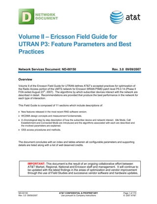
  • 22. Volume II – Ericsson Field Guide for UTRAN P3 ND-00150 AT&T CONFIDENTIAL & PROPRIETARY Page 22 of 170 Rev. 3.0 09/09/2007 Use pursuant to Company instructions © 2007 AT&T 5. Parameters Described Within Context 5.1 Idle Mode Idle Mode is a state every UE enters when it is powered on. It is also the state in which each powered on UE spends most of its time. In this state, the UE must be ready and able to Originate and Terminate calls. This section includes cell selection, but does not include Cell Reselection as Cell Reselection is a function of mobility and as such is covered in the Mobility Management section. 5.1.1 Cell Search Procedure After either power up or entry into network coverage, the UE must begin to read information on the BCCH. The Broadcast Control CHannel (BCCH) is used to broadcast System Information to all UEs within its coverage area. This is accomplished in 3 steps. However, before the 3 steps are described, it is important to understand the Slot and Frame structure of the downlink. A Slot is made up of 2560 Chips (meaning it’s a spread signal). 15 Slots make up one 10 ms Frame. 73 Frames make up one Superframe. 1. Slot Synchronization with the downlink is acquired by correlating the Primary Synchronization Code, common to every cell and known by all UEs, with the Primary Synchronization Channel (P-SCH) transmitted on the downlink. It is important to know that neither the Primary nor the Secondary Synchronization Channel are ever Scrambled using the Primary Scrambling Code. Each cell serving in the UE’s geographic area transmits a Primary Synchronization Channel (P-SCH). The cell that the UE is able to obtain the strongest correlation with is chosen as the serving cell. The Primary Synchronization Channel (P-SCH) power level is controlled by the primarySchPower [Cell, -18, 0.1dB, Fixed] parameter which is set relative to the power of the Primary Common Pilot Channel (CPICH). Figure 1: Slot and Frame Structure S0 S1 S14 ... S2 S13 ... .667 ms F0 F1 ... ... F70 F71 Superframe = 72 frames F2 Frame = 15 Slots Slot = 2560 Chips 10 ms 720 ms The process in which UARFCNs are chosen for a Slot Synchronization attempt is UE implementation dependant.
  • 23. Volume II – Ericsson Field Guide for UTRAN P3 ND-00150 AT&T CONFIDENTIAL & PROPRIETARY Page 23 of 170 Rev. 3.0 09/09/2007 Use pursuant to Company instructions © 2007 AT&T 2. Even though the UE has acquired Slot Synchronization, it still needs to know the Slot number within a Frame (Frames have 15 Slots) so it can know where the Frame begins. It does this by correlating one of the 16 Secondary Synchronization Codes with the Secondary Synchronization Channel (S- SCH). It is important to know that neither the Primary nor the Secondary Synchronization Channel are ever Scrambled using the Primary Scrambling Code. The 16 Secondary Synchronization Codes are used to form 64 unique Secondary Synchronization Channel sequences. Once the UE has decoded 15 successive Secondary Synchronization Codes, it not only knows where the Frame begins, but the Code Group (used in step 3) as well. The UE is now Frame Synchronized. The Secondary Synchronization Channel (S-SCH) power is controlled by the secondarySchPower [Cell, -35, 0.1dB, Fixed] parameter which is set relative to the power of the Primary Common Pilot Channel (CPICH). 3. Now that the UE is Slot and Frame Synchronized, it must still determine the cell’s Primary Scrambling Code before it can begin to read the Broadcast Control CHannel (BCCH). In step 2, the UE discovers the cell’s Code Group. Each Code Group identifies 8 possible Primary Scrambling Codes. The correct Primary Scrambling Code is determined by correlating each of the 8 possibilities with the Common Pilot Channel (CPICH). Once the correct Primary Scrambling Code has been found, the UE can detect the Primary Common Control Physical Channel (P-CCPCH) which carries the Broadcast CHannel (BCH) Transport Channel. The Broadcast CHannel (BCH) transmission power is controlled throughput bchPower [Cell, -31, 0.1dB, Fixed] which is set relative to the power of the Primary Common Pilot Channel (CPICH). The Broadcast CHannel (BCH) carries the Broadcast Control CHannel (BCCH) Logical Channel. The cell’s Primary Scrambling Code is configured using the primaryScramblingCode [Cell, 0 to 511, Integer, Variable] parameter. The Primary Common Control Physical Channel (P-CPPCH) carries the System Frame Number (SFN) which is used as the timing reference for all Physical Channels. The System Frame Number (SFN) ranges from 0 to 4095 (inclusive). For more information about Slot and Frame synchronization, see [3e]. 5.1.2 PLMN Selection Now the UE is able to read the Broadcast Control CHannel (BCCH). If the UE finds its subscribed Public Land Mobile Network (PLMN) it then continues to read System Information from the BCCH. 5.1.2.1 Information on the Broadcast Control CHannel (BCCH) The Broadcast Control Channel (BCCH) broadcasts information consisting of a Master Information Block (MIB), up to 18 System Information Blocks (SIB) types numbered 1-18, and up to 2 Scheduling Blocks (SB). Ericsson has implemented a Master Information Block (MIB) and System Information Blocks (SIB) types 1, 3, 5, 7, 11 and 12. The following breakdown of the Master Information Block (MIB) and System Information Blocks (SIBs) provides an indication of where the UE gets the information necessary in order to maintain Idle Mode, Establish Calls, and Manage Mobility. The “Layer 3 Message” column was derived from TEMS 6.0 log files. The Purpose column provides a brief description of where the parameter applies. • Master Information Block (MIB). The Master Information Block (MIB) is sent at a fixed rate of every 8 Frames (80ms). It contains information that identifies the network as well as the start position and interval of each of the System Information Blocks (SIBs). The Master Information Block (MIB) also contains a Value Tag associated with each System Information Block supported. If the Value Tag for any supported System Information Block changes, the UE must read that System Information Block (SIB). In order to avoid the UE having to read each and every Master Information Block (MIB), a Paging Type 1 message is sent and repeated noOfMibValueTagRetrans [RNC, 0, Retransmissions, Fixed] times to all UEs indicating a Value Tag has changed in the Master Information Block
  • 24. Volume II – Ericsson Field Guide for UTRAN P3 ND-00150 AT&T CONFIDENTIAL & PROPRIETARY Page 24 of 170 Rev. 3.0 09/09/2007 Use pursuant to Company instructions © 2007 AT&T (MIB). Table 7: Master Information Block (MIB) Contents Ericsson Parameter Layer 3 Message Purpose mcc MCC : The Mobile Country Code mnc MNC : The Mobile Network Code sib1StartPos Repx : y Sets the start position of SIB 1 where x equals the repetition period and y equals the SFN / 2. sib1RepPeriod sib-Pos : repx Sets the SIB 1 repetition period where x equals a number of Frames. sib3StartPos Repx : y Sets the start position of SIB 3 where x equals the repetition period and y equals the SFN / 2. sib3RepPeriod sib-Pos : repx Sets the SIB 3 repetition period where x equals a number of Frames. sib5StartPos Repx : y Sets the start position of SIB 5 where x equals the repetition period and y equals the SFN / 2. sib5RepPeriod sib-Pos : repx Sets the SIB 5 repetition period where x equals a number of Frames. sib7StartPos Repx : y Sets the start position of SIB 7 where x equals the repetition period and y equals the SFN / 2. sib7RepPeriod sib-Pos : repx Sets the SIB 7 repetition period where x equals a number of Frames. sib11StartPos Repx : y Sets the start position of SIB 11 where x equals the repetition period and y equals the SFN / 2. sib11RepPeriod sib-Pos : repx Sets the SIB 11 repetition period where x equals a number of Frames. sib12StartPos Repx : y Sets the start position of SIB 12 where x equals the repetition period and y equals the SFN / 2. sib12RepPeriod sib-Pos : repx Sets the SIB 12 repetition period where x equals a number of Frames. • System Information Block 1 (SIB 1). System Information Block 1 (SIB 1) contains Location Area (LA), Routing Area (RA) information and timer parameters. Since this System Information Block contains the Location Area (LA) and Routing Area (RA) information, it must also be read when a LA or RA border is crossed. The parameter sib1PLMNScopeValueTag [Cell, 0 to 31, Integer, Variable] controls when System Information Block 1 (SIB 1) is read and must be set so that neighboring Location Areas and Routing Areas have different values. Table 8: System Information Block 1 (SIB 1) Contents Ericsson Parameter Layer 3 Message Purpose lAC LAC : xxxxx Location Area Code used by CS Core Network t3212 CS domain – T3212 : x Periodic Location Area Update interval in deci-minutes, e.g. 1 = 6 minutes. att CS domain – ATT : x Indicates if the UE is allowed to IMSI Attach to the CS
  • 25. Volume II – Ericsson Field Guide for UTRAN P3 ND-00150 AT&T CONFIDENTIAL & PROPRIETARY Page 25 of 170 Rev. 3.0 09/09/2007 Use pursuant to Company instructions © 2007 AT&T Ericsson Parameter Layer 3 Message Purpose Core Network cnDrxCycleLengthCs CS domain – DRX- CycleLengthCoeff : k Discontinuous Reception (DRX) Cycle Length Coefficient. rAC RAC : xx Routing Area Code used by PS Core Network nmo NMO : x Network Mode of Operation cnDrxCycleLengthPs PS domain – DRX- CycleLengthCoeff : k Discontinuous Reception (DRX) Cycle Length Coefficient. • System Information Block 3 (SIB 3). System Information Block 3 (SIB 3) contains parameters for cell selection and reselection. Table 9: System Information Block 3 (SIB 3) Ericsson Parameter Layer 3 Message Purpose qualMeasQuantity cellSelectQualityMeasur e : x Determines if cell ranking uses quality measurements. sRatSearch s-SearchRAT : x Used to determine when Inter-RAT measurements begin. sHcsRat s-HCS-RAT : x Used to determine when Inter-RAT measurements begin. qQualMin q-QualMin : x Used in Cell Selection and Re-selection qRxLevMin q-RxlevMin : x Used in Cell Selection and Re-selection qHyst2 q-Hyst-I-S : x Used in Cell Selection and Re-selection treSelection t-Reselection-S : x Used in Cell Selection and Re-selection maxTxPowerUl maxAllowedUL-TX- Power : x Max UE power allowed on the uplink. cellReserved CellReservedForOperat orUse : x Indicates if the cell is reserved by the operator. • System Information Block 5 (SIB 5). System Information Block 5 (SIB 5) contains parameters that determine the configuration of Common Physical Channels (PhyCHs) in the cell. Table 10: System Information Block 5 (SIB 5) Ericsson Parameter Layer 3 Message Purpose pichPower pich-PowerOffset : x Power level of the Page Indication CHannel (PICH) relative to the Primary Common Pilot Channel (CPICH) power aichPower Aich-PowerOffset : x Power level of the Acquisition Indication CHannel (AICH) relative to the Primary Common Pilot Channel (CPICH) power primaryCpichPower primaryCPICH-TX- Power : x Power level of the Primary CPICH ConstantValueCprach constantValue : x Used by the UE to calculate initial power on the
  • 26. Volume II – Ericsson Field Guide for UTRAN P3 ND-00150 AT&T CONFIDENTIAL & PROPRIETARY Page 26 of 170 Rev. 3.0 09/09/2007 Use pursuant to Company instructions © 2007 AT&T Ericsson Parameter Layer 3 Message Purpose PRACH. powerOffsetP0 powerRampStep : x Preamble power step when no Acquisition Indicator is received. preambleRetransMax preambleRetransMax : x Maximum number of Preambles sent in one ramping cycle • System Information Block 7 (SIB 7). System Information Block 7 (SIB 7) contains uplink interference value. Due to the fact that this value changes very often, this System Information Block’s interval is controlled by a timer. When the UE receives System Information Block 7 (SIB 7), a timer is started. Once the timer expires, the information is considered invalid and the UE reads the information again. The expiration time is the value of the sib7RepPeriod [RNC, 16, Frames, Fixed] parameter multiplied by the sib7expirationTimeFactor [RNC, 1, Factor, Fixed] parameter. Table 11: System Information Block 7 (SIB 7) Ericsson Parameter Layer 3 Message Purpose n/a ul-Interference Provides uplink Received Total Wideband Power (RTWP). RTWP = No • System Information Block 11 (SIB 11). System Information Block 11 (SIB 11) contains the cell’s soft/softer handover neighbor list including the Primary Scrambling Code of each neighbor. This handover list is supplied to the UE before a call is established so that the UE may make Intra-frequency measurements before receiving the MEASUREMENT CONTROL message from the Serving Radio Network Controller (SRNC). Table 12: System Information Block 11 (SIB 11) Ericsson Parameter Layer 3 Message Purpose reportingRange1a e1a – reportingRange : x CPICH reporting range add threshold. hysteresis1a e1a – hysteresis : x Hysteresis used for CPICH add threshold. timeToTrigger1a e1a – timeToTrigger : x Time between CPICH add and reporting. reportingRange1b e1b – reportingRange : x CPICH reporting range drop threshold. hysteresis1b e1b – hysteresis : x Hysteresis used for CPICH drop threshold. timeToTrigger1b e1b – timeToTrigger : x Time between CPICH drop and reporting. hysteresis1c e1c – hysteresis : 2 Hysteresis used for CPICH replacement. timeToTrigger1c e1c – timeToTrigger : x Time between CPICH replacement and reporting. hysteresis1d e1d – hysteresis : x Hysteresis used in best CPICH replacement. timeToTrigger1d e1d – timeToTrigger : x Time between best CPICH replacement and reporting. • System Information Block 12 (SIB 12). System Information Block 12 (SIB 12) contains measurement control information to be used in the cell.
  • 27. Volume II – Ericsson Field Guide for UTRAN P3 ND-00150 AT&T CONFIDENTIAL & PROPRIETARY Page 27 of 170 Rev. 3.0 09/09/2007 Use pursuant to Company instructions © 2007 AT&T Table 13: System Information Block 12 (SIB 12) Ericsson Parameter Layer 3 Message Purpose n/a n/a There are no configurable parameters reported in this SIB The UE reads System Information only when one of the following events occurs: • The UE is powered up. • Immediately after Cell Reselection (except SIB 1 where the parameter sib1PLMNScopeValueTag [Cell, 0 to 31, Integer, Variable] is used). • The UE receives a Paging Type 1 message indicating System Information has changed. Then the MIB is read which indicates the SIBs that have been updated. • The timer expires for SIBs with an expiration timer (SIB 7 only). Otherwise, in order to conserve battery life, the UE does not read the System Information. This is something to consider when observing Layer 3 messages using a diagnostic UE. 5.1.2.2 Camping on a Suitable Cell Now that the UE has read the Broadcast Control CHannel (BCCH), it knows the values of the parameters that help the UE determine if the cell is suitable. The Cell must not be Reserved and it must be suitable in terms of signal level (Srxlev) and quality (Squal). cellReserved [Cell, NOT_RESERVED, String, Variable] is a cell based parameter sent in System Information Block 3 (SIB3). It has two possible settings; RESERVED and NOT_RESERVED. When set to RESERVED, only UEs with SIMs having an ACC of 11 or 15 (set in the SIM’s HLR profile) will be allowed to camp on the cell assuming the cell is on their home PLMN. See TS 25.306 for details. All other UEs (with SIMs having other than ACC 11 or 15) will avoid camping on the cell. The UE’s Cell Reselection process will also avoid reserved cells. accessClassNbarred [Cell, 0, Integer, Fixed] is another cell based parameter sent in System Information Block 3 (SIB3). It makes it possible to disallow UEs with SIM that have specific Access Classes provisioned for them in the HLR from accessing the network. This parameter differs from the cellReserved [Cell, NOT_RESERVED, String, Variable] parameter in that accessClassNbarred [Cell, 0, Integer, Fixed] still allows the UE to camp on the network. This could cause a worst case senerio wherein the UE camps on the 3G network, but is not allowed to register. The signal level (Srxlev) and quality (Squal) parameters are commonly referred to as the “S” parameters. Srxlev = Qrxlevmeas – qRxLevMin [Cell, -115, dBm, Fixed] – Pcompensation Where: • Srxlev is the signal level criteria used to determine a cell’s suitability. • Qrxlevmeas is the Primary Common Pilot Channel Received Signal Code Power (PCPICH RSCP) as measured by the UE. • qRxLevMin [Cell, -115, dBm, Fixed] is sent in System Information Block 3 (SIB 3) for the serving cell which
  • 28. Volume II – Ericsson Field Guide for UTRAN P3 ND-00150 AT&T CONFIDENTIAL & PROPRIETARY Page 28 of 170 Rev. 3.0 09/09/2007 Use pursuant to Company instructions © 2007 AT&T indicates the minimum acceptable Primary Common Pilot Channel Received Signal Code Power (PCPICH RSCP). • The quantity called Pcompensation is the maximum value of maxTxPowerUl [Cell, 24, dBm, Fixed] – P or 0 where maxTxPowerUl [Cell, 24, dBm, Fixed] is sent in System Information Block 3 (SIB 3) which indicates the maximum transmission power allowed for a UE and P is the output power of the UE according to its Power Class. Example part 1 of 3. A Power Class 3 UE is served at a path loss 10 dB less than the maximum path loss as indicated in the Link Budget table, qRxLevMin [Cell, -115, dBm, Fixed] is set conservatively at -115 dBm, and maxTxPowerUl [Cell, 24, dBm, Fixed] is set at 24 dBm. Pcompensation is the maximum value of either 24 dBm – 24 dBm or 0. So Srxlev = -105 dBm minus -115 dBm minus 0. Srxlev = 10. Squal = Qqualmeas – qQualMin [Cell, -19, dB, Fixed] Where: • Qqualmeas is the Primary Common Pilot Channel Chip Energy over Noise Spectral Density (PCPICH Ec/No) as measured by the UE. • qQualMin [Cell, -19, dB, Fixed] is sent in System Information Block 3 (SIB 3) for the serving cell indicates the minimum acceptable Primary Common Pilot Channel Chip Energy over Noise Spectral Density (PCPICH Ec/No) for the cell. Example part 2 of 3. The UE is served at an Ec/No of -14 dB and qQualMin [Cell, -19, dB, Fixed] is set at -19 dB. -14 dB minus -19 dB. Squal = 5 dB. The cell is considered suitable if its cell selection criterion (S criterion) is met. In order for the S criterion to be met, Srxlev and Squal must have positive values. Example part 3 of 3. The UE calculates both S criteria with positive resulting values. The cell is considered acceptable where the S criterion is concerned. It is now allowed to transmit on the uplink. 5.1.3 IMSI and GPRS Attach Assuming now that the UE has found its home PLMN and is Camping on a suitable cell, it must International Mobile Subscriber Identity (IMSI) Attach and General Packet Radio Service (GPRS) Attach to the Circuit Switched (CS) and Packet Switched (PS) Core Networks (CN) respectively. This process is also known as Registration. 5.1.3.1 Attach Procedure If att [LA, 1=TRUE, Integer, Fixed] sent in System Information Block 1 (SIB 1) is set to 1, the UE must establish a Signaling Connection to notify the Circuit Switched Core Network (CS-CN) and Packet Switched Core Network (PS-CN) that it is powered on and within network coverage. Signaling Connections are always initiated by the UE. First, the UE must access the Node B in order to send a request to the RNC to establish a Radio Resource Control (RRC) Connection. This is done through the Physical Random Access Channel (PRACH) on the uplink and the Acquisition Indicator Channel (AICH) on the downlink. The UE sends successive attempts on the uplink, each at a greater power level until the Node B responds on the Acquisition Indicator CHannel (AICH) on the downlink. The Acquisition Indicator CHannel (AICH) power is set relative to the Primary Common Pilot CHannel (PCPICH) through
  • 29. Volume II – Ericsson Field Guide for UTRAN P3 ND-00150 AT&T CONFIDENTIAL & PROPRIETARY Page 29 of 170 Rev. 3.0 09/09/2007 Use pursuant to Company instructions © 2007 AT&T aichPower [Cell, -6, dB, Fixed]. The process of sending successive attempts, each at an increased power level, is known as Preamble Ramping. The initial power on the PRACH is determined by the UE using the following formula: P_PRACH = L_PCPICH + RTWP + ConstantValueCprach [Cell, -27, dB, Fixed] • P_PRACH is the power used for the initial PRACH attempt. • L_PCPICH is the path loss estimated by the UE (difference between primaryCpichPower [Cell, 300, 0.1dBm, Fixed] as indicated in SIB 5 and PCPICH RSCP as measured by the UE). • RTWP is the Received Total Wideband Power measured by the Node B as indicated in SIB 7. • ConstantValueCprach [Cell, -27, dB, Fixed] determines the level below the Received Total Wideband Power at which Preamble Ramping begins. For example, a UE is served at a path loss 10 dB less than the maximum path loss as indicated in the Link Budget table, so L_PCPICH = 132 dB. Let’s also say the RTWP = -105 dBm and ConstantValueCprach [Cell, -27, dB, Fixed] = -27 dB. The sum of these values, or P_PRACH, is 0 dBm. The UE will begin the attempt at 0 dBm. Subsequent transmission attempts within a Ramping Cycle are made at an increased power level relative to the former attempt. The increase in power level between steps is controlled by the parameter powerOffsetP0 [Cell, 2, dB, Fixed] which the UE reads from System Information Block (SIB) 5. The UE ceases its access attempt as soon as it receives an Acknowledgement Indicator (AI) on the downlink Acquisition Indication CHannel (AICH). However, the UE is not allowed to ramp its power indefinitely. The preambleRetransMax [Cell, 15, Preambles, Fixed] parameter in SIB 5 controls how many successive Preambles the UE can transmit within one Ramping Cycle and the maxPreambleCycle [Cell, 3, Cycles, Fixed] parameter controls how many Ramping Cycles can be attempted before the UE aborts the access attempt. Figure 2: Power Ramping on RACH powerOffsetP0 AICH RACH Power (dB) Time P_PRACH preambleRetransMax (RampingCycle) AI MessagePart powerOffsetPpm As soon as the UTRAN responds with an Acknowledgement Indicator (AI) on the downlink, the UE sends the PRACH Message Part informing the Radio Network Controller (RNC) that it wishes to set up a Radio
  • 30. Volume II – Ericsson Field Guide for UTRAN P3 ND-00150 AT&T CONFIDENTIAL & PROPRIETARY Page 30 of 170 Rev. 3.0 09/09/2007 Use pursuant to Company instructions © 2007 AT&T Resource Control (RRC) Connection. The power at which PRACH Message Part is sent is equal to the sum of the power of the successful transmission attempt and powerOffsetPpm [Cell, 0, dB, Fixed]. Once the UE and Radio Network Controller (RNC) have established a Radio Resource Control (RRC) Connection, the RNC establishes an Iu Control Plane connection over the Iu interface to the appropriate Core Network (CN) element(s), i.e. the SGSN, MSC or both. The resulting Transparent Message Transfer connection between the UE and Core Network (CN) element(s) allows the exchange of Non- Access Stratum (NAS) messages such as Registrations, Location or Routing Area Updates, and Service Requests for User Plane connections. The figure below details all of the steps necessary to complete a Radio Resource Control (RRC) Connection. Following the figure are detailed explanations for each step. Figure 3: RRC Connection Signaling Flow 13 L1 Synchronization 1 11 Transport Bearer Synchronization 7 AAL2 Connection Setup for DCH Iub Uu UE RNC Node B Activated Algorithms: - Power Control - Iub and Uu Timing Scheduling - Admission Control 3 Radio Link Setup Request NBAP NBAP 4 Start Receive of UL DPCH Start Radio Link Supervision 8 Suspend SRB3, SRB4 and other RLC AM entities 9 Start Transmission of DL DPCH 12 Radio Link Restore Indication NBAP NBAP 14 RRC Connection Request RRC RRC RACH Message Part Radio Link Setup Response NBAP NBAP 6 Resource Allocation 5 2 Initiate UE Context RRC Connection Setup RRC RRC 10 FACH RRC Connection Complete RRC RRC 15 DCH 16 Resume SRB3, SRB4 and other RLC AM entities 1. RRC Connection Request. After the UE receives the Acknowledgement Indicator (AI) on the downlink, it initiates the establishment of a Radio Resource Control (RRC) connection by sending the Radio Resource Control (RRC) Connection Request message with an establishment cause of
  • 31. Volume II – Ericsson Field Guide for UTRAN P3 ND-00150 AT&T CONFIDENTIAL & PROPRIETARY Page 31 of 170 Rev. 3.0 09/09/2007 Use pursuant to Company instructions © 2007 AT&T “Registration” within the Message Part using the Random Access Channel (RACH) Transport Channel. 2. Initiate UE Context. The Radio Resource Control (RRC) Connection attempt is assigned a UTRAN Radio Network Temporary Identity (U-RNTI) which is unique within the network. 3. Activated Algorithms. At this point, the Power Control algorithm sets the initial downlink and uplink Dedicated Physical Data CHannel (DPDCH) and Dedicated Physical Control CHannel (DPCCH) transmission power. These channels are time multiplexed on the downlink and code (I/Q) multiplexed on the uplink. Together they are typically referred to as a Dedicated Physical CHannel (DPCH). The following initial power level parameters are used whenever a Radio Link is set up. The initial downlink Dedicated Physical Data CHannel (DPDCH) power is determined using the following formula: P_DL_DPDCH = primaryCpichPower [Cell, 300, 0.1dBm, Fixed] + (dlInitSirTarget [RNC, 41, 0.1dB, Fixed] - Ec/No_PCPICH) + cBackOff [RNC, 0, 0.25dB, Fixed] + 10 log(2/SF_DL_DPDCH) Where: • P_DL_DPDCH is the initial downlink Dedicated Physical Data CHannel (DPDCH) power. • primaryCpichPower [Cell, 300, 0.1dBm, Fixed] sets the power of the Primary Common Pilot Channel (P-CPICH) sent in SIB 5. • dlInitSirTarget [RNC, 41, 0.1dB, Fixed] sets the required initial Signal to Interference Ratio (SIR) Target. • Ec/No_PCPICH is the ratio of Chip Energy to the Noise Power Spectral Density of the Primary Common Pilot CHannel (P-CPICH) as measured by the UE. If this measurement is not available, ecNoPcpichDefault [RNC, - 16, dB, Fixed] is used. • cBackOff [RNC, 0, 0.25dB, Fixed] is used to offset the value of P_DL_DPDCH. • SF_DL_DPDCH is the Spreading Factor of the downlink Dedicated Physical Data CHannel (DPDCH). The initial downlink Dedicated Physical Control CHannel (DPCCH) power is set relative to the initial downlink Dedicated Physical Data Channel (DPDCH) power by means of a series of offsets: P_DL_DPCCH_TFCI = (P_DL_DPDCH + pO1 [RNC, 0, 0.25dB, Fixed] ) P_DL_DPCCH_TPC = (P_DL_DPDCH + pO2 [RNC, 12, 0.25dB, Fixed] ) P_DL_DPCCH_PILOT = (P_DL_DPDCH + pO3 [RNC, 12, 0.25dB, Fixed] )
  • 32. Volume II – Ericsson Field Guide for UTRAN P3 ND-00150 AT&T CONFIDENTIAL & PROPRIETARY Page 32 of 170 Rev. 3.0 09/09/2007 Use pursuant to Company instructions © 2007 AT&T Figure 4: Downlink DPCCH Power pO2 TPC DPDCH Time Data 1 DPCCH DPDCH DPCCH Data 2 TFCI Pilot DL Power (dB) pO3 pO1 1 Timeslot (10ms) Where: • P_DL_DPCCH_TFCI is the initial power of the Dedicated Physical Control CHannel Transport Format Combination Indicator (DPCCH TFCI) field. • pO1 [RNC, 0, 0.25dB, Fixed] sets the offset between the Data field and the Dedicated Physical Control CHannel Transport Format Combination Indicator (DPCCH TFCI) field. • P_DL_DPCCH_TPC is the initial power of the Dedicated Physical Control CHannel Transmit Power Control (DPCCH TPC) field. • pO2 [RNC, 12, 0.25dB, Fixed] sets the offset between the Data field and the Dedicated Physical Control CHannel Transmit Power Control (DPCCH TPC) field. • P_DL_DPCCH_PILOT is the initial power of the Dedicated Physical Control CHannel Pilot field. • pO3 [RNC, 12, 0.25dB, Fixed] sets the offset between the Data field and the Dedicated Physical Control CHannel Pilot field. The initial uplink Dedicated Physical Control CHannel (DPCCH) power is determined using the following formula: Power_UL_DPCCH_INIT = DPCCH_POWER_OFFSET - RSCP_PCPICH Where: • Power_UL_DPCCH_INIT is the initial uplink Dedicated Physical Control CHannel (DPCCH) power. • DPCCH_POWER_OFFSET is calculated in the Radio Network Controller (RNC) and sent to the UE according to the following formula: DPCCH_POWER_OFFSET = primaryCpichPower [Cell, 300, 0.1dBm, Fixed] + RTWP + ulInitSirTarget - 10 log (SF_DPCCH) + cPO [RNC, 0, 0.1dB, Fixed] Where: • DPCCH_POWER_OFFSET is an offset applied to Power_UL_DPCCH_INIT.
  • 33. Volume II – Ericsson Field Guide for UTRAN P3 ND-00150 AT&T CONFIDENTIAL & PROPRIETARY Page 33 of 170 Rev. 3.0 09/09/2007 Use pursuant to Company instructions © 2007 AT&T • primaryCpichPower [Cell, 300, 0.1dBm, Fixed] sets the power of the Primary Common Pilot CHannel (P- CPICH). If the Radio Network Controller (RNC) does now know the Primary Common Pilot CHannel (P-CPICH) power, as is the case when the UE is served by a Drift Radio Network Controller (DRNC), pcpichPowerDefault [RNC, 33, dBm, Fixed] is used instead. • RTWP is the Received Total Wideband Power level on the uplink measured by the Node B. • ulInitSirTarget is one of the following configurable parameters based upon the Spreading Factor of the Radio Bearer. • ulInitSirTargetSrb [RNC, 57, 0.1dB, Fixed] for stand-alone Signaling Radio Bearers (SRB). • ulInitSirTargetLow [RNC, 49, 0.1dB, Fixed] for Radio Access Bearers (RABs) having minimum Dedicated Physical Data CHannel Spreading Factors (DPDCH SF) equal to or higher than 32. • ulInitSirTargetHigh [RNC, 82, 0.1dB, Fixed] for RABs having minimum Dedicated Physical Data CHannel Spreading Factors (DPDCH SF) equal to 16 or 8. • ulInitSirTargetExtraHigh [RNC, 92, 0.1dB, Fixed] for Radio Access Bearers (RABs) having minimum Dedicated Physical Data CHannel Spreading Factors (DPDCH SF) equal to or lower than 4. • SF_DPCCH is the Spreading Factor (SF) for the Dedicated Physical Control CHannel. • cPO [RNC, 0, 0.1dB, Fixed] is used to offset the initial uplink Dedicated Physical Data CHannel (DPDCH) power. • RSCP_PCPICH is the Received Signal Code Power (RSCP) of the Primary Common Pilot Channel (P-CPICH). The initial uplink Dedicated Physical Data CHannel (DPDCH) power is determined according to the relative power offset between the Dedicated Physical Control CHannel (DPCCH) and Dedicated Physical Data Channel (DPDCH) as described in 3GPP TS 25.214. The UTRAN determines and signals the gain factor to the UE for the reference Transport Format Combination (TFC) only. The UE then computes the gain factors for other Transport Format Combinations (TFCs) based on the value for the reference Transport Format Combination (TFC). In addition to uplink and downlink power control, the Iub and Uu Timing Scheduling algorithms calculate channel timing parameters. The Admission Control algorithm checks if the new radio link can be allowed in the cell. The Code Control algorithms allocate the uplink scrambling code, downlink scrambling code, and downlink channelization code. 4. Radio Link Setup Request. The RNC orders the Node B to reserve the necessary resources for a new Node B communication context. 5. Resource Allocation. The Node B reserves the necessary resources for a new communication context and calculates link characteristic parameters from the received uplink and downlink Transport Format Combination Indicator (TFCI) or Transport Format Set (TFS) information. 6. Radio Link Setup Response. The Node B indicates to the RNC that the necessary resources are allocated for the radio link. It includes the binding identifier and transport layer address for the AAL2 connection. 7. AAL2 Connection Setup for DCH. The transport bearer (AAL2 connection) needed for signaling is set up over the Iub by the RNC. 8. Start Receive of UL DPCH – Start Radio Synchronization. The Radio Link Set Supervision algorithm in the Node B starts evaluating the synchronization status of the Radio Link Set (RLS). 9. Suspend SRB3, SRB4, and other RLC AM entities. Signaling Radio Bearer 3 (SRB 3), Signaling Radio Bearer 4 (SRB 4), and other Radio Link Control Acknowledged Mode (RLC AM) entities are suspended.
  • 34. Volume II – Ericsson Field Guide for UTRAN P3 ND-00150 AT&T CONFIDENTIAL & PROPRIETARY Page 34 of 170 Rev. 3.0 09/09/2007 Use pursuant to Company instructions © 2007 AT&T 10. RRC Connection Setup. The RNC indicates the UE state shall be CELL_DCH. The message is sent in Unacknowledged mode on the Forward Access CHannel (FACH). 11. Transport Bearer Synchronization. Transport Bearer Synchronization is achieved in the downlink between RNC and Node B for each Dedicated CHannel (DCH). 12. Start Transmission of DL DPCH. The Node B only starts transmitting on the new radio link when the downlink user plane (Dedicated Physical Data CHannel – DPDCH) is considered synchronized. 13. L1 Synchronization. Layer 1 synchronization is achieved between UE and Node B. 14. Radio Link Restore Indication. The Node B notifies the RNC that it has achieved uplink Layer 1 synchronization with the UE. 15. RRC Connection Complete. The UE starts the uplink transmission only after the reception of downlink Dedicated Physical Channel (DPCH). The UE capabilities requested in step 10 are included in this message. This information is used by the Radio Access Bearer (RAB) establishment procedure, UE Security Handling, and the Channel Switching function. Radio Resource Control (RRC) messages can now be sent in acknowledged mode on a Dedicated CHannel (DCH). 16. Resume SRB3, SRB4, and other RLC AM entities. The SRB3, SRB4, and other Radio Link Control Acknowledged Mode (RLC AM) entities are resumed. Through this dedicated connection, the UE is able to Register with the appropriate Core Network (CN) Element(s). 5.1.4 Location and Routing Area Updates Location and Routing Area Updates, also known as Registration updates, must be performed in order to provide the SGSN and MSC with an awareness of where the UE is located. Given the UE’s location, the Core Network (CN) element can page the UE to deliver calls. This awareness helps to avoid unnecessary paging when the UE is either turned off or is outside of the coverage area. Location Areas are defined through the lAC [LA, N/A, Integer, Variable] broadcast on the Broadcast Control CHannel (BCCH) in System Information Block 1 (SIB 1). Routing Areas are defined through the rAC [RNC, N/A, Integer, Variable] also broadcast on the Broadcast Control CHannel (BCCH) in System Information Block 1 (SIB 1). Besides IMSI and GPRS Attaches, there are basically two different types of Registration update; Normal and Periodic. 5.1.4.1 Normal Update A Normal Location or Routing Area update is performed when the UE either leaves Connected Mode, or performs a Cell Reselection in Idle Mode to a cell within a different Location or Routing Area. 5.1.4.2 Periodic Update In addition to Normal Updates, Periodic Updates are performed. These updates are preformed regardless of whether the UE is in Idle Mode or Connected Mode (CELL_DCH). • Circuit Switched Core Network. The interval at which the UE periodically updates the Circuit Switched Core Network (CS-CN) is set using the configurable t3212 [LA, 10, 6minutes, Fixed] parameter sent on the Broadcast Control CHannel (BCCH) in System Information Block 1 (SIB 1). • Packet Switched Core Network. The interval at which the UE periodically updates the Packet Switched Core
  • 35. Volume II – Ericsson Field Guide for UTRAN P3 ND-00150 AT&T CONFIDENTIAL & PROPRIETARY Page 35 of 170 Rev. 3.0 09/09/2007 Use pursuant to Company instructions © 2007 AT&T Network (PS-CN) is set using the t3312 timer. This timer is set in the SGSN and sent to the UE via both the Attach and the Routing Area Update messages. The following table provides parameter ranges and default values involved in getting the UE into Idle Mode. They are listed in the same order they were presented. The Level column indicates the network element that owns the parameter. The class column indicates if the parameter is set based on Policy (must be set this way), Fixed (recommended to be set this way) and Variable (set at your discretion). 5.2 Call Establishment Given the UE has successfully entered Idle Mode; it must then be able to originate and terminate calls within acceptable Accessibility measures. This section considers all of the algorithms invoked during the process of establishing a call. 5.2.1 Radio Access Bearer A Radio Access Bearer (RAB) is a connection between the UE and the Mobile Switching Center (MSC) in the case of a Circuit Switched (CS) connection or between the UE and Serving GPRS Support Node (SGSN) in the case of a Packet Switched connection. There is also the possibility of the UE connecting to both the MSC and the SGSN as is the case in both SP0 and SP64. The Radio Access Bearer is set up according to the Requested Service after the Signaling Connection is established through a Signaling Radio Bearer. In the case of UE initiated connections where a Radio Access Bearer does not already exist, the Requested Service is sent in the Random Access CHannel (RACH) Message Part. Although the Requested Service could be sent by the UE, all Radio Access Bearers are actually initiated by the Core Network (CN). The variables within Quality of Service (QoS) fall into three main categories based upon the user’s need for guaranteed throughput and/or latency. The three categories are Conversational; which provides guaranteed low latency and throughput, Streaming; which provides guaranteed throughput but no guarantee for latency, and Interactive (also referred to as Background) which provides guarantees for neither throughput nor latency. Another variable determines which side of the Core Network is used. In general, all Packet Switched Radio Access Bearers are connected to the SGSN and all Circuit Switched Radio Access Bearers are connected to the MSC. The following types of Radio Access Bearers (RABs) are supported by the Ericsson UTRAN. • Conversational Circuit Switched Speech AMR 12.2kb. This is the typical Speech Radio Access Bearer. Given its Conversational Quality of Service (QoS) class, low latency and constant throughput are guaranteed. The Conversational class of service is Transparent, meaning that in order to keep latency as low as possible, there is no Transport layer Block retransmission service offered. • Conversational Circuit Switched Speech AMR 12.2kb plus Interactive Packet Switched 64/64. This type of Radio Access Bearer supports concurrent Circuit Switched Speech and Packet Switched Data. The Interactive Quality of Service (QoS) class Data connection can support a data rate of 64kb in the Uplink and 64kb in the downlink. Neither latency nor throughput is guaranteed for the Packet Switched connection. Ericsson refers to this type of Radio Access Bearer (RAB) as SP64. • Conversational Circuit Switched Speech AMR 12.2kb plus Interactive Packet Switched 64/HS. This type of Radio Access Bearer supports concurrent Circuit Switched Speech and Packet Switched Data. The Interactive
  • 36. Volume II – Ericsson Field Guide for UTRAN P3 ND-00150 AT&T CONFIDENTIAL & PROPRIETARY Page 36 of 170 Rev. 3.0 09/09/2007 Use pursuant to Company instructions © 2007 AT&T Quality of Service (QoS) class Data connection can support a data rate of 64kb in the Uplink and HSDPA for the downlink. Neither latency nor throughput is guaranteed for the Packet Switched connection. • Conversational Circuit Switched Speech AMR 12.2kb plus Interactive Packet Switched 384/HS. This type of Radio Access Bearer supports concurrent Circuit Switched Speech and Packet Switched Data. The Interactive Quality of Service (QoS) class Data connection can support a data rate of 384kb in the Uplink and HSDPA for the downlink. Neither latency nor throughput is guaranteed for the Packet Switched connection. • Conversational Circuit Switched Speech AMR 12.2kb plus Interactive Packet Switched 0/0. This Radio Access Bearer (RAB) offers both Speech and a 0 bit rate Packet Switched connection. The 0 bit rate Packet Switched connection is used as a “stepping stone” between 64/64 and Idle Mode. The result is a reduction in latency from the end user’s perspective when using interactive applications such as Web Browsing. Ericsson refers to this type of Radio Access Bearer (RAB) as SP0. The availability of this Radio Access Bearer (RAB) is controlled through multiRabSp0Available [RNC, 1=TRUE, Binary, Fixed]. • Conversational Circuit Switched Data 64. This Radio Access Bearer (RAB) provides a Conversational class 64kb/s Unrestricted Digital Information (UDI) connection between the UE and the Circuit Switched Core Network. The Conversational class of service is Transparent, meaning that in order to keep latency as low as possible, there is no Transport layer Block retransmission service offered. • Conversational Circuit Switched Data 64 plus Interactive Packet Switched 8/8. This Radio Access Bearer (RAB) provides a Conversational class 64kb/s Unrestricted Digital Information (UDI) connection between the UE and the Circuit Switched Core Network plus an Interactive class 8kb uplink, 8kb downlink Packet Switched connection between the UE and Packet Switched Core Network. Ericsson refers to this type of Radio Access Bearer (RAB) as UDI8. The availability of this Radio Access Bearer (RAB) is controlled through multiRabUdi8Available [RNC, 0=FALSE, Binary, Fixed]. • Streaming Circuit Switched 57.6. This Radio Access Bearer (RAB) provides a Streaming class connection between the UE and Circuit Switched Core Network with guaranteed throughput of up to 57.6kb and guaranteed low latency. • Streaming Packet Switched 16/64. This Radio Access Bearer (RAB) provides a Streaming class connection between the UE and the Packet Switched Core Network with guaranteed throughput of up to 57.6kb on the downlink and 16kb in the uplink. Latency is not guaranteed. • Streaming Packet Switched 16/64 plus Interactive Packet Switched 8/8. This Radio Access Bearer (RAB) provides a Streaming class connection between the UE and the Packet Switched Core Network with guaranteed throughput of up to 57.6kb on the downlink and 16kb in the uplink plus an interactive class 8kb uplink, 8kb downlink Packet Switched connection between the UE and Packet Switched Core Network. Throughput is only guaranteed for the Streaming class connection. Latency is not guaranteed for either connection. • Streaming Packet Switched 16/128. This Radio Access Bearer (RAB) provides a Streaming class connection between the UE and the Packet Switched Core Network with guaranteed throughput of up to 112kb on the downlink and 16kb in the uplink. Latency is not guaranteed. • Streaming Packet Switched 16/128 plus Interactive Packet Switched 8/8. This Radio Access Bearer (RAB) provides a Streaming class connection between the UE and the Packet Switched Core Network with a guaranteed throughput of up to 112kb on the downlink and 16kb in the uplink plus an interactive class 8kb uplink, 8kb downlink Packet Switched connection between the UE and Packet Switched Core Network. Throughput is only guaranteed for the Streaming class connection. Latency is not guaranteed for either connection. The availability of this Radio Access Bearer (RAB) is controlled through psStreaming128 [RNC, 0=FALSE, Binary, Fixed]. • Interactive Packet Switched HSDPA with 384 uplink. This Radio Access Bearer provides an interactive connection between the UE and Packet Switched Core Network of 1.8Mb on the downlink and 384kb on the uplink. Neither latency nor throughput is guaranteed. The availability of this Radio Access Bearer (RAB) is controlled through allow384HsRab [RNC, 1=TRUE, Binary, Fixed]. • Interactive Packet Switched HSDPA with 64 uplink. This Radio Access Bearer provides an interactive connection between the UE and Packet Switched Core Network of 1.8Mb on the downlink and 64kb on the uplink. Neither latency nor throughput is guaranteed. • Interactive Packet Switched DCH/DCH. This Radio Access Bearer (RAB) provides an interactive connection between the UE and Packet Switched Core Network of 64kb, 128kb or 384kb on the uplink and 64kb, 128kb or 384kb on the downlink. Neither latency nor throughput is guaranteed. The initial Dedicated Channel (DCH)