Downloaded 12 times


![Convention Description
[ ] Syntax components displayed within square brackets are optional.
Default responses to system prompts are enclosed in square brackets.
{ x | y | z } A choice of required parameters is enclosed in curly brackets separated by
vertical bars. You must select one of the options.
In Fibre Channel products, square brackets may be used instead for this
purpose.
x | y A vertical bar separates mutually exclusive elements.
< > Nonprinting characters, for example, passwords, are enclosed in angle
brackets.
... Repeat the previous element, for example, member[member...].
Indicates a “soft” line break in command examples. If a backslash separates
two lines of a command input, enter the entire command at the prompt without
the backslash.
Notes, cautions, and warnings
Notes, cautions, and warning statements may be used in this document. They are listed in the order of
increasing severity of potential hazards.
NOTE
A Note provides a tip, guidance, or advice, emphasizes important information, or provides a reference
to related information.
ATTENTION
An Attention statement indicates a stronger note, for example, to alert you when traffic might be
interrupted or the device might reboot.
CAUTION
A Caution statement alerts you to situations that can be potentially hazardous to you or cause
damage to hardware, firmware, software, or data.
DANGER
A Danger statement indicates conditions or situations that can be potentially lethal or
extremely hazardous to you. Safety labels are also attached directly to products to warn of
these conditions or situations.
Notes, cautions, and warnings
8 Brocade ICX 7250 Switch Hardware Installation Guide
53-1003898-01](https://image.slidesharecdn.com/fastiron-08040-icx7250-installguide-161005220418/85/Fastiron-08040-icx7250-installguide-8-320.jpg)


![Power precautions
CAUTION
Use a separate branch circuit for each power cord, which provides redundancy in case one of
the circuits fails.
CAUTION
Ensure that the device does not overload the power circuits, wiring, and over-current protection.
To determine the possibility of overloading the supply circuits, add the ampere (amp) ratings of
all devices installed on the same circuit as the device. Compare this total with the rating limit for
the circuit. The maximum ampere ratings are usually printed on the devices near the input
power connectors.
DANGER
Disconnect the power cord from all power sources to completely remove power from the device.
CAUTION
Before plugging a cable into to any port, be sure to discharge the voltage stored on the cable by
touching the electrical contacts to ground surface.
DANGER
If the installation requires a different power cord than the one supplied with the device, make
sure you use a power cord displaying the mark of the safety agency that defines the regulations
for power cords in your country. The mark is your assurance that the power cord can be used
safely with the device.
Preparing the installation site
EPS4000 external power supplies can be mounted in a standard 19-inch equipment rack or on a flat
surface.
The installation site should meet these requirements:
• Be at the center of all the devices you want to link, and near a power outlet.
• Maintain temperatures within 0 to 50°C (32 to 122°F) and humidity levels within 5 to 95%, non-
condensing.
• Provide adequate space (approximately 5.08 cm [2 in.]) on all sides for proper airflow.
• Be accessible for installing, cabling, and maintaining the devices.
• Allow the status LEDs to be clearly visible.
• Allow for twisted-pair cables to be routed away from power lines, fluorescent lighting fixtures, and
other sources of electrical interference, such as radios and transmitters.
• Provide a separate grounded power outlet that provides 100 to 240 VAC, 50 - 60 Hz, is within 2.44 m
(8 ft) of each device, and is powered from an independent circuit breaker.
• As with any electrical equipment, a filter or surge suppressor is recommended.
Rack-mount installation considerations
Before mounting the external power supply in a rack, consider the following factors:
Power precautions
Brocade ICX 7250 Switch Hardware Installation Guide 41
53-1003898-01](https://image.slidesharecdn.com/fastiron-08040-icx7250-installguide-161005220418/85/Fastiron-08040-icx7250-installguide-41-320.jpg)
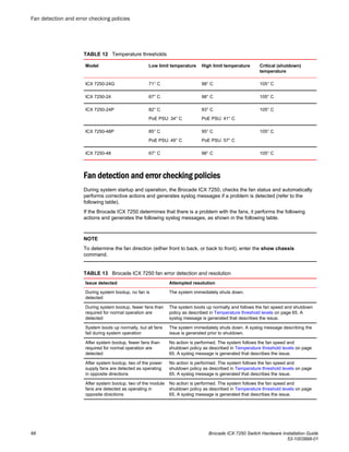

![Displaying CPU usage
You can display the amount of the CPU in use. To do so, enter the show cpu command at any level of
the CLI.
device# show cpu
20 percent busy, from 318 sec ago
1 sec avg: 2 percent busy
5 sec avg: 1 percent busy
60 sec avg: 1 percent busy
300 sec avg: 1 percent busy
Removing MAC address entries
You can remove the following types of learned MAC address entries from the system MAC address
table:
• All MAC address entries
• All MAC address entries for a specified Ethernet port
• All MAC address entries for a specified VLAN
• A specified MAC address entry in all VLANs
For example, to remove entries for the MAC address 00-00-00 in all VLANs, enter the following
command at the privileged EXEC level of the CLI.
device# clear mac-address 00-00-00
Syntax: clear mac-address [ mac-address | ethernet port-num | vlan number ]
If you enter the clear mac-address command without any parameters, the software removes all MAC
entries.
Use the clear mac-address mac-address command to remove a specified MAC address from all
VLANs. Specify the MAC address in the following format: HHHH.HHHH.HHHH.
Use the clear mac-address ethernet port-num command to remove all MAC addresses for a specified
Ethernet port.
Use the clear mac-address vlan number command to remove all MAC addresses for a specified
VLAN.
Displaying CPU usage
Brocade ICX 7250 Switch Hardware Installation Guide 69
53-1003898-01](https://image.slidesharecdn.com/fastiron-08040-icx7250-installguide-161005220418/85/Fastiron-08040-icx7250-installguide-69-320.jpg)


The Brocade ICX 7250 is an Ethernet switch available in models with 24 or 48 fixed ports and 4 or 8 uplink/stacking ports. It supports 10/100/1000BASE-T ports, SFP+ uplink ports, and optional PoE. Management is provided via a console port and out-of-band management port.