This document is the ExtremeWare 7.2.0 Software User Guide. It provides information about using the ExtremeWare software, including features like VLANs, spanning tree protocol, quality of service, routing, and security. It describes how to access the switch through the console, Ethernet management port, Telnet, SSH, and web interface. It also covers basic management tasks like configuring management access, DNS, ping, traceroute, and authentication methods.


![Preface
Terminology
When features, functionality, or operation is specific to a modular or stand-alone switch family, the
family name is used. Explanations about features and operations that are the same across all product
families simply refer to the product as the “switch.”
Conventions
Table 1 and Table 2 list conventions that are used throughout this guide.
Table 1: Notice Icons
Icon Notice Type Alerts you to...
Note Important features or instructions.
Caution Risk of personal injury, system damage, or loss of data.
Warning Risk of severe personal injury.
Table 2: Text Conventions
Convention Description
Screen displays This typeface indicates command syntax, or represents information as it appears on the
screen.
The words “enter” When you see the word “enter” in this guide, you must type something, and then press
and “type” the Return or Enter key. Do not press the Return or Enter key when an instruction
simply says “type.”
[Key] names Key names are written with brackets, such as [Return] or [Esc].
If you must press two or more keys simultaneously, the key names are linked with a
plus sign (+). Example:
Press [Ctrl]+[Alt]+[Del].
Words in italicized type Italics emphasize a point or denote new terms at the place where they are defined in
the text.
Related Publications
The publications related to this one are:
• ExtremeWare release notes
• ExtremeWare 7.2.0 Software Command Reference Guide
• Extreme Networks Consolidated Hardware Guide
Documentation for Extreme Networks products is available on the World Wide Web at the following
location:
28 ExtremeWare 7.2.0 Software User Guide](https://image.slidesharecdn.com/extremewareuserguide72-110124002726-phpapp01/85/Extreme-wareuserguide72-28-320.jpg)


![Accessing the Switch
5 The value part of the command specifies how you want the parameter to be set. Values include
numerics, strings, or addresses, depending on the parameter.
6 After entering the complete command, press [Return].
NOTE
If an asterisk (*) appears in front of the command-line prompt, it indicates that you have outstanding
configuration changes that have not been saved. For more information on saving configuration changes,
see Appendix A.
Syntax Helper
The CLI has a built-in syntax helper. If you are unsure of the complete syntax for a particular command,
enter as much of the command as possible and press [Tab]. The syntax helper provides a list of options
for the remainder of the command, and places the cursor at the end of the command you have entered
so far, ready for the next option.
If the command is one where the next option is a named component, such as a VLAN, access profile, or
route map, the syntax helper will also list any currently configured names that might be used as the
next option. In situations where this list might be very long, the syntax helper will list only one line of
names, followed by an ellipses to indicate that there are more names than can be displayed.
The syntax helper also provides assistance if you have entered an incorrect command.
Abbreviated Syntax
Abbreviated syntax is the shortest unambiguous allowable abbreviation of a command or parameter.
Typically, this is the first three letters of the command. If you do not enter enough letters to allow the
switch to determine which command you mean, the syntax helper will provide a list of the options
based on the portion of the command you have entered.
NOTE
When using abbreviated syntax, you must enter enough characters to make the command unambiguous
and distinguishable to the switch.
Command Shortcuts
All named components of the switch configuration must have a unique name. Components are typically
named using the create command. When you enter a command to configure a named component, you
do not need to use the keyword of the component. For example, to create a VLAN, you must enter a
unique VLAN name:
create vlan engineering
Once you have created the VLAN with a unique name, you can then eliminate the keyword vlan from
all other commands that require the name to be entered. For example, instead of entering the modular
switch command
configure vlan engineering delete port 1:3,4:6
you could enter the following shortcut:
configure engineering delete port 1:3,4:6
42 ExtremeWare 7.2.0 Software User Guide](https://image.slidesharecdn.com/extremewareuserguide72-110124002726-phpapp01/85/Extreme-wareuserguide72-42-320.jpg)
![Accessing the Switch
Symbols
You may see a variety of symbols shown as part of the command syntax. These symbols explain how to
enter the command, and you do not type them as part of the command itself. Table 4 summarizes
command syntax symbols.
Table 4: Command Syntax Symbols
Symbol Description
angle brackets < > Enclose a variable or value. You must specify the variable or value. For example, in the
syntax
configure vlan <vlan name> ipaddress <ipaddress>
you must supply a VLAN name for <vlan name> and an address for <ip_address>
when entering the command. Do not type the angle brackets.
square brackets [ ] Enclose a required value or list of required arguments. One or more values or arguments
can be specified. For example, in the syntax
use image [primary | secondary]
you must specify either the primary or secondary image when entering the command. Do
not type the square brackets.
vertical bar | Separates mutually exclusive items in a list, one of which must be entered. For example, in
the syntax
configure snmp community [read-only | read-write] <string>
you must specify either the read or write community string in the command. Do not type the
vertical bar.
braces { } Enclose an optional value or a list of optional arguments. One or more values or arguments
can be specified. For example, in the syntax
reboot {<date> <time> | cancel}
you can specify either a particular date and time combination, or the keyword cancel to
cancel a previously scheduled reboot. If you do not specify an argument, the command will
prompt, asking if you want to reboot the switch now. Do not type the braces.
Limits
The command line can process up to 200 characters, including spaces. If you enter more than 200
characters, the switch generates a stack overflow error and processes the first 200 characters.
Line-Editing Keys
Table 5 describes the line-editing keys available using the CLI.
Table 5: Line-Editing Keys
Key(s) Description
Backspace Deletes character to left of cursor and shifts remainder of line to left.
Delete or [Ctrl] + D Deletes character under cursor and shifts remainder of line to left.
[Ctrl] + K Deletes characters from under cursor to end of line.
Insert Toggles on and off. When toggled on, inserts text and shifts previous
text to right.
44 ExtremeWare 7.2.0 Software User Guide](https://image.slidesharecdn.com/extremewareuserguide72-110124002726-phpapp01/85/Extreme-wareuserguide72-44-320.jpg)
![Command History
Table 5: Line-Editing Keys (Continued)
Key(s) Description
Left Arrow Moves cursor to left.
Right Arrow Moves cursor to right.
Home or [Ctrl] + A Moves cursor to first character in line.
End or [Ctrl] + E Moves cursor to last character in line.
[Ctrl] + L Clears screen and movers cursor to beginning of line.
[Ctrl] + P or Displays previous command in command history buffer and places cursor at end of
Up Arrow command.
[Ctrl] + N or Displays next command in command history buffer and places cursor at end of command.
Down Arrow
[Ctrl] + U Clears all characters typed from cursor to beginning of line.
[Ctrl] + W Deletes previous word.
Command History
ExtremeWare “remembers” the last 49 commands you entered. You can display a list of these
commands by using the following command:
history
Common Commands
Table 6 describes some of the common commands used to manage the switch. Commands specific to a
particular feature may also be described in other chapters of this guide. For a detailed description of the
commands and their options, see the ExtremeWare Software Command Reference Guide.
Table 6: Common Commands
Command Description
clear session <number> Terminates a Telnet session from the switch.
configure account <user account> {encrypted} Configures a user account password.
{<password>}
The switch will interactively prompt for a new password, and
for reentry of the password to verify it. Passwords must have
a minimum of 1 character and can have a maximum of 30
characters. Passwords are case-sensitive; user names are
not case sensitive.
configure banner Configures the banner string. You can enter up to 24 rows
of 79-column text that is displayed before the login prompt of
each session. Press [Return] at the beginning of a line to
terminate the command and apply the banner. To clear the
banner, press [Return] at the beginning of the first line.
configure banner netlogin Configures the network login banner string. You can enter
up to 1024 characters to be displayed before the login
prompt of each session.
configure ports [<portlist> | all | mgmt] auto off Manually configures the port speed and duplex setting of
{speed [10 | 100 | 1000]} duplex [half | full] one or more ports on a switch.
ExtremeWare 7.2.0 Software User Guide 45](https://image.slidesharecdn.com/extremewareuserguide72-110124002726-phpapp01/85/Extreme-wareuserguide72-45-320.jpg)
![Accessing the Switch
Table 6: Common Commands (Continued)
Command Description
configure slot <slot> module <module name> Configures a slot for a particular I/O module card.
configure ssh2 key {pregenerated} Generates the SSH2 host key.
configure sys-recovery-level [none | [all | critical] Configures a recovery option for instances where an
[msm-failover | reboot | shutdown | system-dump exception occurs in ExtremeWare. The msm-failover
[maintenance-mode | msm-failover | reboot | option is available on BlackDiamond® switches only. If
shutdown]]] msm-failover is specified, a software exception triggers a
slave MSM failover to master.
configure time <date> <time> Configures the system date and time. The format is as
follows:
mm/dd/yyyy hh:mm:ss
The time uses a 24-hour clock format. You cannot set the
year past 2036.
configure timezone {name <std_timezone_ID>} Configures the time zone information to the configured offset
<GMT_offset> {autodst {name <dst_timezone_ID>} from GMT time. The format of gmt_offset is +/- minutes
{<dst_offset>} {begins [every <floatingday> | on from GMT time. The autodst and noautodst options
<absoluteday>] {at <time_of_day>} {ends [every enable and disable automatic Daylight Saving Time change
<floatingday> | on <absoluteday>] {at based on the North American standard.
<time_of_day>}}} | noautodst}
Additional options are described in the ExtremeWare
Software Command Reference Guide.
configure vlan <vlan name> ipaddress <ipaddress> Configures an IP address and subnet mask for a VLAN.
{<netmask> | <mask length>}
create account [admin | user] <username> Creates a user account. This command is available to
{encrypted} {<password>} admin-level users and to users with RADIUS command
authorization. The username is between 1 and 30
characters, the password is between 0 and 30 characters.
create vlan <vlan name> Creates a VLAN.
delete account <username> Deletes a user account.
delete vlan <vlan name> Deletes a VLAN.
disable bootp vlan [<vlan name> | all] Disables BOOTP for one or more VLANs.
disable cli-config-logging Disables logging of CLI commands to the Syslog.
disable clipaging Disables pausing of the screen display when a show
command output reaches the end of the page.
disable idletimeouts Disables the timer that disconnects all sessions. Once
disabled, console sessions remain open until the switch is
rebooted or you logoff. Telnet sessions remain open until
you close the Telnet client.
disable ports [<portlist> | all] Disables a port on the switch.
disable ssh2 Disables SSH2 Telnet access to the switch.
disable telnet Disables Telnet access to the switch.
disable web Disables web access to the switch.
enable bootp vlan [<vlan name> | all] Enables BOOTP for one or more VLANs.
enable cli-config-logging Enables the logging of CLI configuration commands to the
Syslog for auditing purposes. The default setting is enabled.
enable clipaging Enables pausing of the screen display when showcommand
output reaches the end of the page. The default setting is
enabled.
enable idletimeouts Enables a timer that disconnects all sessions (both Telnet
and console) after 20 minutes of inactivity. The default
setting is disabled.
46 ExtremeWare 7.2.0 Software User Guide](https://image.slidesharecdn.com/extremewareuserguide72-110124002726-phpapp01/85/Extreme-wareuserguide72-46-320.jpg)
![Configuring Management Access
Table 6: Common Commands (Continued)
Command Description
enable license [basic_L3 | advanced_L3 | full_L3 ] Enables a particular software feature license. Specify
<license_key> <license_key> as an integer.
The command unconfigure switch {all} does not
clear licensing information. This license cannot be disabled
once it is enabled on the switch.
enable ssh2 {access-profile [<access profile> | Enables SSH2 sessions. By default, SSH2 is enabled with
none]} {port <tcp_port_number>} no access profile, and uses TCP port number 22. To cancel
a previously configured access-profile, use the none option.
enable telnet {access-profile [<access_profile> | Enables Telnet access to the switch. By default, Telnet is
none]} {port <tcp_port_number>} enabled with no access profile, and uses TCP port number
23. To cancel a previously configured access-profile, use the
none option.
enable web {access-profile [<access_profile> | Enables ExtremeWare Vista™ web access to the switch. By
none]} {port <tcp_port_number>} default, web access is enabled with no access profile, using
TCP port number 80. Use the none option to cancel a
previously configured access-profile.
history Displays the previous 49 commands entered on the switch.
show banner Displays the user-configured banner.
unconfigure switch {all} Resets all switch parameters (with the exception of defined
user accounts, and date and time information) to the factory
defaults.
If you specify the keyword all, the switch erases the
currently selected configuration image in flash memory and
reboots. As a result, all parameters are reset to default
settings.
Configuring Management Access
ExtremeWare supports the following two levels of management:
• User
• Administrator
In addition to the management levels, you can optionally use an external RADIUS server to provide CLI
command authorization checking for each command. For more information on RADIUS, see “RADIUS
Client” in Chapter 3.
User Account
A user-level account has viewing access to all manageable parameters, with the exception of:
• User account database.
• SNMP community strings.
A user-level account can use the ping command to test device reachability, and change the password
assigned to the account name. If you have logged on with user capabilities, the command-line prompt
ends with a (>) sign. For example:
Summit1:2>
ExtremeWare 7.2.0 Software User Guide 47](https://image.slidesharecdn.com/extremewareuserguide72-110124002726-phpapp01/85/Extreme-wareuserguide72-47-320.jpg)
![Accessing the Switch
Administrator Account
An administrator-level account can view and change all switch parameters. It can also add and delete
users, and change the password associated with any account name. The administrator can disconnect a
management session that has been established by way of a Telnet connection. If this happens, the user
logged on by way of the Telnet connection is notified that the session has been terminated.
If you have logged on with administrator capabilities, the command-line prompt ends with a (#) sign.
For example:
Summit1:18#
Prompt Text
The prompt text is taken from the SNMP sysname setting. The number that follows the colon indicates
the sequential line/command number.
If an asterisk (*) appears in front of the command-line prompt, it indicates that you have outstanding
configuration changes that have not been saved. For example:
*Summit1:19#
Default Accounts
By default, the switch is configured with two accounts, as shown in Table 7.
Table 7: Default Accounts
Account Name Access Level
admin This user can access and change all manageable parameters. The admin account cannot
be deleted.
user This user can view (but not change) all manageable parameters, with the following
exceptions:
• This user cannot view the user account database.
• This user cannot view the SNMP community strings.
Changing the Default Password
Default accounts do not have passwords assigned to them. Passwords can have a minimum of zero
characters and can have a maximum of 30 characters.
NOTE
Passwords are case-sensitive; user names are not case-sensitive.
To add a password to the default admin account, follow these steps:
1 Log in to the switch using the name admin.
2 At the password prompt, press [Return].
3 Add a default admin password by entering the following command:
configure account admin
4 Enter the new password at the prompt.
48 ExtremeWare 7.2.0 Software User Guide](https://image.slidesharecdn.com/extremewareuserguide72-110124002726-phpapp01/85/Extreme-wareuserguide72-48-320.jpg)
![Configuring Management Access
5 Re-enter the new password at the prompt.
To add a password to the default user account, follow these steps:
1 Log in to the switch using the name admin.
2 At the password prompt, press [Return], or enter the password that you have configured for the
admin account.
3 Add a default user password by entering the following command:
configure account user
4 Enter the new password at the prompt.
5 Re-enter the new password at the prompt.
NOTE
If you forget your password while logged out of the command line interface, contact your local technical
support representative, who will advise on your next course of action.
Creating a Management Account
The switch can have a total of 16 management accounts. You can use the default names (admin and
user), or you can create new names and passwords for the accounts. Passwords can have a minimum of
0 characters and can have a maximum of 30 characters.
To create a new account, follow these steps:
1 Log in to the switch as admin.
2 At the password prompt, press [Return], or enter the password that you have configured for the
admin account.
3 Add a new user by using the following command:
create account [admin | pppuser | user] <username>
4 Enter the password at the prompt.
5 Re-enter the password at the prompt.
Viewing Accounts
To view the accounts that have been created, you must have administrator privileges. Use the following
command to see the accounts:
show accounts
ExtremeWare 7.2.0 Software User Guide 49](https://image.slidesharecdn.com/extremewareuserguide72-110124002726-phpapp01/85/Extreme-wareuserguide72-49-320.jpg)
![Accessing the Switch
Deleting an Account
To delete a account, you must have administrator privileges. To delete an account, use the following
command:
delete account <username>
NOTE
Do not delete the default administrator account. If you do, it is automatically restored, with no password,
the next time you download a configuration. To ensure security, change the password on the default
account, but do not delete it. The changed password will remain intact through configuration uploads
and downloads.
If you must delete the default account, first create another administrator-level account. Remember to
manually delete the default account again every time you download a configuration.
Domain Name Service Client Services
The Domain Name Service (DNS) client in ExtremeWare augments the following commands to allow
them to accept either IP addresses or host names:
• telnet
• download [bootrom | configuration | image]
• upload configuration
• ping
• traceroute
In addition, the nslookup utility can be used to return the IP address of a hostname.
You can specify up to eight DNS servers for use by the DNS client using the following command:
configure dns-client add <ipaddress>
You can specify a default domain for use when a host name is used without a domain. Use the
following command:
configure dns-client default-domain <domain_name>
For example, if you specify the domain “xyz-inc.com” as the default domain, then a command such as
ping accounting1 will be taken as if it had been entered ping accounting1.xyz-inc.com.
Checking Basic Connectivity
The switch offers the following commands for checking basic connectivity:
• ping
• traceroute
50 ExtremeWare 7.2.0 Software User Guide](https://image.slidesharecdn.com/extremewareuserguide72-110124002726-phpapp01/85/Extreme-wareuserguide72-50-320.jpg)
![Checking Basic Connectivity
Ping
The ping command enables you to send Internet Control Message Protocol (ICMP) echo messages to a
remote IP device. The ping command is available for both the user and administrator privilege level.
The ping command syntax is:
ping {udp} {continuous} {size <start_size> {-<end_size}} [<ip_address> | <hostname>]
{from <src_ipaddress> | with record-route | from <src_ipaddress> with record-route}
Options for the ping command are described in Table 8.
Table 8: Ping Command Parameters
Parameter Description
udp Specifies that UDP messages should be sent instead of ICMP echo messages.
When specified, from and with record-route options are not supported.
continuous Specifies ICMP echo messages to be sent continuously. This option can be
interrupted by pressing any key.
size Specifies the size of the ICMP request. If both the start_size and end_size are
specified, transmits ICMP requests using 1 byte increments, per packet. If no
end_size is specified, packets of start_size are sent.
<ipaddress> Specifies the IP address of the host.
<hostname> Specifies the name of the host. To use the hostname, you must first configure DNS.
from Uses the specified source address in the ICMP packet. If not specified, the address
of the transmitting interface is used.
with record-route Decodes the list of recorded routes and displays them when the ICMP echo reply is
received.
If a ping request fails, the switch continues to send ping messages until interrupted. Press any key to
interrupt a ping request. The statistics are tabulated after the ping is interrupted.
Traceroute
The traceroute command enables you to trace the routed path between the switch and a destination
endstation. The traceroute command syntax is:
traceroute <host name/ip> {from <source IP address>} {ttl <number>} {port <port
number>}
where:
• ip_address is the IP address of the destination endstation.
• hostname is the hostname of the destination endstation. To use the hostname, you must first
configure DNS.
• from uses the specified source address in the ICMP packet. If not specified, the address of the
transmitting interface is used.
• ttl configures the switch to trace the hops until the time-to-live has been exceeded for the switch.
• port uses the specified UDP port number.
ExtremeWare 7.2.0 Software User Guide 51](https://image.slidesharecdn.com/extremewareuserguide72-110124002726-phpapp01/85/Extreme-wareuserguide72-51-320.jpg)

![Using Telnet
Using Telnet
Any workstation with a Telnet facility should be able to communicate with the switch over a TCP/IP
network using VT-100 terminal emulation.
Up to eight active Telnet sessions can access the switch concurrently. If idletimeouts are enabled, the
Telnet connection will time out after 20 minutes of inactivity. If a connection to a Telnet session is lost
inadvertently, the switch terminates the session within two hours.
Before you can start a Telnet session, you must set up the IP parameters described in “Configuring
Switch IP Parameters” later in this chapter. Telnet is enabled by default.
NOTE
Maximize the Telnet screen so that automatically updating screens display correctly.
To open the Telnet session, you must specify the IP address of the device that you want to manage.
Check the user manual supplied with the Telnet facility if you are unsure of how to do this.
After the connection is established, you will see the switch prompt and you may log in.
Connecting to Another Host Using Telnet
You can Telnet from the current CLI session to another host using the following command:
telnet [<ipaddress> | <hostname>] {<port_number>}
If the TCP port number is not specified, the Telnet session defaults to port 23. Only VT100 emulation is
supported.
Configuring Switch IP Parameters
To manage the switch by way of a Telnet connection or by using an SNMP Network Manager, you must
first configure the switch IP parameters.
Using a BOOTP Server
If you are using IP and you have a Bootstrap Protocol (BOOTP) server set up correctly on your network,
you must provide the following information to the BOOTP server:
• Switch Media Access Control (MAC) address, found on the rear label of the switch
• IP address
• Subnet address mask (optional)
After this is done, the IP address and subnet mask for the switch will be downloaded automatically.
You can then start managing the switch using this addressing information without further
configuration.
You can enable BOOTP on a per-VLAN basis by using the following command:
enable bootp vlan [<vlan name> | all]
By default, BOOTP is enabled on the default VLAN.
ExtremeWare 7.2.0 Software User Guide 55](https://image.slidesharecdn.com/extremewareuserguide72-110124002726-phpapp01/85/Extreme-wareuserguide72-55-320.jpg)
![Managing the Switch
If you configure the switch to use BOOTP, the switch IP address is not retained through a power cycle,
even if the configuration has been saved. To retain the IP address through a power cycle, you must
configure the IP address of the VLAN using the command-line interface, Telnet, or web interface.
All VLANs within a switch that are configured to use BOOTP to get their IP address use the same MAC
address. Therefore, if you are using BOOTP relay through a router, the BOOTP server relays packets
based on the gateway portion of the BOOTP packet.
NOTE
For more information on DHCP/BOOTP relay, see Chapter 17.
Manually Configuring the IP Settings
If you are using IP without a BOOTP server, you must enter the IP parameters for the switch in order
for the SNMP Network Manager, Telnet software, or web interface to communicate with the device. To
assign IP parameters to the switch, you must perform the following tasks:
• Log in to the switch with administrator privileges using the console interface.
• Assign an IP address and subnet mask to a VLAN.
The switch comes configured with a default VLAN named default. To use Telnet or an SNMP
Network Manager, you must have at least one VLAN on the switch, and it must be assigned an IP
address and subnet mask. IP addresses are always assigned to each VLAN. The switch can be
assigned multiple IP addresses.
NOTE
For information on creating and configuring VLANs, see Chapter 6.
To manually configure the IP settings, follow these steps:
1 Connect a terminal or workstation running terminal-emulation software to the console port, as
detailed in “Using the Console Interface” on page 54.
2 At your terminal, press [Return] one or more times until you see the login prompt.
3 At the login prompt, enter your user name and password. Note that they are both case-sensitive.
Ensure that you have entered a user name and password with administrator privileges.
— If you are logging in for the first time, use the default user name admin to log in with
administrator privileges. For example:
login: admin
Administrator capabilities enable you to access all switch functions. The default user names have
no passwords assigned.
— If you have been assigned a user name and password with administrator privileges, enter them at
the login prompt.
4 At the password prompt, enter the password and press [Return].
When you have successfully logged in to the switch, the command-line prompt displays the name of
the switch in its prompt.
5 Assign an IP address and subnetwork mask for the default VLAN by using the following command:
configure vlan <vlan name> ipaddress <ipaddress> {<netmask> | <mask length>}
56 ExtremeWare 7.2.0 Software User Guide](https://image.slidesharecdn.com/extremewareuserguide72-110124002726-phpapp01/85/Extreme-wareuserguide72-56-320.jpg)
![Using Telnet
For example:
configure vlan default ipaddress 123.45.67.8 255.255.255.0
Your changes take effect immediately.
NOTE
As a general rule, when configuring any IP addresses for the switch, you can express a subnet mask
by using dotted decimal notation, or by using classless inter-domain routing notation (CIDR). CIDR
uses a forward slash plus the number of bits in the subnet mask. Using CIDR notation, the
command identical to the one above would be:
configure vlan default ipaddress 123.45.67.8 / 24
6 Configure the default route for the switch using the following command:
configure iproute add default <gateway> {<metric>}
For example:
configure iproute add default 123.45.67.1
7 Save your configuration changes so that they will be in effect after the next switch reboot, by using
the following command:
save configuration {primary | secondary}
8 When you are finished using the facility, log out of the switch by typing:
logout or quit
Disconnecting a Telnet Session
An administrator-level account can disconnect a Telnet management session. If this happens, the user
logged in by way of the Telnet connection is notified that the session has been terminated.
To terminate a Telnet session, follow these steps:
1 Log in to the switch with administrator privileges.
2 Determine the session number of the session you want to terminate by using the following
command:
show session
3 Terminate the session by using the following command:
clear session <number>
Controlling Telnet Access
By default, Telnet services are enabled on the switch. Telnet access can be restricted by the use of an
access profile. An access profile permits or denies a named list of IP addresses and subnet masks. To
configure Telnet to use an access profile, use the following command:
enable telnet {access-profile [<access_profile> | none]} {port <tcp_port_number>}
Use the none option to remove a previously configured access profile.
To display the status of Telnet, use the following command:
ExtremeWare 7.2.0 Software User Guide 57](https://image.slidesharecdn.com/extremewareuserguide72-110124002726-phpapp01/85/Extreme-wareuserguide72-57-320.jpg)
![Using ExtremeWare Vista
Controlling Web Access
By default, web access is disabled on the switch. Use of ExtremeWare Vista web access can be restricted
through the use of an access profile. An access profile permits or denies a named list of IP addresses
and subnet masks. To configure Vista web access to use an access profile, use the following command:
enable web {access-profile [<access_profile> | none]} {port <tcp_port_number>}
Use the none option to remove a previously configured access profile. Apply an access profile only
when ExtremeWare Vista is enabled.
To display the status of web access, use the following command:
show management
To disable ExtremeWare Vista, use the following command:
disable web
To re-enable web access, use the enable web command.
By default, web access uses TCP port 80. To specify a different port, use the port option in the enable
web command.
To configure the timeout for user to enter username/password in the pop-up window use the following
command:
configure web login-timeout <seconds>
By default this timeout is set to 30 seconds.
You will need to reboot the system in order for these changes to take effect.
NOTE
For more information on rebooting, see Appendix A.
Setting Up Your Browser
In general, the default settings that come configured on your browser work well with ExtremeWare
Vista. The following are recommended settings that you can use to improve the display features and
functionality of ExtremeWare Vista:
• After downloading a newer version of the switch image, clear the browser disk and memory cache
to see the updated menu screens. You must clear the cache while at the main ExtremeWare Vista
Logon screen, so that all underlying .GIF files are updated.
• Check for newer versions of stored pages. Every visit to the page should be selected as a cache
setting.
If you are using Netscape Navigator, configure the cache option to check for changes “Every Time”
you request a page.
If you are using Microsoft Internet Explorer, configure the Temporary Internet Files setting to check
for newer versions of stored pages by selecting “Every visit to the page.”
• Images must be auto-loaded.
• Use a high-resolution monitor to maximize the amount of information displayed in the content
frame. The recommended resolution is 1024 x 768 pixels. You can also use 800 x 600 pixels.
ExtremeWare 7.2.0 Software User Guide 59](https://image.slidesharecdn.com/extremewareuserguide72-110124002726-phpapp01/85/Extreme-wareuserguide72-59-320.jpg)
![Using ExtremeWare Vista
Below the task buttons are options. Options are specific to the task button that you select. When you
select an option, the information displayed in the content frame changes. However, when you select a
new task button, the content frame does not change until you select a new option.
NOTE
Submitting a configuration page with no change will result in an asterisk (*) appearing at the CLI
prompt, even though actual configuration values have not changed.
Content Frame
The content frame contains the main body of information in ExtremeWare Vista. For example, if you
select an option from the Configuration task button, enter configuration parameters in the content
frame. If you select the Statistics task button, statistics are displayed in the content frame.
Browser Controls. Browser controls include drop-down list boxes, check boxes, and multiselect list
boxes. A multiselect list box has a scrollbar on the right side of the box. Using a multiselect list box, you
can select a single item, all items, a set of contiguous items, or multiple noncontiguous items. Table 9
describes how to make selections from a multiselect list box.
Table 9: Multiselect List Box Key Definitions
Selection Type Key Sequence
Single item Click the item using the mouse.
All items Click the first item, and drag to the last item.
Contiguous items Click the first desired item, and drag to the last desired item.
Selected noncontiguous items Hold down [Ctrl], click the first desired item, click the next desired item, and
so on.
Status Messages
Status messages are displayed at the top of the content frame. The four types of status messages are:
• Information—Displays information that is useful to know prior to, or as a result of, changing
configuration options.
• Warning—Displays warnings about the switch configuration.
• Error—Displays errors caused by incorrectly configured settings.
• Success—Displays informational messages after you click Submit. The message displayed reads,
“Request was submitted successfully.”
Standalone Buttons
At the bottom of some of the content frames is a section that contains standalone buttons. Standalone
buttons are used to perform tasks that are not associated with a particular configuration option. An
example of this is the Reboot Switch button.
ExtremeWare 7.2.0 Software User Guide 61](https://image.slidesharecdn.com/extremewareuserguide72-110124002726-phpapp01/85/Extreme-wareuserguide72-61-320.jpg)
![Managing the Switch
Accessing Switch Agents
To have access to the SNMP agent residing in the switch, at least one VLAN must have an IP address
assigned to it.
By default, SNMP access and SNMPv1/v2c traps are enabled. SNMP access and SNMP traps can be
disabled and enabled independently—you can disable SNMP access but still allow SNMP traps to be
sent, or vice versa.
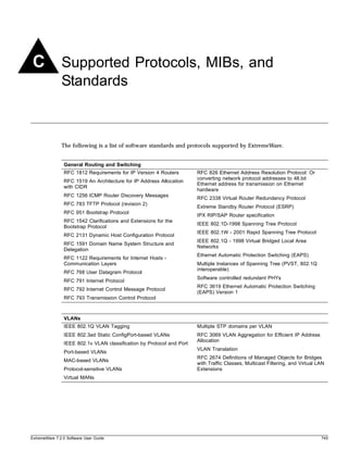
Supported MIBs
In addition to private MIBs, the switch supports the standard MIBs listed in Appendix C.
NOTE
The SNMP ifAdminStatus MIB value is not saved after a reboot. Ports set to down in the SNMP
ifAdminStatus MIB come back after rebooting. However, if you save the configuration using the CLI or
SNMP after changing the port status to down in the ifAdminStatus MIB, then the change is saved after
a reboot.
Configuring SNMPv1/v2c Settings
The following SNMPv1/v2c parameters can be configured on the switch:
• Authorized trap receivers—An authorized trap receiver can be one or more network management
stations on your network. The switch sends SNMPv1/v2c traps to all trap receivers. You can have a
maximum of 16 trap receivers configured for each switch, and you can specify a community string
and UDP port for individually for each trap receiver. All community strings must also be added to
the switch using the configure snmp add community command.
To configure a trap receiver on a switch, use the following command:
configure snmp add trapreceiver <ip address> {port <number>} community {hex}
<community string> {from <source ip address>} {mode [enhanced | standard]}
trap-group {auth-traps{,}} {bgp-traps{,}} {extreme-traps{,}}
{link-up-down-traps{,}} {ospf-traps{,} {ping-traceroute-traps{,}} {rmon-traps{,}}
{security-traps{,}} {smart-traps{,}} {stp-traps{,}} {system-traps{,}}
{vrrp-traps{,}}
See the Command Reference for a listing of the available traps.
You can delete a trap receiver using the configure snmp delete trapreceiver command.
Entries in the trap receiver list can also be created, modified, and deleted using the RMON2
trapDestTable MIB variable, as described in RFC 2021.
• SNMP read access—The ability to read SNMP information can be restricted through the use of an
access profile. An access profile permits or denies a named list of IP addresses and subnet masks.
To configure SNMPv1/v2c read access to use an access profile, use the following command:
configure snmp access-profile readonly [<access-profile> | none]
Use the none option to remove a previously configured access profile.
• SNMP read/write access—The ability to read and write SNMP information can be restricted through
the use of an access profile. An access profile permits or denies a named list of IP addresses and
subnet masks.
To configure SNMPv1/v2c read/write access to use an access profile, use the following command:
64 ExtremeWare 7.2.0 Software User Guide](https://image.slidesharecdn.com/extremewareuserguide72-110124002726-phpapp01/85/Extreme-wareuserguide72-64-320.jpg)
![Using SNMP
configure snmp access-profile readwrite [<access-profile> | none]
Use the none option to remove a previously configured access-profile.
• Community strings—The community strings allow a simple method of authentication between the
switch and the remote Network Manager. There are two types of community strings on the switch.
Read community strings provide read-only access to the switch. The default read-only community
string is public. Read-write community strings provide read and write access to the switch. The
default read-write community string is private.
• System contact (optional)—The system contact is a text field that enables you to enter the name of
the person(s) responsible for managing the switch.
• System name—The system name is the name that you have assigned to this switch. The default
name is the model name of the switch (for example, Summit1 switch).
• System location (optional)—Using the system location field, you can enter an optional location for
this switch.
• Enabling/disabling link up and link down traps (optional)—By default, link up and link down
traps (also called port-up-down traps) are enabled on the switch for all ports. SNMPv1 traps for link
up and link down are not supported; ExtremeWare uses SNMPv2 traps.
You can disable or re-enable the sending of these traps on a per port basis, by using the following
commands:
disable snmp traps port-up-down ports [all | mgmt | <portlist>]
enable snmp traps {port-up-down ports [all | mgmt | <portlist>]}
The mgmt option will only appear on platforms having a management port.
• Enabling/disabling exceed-committed-rate traps—By default these traps are disabled on the switch
for all ports. This command is available on “3” series I/O modules only.
You can disable or enable the sending of these traps on a per port basis, by using the following
command:
disable snmp traps exceed-committed-rate ports <portlist> {<Ingress QOS Profile>}
enable snmp traps exceed-committed-rate ports <portlist> {<Ingress QOS Profile>}
• Enabling/disabling MAC-security traps (optional)—MAC-security traps are sent on ports when
limit-learning is configured and a new MAC address appears on the port after the port has already
learned MAC addresses up to the configured limit. At such instants, a log message is generated in
the syslog, a trap is sent out and the port is blackholed. By default, MAC-security traps are disabled
on the switch. To enable or re-disable them, the following commands must be used:
enable snmp traps mac-security
disable snmp traps mac-security
NOTE
To configure learning limits on a set of ports, the command configure ports <portlist> limit-learning can
be used.
Displaying SNMP Settings
To display the SNMP settings configured on the switch, use the following command:
show management
This command displays the following information:
ExtremeWare 7.2.0 Software User Guide 65](https://image.slidesharecdn.com/extremewareuserguide72-110124002726-phpapp01/85/Extreme-wareuserguide72-65-320.jpg)
![Managing the Switch
• Enable/disable state for Telnet, SSH2, SNMP, and web access, along with access profile information
• SNMP community strings
• Authorized SNMP station list
• SNMP MAC-security traps
• Link up/ link down traps enabled on ports
• SNMP trap receiver list
• SNMP trap groups
• RMON polling configuration
• Login statistics
• Enable/disable status of link up and link down traps
• Enable/disable status of MAC-security traps
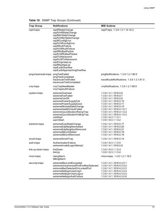
SNMP Trap Groups
SNMP trap groups allow you to specify which SNMP traps to send to a particular trap receiver. This
functionality was made possible by the underlying support for SNMPv3. Essentially, a number of
predefined filters are associated with a trap receiver, so that only those traps are sent. If you have
already been using SNMPv1/v2c trap receivers, trap groups are very easy to incorporate into your
network. You cannot define your own trap groups. If you need to define more selectively which
notifications to receive, you will need to use the notification filter capabilities available in SNMPv3.
To configure trap groups, use the following command:
configure snmp add trapreceiver <ip address> {port <number>} community {hex}
<community string> {from <source ip address>} {mode [enhanced | standard]} trap-group
{auth-traps{,}} {bgp-traps{,}} {extreme-traps{,}} {link-up-down-traps{,}}
{ospf-traps{,} {ping-traceroute-traps{,}} {rmon-traps{,}} {security-traps{,}}
{smart-traps{,}} {stp-traps{,}} {system-traps{,}} {vrrp-traps{,}}
For example, to send system and link up/link down traps to the receiver at 10.20.30.44 port 9347 with
the community string private, use the following command:
configure snmp add trapreceiver 10.20.30.44 port 9347 community private trap-group
link-up-down-traps , system-traps
Table 10 lists the currently defined SNMP trap groups. From time to time, new trap groups may be
added to this command.
Table 10: SNMP Trap Groups
Trap Group Notifications MIB Subtree
stp-traps newRoot dot1dBridge, 1.3.6.1.2.1.17
topologyChange
bgp-traps bgpEstablished bgpTraps, 1.3.6.1.2.1.15.7
bgpBackwardTransition
extremeBgpPrefixReachedThreshold extremeBgpTrapsPrefix, 1.3.6.1.4.1.1916.4.2.0
extremeBgpPrefixMaxExceeded
66 ExtremeWare 7.2.0 Software User Guide](https://image.slidesharecdn.com/extremewareuserguide72-110124002726-phpapp01/85/Extreme-wareuserguide72-66-320.jpg)
![Using SNMP
NOTE
In SNMPv3, many objects can be identified by a human-readable string or by a string of hex octets. In
many commands, you can use either a character string, or a colon separated string of hex octets to
specify objects. This is indicated by the keyword hex used in the command.
Message Processing
A particular network manager may require messages that conform to a particular version of SNMP. The
choice of the SNMPv1, SNMPv2, or SNMPv3 message processing model can be configured for each
network manager as its target address is configured. The selection of the message processing model is
configured with the mp-model keyword in the following command:
configure snmpv3 add target-params {hex} <param name> user {hex} <user name> mp-model
[snmpv1 | snmpv2c | snmpv3] sec-model [snmpv1 | snmpv2c | usm] {sec-level [noauth |
authnopriv | priv]} {volatile}
SNMPv3 Security
In SNMPv3 the User-Based Security Model (USM) for SNMP was introduced. USM deals with security
related aspects like authentication, encryption of SNMP messages and defining users and their various
access security levels. This standard also encompass protection against message delay and message
replay.
USM Timeliness Mechanisms
There is one SNMPv3 engine on an Extreme switch, identified by its snmpEngineID. The first four octets
are fixed to 80:00:07:7C, which represents the Extreme Networks Vendor ID. By default, the additional
octets for the snmpEngineID are generated from the device MAC address. Every SNMPv3 engine
necessarily maintains two objects: SNMPEngineBoots, which is the number of reboots the agent has
experienced and SNMPEngineTime, which is the engine local time since reboot. It has a local copy of
these objects and the latestReceivedEngineTime for every authoritative engine it wants to communicate
with. Comparing these objects with the values received in messages and then applying certain rules to
decide upon the message validity accomplish protection against message delay or message replay.
In a chassis, the snmpEngineID will be generated using the MAC address of the MSM with which the
switch boots first. For MSM hitless failover, the same snmpEngineID will be propagated to both of the
MSMs.
The snmpEngineID can be configured from the command line, but once the snmpEngineID is changed,
default users will be reverted back to their original passwords/keys, while non-default users will be
reset to the security level of no authorization, no privacy. Use the following command to set the
snmpEngineID:
configure snmpv3 engine-id <hex octet>
SNMPEngineBoots can also be configured from the command line. SNMPEngineBoots can be set to any
desired value but will latch on its maximum, 2147483647. Use the following command to set the
SNMPEngineBoots:
configure snmpv3 engine-boots <(1-2147483647)>
ExtremeWare 7.2.0 Software User Guide 69](https://image.slidesharecdn.com/extremewareuserguide72-110124002726-phpapp01/85/Extreme-wareuserguide72-69-320.jpg)
![Managing the Switch
Users, Groups, and Security
SNMPv3 controls access and security using the concepts of users, groups, security models, and security
levels.
Users. Users are created by specifying a user name. Depending on whether the user will be using
authentication and/or privacy, you would also specify an authentication protocol (MD5 or SHA) with
password or key, and/or privacy (DES) password or key. To create a user, use the following command:
configure snmpv3 add user {hex} <user name> {authentication [md5 | sha] [hex <hex
octet> | <password>]} {privacy [hex <hex octet> | <password>]} {volatile}
There are a number of default, permanent users initially available.The default user names are: admin,
initial, initialmd5, initialsha, initialmd5Priv, initialshaPriv. The default password for admin is password. For
the other default users, the default password is the user name.
To display information about a user, or all users, use the following command:
show snmpv3 user {{hex} <user name>}
To delete a user, use the following command:
configure snmpv3 delete user [all-non-defaults | {hex} <user name>]
NOTE
In the SNMPv3 specifications there is the concept of a security name. In the ExtremeWare
implementation, the user name and security name are identical. In this manual we use both terms to
refer to the same thing.
Groups. Groups are used to manage access for the MIB. You use groups to define the security model,
the security level, and the portion of the MIB that members of the group can read or write. To
underscore the access function of groups, groups are defined using the following command:
configure snmpv3 add access {hex} <group name> {sec-model [snmpv1 | snmpv2 | usm]}
{sec-level [noauth | authnopriv | authpriv]} {read-view {hex} <view name>} {
write-view {hex} <view name>} {notify-view {hex} <view name>} {volatile}
The security model and security level are discussed in the section labeled “Security Models and Levels”.
The view names associated with a group define a subset of the MIB (subtree) that can be accessed by
members of the group. The read view defines the subtree that can be read, write view defines the
subtree that can be written to, and notify view defines the subtree that notifications can originate from.
MIB views are discussed in the section “MIB Access Control”.
There are a number of default (permanent) groups already defined. These groups are: admin, initial,
initialmd5, initialsha, initialmd5Priv, initialshaPriv, v1v2c_ro, v1v2c_rw. Use the following command to
display information about the access configuration of a group or all groups:
show snmpv3 access {{hex} <group name>}
Users are associated with groups using the following command:
configure snmpv3 add group {hex} <group name> user {hex} <user name> {sec-model
[snmpv1| snmpv2 | usm]} {volatile}
To show which users are associated with a group, use the following command:
70 ExtremeWare 7.2.0 Software User Guide](https://image.slidesharecdn.com/extremewareuserguide72-110124002726-phpapp01/85/Extreme-wareuserguide72-70-320.jpg)
![Using SNMP
show snmpv3 group {{hex} <group name> {user {hex} <user name>}}
To delete a group, use the following command:
configure snmpv3 delete access [all-non-defaults | {{hex} <group name>
{sec-model [snmpv1 | snmpv2c | usm] sec-level [noauth | authnopriv |
priv]}}]
When you delete a group, you do not remove the association between the group. To delete the
association between a user and a group, use the following command:
configure snmpv3 delete group {{hex} <group name>} user [all-non-defaults | {{hex}
<user name> {sec-model [snmpv1|snmpv2c|usm]}}]
Security Models and Levels. For compatibility, SNMPv3 supports three security models:
• SNMPv1—no security
• SNMPv2c—community strings based security
• SNMPv3—USM security
The default is User-Based Security Model (USM). You can select the security model based on the
network manager in your network.
The three security levels supported by USM are:
• noAuthnoPriv—No authentication, no privacy. This is the case with existing SNMPv1/v2c agents.
• AuthnoPriv—Authentication, no privacy. Messages are tested only for authentication.
• AuthPriv—Authentication, privacy. This represents the highest level of security and requires every
message exchange to pass the authentication and encryption tests.
When a user is created, an authentication method is selected, and the authentication and privacy
passwords or keys are entered.
When MD5 authentication is specified, HMAC-MD5-96 is used to achieve authentication with a 16-octet
key, which generates an 128-bit authorization code. This code is inserted in
msgAuthenticationParameters field of SNMPv3 PDUs when the security level is specified as either
AuthnoPriv or AuthPriv. Specifying SHA authentication uses the HMAC-SHA protocol with a 20-octet
key for authentication.
For privacy, a 16-octet key is provided as input to DES-CBS encryption protocol, which generates an
encrypted PDU to be transmitted. DES uses bytes 1-7 to make a 56 bit key. This key (encrypted itself) is
placed in msgPrivacyParameters of SNMPv3 PDUs when the security level is specified as AuthPriv.
MIB Access Control
SNMPv3 provides a fine-grained mechanism for defining which parts of the MIB can be accessed. This
is referred to as the View-Based Access Control Model (VACM).
MIB views represent the basic building blocks of VACM. They are used to define a subset of the
information in the MIB. Access to read, to write, and to generate notifications is based on the
relationship between a MIB view and an access group. The users of the access group can then read,
write, or receive notifications from the part of the MIB defined in the MIB view as configured in the
access group.
ExtremeWare 7.2.0 Software User Guide 71](https://image.slidesharecdn.com/extremewareuserguide72-110124002726-phpapp01/85/Extreme-wareuserguide72-71-320.jpg)
![Managing the Switch
A view name, a MIB subtree/mask, and an inclusion or exclusion define every MIB view. For example,
there is a System group defined under the MIB-2 tree. The Object Identifier (OID) for MIB-2 is 1.3.6.1.2,
and the System group is defined as MIB-2.1.1, or directly as 1.3.6.1.2.1.1.
To define a MIB view which includes only the System group, use the following subtree/mask
combination:
1.3.6.1.2.1.1 / 1.1.1.1.1.1.1.0
The mask can also be expressed in hex notation (this is used for the ExtremeWare CLI):
1.3.6.1.2.1.1 / fe
To define a view that includes the entire MIB-2, use the following subtree/mask:
1.3.6.1.2.1.1 / 1.1.1.1.1.0.0.0
which, on the command line, is:
1.3.6.1.2.1.1 / f8
When you create the MIB view, you can choose to include the MIB subtree/mask, or to exclude the MIB
subtree/mask. To create a MIB view, use the following command:
configure snmpv3 add mib-view {hex} <view name> subtree <object identifier> {/<subtree
mask>} {type [included | excluded]} {volatile}
Once the view is created, you can repeatedly use the configure snmpv3 add mib-view command to
include and/or exclude MIB subtree/mask combinations to precisely define the items you wish to
control access to.
In addition to the user created MIB views, there are three default views. They are of storage type
permanent and cannot be deleted, but they can be modified. The default views are: defaultUserView,
defaultAdminView, and defaultNotifyView. To show MIB views, use the following command:
show snmpv3 mib-view {{hex} <view name> {subtree <object identifier>}}
To delete a MIB view, use the following command:
configure snmpv3 delete mib-view [all-non-defaults | {{hex} <view name> {subtree
<object identifier>}}]
MIB views which are being used by security groups cannot be deleted.
Notification
SNMPv3 notification is an enhancement to the concept of SNMP traps. Notifications are messages sent
from an agent to the network manager, typically in response to some state change on the agent system.
With SNMPv3, you can define precisely which traps you want sent, to which receiver by defining filter
profiles to use for the notification receivers.
To configure notifications, you will configure a target address for the process that receives the
notification, a target parameters name, and a list of notification tags. The target parameters specify the
security and message processing models to use for the notifications to the target. The target parameters
name also points to the filter profile used to filter the notifications. Finally, the notification tags are
added to a notification table so that any target addresses using that tag will receive notifications.
72 ExtremeWare 7.2.0 Software User Guide](https://image.slidesharecdn.com/extremewareuserguide72-110124002726-phpapp01/85/Extreme-wareuserguide72-72-320.jpg)
![Using SNMP
Target Addresses
A target address is similar to the earlier concept of a trap receiver. To configure a target address, use the
following command:
configure snmpv3 add target-addr {hex} <addr name> param {hex} <param name> ipaddress
<ip address> {transport-port <port>} {from <source IP address>} {tag-list {hex} <tag>,
{hex} <tag>, ...} {volatile}
In configuring the target address you will supply an address name that will be used to identify the
target address, a parameters name that will indicate the message processing model and security for the
messages sent to the target address, and the IP address and port for the receiver. The parameters name
also is used to indicate the filter profile used for notifications. The target parameters will be discussed in
the section “Target Parameters”.
The from option sets the source IP address in the notification packets.
The tag-list option allows you to associate a list of tags with the target address. The tag defaultNotify
is set by default. Tags are discussed in the section “Notification Tags”.
To display target addresses, use the following command:
show snmpv3 target-addr {{hex} <addr name>}
To delete a single target address or all target addresses, use the following command:
configure snmpv3 delete target-addr [{{hex} <addr name>} | all]
Target Parameters
Target parameters specify the message processing model, security model, security level, and user name
(security name) used for messages sent to the target address. See the sections “Message Processing” and
“Users, Groups, and Security” for more details on these topics. In addition, the target parameter name
used for a target address points to a filter profile used to filter notifications. When you specify a filter
profile, you will associate it with a parameter name, so you will need to create different target
parameter names if you will use different filters for different target addresses.
Use the following command to create a target parameter name, and set the message processing and
security settings associated with it:
configure snmpv3 add target-params {hex} <param name> user {hex} <user name> mp-model
[snmpv1 | snmpv2c | snmpv3] sec-model [snmpv1 | snmpv2c | usm] {sec-level [noauth |
authnopriv | priv]} {volatile}
To display the options associated with a target parameters name, or all target parameters names, use the
following command:
show snmpv3 target-params {{hex} <param name>}
To delete one or all the target parameters, use the following command:
configure snmpv3 delete target-params [{{hex} <param name>} | all]
Filter Profiles and Filters
A filter profile is a collection of filters that specifies which notifications should be sent to a target
address. A filter is defined by a MIB subtree and mask, and by whether that subtree and mask is
included or excluded from notification.
ExtremeWare 7.2.0 Software User Guide 73](https://image.slidesharecdn.com/extremewareuserguide72-110124002726-phpapp01/85/Extreme-wareuserguide72-73-320.jpg)
![Managing the Switch
When you create a filter profile, you are only associating a filter profile name with a target parameter
name. The filters that make up the profile are created and associated with the profile using a different
command. To create a filter profile, use the following command:
configure snmpv3 add filter-profile {hex} <profile name> param {hex} <param name>
{volatile}
Once the profile name is created, you can associate filters with it using the following command:
configure snmpv3 add filter {hex} <profile name> subtree <object identifier>
{/<subtree mask>} type [included | excluded] {volatile}
The MIB subtree and mask are discussed in the section “MIB Access Control”, as filters are closely
related to MIB views. You can add filters together, including and excluding different subtrees of the MIB
until your filter meets your needs.
To display the association between parameter names and filter profiles, use the following command:
show snmpv3 filter-profile {{hex} <profile name>} {param {hex} <param name>}
To display the filters that belong a filter profile, use the following command:
show snmpv3 filter {{hex} <profile name> {{subtree} <object identifier>}
To delete a filter or all filters from a filter profile, use the following command:
configure snmpv3 delete filter [all | [{hex} <profile name> {subtree <object
identifier>}]]
To remove the association of a filter profile or all filter profiles with a parameter name, use the
following command:
configure snmpv3 delete filter-profile [all |[{hex}<profile name> {param {hex}<param
name>}]]
Notification Tags
When you create a target address, you associate a list of notification tags with the target, or by default,
the defaultNotify tag is associated with the target. When notifications are generated, only targets
associated with tags currently in an internal structure, called snmpNotifyTable, will be notified. To add an
entry to the table, use the following command:
configure snmpv3 add notify {hex} <notify name> tag {hex} <tag> {volatile}
Any targets associated with tags in the snmpNotifyTable will be notified, based on the filter profile
associated with the target.
To display the notifications that are set, use the following command:
show snmpv3 notify {{hex} <notify name>}
To delete an entry from the snmpNotifyTable, use the following command:
configure snmpv3 delete notify [{{hex} <notify name>} | all-non-defaults]
You cannot delete the default entry from the table, so any targets configured with the defaultNotify tag
will always receive notifications consistent with any filter profile specified.
74 ExtremeWare 7.2.0 Software User Guide](https://image.slidesharecdn.com/extremewareuserguide72-110124002726-phpapp01/85/Extreme-wareuserguide72-74-320.jpg)
![Managing the Switch
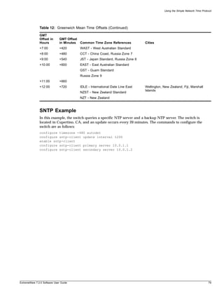
Using the Simple Network Time Protocol
ExtremeWare supports the client portion of the Simple Network Time Protocol (SNTP) Version 3 based
on RFC1769. SNTP can be used by the switch to update and synchronize its internal clock from a
Network Time Protocol (NTP) server. When enabled, the switch sends out a periodic query to the
indicated NTP server, or the switch listens to broadcast NTP updates. In addition, the switch supports
the configured setting for Greenwich Mean time (GMT) offset and the use of Daylight Saving Time.
These features have been tested for year 2000 compliance.
Configuring and Using SNTP
To use SNTP, follow these steps:
1 Identify the host(s) that are configured as NTP server(s). Additionally, identify the preferred method
for obtaining NTP updates. The options are for the NTP server to send out broadcasts, or for
switches using NTP to query the NTP server(s) directly. A combination of both methods is possible.
You must identify the method that should be used for the switch being configured.
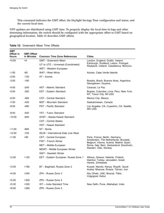
2 Configure the Greenwich Mean Time (GMT) offset and Daylight Saving Time preference. The
command syntax to configure GMT offset and usage of Daylight Saving Time is as follows:
configure timezone {name <std_timezone_ID>} <GMT_offset> {autodst {name
<dst_timezone_ID>} {<dst_offset>} {begins [every <floatingday> | on <absoluteday>]
{at <time_of_day>} {ends [every <floatingday> | on <absoluteday>] {at
<time_of_day>}}} | noautodst}
By default, Daylight Saving Time is assumed to begin on the first Sunday in April at 2:00 AM, and
end the last Sunday in October at 2:00 AM, and be offset from standard time by one hour. If this is
the case in your timezone, you can set up automatic daylight savings adjustment with the command:
configure timezone <GMT_offset> autodst
If your timezone uses starting and ending dates and times that differ from the default, you can
specify the starting and ending date and time in terms of a floating day, as follows:
configure timezone name MET 60 autodst name MDT begins every last sunday march at
1 ends every last sunday october at 1
You can also specify a specific date and time, as shown in the following command.
configure timezone name NZST 720 autodst name NZDT 60 begins every first sunday
october at 2 ends on 3/16/2002 at 2
The optional timezone IDs are used to identify the timezone in display commands such as show
switch.
Table 11 describes the command options in detail:
Table 11: Time Zone Configuration Command Options
GMT_offset Specifies a Greenwich Mean Time (GMT) offset, in + or - minutes.
std-timezone-ID Specifies an optional name for this timezone specification. May be up to six characters in
length. The default is an empty string.
autodst Enables automatic Daylight Savings Time.
dst-timezone-ID Specifies an optional name for this DST specification. May be up to six characters in
length. The default is an empty string.
dst_offset Specifies an offset from standard time, in minutes. Value is in the range of 1 to 60.
Default is 60 minutes.
76 ExtremeWare 7.2.0 Software User Guide](https://image.slidesharecdn.com/extremewareuserguide72-110124002726-phpapp01/85/Extreme-wareuserguide72-76-320.jpg)
![Using the Simple Network Time Protocol
Table 11: Time Zone Configuration Command Options (Continued)
floating_day Specifies the day, week, and month of the year to begin or end DST each year. Format is:
<week><day><month> where:
• <week> is specified as [first | second | third | fourth | last] or 1-5
• <day> is specified as [sunday | monday | tuesday | wednesday | thursday | friday |
saturday] or 1-7 (where 1 is Sunday)
• <month> is specified as [january | february | march | april | may | june | july | august |
september | october | november | december] or 1-12
Default for beginning is first sunday april; default for ending is last sunday october.
absolute_day Specifies a specific day of a specific year on which to begin or end DST. Format is:
<month>/<day>/<year> where:
• <month> is specified as 1-12
• <day> is specified as 1-31
• <year> is specified as 1970 - 2035
The year must be the same for the begin and end dates.
time_of_day Specifies the time of day to begin or end Daylight Savings Time. May be specified as an
hour (0-23) or as hour:minutes. Default is 2:00.
noautodst Disables automatic Daylight Savings Time.
Automatic Daylight Savings Time (DST) changes can be enabled or disabled. The default setting is
enabled. To disable automatic DST, use the command:
configure timezone {name <std_timezone_ID>} <GMT_offset> noautodst
3 Enable the SNTP client using the following command:
enable sntp-client
Once enabled, the switch sends out a periodic query to the NTP servers defined later (if configured)
or listens to broadcast NTP updates from the network. The network time information is
automatically saved into the on-board real-time clock.
4 If you would like this switch to use a directed query to the NTP server, configure the switch to use
the NTP server(s). If the switch listens to NTP broadcasts, skip this step. To configure the switch to
use a directed query, use the following command:
configure sntp-client [primary | secondary] server <host name/ip>]
NTP queries are first sent to the primary server. If the primary server does not respond within 1
second, or if it is not synchronized, the switch queries the secondary server (if one is configured). If
the switch cannot obtain the time, it restarts the query process. Otherwise, the switch waits for the
sntp-client update interval before querying again.
5 Optionally, the interval for which the SNTP client updates the real-time clock of the switch can be
changed using the following command:
configure sntp-client update-interval <seconds>
The default sntp-client update-interval value is 64 seconds.
6 You can verify the configuration using the following commands:
— show sntp-client
This command provides configuration and statistics associated with SNTP and its connectivity to
the NTP server.
— show switch
ExtremeWare 7.2.0 Software User Guide 77](https://image.slidesharecdn.com/extremewareuserguide72-110124002726-phpapp01/85/Extreme-wareuserguide72-77-320.jpg)

![Configuring Ports on a Switch
Configuring Ports on a Switch
On a modular switch, the port number is a combination of the slot number and the port number. The
nomenclature for the port number is as follows:
slot:port
For example, if a G4X I/O module (having a total of four ports) is installed in slot 2 of the
BlackDiamond 6808 chassis, the following ports are valid:
• 2:1
• 2:2
• 2:3
• 2:4
You can also use wildcard combinations (*) to specify multiple modular slot and port combinations. The
following wildcard combinations are allowed:
• slot:*—Specifies all ports on a particular I/O module.
• slot:x-slot:y—Specifies a contiguous series of ports on a particular I/O module.
• slota:x-slotb:y—Specifies a contiguous series of ports that begin on one I/O module and end on
another I/O module.
Enabling and Disabling Switch Ports
By default, all ports are enabled. To enable or disable one or more ports on a modular switch, use the
following command:
enable ports [<portlist> | all]
disable ports [<portlist> | all]
To enable or disable one or more ports on a stand-alone switch, use the following command:
enable ports [<portlist> | all]
disable ports [<portlist> | all]
For example, to disable slot 7, ports 3, 5, and 12 through 15 on a modular switch, use the following
command:
disable ports 7:3,7:5,7:12-7:15
For example, to disable ports 3, 5, and 12 through 15 on a stand-alone switch, use the following
command:
disable ports 3,5,12-15
Even though a port is disabled, the link remains enabled for diagnostic purposes.
Configuring Switch Port Speed and Duplex Setting
By default, the switch is configured to use autonegotiation to determine the port speed and duplex
setting for each port. You can manually configure the duplex setting and the speed of 10/100 Mbps
ports, and you can manually configure the duplex setting of Gigabit Ethernet ports.
ExtremeWare 7.2.0 Software User Guide 83](https://image.slidesharecdn.com/extremewareuserguide72-110124002726-phpapp01/85/Extreme-wareuserguide72-83-320.jpg)
![Configuring Slots and Ports on a Switch
10BASE-T and 100BASE-TX ports can connect to either 10BASE-T or 100BASE-T networks. By default,
the ports autonegotiate port speed. You can also configure each port for a particular speed (either 10
Mbps or 100 Mbps).
Gigabit Ethernet ports are statically set to 1 Gbps, and their speed cannot be modified.
VDSL ports default to 10 Mbps, and their speed can be configured as 5 Mbps, 10 Mbps, or to support
the European Telecommunications Standards Institute (ETSI) VDSL standard, ETSI Plan 997. To
configure VDSL ports, use the following command:
configure ports <portlist> vdsl [5meg | 10meg | etsi]
All ports on a stand-alone switch can be configured for half-duplex or full-duplex operation. By default,
the ports autonegotiate the duplex setting.
To configure port speed and duplex setting, use the following command:
configure ports [<portlist> | all | mgmt] auto off {speed [10 | 100 | 1000]} duplex
[half | full]
To configure the system to autonegotiate, use the following command:
configure ports [<portlist> | mgmt | all] auto on
Flow control is fully supported only on Gigabit Ethernet ports. Gigabit ports both advertise support and
respond to pause frames. 10/100 Mbps Ethernet ports also respond to pause frames, but do not
advertise support. Neither 10/100 Mbps or Gigabit Ethernet ports initiate pause frames.
Flow Control is enabled or disabled as part of autonegotiation. If autonegotiation is set to off, flow
control is disabled. When autonegotiation is turned on, flow control is enabled.
Turning Off Autonegotiation for a Gigabit Ethernet Port
In certain interoperability situations, you may need to turn autonegotiation off on a Gigabit Ethernet
port. Even though a Gigabit Ethernet port runs only at full duplex, you must specify the duplex setting.
NOTE
1000BASE-TX ports support only autonegotiation.
The following example turns autonegotiation off for port 1 on a G4X or G6X module located in slot 1 of
a modular switch:
configure ports 1:1 auto off duplex full
The following example turns autonegotiation off for port 4 (a Gigabit Ethernet port) on a stand-alone
switch:
configure ports 4 auto off duplex full
Turning Off Autopolarity Detection for an Ethernet Port
The autopolarity feature on the Summit48si switch allows the system to detect and respond to the
Ethernet cable type (straight-through vs. crossover cable) used to make the connection to the switch
port. When the autopolarity feature is enabled, the system causes the Ethernet link to come up
regardless of the cable type connected to the port. When the autopolarity feature is disabled, the link
84 ExtremeWare 7.2.0 Software User Guide](https://image.slidesharecdn.com/extremewareuserguide72-110124002726-phpapp01/85/Extreme-wareuserguide72-84-320.jpg)
![Configuring Ports on a Switch
will come up only when a crossover cable is connected to the port. The autopolarity feature is
supported only on the 10BASE-T and 100BASE-TX switch ports, and enabled by default.
To disable or enable autopolarity detection, use the following command:
configure ports [<portlist> | all] auto-polarity [off | on]
where the following is true:
• portlist—Specifies one or more ports on the switch
• all—Specifies all of the ports on the switch
• off—Disables the autopolarity detection feature on the specified ports
• on—Enables the autopolarity detection feature on the specified ports
Under certain conditions, you might opt to turn autopolarity off on one or more 10BASE-T and
100BASE-TX ports. The following example turns autopolarity off for ports 3-5 on a Summit48si switch:
configure ports 3-5 auto-polarity off
NOTE
If you attempt to invoke this command on a Gigabit Ethernet switch port, the system displays a
message indicating that the specified port is not supported by this feature.
When autopolarity is disabled on one or more Ethernet ports, you can verify that status by using the
command:
show configuration
This command will list the ports for which the feature has been disabled.
You can also verify the current autopolarity status by using the command:
show ports {mgmt | <portlist>} info {detail}
Configuring Link Detection
ExtremeWare contains an interrupt service routine (ISR) that sends interrupts when links transition. If a
link continuously transitions, causing the ISR to send continuous interrupts, the middle layer filter
filters out the continuous interrupt messages. You can configure the interaction between these functions
using the following command:
configure ports <portlist> link-detection-level <link-detection-level>
Configuring Interpacket Gap for 10 Gigabit Ethernet Ports
You can configure the Interpacket Gap for 10 Gigabit Ethernet ports only. The Interpacket Gap,
sometimes referred to as the Interframe Gap, is the transmit packet byte-time delay between successive
data packets mandated by the IEEE for Ethernet networks. Byte-time is the amount of time it takes to
transmit one byte on the link at the specified or negotiated link speed. The configured Interpacket Gap
value has no effect on received packets. The default value is 16. The minimum and maximum allowed
values range between 12 and 1023.
ExtremeWare 7.2.0 Software User Guide 85](https://image.slidesharecdn.com/extremewareuserguide72-110124002726-phpapp01/85/Extreme-wareuserguide72-85-320.jpg)
![Configuring Slots and Ports on a Switch
The standard effective Interpacket Gap for 10 Gigabit Ethernet interfaces ranges between 12 and 1023.
Some vendors' 10 Gigabit Ethernet interfaces drop packets when packets are transmitted using a value
of 12. Thus, by increasing the Interpacket Gap, packet transmission is slowed and packet loss can be
minimized or prevented. The Interpacket Gap value need not be modified when interconnecting
Extreme Networks switches over 10 Gigabit Ethernet links. Use the following command to modify the
Interpacket Gap:
configure port <slot:port> interpacket-gap <byte_time>
Jumbo Frames
Jumbo frames are Ethernet frames that are larger than 1522 bytes, including four bytes used for the cyclic
redundancy check (CRC). Extreme products support switching and routing of jumbo frames at
wire-speed on all ports.
Jumbo frames are used between endstations that support larger frame sizes for more efficient transfers
of bulk data. Both endstations involved in the transfer must be capable of supporting jumbo frames.
The switch only performs IP fragmentation, or participates in maximum transmission unit (MTU)
negotiation on behalf of devices that support jumbo frames.
Enabling Jumbo Frames
To enable jumbo frame support, enable jumbo frames on the desired ports. To set the maximum jumbo
frame size, use the following command:
configure jumbo-frame size <number>
The jumbo frame size range is 1523 to 9216. This value describes the maximum size of the frame in
transit (on the wire), and includes 4 bytes of CRC plus another 4 bytes if 802.1Q tagging is being used.
Set the MTU size for the VLAN, using the following command:
configure ip-mtu <number> vlan <vlan name>
The IP MTU default is 1500. The range is 1500-9194.
NOTE
PoS or ATM must be rebooted if the IP-MTU configuration is changed.
Next, enable support on the physical ports that will carry jumbo frames using the following command:
enable jumbo-frame ports [<portlist> | all]
NOTE
Some network interface cards (NICs) have a configured maximum MTU size that does not include the
additional 4 bytes of CRC. Ensure that the NIC maximum MTU size is at or below the maximum MTU
size configured on the switch. Frames that are larger than the MTU size configured on the switch are
dropped at the ingress port.
86 ExtremeWare 7.2.0 Software User Guide](https://image.slidesharecdn.com/extremewareuserguide72-110124002726-phpapp01/85/Extreme-wareuserguide72-86-320.jpg)
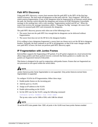
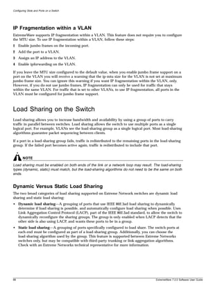
![Load Sharing on the Switch
Load-Sharing Algorithms
Load-sharing algorithms allow you to select the distribution technique used by the load-sharing group
to determine the output port selection. Algorithm selection is not intended for use in predictive traffic
engineering. You can only choose the algorithm used in static load sharing, as dynamic load sharing
exclusively uses an address-based algorithm.
You can configure one of three load-sharing algorithms on the switch, as follows:
• Port-based—Uses the ingress port to determine which physical port in the load-sharing group is
used to forward traffic out of the switch.
• Address-based—Uses addressing information to determine which physical port in the load-sharing
group to use for forwarding traffic out of the switch. Addressing information is based on the packet
protocol, as follows:
— IP packets—Uses the source and destination MAC and IP addresses, and the TCP port number.
— IPX packets—Uses the source and destination MAC address, and IPX network identifiers.
— All other packets—Uses the source and destination MAC address.
• Round-robin—When the switch receives a stream of packets, it forwards one packet out of each
physical port in the load-sharing group using a round-robin scheme.
NOTE
Using the round-robin algorithm, packet sequencing between clients is not guaranteed.
If you do not explicitly select an algorithm, the port-based scheme is used. However, the address-based
algorithm has a more even distribution and is the recommended choice, except when running MPLS, in
which case port-based is recommended.
Configured IP Address-Based Load Sharing
When you configure load sharing, the switch examines a specific place in the packet to determine which
egress port to use for forwarding traffic:
• For layer 2 load sharing, the switch uses the MAC source address and destination address.
• For layer 3 load sharing, the switch uses the MAC source address and destination address, and the
IP source address and destination address.
• For layer 4 load sharing, the switch using the MAC source address and destination address, the IP
source address and destination address, and the UDP or TCP well-known port number.
You can control the field examined by the switch for IP address-based load sharing, using the following
command:
configure sharing address-based [L2 | L2_L3 | L2_L3_L4]
where:
• L2—Indicates that the switch should examine the MAC source and destination address.
• L3—Indicates that the switch should examine the MAC source address and destination address, and
the IP source address and destination address.
• L4—Indicates that the switch should examine the MAC source address and destination address, the
IP source address and destination address, and the UDP or TCP well-known port number.
ExtremeWare 7.2.0 Software User Guide 89](https://image.slidesharecdn.com/extremewareuserguide72-110124002726-phpapp01/85/Extreme-wareuserguide72-89-320.jpg)
![Configuring Slots and Ports on a Switch
This feature is available for the address-based load-sharing algorithm, only.
To verify your configuration, use the following command:
show sharing address-based
Configuring Switch Load Sharing
To set up a switch to load share among ports, you must create a load-sharing group of ports. The first
port in the load-sharing group is configured to be the “master” logical port. This is the reference port
used in configuration commands. It can be thought of as the logical port representing the entire port
group.
All the ports in a load-sharing group must have the same exact configuration, including auto
negotiation, duplex setting, ESRP host attach (HA) or don’t-count, and so on. All the ports in a
load-sharing group must also be of the same bandwidth class.
The following rules apply:
• One group can contain up to 8 ports.
• The ports in the group do not need to be contiguous.
• If dynamic load sharing is used (LACP), the ports in the group must be on the same I/O module.
• A load share group that spans multiple modules must use ports that are all of the same maximum
bandwidth capability.
• When using load sharing with the ESRP HA feature, configure all ports in the same load-sharing
group as host attach ports. When using load sharing with the ESRP don’t count feature, configure all
ports in the same load-sharing group as don’t count ports.
On BlackDiamond 6804 and 6808 chassis, the following limitation applies:
• The chassis must use the MSM-3 if you are going to configure a load share group that spans multiple
modules (cross-module trunking).
On BlackDiamond 6816 chassis, the following limitation applies:
• The ports in the group must be on the same I/O module.
To define a load-sharing group, you assign a group of ports to a single, logical port number. To enable
or disable a load-sharing group, use the following commands:
enable sharing <port> grouping <portlist> {dynamic | algorithm {port-based |
address-based | round-robin}}
disable sharing [<port>]
NOTE
Do not disable a port that is part of a load-sharing group. Disabling the port prevents it from forwarding
traffic, but still allows the link to initialize. As a result, a partner switch does not receive a valid indication
that the port is not in a forwarding state, and the partner switch will continue to forward packets.
90 ExtremeWare 7.2.0 Software User Guide](https://image.slidesharecdn.com/extremewareuserguide72-110124002726-phpapp01/85/Extreme-wareuserguide72-90-320.jpg)
![Load Sharing on the Switch
NOTE
BlackDiamond modules implement local switching; packets that ingress and egress on the same module
are not passed to the chassis backplane but switched on the module from the ingress to the egress
port. For this reason, packets arriving on a module that contains any of the configured cross-module
load sharing ports will only be shared with the ports on that module, and not with the ports on any other
modules.
Loopback Detection
Each port may enable loop detection. This optional feature detects that a port has been looped back to
the local system. If a loopback is detected, the port is disabled. Note that loopbacks may exist between
different ports. The feature will disable any port that both has the feature enabled, and receives an
LACP message that was sent from the local system.
To enable or disable loopback detection, use the following commands:
enable lbdetect port <portlist> [retry-timeout<seconds>]
disable lbdetect port <portlist>
Load-Sharing Examples
This section provides examples of how to define load-sharing on modular and stand-alone switches.
Cross-Module Load Sharing on a Modular Switch
Cross-module load sharing is available on Alpine chassis, and on BlackDiamond 6804 and 6808 chassis
that use the MSM-3. The following example defines a load-sharing group that contains ports 9 through
12 on slot 3, ports 7 through 10 on slot 5, and uses the first port in the slot 3 group as the master logical
port 9:
enable sharing 3:9 grouping 3:9-3:12, 5:7-5:10
In this example, logical port 3:9 represents physical ports 3:9 through 3:12 and 5:7 through 5:10.
When using load sharing, you should always reference the master logical port of the load-sharing group
(port 3:9 in the previous example) when configuring or viewing VLANs. VLANs configured to use
other ports in the load-sharing group will have those ports deleted from the VLAN when load sharing
becomes enabled.
For BlackDiamond chassis, packets are locally switched when possible, even with load sharing enabled.
For example, in the configuration above, packets received on port 3:2 that are destined for the
load-sharing group will only be shared with the ports 3:9-3:12 and not with ports 5:7-5:10. In contrast,
packets received on port 2:2 that are destined for the load-sharing group will be shared with the all the
ports in the load-sharing group (ports 3:9-3:12 and 5:7-5:10).
Single-Module Load Sharing on a Modular Switch
Single-module load sharing is supported on all modular switches. The BlackDiamond 6816 chassis, and
the BlackDiamond 6804 and 6808 chassis without the MSM-3, support only single-module load sharing.
The following example defines a load-sharing group that contains ports 9 through 12 on slot 3 and uses
the first port as the master logical port 9:
ExtremeWare 7.2.0 Software User Guide 91](https://image.slidesharecdn.com/extremewareuserguide72-110124002726-phpapp01/85/Extreme-wareuserguide72-91-320.jpg)
![Configuring Slots and Ports on a Switch
enable sharing 3:9 grouping 3:9-3:12
In this example, logical port 3:9 represents physical ports 3:9 through 3:12.
When using load sharing, you should always reference the master logical port of the load-sharing group
(port 3:9 in the previous example) when configuring or viewing VLANs. VLANs configured to use
other ports in the load-sharing group will have those ports deleted from the VLAN when load sharing
becomes enabled.
Load Sharing on a Stand-Alone Switch
The following example defines a load-sharing group that contains ports 9 through 12, and uses the first
port in the group as the master logical port 9:
enable sharing 9 grouping 9-12
In this example, logical port 9 represents physical ports 9 through 12.
When using load sharing, you should always reference the master logical port of the load-sharing group
(port 9 in the previous example) when configuring or viewing VLANs. VLANs configured to use other
ports in the load-sharing group will have those ports deleted from the VLAN when load sharing
becomes enabled.
NOTE
Do not disable a port that is part of a load-sharing group. Disabling the port prevents it from forwarding
traffic, but still allows the link to initialize. As a result, a partner switch does not receive a valid indication
that the port is not in a forwarding state, and the partner switch will continue to forward packets.
Verifying the Load-Sharing Configuration
The screen output resulting from the show ports sharing command lists the ports that are involved in
load sharing and the master logical port identity.
Performance Enhancements for Load Sharing
You can modify the backplane load-sharing policy on BlackDiamond switches to enhance performance.
The default backplane load-sharing policy is port-based. Selecting a policy for a particular situation will
depend on the type of traffic and network topology, however, for many situations an address-based
policy will enhance performance over other policies. You must save for changes to be saved across
reboots.
To configure the switch backplane load-sharing policy, use the following command:
configure backplane-ls-policy [address-based | port-based | round-robin]
and specify the following:
• address-based—address-based load-sharing algorithm
• port-based—port-based load-sharing algorithm
• round-robin—round-robin load-sharing algorithm
92 ExtremeWare 7.2.0 Software User Guide](https://image.slidesharecdn.com/extremewareuserguide72-110124002726-phpapp01/85/Extreme-wareuserguide72-92-320.jpg)
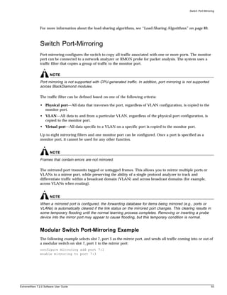
![Configuring Slots and Ports on a Switch
The following example sends all traffic coming into or out of the system on slot 8, port 1 and the VLAN
default to the mirror port:
enable mirroring to port 8:4
configure mirroring add port 8:1 vlan default
Stand-alone Switch Port-Mirroring Example
The following example selects port 3 as the mirror port and sends all traffic coming into or out of the
switch on port 1 to the mirror port:
enable mirroring to port 3
configure mirroring add port 1
The following example sends all traffic coming into or out of the switch on port 1 and the VLAN default
to the mirror port:
configure mirroring add port 1 vlan default
Extreme Discovery Protocol
The Extreme Discovery Protocol (EDP) is used to gather information about neighbor Extreme Networks
switches. EDP is used to by the switches to exchange topology information. EDP is also used by the
Extreme Standby Router Protocol (ESRP), described in Chapter 15. Information communicated using
EDP includes:
• Switch MAC address (switch ID).
• Switch software version information.
• Switch IP address.
• Switch VLAN-IP information.
• Switch port number.
EDP is enabled on all ports by default.
To disable EDP on one or more ports, use the following command:
disable edp ports [<portlist> | all]
To enable EDP on specified ports, use the following command:
enable edp ports [<portlist> | all]
To view EDP port information on the switch, use the following command:
show edp
Software-Controlled Redundant Port and
Smart Redundancy
Using the software-controlled redundant port feature you can back up a specified Ethernet port
(primary) with a redundant, dedicated Ethernet port (backup). If the primary port fails, the switch will
establish a link on the backup port and the backup port becomes active.
94 ExtremeWare 7.2.0 Software User Guide](https://image.slidesharecdn.com/extremewareuserguide72-110124002726-phpapp01/85/Extreme-wareuserguide72-94-320.jpg)
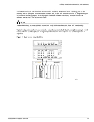
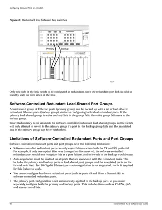
![Software-Controlled Redundant Port and Smart Redundancy
• The port speeds of software controlled redundant ports must be identical.
• You can configure only one redundant port for each primary port.
• You cannot load share two physical ports that are configured as software-controlled redundant ports.
• Members of the same load sharing trunk cannot be configured as software-controlled redundant
ports.
• Dual-homing of load-shared, software-controlled redundant port groups is not supported.
Configuring Software-Controlled Redundant Ports
When provisioning software-controlled redundant ports, configure only one side of the link as
redundant. In Figure 1 and Figure 2 only the ports on the lower switch would be configured as
redundant.
In order to enable the software-controlled redundant port feature the primary and backup ports must be
set up identically. This will include VLAN configuration, QoS settings, and any Access Control List
configurations. Finally, all ports (primary, secondary, and both of the associated far-end ports) must be
configured to have auto-negotiation enabled.
To configure a software-controlled redundant port, use the following command:
configure ports [<portlist> | <portid>] redundant [<portlist> | <portid>]
The first port specified is the primary port. The second port specified is the redundant port.
To unconfigure a software-controlled redundant port, use the following command:
unconfigure ports [<portlist> | <port id>] redundant
To configure the switch for the Smart Redundancy feature, use the following command:
enable smartredundancy <portlist>
To disable the Smart Redundancy feature, use the following command:
disable smartredundancy [<portlist>]
Configuring Software-Controlled Redundant Load-Shared Port
Groups
Configuring redundancy on load-shared port groups is similar to that for an individual port. Each port
in the load-shared group must have a uniquely associated backup port. Each of these primary/backup
port pairs must be provisioned identically. It is important to ensure that the configure command is
entered for each port in the group. If a backup port is not specified for a port in a load-shared group, it
will not fail over and you would end up with a split group.
In the following example, a primary load-sharing group 1:1, consisting of ports 1:1-4, is backed up by a
software-controlled redundant port backup group 2:1, consisting of ports 2:1-4:
enable sharing 1:1 group 1:1-1:4
enable sharing 2:1 group 2:1-2:4
config ports 1:1-1:4 redundant 2:1-2:4
The following example is identical to the previous one, but each redundant port is configured
individually:
enable sharing 1:1 group 1:1-1:4
enable sharing 2:1 group 2:1-2:4
config ports 1:1 redundant 2:1
config ports 1:2 redundant 2:2
ExtremeWare 7.2.0 Software User Guide 97](https://image.slidesharecdn.com/extremewareuserguide72-110124002726-phpapp01/85/Extreme-wareuserguide72-97-320.jpg)

![Configuring Hitless Failover
NOTE
If you have a BlackDiamond 6816 switch populated with four MSM-3 modules, the MSMs in slots C
and D provide extra switch bandwidth; they do not participate in switch management functions.
Configuring Hitless Failover
You can configure failover so that one of the following occurs:
• All links are forced to be in a down state (nothing is preserved)
• Only the configuration is preserved
• Only the link up/down state is preserved
• The configuration and link up/down states are preserved
• The configuration, link up/down states, and layer 2 FDB and states (STP, EAPS, and ESRP) are
preserved
• The configuration, link up/down states, layer 2 FDB and states, and the layer 3 FDB and ARP table
are preserved
Hitless failover operation utilizes the last two options. To enable hitless failover, see the following
section, “Enabling Hitless Failover.”
You can also configure ESRP hitless failover behavior. See “Configuring ESRP for Hitless Failover” on
page 106 for more information.
To use the hitless failover feature, you must have a BlackDiamond 6800 series chassis installed with
MSM-3 modules running ExtremeWare 7.1.1 or later and BootROM 8.1 or later.
Enabling Hitless Failover
To enable hitless failover, you need to:
• Configure the system recovery level to automatically reboot after a software exception
• Enable the slave MSM-3 to “inherit” its configuration from the master MSM-3
• Configure the external ports to remain active when a failover occurs
• Enable the preservation of layer 2 and/or layer 3 state in the slave MSM-3
NOTE
If you have an active Telnet session and initiate a hitless failover on that switch, the session disconnects
when failover occurs.
Configuring the System Recovery Level
You must configure the slave MSM-3 to take over control of the switch if there is a software exception
on the master. To configure the slave to assume the role of master, use the following command:
configure sys-recovery-level [all | critical] msm-failover
where the following is true:
Hitless Failover and Hitless Upgrade 103](https://image.slidesharecdn.com/extremewareuserguide72-110124002726-phpapp01/85/Extreme-wareuserguide72-103-320.jpg)
![Configuring Hitless Failover
• all—Configures ExtremeWare to log an error into the syslog and automatically reboot the system
after any task exception
• critical—Configures ExtremeWare to log an error into the syslog and automatically reboot the
system after a critical task exception
For more information about this command, see the following chapters:
• “Status Monitoring and Statistics” in the ExtremeWare Software User Guide
• “Commands for Status Monitoring and Statistics” in the ExtremeWare Command Reference Guide
Inheriting the Master’s Software Configuration
To enable the slave MSM-3 to inherit the software configuration from the master MSM-3, use the
following command:
configure msm-failover slave-config [inherited | flash]
where the following is true:
• inherited—Specifies that the slave MSM-3 inherits the software configuration maintained by the
current master MSM-3 (this supports hitless failover)
• flash—Specifies that the slave MSM-3 use the configuration stored in its flash memory (this is the
default and does not support hitless failover)
If you enter the flash keyword, you cannot use the preserve-state option of the configure
msm-failover link-action command.
Configuring Port Behavior and Preserving Layer 2 and Layer 3 States
In addition to enabling the use of the inherited software configuration, you need to configure the
behavior of the external ports when a failover occurs. To configure the external port response, use the
following command:
configure msm-failover link-action [keep-links-up {preserve-state [l2 | l2_l3]} |
take-links-down]
where the following is true:
• keep-links-up—Configures the external ports to not be reset when MSM failover occurs
• preserve-state—Configures the preservation of the link up and down states
NOTE
If you do not enter the preserve-state keyword, layer 2 and layer 3 states are not preserved, and
the failover or upgrade is not hitless.
Enter one of the following options to preserver layer 2 and/or layer 3 states:
— l2—Preserves layer 2 FDB and states (MAC FDB, load sharing, STP, EAPS, and ESRP)
If you enter l2, additional ESRP configuration is required to preserve the ESRP state. By default,
the ESRP failover action is none. Configuring the slave to “inherit” the master’s configuration and
setting the preserve state to l2 or l2_l3 is not sufficient to preserve the ESRP state.
See “Configuring ESRP for Hitless Failover” on page 106 for more information.
— l2_l3—Preserves layer 2 FDB and states plus layer 3 states (IPFDB, ARP, access lists, etc.)
104 Hitless Failover and Hitless Upgrade](https://image.slidesharecdn.com/extremewareuserguide72-110124002726-phpapp01/85/Extreme-wareuserguide72-104-320.jpg)
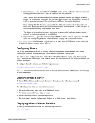
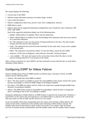
![Configuring ESRP for Hitless Failover
the continued presence of the master. All unicast flows are preserved, and the ports retain the same
state throughout the failover.
To configure the desired operation of hitless failover when ESRP is in use, use the following command:
configure msm-failover esrp-failover-mode [none | rapid-reelection |
remain-esrp-master-in-l2-domains {<reelect-timeout>}]
where the following is true:
• none—Specifies that ESRP does not participate in hitless failover. The master switch blocks its ports
during a failover and performs a full initialization of ESRP. This is the default.
• rapid-reelection—Specifies that ESRP behaves as if none was selected. In addition, if a failover
occurs when the switch is the master in an ESRP domain, the switch sends a notification that the
standby nodes should elect a new master as soon as possible. This facilitates a faster ESRP master
reelection than none.
• remain-esrp-master-in-l2-domains—Specifies that an ESRP master notifies the standby nodes of
the failover and wishes to remain the master. Along with the notification, it sends the amount of
time in seconds that the standby nodes should wait before beginning reelection.
— reelect-timeout—Specifies the amount of time the standby nodes should wait before beginning
reelection. The default is 30 seconds, and the range is 15 - 180 seconds.
When the master finishes initializing, it resumes communication with the standby nodes, and the
standby nodes revert to their standard timeout value.
ESRP Domain Behavior
The configure msm-failover esrp-failover-mode command affects all ESRP domains. However,
individual domains may respond differently to hitless failover depending on circumstances and
configurations.
When using the remain-esrp-master-in-l2-domains option, the behavior is hitless within an ESRP
domain whenever that domain is configured with layer 2 tracking options only. If you have an ESRP
domain with layer 3 tracking options, or you configure an ESRP VLAN to have both layer 2 and layer 3
tracking options, the remain-esrp-master-in-l2-domains option is overridden. Rather, the ESRP
domain or VLAN assumes the behavior of the rapid-reelection option.
Table 13: Hitless failover support for ESRP tracking options
Tracking Option Hitless Support
Diagnostic Yes
Environment Yes
VLAN Yes
OSPF, BGP, RIP No
IP Route No
Ping No
For more information about ESRP and ESRP tracking, see the chapter “Extreme Standby Routing
Protocol” in the ExtremeWare Software User Guide.
Hitless Failover and Hitless Upgrade 107](https://image.slidesharecdn.com/extremewareuserguide72-110124002726-phpapp01/85/Extreme-wareuserguide72-107-320.jpg)
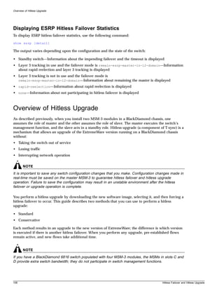
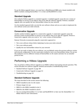
![Performing a Hitless Upgrade
• You configured the system for hitless failover operation (see “Configuring Hitless Failover” on
page 103 for more information)
NOTE
If you have an active Telnet session and initiate a hitless failover on that switch, the session disconnects
when failover occurs.
To failover to the same, new software image, do the following:
1 Download the new software image to the primary image space using the following command:
download image [<hostname> | <ip address>] <filename>
where the following is true:
• hostname—Specifies the hostname of the TFTP server from which the image should be obtained
(DNS must be enabled to use this option)
• ip address—Specifies the IP address of the TFTP server from which the image should be
obtained
• filename—Specifies the filename of the new software image
The primary image loads on both the master and slave MSM.
2 To use the new software image on the slave, you must reboot the slave before the failover can take
place.
Reboot MSM-B using the following command:
reboot slot msm-b
where msm-b specifies the slave MSM-3 installed in slot B.
After you reboot the slave, the new software image begins running on the slave.
The master downloads it’s configurations, FDB entries, etc. to the slave. After the master finishes it’s
download, the following message is logged:
Slave MSM initialized for hitless failover operation.
3 Verify that the correct BootROM and ExtremeWare version are loaded using the show switch and
show version commands.
4 Initiate failover using the following command:
run msm-failover
MSM-B becomes the master and runs the new software image. MSM-A becomes the slave and also
runs the new software image.
5 Verify the slave state using the following command:
show msm-failover
You can also verify the slave state by viewing the syslog. To view the syslog, use the following
command:
show log
110 Hitless Failover and Hitless Upgrade](https://image.slidesharecdn.com/extremewareuserguide72-110124002726-phpapp01/85/Extreme-wareuserguide72-110-320.jpg)
![Performing a Hitless Upgrade
Conservative Software Upgrade
The steps described in this section assume the following:
• MSM-3 installed in slot A is the master
• Primary image is in use
• MSM-A is the MSM-3 installed in slot A
• MSM-B is the MSM-3 installed in slot B
• You are running ExtremeWare 7.1.1 or later and BootROM 8.1 or later (see the ExtremeWare 7.1.1
Release Notes for more information)
• You configured the system for hitless failover operation (see “Configuring Hitless Failover” on
page 103 for more information)
NOTE
If you have an active Telnet session and initiate a hitless failover on that switch, the session disconnects
when failover occurs.
To failback to the previous software image, do the following:
1 Choose the secondary image of MSM-A using the following command:
use image secondary
2 Download the new software image to the secondary image space using the following command:
download image [<hostname> | <ip address>] <filename>
where the following is true:
• hostname—Specifies the hostname of the TFTP server from which the image should be obtained
(DNS must be enabled to use this option)
• ip address—Specifies the IP address of the TFTP server from which the image should be
obtained
• filename—Specifies the filename of the new software image
3 Verify that the correct BootROM and ExtremeWare version are loaded using the show switch and
show version commands.
4 Force the slave to boot up using the new software version. This must happen before failover can
occur.
Reboot MSM-B using the following command:
reboot slot msm-b
where msm-b specifies the slave MSM-3 installed in slot B.
After the slave is reset, a series of log messages are displayed:
• The first message indicates that MSM-B has initialized as a slave
• Another message appears for each database download (configurations, FDB entries, etc.)
• When all of the databases are downloaded, a message indicates that the slave is fully prepared
for execution of a failover
5 Select the primary image (that now contains the older software release) using the following
command:
use image primary
Hitless Failover and Hitless Upgrade 111](https://image.slidesharecdn.com/extremewareuserguide72-110124002726-phpapp01/85/Extreme-wareuserguide72-111-320.jpg)
![Performing a Hitless Upgrade
6 Initiate failover using the following command:
run msm-failover
The failover allows MSM-B to become the master running the new software release. Because the
current image selected is primary, MSM-A reboots to the old release. MSM-B then downloads the
original configuration from MSM-A back to MSM-A.
NOTE
If you issue any configuration command (configuration, enable, disable, create, etc.) after a conservative
upgrade, you are unable to downgrade to the previous software release.
By using the conservative method, you can upgrade or downgrade software without disrupting the
network. This method allows you to test new software releases because you:
• Will not disrupt the network
• Can failback to your previous software version and configurations saved to MSM-A
If you want to failback to MSM-A after you test a software release, enter the run msm-failover
command. MSM-A becomes the master and runs the software and configurations you had in place
before the upgrade.
After you qualify the new software release and determine that you do not want to failback to the
previous software release, enter the use image secondary command. The next time you reboot the
switch, both MSM-3s run the new software image.
Troubleshooting
If you encounter problems during a hitless upgrade, this section may be helpful. If you have a problem
not listed here or in the release notes, contact your Extreme Networks Technical Support representative.
MSM-3 Initialization
If the slave MSM-3 does not initialize properly, you can restart the MSM hardware, including the switch
fabric, using the following command:
reboot slot [msm-a | msm-b] hard-reset
where the following is true:
• msm-a—Specifies the slave MSM-3 module installed in slot A.
• msm-b—Specifies the slave MSM-3 module installed in slot B.
• hard-reset—Restarts the MSM hardware, processor, and switch fabric. If you select this option, you
will experience some traffic loss.
NOTE
If you enter the hard-reset option, a hitless upgrade does not occur.
After you enter the hard-reset option, a warning message is displayed that indicates some of the
switch forwarding operations may be briefly interrupted, and you are asked to confirm the operation. If
you do not want to interrupt switch forwarding, do not confirm the operation.
112 Hitless Failover and Hitless Upgrade](https://image.slidesharecdn.com/extremewareuserguide72-110124002726-phpapp01/85/Extreme-wareuserguide72-112-320.jpg)
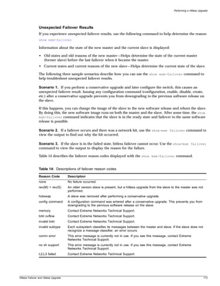

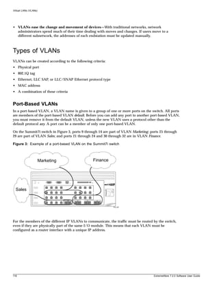
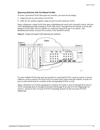
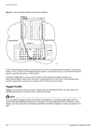
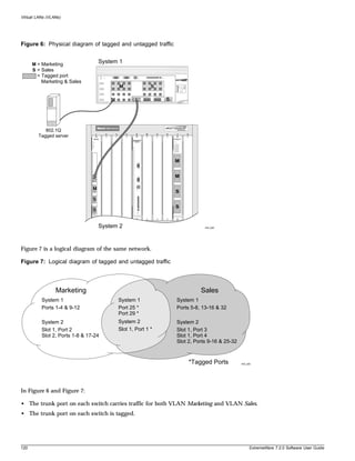
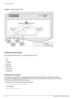
![Types of VLANs
The protocol name can have a maximum of 32 characters.
2 Configure the protocol using the following command:
configure protocol <protocol_name> add <protocol_type> <hex_value>
{<protocol_type> <hex_value>} ...
Supported protocol types include:
— etype—EtherType.
The values for etype are four-digit hexadecimal numbers taken from a list maintained by the
IEEE. This list can be found at the following URL:
http://standards.ieee.org/regauth/ethertype/index.html
— llc—LLC Service Advertising Protocol (SAP).
The values for llc are four-digit hexadecimal numbers that are created by concatenating a
two-digit LLC Destination SAP (DSAP) and a two-digit LLC Source SAP (SSAP).
— snap—Ethertype inside an IEEE SNAP packet encapsulation.
The values for snap are the same as the values for etype, described previously.
For example:
configure protocol fred add llc feff
configure protocol fred add snap 9999
A maximum of 15 protocol filters, each containing a maximum of six protocols, can be defined. On
products that use the Inferno chip set, all 15 protocol filters can be active and configured for use. On all
other platforms, no more than seven protocols can be active and configured for use.
NOTE
For more information on SNAP for Ethernet protocol types, see TR 11802-5:1997 (ISO/IEC) [ANSI/IEEE
std. 802.1H, 1997 Edition].
Deleting a Protocol Filter
If a protocol filter is deleted from a VLAN, the VLAN is assigned a protocol filter of none. You can
continue to configure the VLAN. However, no traffic is forwarded to the VLAN until a protocol is
assigned to it.
Precedence of Tagged Packets Over Protocol Filters
If a VLAN is configured to accept tagged packets on a particular port, incoming packets that match the
tag configuration take precedence over any protocol filters associated with the VLAN.
ExtremeWare 7.2.0 Software User Guide 123](https://image.slidesharecdn.com/extremewareuserguide72-110124002726-phpapp01/85/Extreme-wareuserguide72-123-320.jpg)
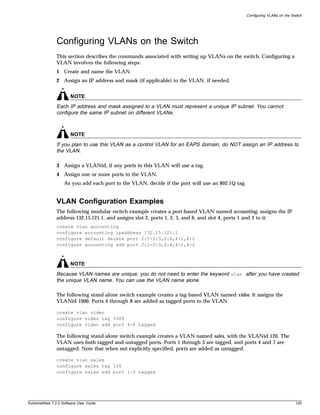
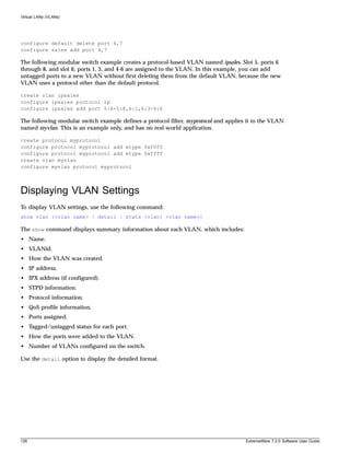
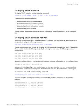
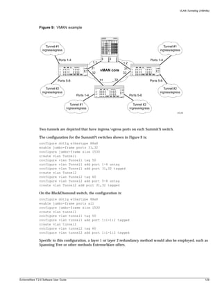
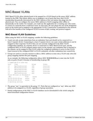
![MAC-Based VLANs
MAC-Based VLAN Limitations
The following list contains the limitations of MAC-based VLANs:
• Ports participating in MAC VLANs must first be removed from any static VLANs.
• The MAC- to-VLAN mapping can only be associated with VLANs that exist on the switch.
• A MAC address cannot be configured to associate with more than 1 VLAN. If this is attempted, the
MAC address is associated with the most recent VLAN entry in the MAC-to-VLAN database.
• The feature is intended to support one client per physical port. Once a client MAC address has
successfully registered, the VLAN association remains until the port connection is dropped or the
FDB entry ages out.
MAC-Based VLAN Example
In this following example, three VLANs are created: engineering, marketing, and sales. A single MAC
address is associated with each VLAN. The MAC address 00:00:00:00:00:02 has a group number of
“any” or “0” associated with it, allowing it to be plugged into any port that is in MacVlanDiscover
mode (ports 10-15 in this case). The MAC address 00:00:00:00:00:01 has a group number of 10 associated
with it, and can only be assigned to a VLAN if inserted into ports 16 or 17. The MAC address
00:00:00:00:00:03 has a group number of 200 associated with it and can only be inserted into ports 18
through 20.
enable mac-vlan mac-group any ports 10-15
enable mac-vlan mac-group 10 ports 16-17
enable mac-vlan mac-group 200 ports 18-20
configure mac-vlan add mac-address 00:00:00:00:00:01 mac-group 10 engineering
configure mac-vlan add mac-address 00:00:00:00:00:02 mac-group any marketing
configure mac-vlan add mac-address 00:00:00:00:00:03 mac-group 200 sales
Timed Configuration Download for MAC-Based VLANs
To allow centralized control of MAC-based VLANs over multiple switches, a timed TFTP configuration
download allows you to download incremental configuration files from a primary or secondary server
at specified time intervals. The timed downloads are configurable in 24 hour intervals. When a switch
reboots, the configuration is automatically downloaded immediately after booting, per the configured
primary and secondary servers.
To configure the primary and/or secondary server and file name, use the following command:
configure download server [primary | secondary] [<ip address> | <hostname>] <filename>
ExtremeWare 7.2.0 Software User Guide 131](https://image.slidesharecdn.com/extremewareuserguide72-110124002726-phpapp01/85/Extreme-wareuserguide72-131-320.jpg)
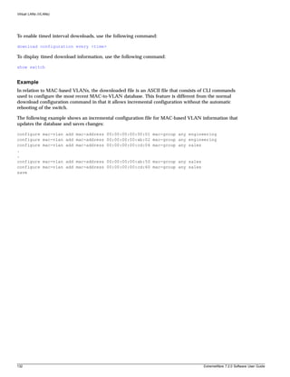
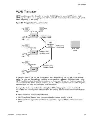
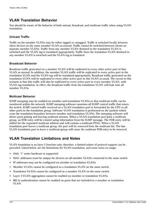
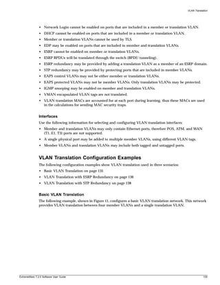
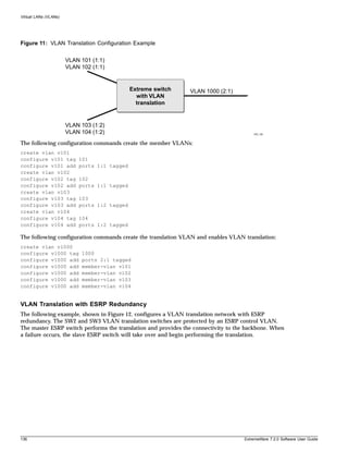
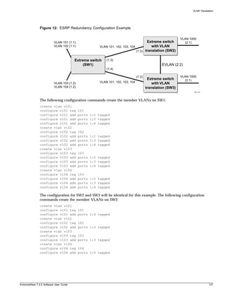
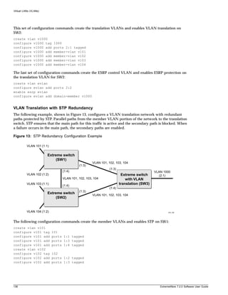
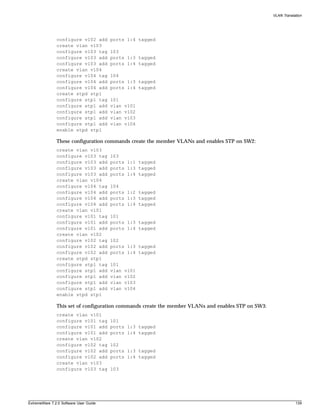
![Forwarding Database (FDB)
Associating QoS Profiles with an FDB Entry
You can associate QoS profiles with a MAC address (and VLAN) of a device by creating a permanent
FDB entry and specifying QoS profiles for ingress or egress, or both. The permanent FDB entry can be
either dynamic (it is learned and can be aged out) or static.
To associate a QoS profile with a dynamic FDB entry, use the following command:
create fdbentry [<mac_address> | broadcast-mac | any-mac] vlan <vlan name> dynamic
[qosprofile <qosprofile> {ingress-qosprofile <inqosprofile>} | ingress-qosprofile
<inqosprofile> {qosprofile <qosprofile>}]]
This command associates QoS profiles with packets received from or destined for the specified MAC
address, while still allowing the FDB entry to be dynamically learned. If you specify only the ingress
QoS profile, the egress QoS profile defaults to none, and vice-versa. If both profiles are specified, the
source MAC address of an ingress packet and the destination MAC address of an egress packet are
examined for QoS profile assignment.
The FDB entry is not actually created until the MAC address is encountered as the source MAC address
in a packet. Thus, initially the entry may not appear in the show fdb output. Once the entry has been
learned, it is created as a permanent dynamic entry, designated by “dpm” in the flags field of the show
fdb output.
You can display permanent FDB entries, including their QoS profile associations by using the
permanent option in the following command:
show fdb {<mac_address> | broadcast-mac | permanent | ports <portlist> | remap | vlan
<vlan name>}
To associate a QoS profile with a permanent FDB entry, use the following command:
create fdbentry <mac_address> vlan <vlan name> ports [<portlist> | all] {qosprofile
<qosprofile>} {ingress-qosprofile <inqosprofile>}
This entry will not be aged out, and no learning will occur. If the same MAC address is encountered
through a virtual port not specified in the portlist, it will be handled as a blackhole entry.
Using the any-mac keyword, you can enable traffic from a QoS VLAN to have higher priority than
802.1p traffic. Normally, an 802.1p packet has a higher priority over the VLAN classification. In order to
use this feature, you must create a wildcard permanent FDB entry named any-mac and apply the QoS
profile to the individual MAC entry.
NOTE
For more information on QoS profiles, see Chapter 8.
Scanning the FDB
You can scan the FDB on a stand-alone switch or on a slot or backplane basis on a modular switch. This
setting is independent of and in addition to the system health check configuration, and the following
commands do not affect the system health check configurations.
144 ExtremeWare 7.2.0 Software User Guide](https://image.slidesharecdn.com/extremewareuserguide72-110124002726-phpapp01/85/Extreme-wareuserguide72-144-320.jpg)
![Scanning the FDB
For more information about the system health checker and configuring the system health checker, see
Chapter 11.
Enabling FDB Scanning
By default, FDB scanning is disabled. To enable FDB scanning on a stand-alone switch, use the
following command:
enable fdb-scan
To enable FDB scanning on an Alpine switch, use the following command:
enable fdb-scan [all | slot {{backplane} | <slot number> | msm-a | msm-b}]
To enable FDB scanning on a BlackDiamond switch, use the following command:
enable fdb-scan [all | slot {{backplane} | <slot number> | msm-a | msm-b}]
where the following is true:
• all—Specifies all of the slots in the chassis. This is available on modular switches only.
• backplane—Specifies the backplane of the Alpine chassis. This is available on Alpine switches only.
• slot number—Specifies the slot number of the module to scan. This is available on BlackDiamond
switches only.
• msm-a—Specifies the MSM installed in slot A. This is available on BlackDiamond switches only.
• msm-b—Specifies the MSM installed in slot B. This is available on BlackDiamond switches only.
Disabling FDB Scanning
To disable FDB scanning on a stand-alone switch, use the following command:
disable fdb-scan
To disable FDB scanning on an Alpine switch, use the following command:
disable fdb-scan [all | slot {{backplane} | <slot number> | msm-a | msm-b}]
To disable FDB scanning on a BlackDiamond switch, use the following command:
disable fdb-scan [all | slot {{backplane} | <slot number> | msm-a | msm-b}]
If you disable FDB scanning for a slot and the system health check is enabled, the slot is still scanned by
the system health checker.
Configuring the FDB Scan Interval
You can configure the amount of time between FDB scans. To set the interval between FDB scans, use
the following command:
configure fdb-scan period <period <1-60>>
The default is 30 seconds. The range is 1 - 60 seconds. If you configure a timer interval of less than 15
seconds, the following warning message is displayed and you are asked to confirm the change:
Setting period below (15) may starve other tasks.
ExtremeWare 7.2.0 Software User Guide 145](https://image.slidesharecdn.com/extremewareuserguide72-110124002726-phpapp01/85/Extreme-wareuserguide72-145-320.jpg)
![Forwarding Database (FDB)
Do you wish to do this? (yes, no, cancel) 06/19/2003 10:29.28 <INFO:SYST> serial
admin: configure fdb-scan period 1
n
NOTE
Extreme Networks recommends an interval period of at least 15 seconds.
To return the FDB scan interval to the factory default of 30 seconds, use the following command:
unconfigure fdb-scan period
If the switch detects too many failures within the specified scan period, the messages are either sent to
the syslog or the configured system health check action is taken.
To configure the action the switch takes when too many failures are detected, use the following
command:
configure fdb-scan failure-action [log | sys-health-check]
where the following is true:
• log—Messages are sent to the syslog. Only one instance of an error messages is logged at this level.
This is the default configuration.
• sys-health-check—The configured system health check action is taken.
To return the switch to the factory default of sending messages to the syslog, use the following
command:
unconfigure fdb-scan failure-action
Displaying FDB Scan Statistics
To display the FDB scan statistics, use the following command:
show diagnostics sys-health-check
The following is an example of the type of FDB scan statistics output displayed:
FDB Scan results:
CardState NumFail NumScan Entry LastFailTime
BPLNE : Operational 0 64
FDB Configuration Examples
The following example adds a permanent static entry to the FDB:
create fdbentry 00:E0:2B:12:34:56 vlan marketing port 3:4
The permanent entry has the following characteristics:
• MAC address is 00:E0:2B:12:34:56.
• VLAN name is marketing.
• Slot number for this device is 3.
146 ExtremeWare 7.2.0 Software User Guide](https://image.slidesharecdn.com/extremewareuserguide72-110124002726-phpapp01/85/Extreme-wareuserguide72-146-320.jpg)
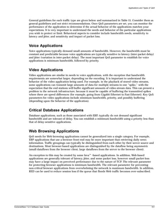
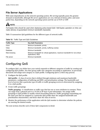
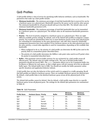
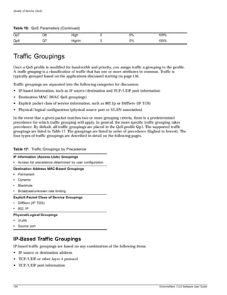
![Traffic Groupings
IP-based traffic groupings are defined using access lists. Access lists are discussed in detail in
Chapter 12. By supplying a named QoS profile at the end of the access list command syntax, you can
prescribe the bandwidth management and priority handling for that traffic grouping. This level of
packet filtering has no impact on performance.
MAC-Based Traffic Groupings
QoS profiles can be assigned to destination MAC addresses. MAC-based traffic groupings are
configured using the create fdb... command:
The MAC address options, defined below, are as follows:
• Permanent
• Dynamic
• Blackhole
• Broadcast/unknown rate limiting
Permanent MAC addresses
Permanent MAC addresses can be assigned a QoS profile whenever traffic is destined to the MAC
address. This can be done when you create a permanent FDB entry using the following command:
create fdbentry <mac_address> vlan <vlan name> ports [<portlist> | all] {qosprofile
<qosprofile>} {ingress-qosprofile <inqosprofile>}
For example:
create fdbentry 00:11:22:33:44:55 vlan default port 4:1 qosprofile qp2
Dynamic MAC Addresses
Dynamic MAC addresses can be assigned a QoS profile whenever traffic is destined to the MAC
address. This is done using the following command:
create fdbentry [<mac_address> | broadcast-mac | any-mac] vlan <vlan name> dynamic
[qosprofile <qosprofile> {ingress-qosprofile <inqosprofile>} | ingress-qosprofile
<inqosprofile> {qosprofile <qosprofile>}]
For any port on which the specified MAC address is learned in the specified VLAN, the port is assigned
the specified QoS profile. For example:
create fdbentry 00:11:22:33:44:55 vlan default dynamic qosprofile qp3
The QoS profile is assigned when the MAC address is learned. If a client's location moves, the assigned
QoS profile moves with the device. If the MAC address entry already exists in the FDB, you can clear
the forwarding database so that the QoS profile can be applied when the entry is added again. Use the
following command to clear the FDB:
clear fdb
Blackhole MAC Address
Using the blackhole option configures the switch to not forward any packets to the destination MAC
address on any ports for the VLAN specified. The blackhole option is configured using the following
command:
ExtremeWare 7.2.0 Software User Guide 155](https://image.slidesharecdn.com/extremewareuserguide72-110124002726-phpapp01/85/Extreme-wareuserguide72-155-320.jpg)
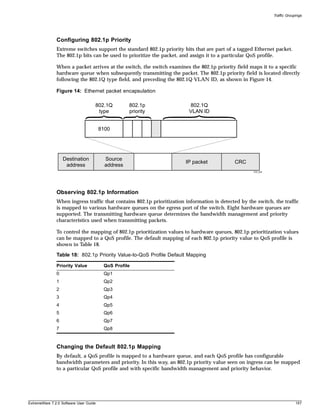
![Quality of Service (QoS)
To change the default mappings of QoS profiles to 802.1p priority values, use the following command:
configure dot1p type <dot1p_priority> qosprofile <qosprofile>
Configuring 802.1p Priority For Slow Path Traffic
Some traffic can originate on the switch, for example Ping or Telnet packets. This traffic comes from the
switch CPU and is referred to as slow path traffic. This traffic is internally tagged with an 802.1p
priority of 7, by default, and egresses the VLAN through the highest queue. If you want to set a
different tag (and priority) use the following command to set the priority to a number between 0 and 7:
configure vlan <vlan name> priority <priority>
Other traffic transported across the switch and VLAN will not be changed, in other words, the 802.1p
values will not be affected by the VLAN priority setting.
Replacing 802.1p Priority Information
By default, 802.1p priority information is not replaced or manipulated, and the information observed on
ingress is preserved when transmitting the packet. This behavior is not affected by the switching or
routing configuration of the switch.
However, the switch is capable of inserting and/or overwriting 802.1p priority information when it
transmits an 802.1Q tagged frame. If 802.1p replacement is enabled, the 802.1p priority information that
is transmitted is determined by the hardware queue that is used when transmitting the packet. To
replace 802.1p priority information, use the following command:
enable dot1p replacement ports [<portlist> | all]
802.1p priority information is replaced according to the hardware queue that is used when transmitting
from the switch. The mapping is described in Table 19. This mapping cannot be changed.
Table 19: Queue to 802.1p Priority Replacement Value
Hardware Queue 802.1p Priority
Replacement Value
Q0 0
Q1 1
Q2 2
Q3 3
Q4 4
Q5 5
Q6 6
Q7 7
Configuring DiffServ
Contained in the header of every IP packet is a field for IP Type of Service (TOS), now also called the
DiffServ field. The TOS field is used by the switch to determine the type of service provided to the
packet.
Observing DiffServ code points as a traffic grouping mechanism for defining QoS policies and
overwriting the Diffserv code point fields are supported.
158 ExtremeWare 7.2.0 Software User Guide](https://image.slidesharecdn.com/extremewareuserguide72-110124002726-phpapp01/85/Extreme-wareuserguide72-158-320.jpg)
![Traffic Groupings
Figure 15 shows the encapsulation of an IP packet header.
Figure 15: IP packet header encapsulation
0 1 2 3 4 5 6 7
DiffServ code point
0 bits 31
Version IHL Type-of-service Total length
Identification Flags Fragment offset
Time-to-live Protocol Header checksum
Source address
Destination address
Options (+ padding)
Data (variable)
EW_023
Observing DiffServ Information
When a packet arrives at the switch on an ingress port, the switch examines the first six of eight TOS
bits, called the code point. The switch can assign the QoS profile used to subsequently transmit the
packet based on the code point. The QoS profile controls a hardware queue used when transmitting the
packet out of the switch, and determines the forwarding characteristics of a particular code point.
Viewing DiffServ information can be enabled or disabled; by default it is disabled. To view DiffServ
information, use the following command:
enable diffserv examination ports [<portlist> | all]
Changing DiffServ Code point assignments in the Q0S Profile
Because the code point uses six bits, it has 64 possible values (26 = 64). Be default, the values are
grouped and assigned to the default QoS profiles listed in Table 20.
Table 20: Default Code Point-to-QoS Profile Mapping
Code Point QoS Profile
0-7 Qp1
8-15 Qp2
16-23 Qp3
24-31 Qp4
32-39 Qp5
40-47 Qp6
48-55 Qp7
ExtremeWare 7.2.0 Software User Guide 159](https://image.slidesharecdn.com/extremewareuserguide72-110124002726-phpapp01/85/Extreme-wareuserguide72-159-320.jpg)
![Quality of Service (QoS)
Table 20: Default Code Point-to-QoS Profile Mapping (Continued)
Code Point QoS Profile
56-63 Qp8
You can change the QoS profile assignment for all 64 code points using the following command:
configure diffserv examination code-point <code_point> qosprofile <qosprofile> ports
[<portlist> | all] {low-drop-probability | high-drop-probability}
Once assigned, the rest of the switches in the network prioritize the packet using the characteristics
specified by the QoS profile.
Replacing DiffServ Code Points
The switch can be configured to change the DiffServ code point in the packet prior to the packet being
transmitted by the switch. This is done with no impact on switch performance.
The DiffServ code point value used in overwriting a packet is determined by the 802.1p priority value.
The 802.1p priority value is, in turn, determined by the hardware queue used when transmitting a
packet, as described in “Replacing 802.1p Priority Information” on page 158.
It is not necessary to receive or transmit 802.1Q tagged frames, only to understand that the egress
hardware queue, which also determines the 802.1p priority value, can also be configured to determine
the DiffServ code point value if you want to replace the DiffServ code points.
To replace DiffServ code points you must enable both 802.1p replacement and DiffServ replacement
using the following commands:
enable dot1p replacement ports [<portlist> | all]
enable diffserv replacement ports [<portlist> | all]
The default 802.1p priority value to code point mapping is described in Table 21.
Table 21: Default 802.1p Priority Value-to-Code Point Mapping
802.1p Priority
Hardware Queue value Code Point
Q0 0 0
Q1 1 8
Q2 2 16
Q3 3 24
Q4 4 32
Q5 5 40
Q6 6 48
Q7 7 56
You then change the 802.1p priority to DiffServ code point mapping to any code point value using the
following command:
configure diffserv replacement priority <value> code-point <code_point> ports
[<portlist> | all]
160 ExtremeWare 7.2.0 Software User Guide](https://image.slidesharecdn.com/extremewareuserguide72-110124002726-phpapp01/85/Extreme-wareuserguide72-160-320.jpg)
![Traffic Groupings
By doing so, the hardware queue used to transmit a packet determines the DiffServ value replaced in
the IP packet.
To verify the DiffServ configuration, use the following command:
show ports {mgmt | <portlist>} [t1 | e1 | t3] info
DiffServ Example
In this example, we use DiffServ to signal a class of service throughput and assign any traffic coming
from network 10.1.2.x with a specific DiffServ code point. This allows all other network switches to send
and observe the Diffserv code point instead of repeating the same QoS configuration on every network
switch.
To configure the switch that handles incoming traffic from network 10.1.2.x, follow these steps:
1 Configure parameters of the QoS profile QP3:
configure qp3 min 10 max 100
2 Assign a traffic grouping for traffic from network 10.1.2.x to qp3:
create access-list TenOneTwo
configure TenOneTwo 10.1.2.0/24 permit qp3
3 To enable the switch to overwrite the DiffServ code point:
enable dot1p replacement
enable diffserv replacement
4 Configure the switch so that other switches can signal class of service that this switch should
observe:
enable diffserv examination
Table 16 indicates that qp3 is tied to hardware queue Q2. We also know that when replacement is
enabled all traffic sent out Q2 will contain code point value 16 (according to Table 21). If this is the
desired code point to use, all traffic from 10.1.2.x will be sent out QP3 (at 10% minimum and 100%
maximum) with a code point value of 16.
Physical and Logical Groupings
Two traffic groupings exist in this category:
• Source port
• VLAN
Source port
A source port traffic grouping implies that any traffic sourced from this physical port uses the indicated
QoS profile when the traffic is transmitted out to any other port. To configure a source port traffic
grouping, use the following command:
configure ports <portlist> qosprofile <qosprofile>
In the following modular switch example, all traffic sourced from slot 5 port 7 uses the QoS profile
named qp3 when being transmitted.
configure ports 5:7 qosprofile qp3
ExtremeWare 7.2.0 Software User Guide 161](https://image.slidesharecdn.com/extremewareuserguide72-110124002726-phpapp01/85/Extreme-wareuserguide72-161-320.jpg)
![Quality of Service (QoS)
VLAN
A VLAN traffic grouping indicates that all intra-VLAN switched traffic and all routed traffic sourced
from the named VLAN uses the indicated QoS profile. To configure a VLAN traffic grouping, use the
following command:
configure vlan <vlan name> qosprofile <qosprofile>
For example, all devices on VLAN servnet require use of the QoS profile qp4. The command to configure
this example is as follows:
configure vlan servnet qosprofile qp4
Verifying Physical and Logical Groupings
To verify settings on ports or VLANs, use the following command:
show qosprofile
The same information is also available for ports or VLANs using one of the following commands:
show ports {mgmt | <portlist>} [t1 | e1 | t3] info
or
show vlan
Configuring QoS Traffic Grouping Priorities
Normally, there is a predetermined precedence for which traffic grouping applies to a given packet that
matches two or more grouping criteria. In general, the more specific traffic grouping takes precedence.
However, you can configure a new set of priorities using the following command:
configure qostype priority [source-mac | dest-mac | access-list | vlan | diffserv |
dot1p] <priority>
The valid priority values are 0 - 15. The default values are shown in Table 22.
Table 22: Traffic Grouping Priority Default Values
QoS Type Default Value
source-mac 7
dest-mac 8
access-list 11
vlan 1
diffserv 3
dot1p 2
QoS types with a greater value take higher precedence. For example, to force FDB source-mac QoS to
take a higher precedence over FDB dest-mac QoS, use the commands:
configure qostype priority source-mac 9
where 9 is greater than the default value assigned to the dest-mac QoS type.
162 ExtremeWare 7.2.0 Software User Guide](https://image.slidesharecdn.com/extremewareuserguide72-110124002726-phpapp01/85/Extreme-wareuserguide72-162-320.jpg)

![Modifying a QoS Configuration
Displaying QoS Profile Information
The QoS monitor can also be used to verify the QoS configuration and monitor the use of the QoS
policies that are in place. To display QoS information on the switch, use the following command:
show qosprofile {<qosprofile>} {port <portlist>}
Displayed information includes:
• QoS profile name
• Minimum bandwidth
• Maximum bandwidth
• Priority
• A list of all traffic groups to which the QoS profile is applied
Additionally, QoS information can be displayed from the traffic grouping perspective by using one or
more of the following commands:
• show fdb permanent—Displays destination MAC entries and their QoS profiles.
• show switch—Displays information including PACE enable/disable information.
• show vlan—Displays the QoS profile assignments to the VLAN.
• show ports {mgmt | <portlist>} [t1 | e1 | t3] info—Displays information including QoS
information for the port.
Modifying a QoS Configuration
If you make a change to the parameters of a QoS profile after implementing your configuration, the
timing of the configuration change depends on the traffic grouping involved. The following rules apply:
• For destination MAC-based grouping (other than permanent), clear the MAC FDB using the
command clear fdb. This command should also be issued after a configuration is implemented, as
the configuration must be in place before an entry is made in the MAC FDB. For permanent
destination MAC-based grouping, re-apply the QoS profile to the static FDB entry, as documented.
You can also save and reboot the switch.
• For physical and logical groupings of a source port or VLAN, re-apply the QoS profile to the source
port or VLAN, as documented. You can also save and reboot the switch.
Bi-Directional Rate Shaping
Bi-directional rate shaping allows you to manage bandwidth on layer 2 and layer 3 traffic flowing both
to and from the switch. You can configure up to eight ingress queues per VLAN and up to eight egress
queues per physical port. By defining minimum and maximum bandwidth for each queue, you define
committed information rates for each queue. You can define different rates for ingress and egress
queues.
You can then provide traffic groupings (such as physical port, VLAN, .1P, DiffServ, IP address, or layer 4
flow) for the predefined QoS Profiles, thereby directing specific types of traffic to the desired queue.
ExtremeWare 7.2.0 Software User Guide 165](https://image.slidesharecdn.com/extremewareuserguide72-110124002726-phpapp01/85/Extreme-wareuserguide72-165-320.jpg)
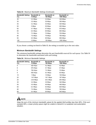
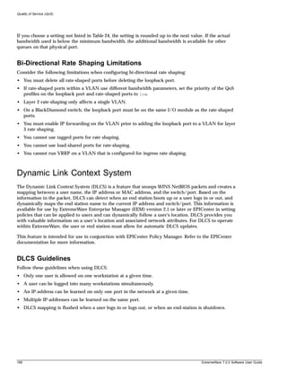
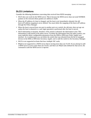

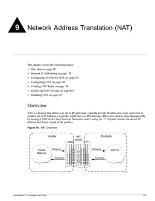
![Network Address Translation (NAT)
You can configure NAT to conserve IP address space by mapping a large number of inside (private)
addresses to a much smaller number of outside (public) addresses.
In implementing NAT, you must configure at least two separate VLANs involved. One VLAN is
configured as inside, and corresponds to the private IP addresses you would like to translate into other
IP addresses. The other type of VLAN is configured as outside, which corresponds to the public
(probably Internet) IP addresses you want the inside addresses translated to. The mappings between
inside and outside IP addresses are done via rules that specify the IP subnets involved and the
algorithms used to translate the addresses.
NOTE
The NAT modes in ExtremeWare support translating traffic that initiates only from inside addresses.
NAT rules are associated with a single outside VLAN. Multiple rules per outside VLAN are allowed.
The rules take effect in the order they are displayed using the show nat command. Any number of
inside VLANs can use a single outside VLAN, assuming that you have created proper rules. Similarly, a
single inside VLAN can use any number of different outside VLANs, assuming that the rules and
routing are set up properly.
Both TCP and UDP have layer 4 port numbers ranging from 1 to 65535. These layer 4 ports, in
combination with the IP addresses, form a unique identifier which allows hosts (as well as the NAT
switch) to distinguish between separate conversations. NAT operates by replacing the inside IP packet’s
source IP and layer 4 port with an outside IP and layer 4 port. The NAT switch maintains a connection
table to map the return packets on the outside VLAN back into their corresponding inside sessions.
Internet IP Addressing
When implementing NAT in an Internet environment, it is strongly recommended that you use one of
the reserved private IP address ranges for your inside IP addresses. These ranges have been reserved
specifically for networks not directly attached to the Internet. Using IP addresses within these ranges
prevents addressing conflicts with public Internet sites to which you want to connect. The ranges are as
follows:
• 10.0.0.0/8—Reserved Class A private address space
• 172.16.0.0/12—Reserved Class B private address space
• 192.168.0.0/16—Reserved Class C private address space
Configuring VLANs for NAT
You must configure each VLAN participating in NAT as either an inside or outside VLAN. To configure
a VLAN as an inside or outside VLAN, use the following command:
configure nat vlan <vlan name> [inside | outside | none]
When a VLAN is configured to be inside, traffic from that VLAN is translated only if it has a matching
NAT rule. Any unmatched traffic will be routed normally and not be translated. Because all traffic runs
through the central processing unit (CPU), it cannot run at line-rate.
172 ExtremeWare 7.2.0 Software User Guide](https://image.slidesharecdn.com/extremewareuserguide72-110124002726-phpapp01/85/Extreme-wareuserguide72-172-320.jpg)
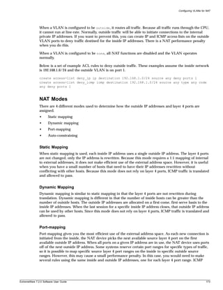
![Network Address Translation (NAT)
traffic is not translated in this mode. You must add a dynamic NAT rule for the same IP address range
to allow for ICMP traffic.
Auto-constraining
The auto-constraining algorithm for port-mapping limits the number of outside layer 4 ports a single
inside host can use simultaneously. The limitation is based on the ratio of inside to outside IP addresses.
The outside IP address and layer 4 port space is evenly distributed to all possible inside hosts. This
guarantees that no single inside host can prevent other traffic from flowing through the NAT device.
Because of the large number of simultaneous requests that can be made from a web browser, it is not
recommended that this mode be used when a large number of inside hosts are being translated to a
small number of outside IP addresses. ICMP traffic is not translated in this mode. You must add a
dynamic NAT rule for the same IP address range to allow for ICMP traffic.
Configuring NAT
The behavior of NAT is determined by the rules you create to translate the IP addresses. You must
attach each rule to a specific VLAN. All rules are processed in order. The options specified on the NAT
rule determine the algorithm used to translate the inside IP addresses to the outside IP addresses. For
outgoing (inside to outside) packets, the first rule to match is processed. All following rules are ignored.
All return packets must arrive on the same outside VLAN on which the session went out. For most
configurations, make sure that the outside IP addresses specified in the rule are part of the outside
VLAN’s subnet range, so that the switch can proxy the address resolution protocol (ARP) for those
addresses.
To enable NAT functionality, use the following command:
enable nat
Creating NAT Rules
This section describes how to configure the various types of NAT (static, dynamic, portmap, and
auto-constrain). In the examples in this section, advanced port and destination matching options have
been removed. For information on how to use some of the more advanced rule matching features, see
“Advanced Rule Matching” on page 176.
Creating Static and Dynamic NAT Rules
To create static or dynamic NAT rules, use this command:
configure nat add vlan <vlan name> map source [any | <source_ipaddress>/<mask>]
{l4-port [any | <port> {- <port>}]} {destination <dest_ipaddress>/<mask> {l4-port [any
| <port> {- <port>}]}} to <ip address> [/<mask> | - <ip address>] [tcp | udp | both]
[portmap {<min> - <max>} | auto-constrain]
This is the simplest NAT rule. You specify the outside vlan name, and a subnet of inside IP addresses,
which get translated to the outside IP address using the specified mode (static in this case). For the
outside IP addresses, you can either specify an IP address and netmask or a starting and ending IP
range to determine the IP addresses the switch will translate the inside IP addresses to. If the netmask
for both the source and NAT addresses is /32, the switch will use static NAT translation. If the netmask
for both the source and NAT addresses are not both /32, the switch will use dynamic NAT translation.
174 ExtremeWare 7.2.0 Software User Guide](https://image.slidesharecdn.com/extremewareuserguide72-110124002726-phpapp01/85/Extreme-wareuserguide72-174-320.jpg)
![Creating NAT Rules
Static NAT Rule Example
configure nat add out_vlan_1 map source 192.168.1.12/32 to 216.52.8.32/32
Dynamic NAT Rule Example
configure nat add out_vlan_1 map source 192.168.1.0/24 to 216.52.8.1 - 216.52.8.31
Creating Portmap NAT Rules
To configure portmap NAT rules, use this command:
configure nat add vlan <vlan name> map source [any | <source_ipaddress>/<mask>]
{l4-port [any | <port> {- <port>}]} {destination <dest_ipaddress>/<mask> {l4-port [any
| <port> {- <port>}]}} to <ip address> [/<mask> | - <ip address>] [tcp | udp | both]
[portmap {<min> - <max>} | auto-constrain]
The addition of an L4 protocol name and the portmap keyword tells the switch to use portmap mode.
Optionally, you may specify the range of L4 ports the switch chooses on the translated IP addresses, but
there is a performance penalty for doing this. Remember that portmap mode will only translate TCP
and/or UDP, so a dynamic NAT rule must be specified after the portmap rule in order to allow ICMP
packets through without interfering with the portmapping.
Portmap NAT Rule Example
configure nat add out_vlan_2 map source 192.168.2.0/25 to 216.52.8.32 /28 both portmap
Portmap Min-Max Example
configure nat add out_vlan_2 map source 192.168.2.128/25 to 216.52.8.64/28 tcp portmap
1024 - 8192
Creating Auto-Constrain NAT Rules
To create auto-constrain NAT rules, use the following command:
configure nat add vlan <vlan name> map source [any | <source_ipaddress>/<mask>]
{l4-port [any | <port> {- <port>}]} {destination <dest_ipaddress>/<mask> {l4-port [any
| <port> {- <port>}]}} to <ip address> [/<mask> | - <ip address>] [tcp | udp | both]
[portmap {<min> - <max>} | auto-constrain]
This rule uses auto-constrain NAT. Remember that each inside IP address will be restricted in the
number of simultaneous connections. Most installations should use portmap mode.
Auto-Constrain Example
configure nat add out_vlan_3 map source 192.168.3.0/24 to 216.52.8.64/32 both
auto-constrain
ExtremeWare 7.2.0 Software User Guide 175](https://image.slidesharecdn.com/extremewareuserguide72-110124002726-phpapp01/85/Extreme-wareuserguide72-175-320.jpg)
![Network Address Translation (NAT)
Advanced Rule Matching
By default, NAT rules only match connections based on the source IP address of the outgoing packets.
Using the L4-port and destination keywords, you can further limit the scope of the NAT rule so that
it only applied to specific TCP/UDP layer 4 port numbers, or specific outside destination IP addresses.
NOTE
Once a single rule is matched, no other rules are processed.
Destination Specific NAT
configure nat add vlan <vlan name> map source [any | <source_ipaddress>/<mask>]
{l4-port [any | <port> {- <port>}]} {destination <dest_ipaddress>/<mask> {l4-port [any
| <port> {- <port>}]}} to <ip address> [/<mask> | - <ip address>] [tcp | udp | both]
[portmap {<min> - <max>} | auto-constrain]
The addition of the destination optional keyword after the source IP address and mask allows the
NAT rule to be applied to only packets with a specific destination IP address.
L4-Port Specific NAT
The addition of the L4-port optional keyword after the source IP address and mask allows the NAT
rule to be applied to only packets with a specific L4 source or destination port. If you use the L4-port
command after the source IP/mask, the rule will only match if the port(s) specified are the source
L4-ports. If you use the L4-port command after the destination IP/mask, the rule will only match if the
port(s) specified are the destination L4-ports. Both options may be used together to further limit the
rule.
Configuring Time-outs
When an inside host initiates a session, a session table entry is created. Depending on the type of traffic
or the current TCP state, the table entries time out after the configured time-out expires.
Displaying NAT Settings
To display NAT rules, use the following command:
show nat {timeout | stats | connections | rules {vlan <outside_vlan>}}
This command displays the NAT rules for a specific VLAN. Rules are displayed in the order they are
processed, starting with the first one.
To display NAT traffic statistics, use the following command:
show nat stats
This command displays statistics for the NAT traffic, and includes:
• The number of rules
• The number of current connections
• The number of translated packets on the inside and outside VLANs
176 ExtremeWare 7.2.0 Software User Guide](https://image.slidesharecdn.com/extremewareuserguide72-110124002726-phpapp01/85/Extreme-wareuserguide72-176-320.jpg)
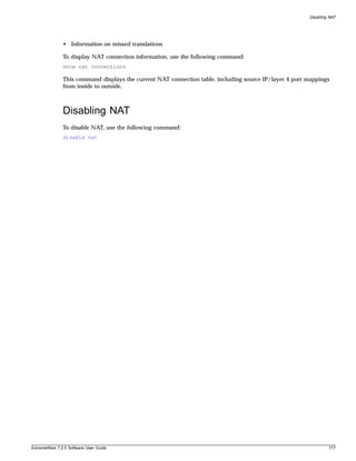

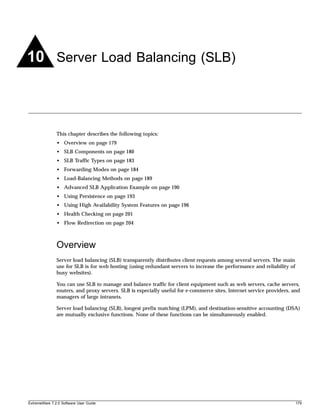
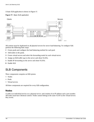
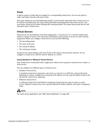
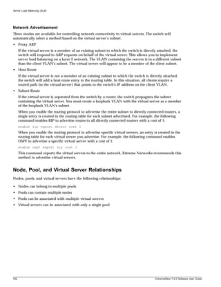
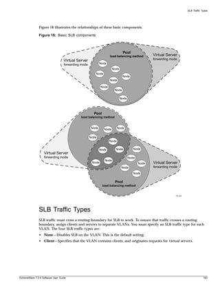
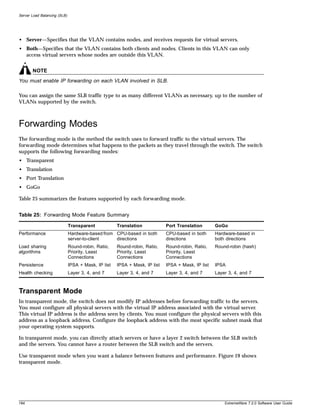
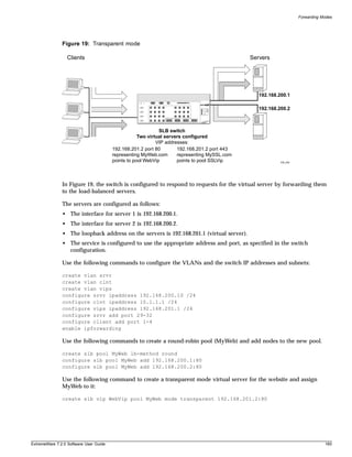
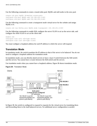
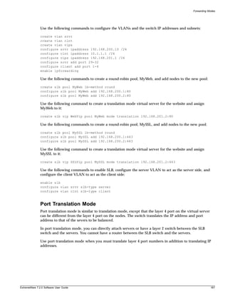
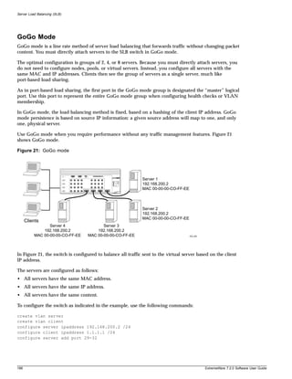
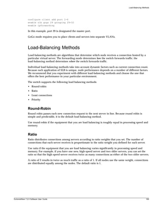
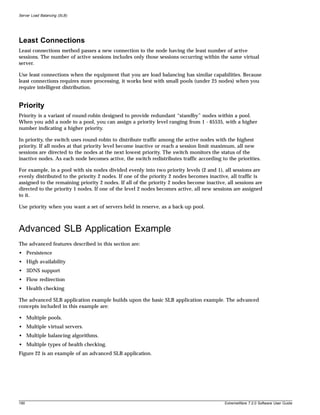
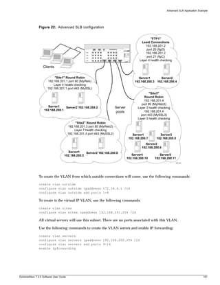
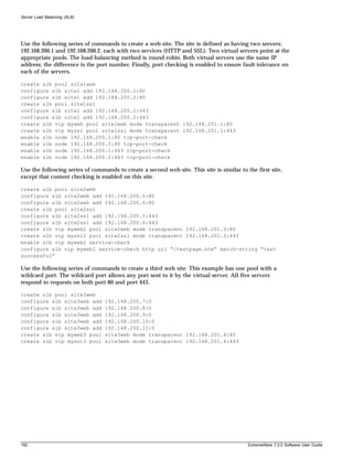
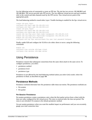
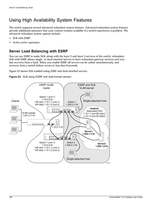
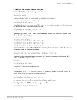
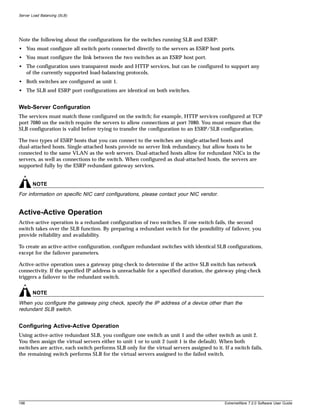
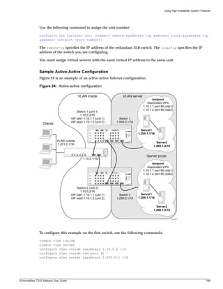
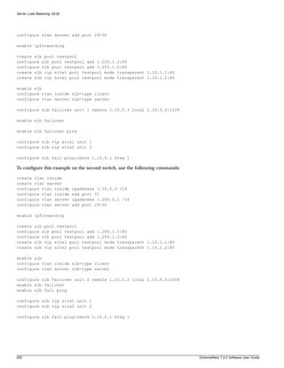
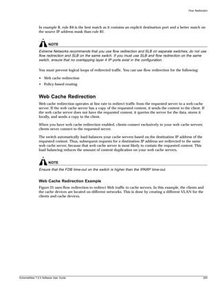
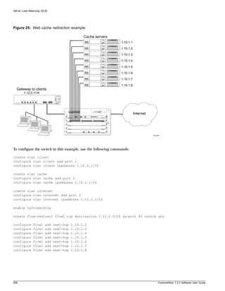
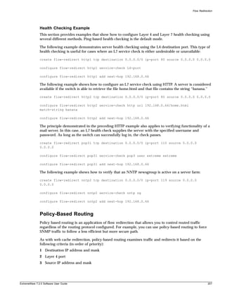
![Status Monitoring and Statistics
Slot Diagnostics
The BlackDiamond switch provides a facility for running normal or extended diagnostics on an I/O
module or a Management Switch Fabric Module (MSM) without affecting the operation of the rest of
the system.
If you select to run the diagnostic routine on an I/O module, that module is taken off-line while the
diagnostic test is performed. Traffic to and from the ports on the module are temporarily unavailable.
Once the diagnostic test is completed, the I/O module is reset and becomes operational again.
You can run normal or extended diagnostics on the slave MSM. The normal diagnostic routing is a short
series of tests that do not test all the internal Application-Specific Integrated Circuit (ASIC) functions.
The extended diagnostic routine tests coverage of all MSM components including the internal ASIC
functions. The slave MSM is taken off-line while the diagnostic test is performed. It is reset and
operational once the test is completed.
If you want the diagnostic routine to run on the master MSM every time the system boots, use the
following command:
configure diagnostics fastpost
To turn off the diagnostic routine, use the following command:
configure diagnostics off
If you want the diagnostic routine to run one time (rather than with each system boot), use the
following command:
run diagnostics [extended | normal | packet memory] slot [<slot number> | msm-a |
msm-b]
where the following is true:
• normal—Takes the switch fabric and ports offline, and performs a simple ASIC and packet loopback
test on all ports. The test is completed in 30 seconds. CPU and out-of-band management ports are
not tested in this mode. As a result, console and Telnet access from the management port is available
during this routine.
• extended—Takes the switch fabric and ports offline, and performs extensive ASIC, ASIC-memory,
and packet loopback tests. Extended diagnostic tests take a maximum of 15 minutes. The CPU is not
tested. Console access is available during extended diagnostics.
• <slot>—Specifies the slot number of an I/O module. Once the diagnostics test is complete, the
system attempts to bring the I/O module back online. This parameter is applicable to the
BlackDiamond switch, only.
• msm-a | msm-b—Specifies the slot letter of an MSM. If the master MSM is specified, the diagnostic
routine is performed when the system reboots. Both switch fabric and management ports are taken
offline during diagnostics. This parameter is applicable to the BlackDiamond switch, only.
Runtime Diagnostics (BlackDiamond Switches)
BlackDiamond switch runtime diagnostics perform a single test on a single I/O module. All error
messages are logged. To perform diagnostics on an I/O module, use the following command:
run diagnostics [extended | normal | packet memory] slot [<slot number> | msm-a |
msm-b]
210 ExtremeWare 7.2.0 Software User Guide](https://image.slidesharecdn.com/extremewareuserguide72-110124002726-phpapp01/85/Extreme-wareuserguide72-210-320.jpg)
![Slot Diagnostics
Use the normal option when you want a fast (30 – 60 seconds) hardware status check. Use the extended
option when you want a more thorough test. The extended option requires significantly more time to
complete, depending on the number of ports on the blade.
You can also execute packet memory scanning for all packet memory associated with the specified I/O
slot on a BlackDiamond 6804, 6808, or 6816 switches, using the following command:
run diagnostics packet-memory slot <slot number>
The packet memory diagnostic scans the specified blade to detect single bit-related memory defects and
their associated buffer locations. If packet memory defects are detected, their locations are recorded in
the blade’s EEPROM. Up to eight occurrences can be recorded. If a defect was found during the scan
process, the card is reset, the defective buffer is mapped out from further use, and the I/O card is
returned to the operational state. If more than eight defects are detected, or if the defects cannot be
mapped out, the card is treated as a failed card and left offline. The card should then be returned
through the RMA process with Extreme Networks Technical Support.
NOTE
Only run extended or packet-memory diagnostics when the switch can be brought off-line. The tests
conducted during these diagnostics are extensive and can affect traffic that must be processed by the
system CPU.
To view results of the normal or extended diagnostics test, use the following command:
show diagnostics
To view the results of a packet memory scan, use the following command:
show diagnostics packet-memory [slot <slot number>]
Packet Memory Scanning (BlackDiamond Switches)
You can scan and check the health of individual BlackDiamond modules rather than the overall system
by configuring packet memory scanning on a per slot basis. If you have the system health check
configured for auto-recovery, and you configure packet memory scanning on a slot, you can define that
slot’s behavior if an error is discovered. By default, packet memory scanning is disabled.
To configure packet memory scanning on a BlackDiamond module, use the following command:
configure packet-mem-scan-recovery-mode [offline | online] [msm-a | msm-b | <slot
number>]
where the following is true:
• offline—Specifies that a module is taken offline and kept offline if one of the following occurs:
— More than eight defects are detected.
— Three consecutive checksum error were detected by the health checker, but no new defects were
found by the memory scanning and mapping process.
— After defects were detected and mapped out, the same checksum errors are again detected by the
system health checker.
• online—Specifies that a faulty module is kept online, regardless of how many errors are detected.
• msm-a—Specifies the MSM module installed in slot A.
ExtremeWare 7.2.0 Software User Guide 211](https://image.slidesharecdn.com/extremewareuserguide72-110124002726-phpapp01/85/Extreme-wareuserguide72-211-320.jpg)
![Status Monitoring and Statistics
• msm-b—Specifies the MSM module installed in slot B.
• slot number—Specifies a module installed in a slot.
This command overrides the system health check auto-recovery setting. If you have the system health
check alarm level configured, the individual packet memory scanning configuration is ignored. See
“System Health Checking” on page 215 for more information about the system health checker.
To disable packet memory scanning and to return to the system health check configured behavior, use
the following command:
unconfigure packet-mem-scan-recovery-mode slot [msm-a | msm-b | <slot number>]]
To view the recovery mode configuration for slots that have packet memory scanning enabled, use the
following command:
show packet-mem-scan-recovery-mode
Where the following information is displayed:
• Global settings for the system health check
• Auto-recovery settings for slots that have packet memory scanning enabled
The following is sample output from this command:
Global sys-health-check 'online' setting is ONLINE
slot 3: AUTORECOVERY MODE is OFFLINE
MSM-B: AUTORECOVERY MODE is ONLINE
# NOTE Global setting is always online for sys-health-check alarm-level
configurations.
It is only offline when "sys-health-check auto-recovery <#> offline" is
configured.
Port Statistics
ExtremeWare provides a facility for viewing port statistic information. The summary information lists
values for the current counter against each port on each operational module in the system, and it is
refreshed approximately every 2 seconds. Values are displayed to nine digits of accuracy.
To view port statistics, use the following command:
show ports {mgmt | <portlist>} stats
The following port statistic information is collected by the switch:
• Link Status—The current status of the link. Options are:
— Ready (the port is ready to accept a link).
— Active (the link is present at this port).
— Chassis (the link is connected to a Summit Virtual Chassis).
• Transmitted Packet Count (Tx Pkt Count)—The number of packets that have been successfully
transmitted by the port.
212 ExtremeWare 7.2.0 Software User Guide](https://image.slidesharecdn.com/extremewareuserguide72-110124002726-phpapp01/85/Extreme-wareuserguide72-212-320.jpg)
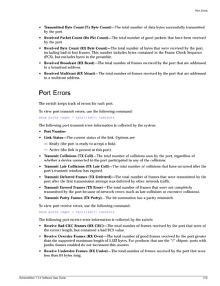
![Status Monitoring and Statistics
• Receive Fragmented Frames (RX Frag)—The total number of frames received by the port were of
incorrect length and contained a bad FCS value.
• Receive Jabber Frames (RX Jab)—The total number of frames received by the port that was of
greater than the support maximum length and had a Cyclic Redundancy Check (CRC) error.
• Receive Alignment Errors (RX Align)—The total number of frames received by the port that occurs
if a frame has a CRC error and does not contain an integral number of octets.
• Receive Frames Lost (RX Lost)—The total number of frames received by the port that were lost
because of buffer overflow in the switch.
Port Monitoring Display Keys
Table 29 describes the keys used to control the displays that appear when you issue any of the show
port commands.
Table 29: Port Monitoring Display Keys
Key(s) Description
U Displays the previous page of ports.
D Displays the next page of ports.
[Esc] or [Return] Exits from the screen.
0 Clears all counters.
[Space] Cycles through the following screens:
• Packets per second
• Bytes per second
• Percentage of bandwidth
Available using the show port utilization command only.
System Temperature
You can record the system temperature in celsius for the BlackDiamond and Alpine systems to the
syslog. The temperature is recorded every hour.
To record the temperature, use the following command:
enable temperature-logging
By default, the system temperature is not recorded to the syslog.
After you enable the temperature logging feature, you can view the temperature of the system. To view
the temperature, use the following command:
show log
The following is sample temperature output from the show log command:
06/12/2003 19:50:59.00 <Info:ELRP> Current temperature reading [197] is 49C.
06/12/2003 18:50:59.00 <Info:ELRP> Current temperature reading [196] is 48C.
214 ExtremeWare 7.2.0 Software User Guide](https://image.slidesharecdn.com/extremewareuserguide72-110124002726-phpapp01/85/Extreme-wareuserguide72-214-320.jpg)
![System Health Checking
06/12/2003 17:50:59.00 <Info:ELRP> Current temperature reading [195] is 48C.
To stop recording the temperature, use the following command:
disable temperature-logging
If you already enabled temperature logging, and you want to view the current temperature of the
system, do the following:
1 Disable the temperature logging feature using the following command:
disable temperature-logging
2 Re-enable the temperature logging feature using the following command:
enable temperature-logging
3 Display the syslog using the following command:
show log
System Health Checking
The system health checker tests the backplane, the CPU, and I/O modules by periodically forwarding
packets and checking for the validity of the forwarded packets.
The system health checker can be configured to handle a failure as an error condition, logging the
problem to the syslog, or it can attempt auto-recovery of the module that generated the errors.
The alarm-level and auto-recovery options are mutually exclusive.
To enable the system health checker, use the following command:
enable sys-health-check
To disable the system health checker, use the following command:
disable sys-health-check
To configure the switch to respond to a failed health check based on an alarm-level, use the following
command:
configure sys-health-check alarm-level [log | system-down | traps | default |
auto-recovery <number of tries> [online | offline]]
This command provides the following options:
• card-down—Posts a CRIT message to the log, sends a trap, and turns off the module.
• log—Posts a CRIT message to the log.
• system-down—Posts a CRIT message to the log, sends a trap, and turns off the system.
• traps—Posts a CRIT message to the log and sends a trap.
The default option is log.
To configure the switch for auto-recovery, use the following command:
ExtremeWare 7.2.0 Software User Guide 215](https://image.slidesharecdn.com/extremewareuserguide72-110124002726-phpapp01/85/Extreme-wareuserguide72-215-320.jpg)
![Status Monitoring and Statistics
configure sys-health-check auto-recovery <number> [offline | online] | alarm-level
[card-down | default | log | system-down | traps]
The auto-recovery option is used to configure the number of times the system health checker attempts
to automatically reset a faulty module and bring it online. If the module continues to fail more than the
configured number of attempts, the system health checker sets the module to card-down.
When auto-recovery is configured, the occurrence of three consecutive checksum errors will cause a
packet memory (PM) defect detection program to be run against the I/O module. Checksum errors can
include internal and external MAC port parity errors, EDP checksum errors, and CPU packet or
diagnostic packet checksum errors. If defects are detected, the card is taken offline, the memory defect
information is recorded in the card EEPROM, the defective buffer is mapped out of further use, and the
card is returned to operational state. A maximum of 8 defects can be stored in the EEPROM.
After the PM defect detection and mapping process has been run, a card is considered failed and is
taken offline in the following circumstances:
• More than eight defects are detected.
• Three consecutive checksum errors were detected by the health checker, but no new PM defects were
found by the PM defect detection process.
• After defects were detected and mapped out, the same checksum errors are again detected by the
system health checker.
The auto-recovery repetition value is ignored in these cases. In any of these cases, please contact
Extreme Technical Support.
To view the status of the system health checker, use the following command:
show diagnostics
Checking the Integrity of the FDB
The system health checker also checks the integrity of the FDB. If you enable the system health checker,
a section of the FDB memory on each module’s switching fabric is non-intrusively compared to the
software copy of the FDB. The switch takes one of the following actions if it detects a bad entry:
• If the entry is not in use—remaps around the entry location
• If the entry is in use, but is safely removable (most MAC and IP-DA entries)—removes the
questionable entry, allows the table to be rebuilt naturally, and remaps around the entry location
• If the entry is in use and is not safely removable (MAC_NH, IPSA, IPMCDA, IPDP, IPSP,
IPXSN)—sends a warning message to the log
If the switch detects more than eight questionable entries, it executes the configured failure action and
stops remapping on the switch fabric. To see the questionable and remapped entries, use the show fdb
command. The following information is displayed:
• Questionable entries are marked with a “Q” flag
• Remapped entries are marked with an “R” flag
• Total FDB count
You can also display FDB scan statistics using the following commands:
show diagnostics sys-health-check
216 ExtremeWare 7.2.0 Software User Guide](https://image.slidesharecdn.com/extremewareuserguide72-110124002726-phpapp01/85/Extreme-wareuserguide72-216-320.jpg)
![System Health Checking
To clear the questionable and remapped entries, use the following command:
clear fdb remap
Testing the Transceivers
The transceiver test is a useful diagnostic tool that allows you to test the integrity of the transceivers
used for communication between the ASICS and the CPU on an MSM or SMMi module. The transceiver
test is available on modular switches only.
Enabling the Transceiver Test
By default, transceiver testing is disabled. To enable the transceiver test on an Alpine switch, use the
following command:
enable transceiver-test [all | slot <slot number> {backplane} | msm-a | msm-b]
To enable the transceiver test on a BlackDiamond switch, use the following command:
enable transceiver-test [all | slot <slot number> {backplane} | msm-a | msm-b]
where the following is true:
• all—Specifies all of the slots in the chassis.
• backplane—Specifies the backplane of the Alpine chassis. This is available on Alpine switches only.
• slot number—Specifies the slot number of the module to scan.
• msm-a—Specifies the MSM installed in slot A. This is available on BlackDiamond switches only.
• msm-b—Specifies the MSM installed in slot B. This is available on BlackDiamond switches only.
To determine if you have the transceiver test enabled and the failure action the switch takes, use the
show switch command. The following is sample transceiver test output:
Transceiver Diag: Enabled. Failure action: log only
Disabling the Transceiver Test
To disable the transceiver test on an Alpine switch, use the following command:
disable transceiver-test [all | slot <slot number> {backplane} | msm-a | msm-b]
To disable the transceiver test on a BlackDiamond switch, use the following command:
disable transceiver-test [all | slot <slot number> {backplane} | msm-a | msm-b]
Configuring the Transceiver Test Parameters
You can configure the following test parameters:
• How often the test runs
• The amount of errors accepted
• The number of 20-second windows the switch uses to check for errors
• The action the switch takes if too many failures are detected
ExtremeWare 7.2.0 Software User Guide 217](https://image.slidesharecdn.com/extremewareuserguide72-110124002726-phpapp01/85/Extreme-wareuserguide72-217-320.jpg)
![System Health Checking
To configure the action the switch takes when too many failures are detected, use the following
command:
configure transceiver-test failure-action [log | sys-health-check]
where the following is true:
• log—Messages are sent to the syslog. Only one instance of an error messages is logged at this level.
This is the default.
• sys-health-check—The configured system health check action is taken.
To return the switch to the default mode of sending messages to the syslog, use the following
command:
unconfigure transceiver-test failure-action
For more information about these and other transceiver test commands, see the Extreme Networks
Command Reference Guide.
Displaying Transceiver Statistics
To view the transceiver statistics, use the following command:
show diagnostics
In addition to other switch diagnostics, you can view the following transceiver statistics:
• Slot number or backplane
• Cardtype (if no module is installed in the slot, the card type is unknown)
• Cardstate
• Test
• Pass
• Fail
• Time of the last failure
The following is an example of the type of transceiver statistics output displayed:
Transceiver system health diag result
Pass/Fail Counters Are in HEX
Slot Cardtype Cardstate Test Pass Fail Time_last_fail
---- -------- --------- ---- -------- -------- --------------
slot 1 Unknown
slot 2 WM4T1 Operational MAC 7d456 0
slot 3 FM8V Operational MAC 7d456 0
slot 4 GM4X Operational MAC 7d456 0
BPLNE SMMI Operational UART 7d454 0
BPLNE SMMI Operational FLASH 7d454 0
BPLNE SMMI Operational SRAM 7d454 0
BPLNE SMMI Operational NVRAM 7d454 0
BPLNE SMMI Operational ENET 7d454 0
BPLNE Basbrd Operational QUAKE 7d454 0
BPLNE Basbrd Operational TWISTER 7d454 0
To clear the transceiver statistics, use the following command:
ExtremeWare 7.2.0 Software User Guide 219](https://image.slidesharecdn.com/extremewareuserguide72-110124002726-phpapp01/85/Extreme-wareuserguide72-219-320.jpg)
![Status Monitoring and Statistics
clear transceiver-test
Setting the System Recovery Level
You can configure the system to automatically reboot after a software task exception, using the
following command:
configure sys-recovery-level [none | [all | critical] [msm-failover | reboot |
shutdown | system-dump [maintenance-mode | msm-failover | reboot | shutdown]]]
Where the following is true:
• none—Configures the level to no recovery.
• all—Configures ExtremeWare to log an error into the syslog and automatically reboot the system
after any task exception.
• critical—Configures ExtremeWare to log an error into the syslog and automatically reboot the
system after a critical task exception.
The default setting is none.
Event Management System/Logging
Beginning in ExtremeWare 7.1.0, the system responsible for logging and debugging was updated and
enhanced. We use the general term, event, for any type of occurrence on a switch which could generate
a log message, or require an action. For example, a link going down, a user logging in, a command
entered on the command line, or the software executing a debugging statement, are all events that
might generate a log message. The new system for saving, displaying, and filtering events is called the
Event Management System (EMS). With EMS, you have a lot more options about which events generate
log messages, where the messages are sent, and how they are displayed. Using EMS you can:
• send event messages to a number of logging targets (for example, syslog host and NVRAM)
• filter events on a per-target basis
— by component, subcomponent, or specific condition (for example, BGP messages, IGMP.Snooping
messages, or the IP.Forwarding.SlowPathDrop condition)
— by match expression (for example, any messages containing the string “user5”)
— by matching parameters (for example, only messages with source IP addresses in the 10.1.2.0/24
subnet)
— by severity level (for example, only messages of severity critical, error, or warning)
• change the format of event messages (for example, display the date as “12-May-2003” or
“2003-05-12”)
• display log messages in real-time, and filter the messages that are displayed, both on the console and
from telnet sessions
• display stored log messages from the memory buffer or NVRAM
• upload event logs stored in memory to a TFTP server
• display counts of event occurrences, even those not included in filter
• display debug information, using a consistent configuration method
220 ExtremeWare 7.2.0 Software User Guide](https://image.slidesharecdn.com/extremewareuserguide72-110124002726-phpapp01/85/Extreme-wareuserguide72-220-320.jpg)
![Event Management System/Logging
Sending Event Messages to Log Targets
There are five types of targets that can receive log messages:
• console display
• current session (telnet or console display)
• memory buffer (can contain 200-20,000 messages)
• NVRAM (messages remain after reboot)
• syslog host
The first four types of targets exist by default, but before enabling any syslog host, the host’s
information needs to be added to the switch using the configure syslog command. Extreme
Networks EPICenter can be a syslog target.
By default, the memory buffer and NVRAM targets are already enabled and receive messages. To start
sending messages to the targets, use the following command:
enable log target [console-display | memory-buffer | nvram | session | syslog [<host
name/ip> {:<udp-port>} [local0 ... local7]]]
Once enabled, the target receives the messages it is configured for. See the section “Target
Configuration” for information on viewing the current configuration of a target. The memory buffer can
only contain the configured number of messages, so the oldest message is lost when a new message
arrives, and the buffer is full.
Use the following command to stop sending messages to the target:
disable log target [console-display | memory-buffer | nvram | session | syslog
[<host name/ip> {:<udp-port>} [local0 ... local7]]]
NOTE
Refer to your UNIX documentation for more information about the syslog host facility.
Filtering Events Sent to Targets
Not all event messages are sent to every enabled target. Each target receives only the messages that it is
configured for.
Target Configuration
To specify the messages to send to a enabled target, you will set a message severity level, a filter name,
and a match expression. These items determine which messages are sent to the target. You can also
configure the format of the messages in the targets. Each target has a default configuration that mimics
the expected behavior of prior ExtremeWare releases. For example, the console display target is
configured to get messages of severity info and greater, the NVRAM target gets messages of severity
warning and greater, and the memory buffer target gets messages of severity debug-data and greater.
All the targets are associated by default with a filter named DefaultFilter, that passes all events at or
above the default severity threshold, like the behavior of earlier releases (the earlier releases had no
filters). All the targets are also associated with a default match expression that matches any messages
(the expression that matches any message is displayed as Match : (none) from the command line).
And finally, each target has a format associated with it.
ExtremeWare 7.2.0 Software User Guide 221](https://image.slidesharecdn.com/extremewareuserguide72-110124002726-phpapp01/85/Extreme-wareuserguide72-221-320.jpg)
![Status Monitoring and Statistics
To display the current log configuration of the targets, use the following command:
show log configuration target {console-display | memory-buffer | nvram | session |
syslog <host name/ip> {: <udp-port>}[local0 ... local7]}
To configure a target, there are specific commands for filters, formats, and severity that are discussed in
the following sections.
Severity
Messages are issued with one of the severity level specified by the standard BSD syslog values
(RFC 3164), critical, error, warning, notice, and info, plus three severity levels for extended
debugging, debug-summary, debug-verbose, and debug-data. Note that RFC 3164 syslog values
emergency and alert are not needed since critical is the most severe event in the system.
The three severity levels for extended debugging, debug-summary, debug-verbose, and debug-data,
require that debug mode be enabled (which may cause a performance degradation). See the section
“Displaying Debug Information” for more information about debugging.
Table 30: Severity Levels Assigned by the Switch1
Level Description
Critical A serious problem has been detected which is compromising the operation of the
system and that the system can not function as expected unless the situation is
remedied. The switch may need to be reset.
Error A problem has been detected which is interfering with the normal operation of the
system and that the system is not functioning as expected.
Warning An abnormal condition, not interfering with the normal operation of the system, has
been detected which may indicate that the system or the network in general may not
be functioning as expected.
Notice A normal but significant condition has been detected, which signals that the system is
functioning as expected.
Info (Informational) A normal but potentially interesting condition has been detected, which signals that the
system is functioning as expected and simply provides potentially detailed information
or confirmation.
Debug-Summary A condition has been detected that may interest a developer determining the reason
underlying some system behavior.
Debug-Verbose A condition has been detected that may interest a developer analyzing some system
behavior at a more verbose level than provided by the debug summary information.
Debug-Data A condition has been detected that may interest a developer inspecting the data
underlying some system behavior.
1. In ExtremeWare version 7.1.0, the levels alert and emergency were deprecated. The equivalent level is critical.
To configure the severity level of the messages sent to a target, there is more than one command that
you can use. The most direct way to set the severity level of all the sent messages is to use the following
command:
configure log target [console-display | memory-buffer | nvram | session |
syslog [<host name/ip> {: <udp-port>} [local0 ... local7]]]
filter <filter name> {severity <severity> {only}}
When you specify a severity level, messages of that severity and greater will be sent to the target. If you
want only messages of the specified severity to be sent to the target, use the keyword only. For
222 ExtremeWare 7.2.0 Software User Guide](https://image.slidesharecdn.com/extremewareuserguide72-110124002726-phpapp01/85/Extreme-wareuserguide72-222-320.jpg)
![Event Management System/Logging
example, specifying severity warning will send warning, error, and critical messages, but specifying
severity warning only will just send warning messages.
Another command that can be used to configure severity levels is the command used to associate a
filter with a target:
configure log target [console-display | memory-buffer | nvram | session |
syslog [<host name/ip> {: <udp-port>} [local0 ... local7]]]
filter <filter name> {severity <severity> {only}}
When you specify a severity level as you associate a filter with a target, you further restrict the
messages reaching the target. The filter may only allow certain categories of messages to pass. Only the
messages that pass the filter, and then pass the specified severity level will reach the target.
Finally, you can specify the severity levels of messages that reach the target by associating a filter with a
target. The filter can specify exactly which message it will pass. Constructing a filter is discussed in the
section “Filtering By Components and Conditions”.
Components and Conditions
Beginning with the introduction of EMS in release 7.1.0, the event conditions detected by ExtremeWare
were organized into components and subcomponents. This is somewhat similar to the fault log
subsystems used in previous versions. Not all conditions have been placed in the
component/subcomponent structure of EMS, but all the conditions will be moved over time into this
structure. To get a listing of the components and subcomponents in your release of ExtremeWare, use
the following command:
show log components {<event component> | all}
For example, to get a listing of the subcomponents that make up the STP component, use the following
command:
show log components stp
The output produced by the command is similar to the following:
Severity
Component Title Threshold
------------------- ---------------------------------------------- ----------
STP Spanning-Tree Protocol (STP) Error
InBPDU STP In BPDU subcomponent Warning
OutBPDU STP Out BPDU subcomponent Warning
System STP System subcomponent Error
In the display above is listed the component, the subcomponents that make up that component, and the
default severity threshold assigned to that component. A period (.) is used to separate component,
subcomponent, and condition names in EMS. For example, you can refer to the InBPDU subcomponent
of the STP component as STP.InBPDU. On the CLI, you can abbreviate or TAB complete any of these.
A component or subcomponent will often have several conditions associated with it. To see the
conditions associated with a component, use the following command:
show log events {<event condition> | [all | <event component>] {severity <severity>
{only}}} {detail}
For example, to see the conditions associated with the STP.InBPDU subcomponent, use the following
command:
ExtremeWare 7.2.0 Software User Guide 223](https://image.slidesharecdn.com/extremewareuserguide72-110124002726-phpapp01/85/Extreme-wareuserguide72-223-320.jpg)
![Event Management System/Logging
Once you have created your filter, you can then configure filter items that include or exclude events
from the filter. Included events are passed, excluded events are blocked. Use the following command to
configure your filter:
configure log filter <filter name> [add | delete] {exclude} events [<event condition>
| [all | <event component>] {severity <severity> {only}}]
For example, if you create the filter myFilter from scratch, then issue the following command:
configure log filter myFilter add events stp
all STP events will pass myFilter of at least the default threshold severity (for the STP component, the
default severity threshold is error). You can further modify this filter by specifying additional
conditions. For example, assume that myFilter is configured as before, and assume that you want to
exclude any events from the STP subcomponent, STP.OutBPDU. Use the following command to add
that condition:
configure log filter myFilter add exclude events stp.outbpdu
You can continue to modify this filter by adding more filter items. The filters process events by
comparing the event with the most recently configured filter item first. If the event matches this filter
item, the incident is either included or excluded, depending on whether the exclude keyword was
used. Subsequent filter items on the list are compared if necessary. If the list of filter items has been
exhausted with no match, the event is excluded, and is blocked by the filter.
To examine the configuration of a filter, use the following command:
show log configuration filter {<filter name>}
The output produced by the command (for the earlier filter) is similar to the following:
Log Filter Name : myFilter
I/ Severity
E Comp SubComp Condition CEWNISVD
- ------- ----------- ----------------------- --------
E STP OutBPDU * CEWNI+++
I STP * * ********
Include/Exclude: (I) Include, (E) Exclude
Severity Values: (C) Critical, (E) Error, (W) Warning, (N) Notice, (I) Info
(*) Pre-assigned severities in effect for each subcomponent
Debug Severity : (S) Debug-Summary, (V) Debug-Verbose, (D) Debug-Data
(+) Debug Severity requested, but log debug-mode not enabled
If Match parameters present:
Parameter Flags: (S) Source, (D) Destination (as applicable)
(I) Ingress, (E) Egress, (B) BGP
Parameter Types: Port - Physical Port list, Slot - Physical Slot #
MAC - MAC address, IP - IP Address/netmask, Mask - Netmask
VID - Virtual LAN ID (tag), VLAN - Virtual LAN name
L4 - Layer-4 Port #, Num - Number, Str - String
Nbr - Neighbor, Rtr - Routerid, EAPS - EAPS Domain
Strict Match : (Y) every match parameter entered must be present in the event
(N) match parameters need not be present in the event
The show log configuration filter command shows each filter item, in the order that it will be applied
and whether it will be included or excluded. The above output shows the two filter items, one
excluding events from the STP.OutBPDU component, the next including the remaining events from the
STP component. The severity value is shown as “*”, indicating that the component’s default severity
ExtremeWare 7.2.0 Software User Guide 225](https://image.slidesharecdn.com/extremewareuserguide72-110124002726-phpapp01/85/Extreme-wareuserguide72-225-320.jpg)
![Status Monitoring and Statistics
threshold controls which messages are passed. The Parameter(s) heading is empty for this filter, since
no match was configured for this filter. Matches are discussed in the section, “Matching Expressions”.
Each time a filter item is added to or deleted from a given filter, the events specified are compared
against the current configuration of the filter to try to logically simplify the configuration. Existing items
will be replaced by logically simpler items if the new item enables rewriting the filter. If the new item is
already included or excluded from the currently configured filter, the new item is not added to the filter.
Matching Expressions
You can specify that messages that reach the target match a specified match expression. The message
text is compared with the match expression to determine whether to pass the message on. To require
that messages match a match expression, is to use the following command:
configure log target [console-display | memory-buffer | nvram | session |
syslog [<host name/ip> {: <udp-port>} [local0 ... local7]]] match [any
|<match-expression>]
The messages reaching the target will match the match-expression, a simple regular expression. The
formatted text string that makes up the message is compared with the match expression, and is passed
to the target if it matches. This command does not affect the filter in place for the target, so the match
expression is only compared with the messages that have already passed the target’s filter. For more
information on controlling the format of the messages, see the section, “Formatting Event Messages”.
Simple Regular Expressions. A simple regular expression is a string of single characters including
the dot character (.), which are optionally combined with quantifiers and constraints. A dot matches any
single character while other characters match only themselves (case is significant). Quantifiers include
the star character (*) that matches zero or more occurrences of the immediately preceding token.
Constraints include the caret character (^) that matches at the beginning of a message, and the currency
character ($) that matches at the end of a message. Bracket expressions are not supported. There are a
number of sources available on the Internet and in various language references describing the operation
of regular expressions. Table 31 shows some examples of regular expressions.
Table 31: Simple Regular Expressions
Regular Expression Matches Does not match
port port 2:3 poor
import cars por
portable structure pot
..ar baar bar
bazaar
rebar
port.*vlan port 2:3 in vlan test
add ports to vlan
port/vlan
myvlan$ delete myvlan myvlan port 2:3
error in myvlan ports 2:4,3:4 myvlan link down
Matching Parameters
Rather than using a text match, ExtremeWare’s EMS allows you to filter more efficiently based on the
message parameter values. In addition to event components and conditions and severity levels, each
filter item can also use parameter values to further limit which messages are passed or blocked. The
226 ExtremeWare 7.2.0 Software User Guide](https://image.slidesharecdn.com/extremewareuserguide72-110124002726-phpapp01/85/Extreme-wareuserguide72-226-320.jpg)
![Event Management System/Logging
process of creating, configuring, and using filters has already been described in the section, “Filtering
By Components and Conditions”, so this section will discuss matching parameters with a filter item. To
configure a parameter match filter item, use the following command:
configure log target [console-display | memory-buffer | nvram | session |
syslog [<host name/ip> {: <udp-port>} [local0 ... local7]]]
filter <filter name> {severity <severity> {only}}
Each event in ExtremeWare is defined with a message format and zero or more parameter types. The
show log events detail command can be used to display event definitions (the event text and
parameter types). Only those parameter types that are applicable given the events and severity specified
are exposed on the CLI. The syntax for the parameter types (represented by <type> in the command
syntax above) is:
[bgp [neighbor | routerid] <ip address>
| eaps <eaps domain name>
| {destination | source} [ipaddress <ip address> | L4-port <L4-port>| mac-address
<mac-address>]
| {egress | ingress} [slot <slot number> | ports <portlist>]
| netmask <netmask>
| number <number>
| string <match expression>
| vlan <vlan name>
| vlan tag <vlan tag>]
The <value> depends on the parameter type specified. As an example, an event may contain a physical
port number, a source MAC address, and a destination MAC address. To allow only those Bridging
incidents, of severity notice and above, with a specific source MAC address, use the following
command:
configure log filter myFilter add events bridge severity notice match source
mac-address 00:01:30:23:C1:00
The string type is used to match a specific string value of an event parameter, such as a user name. A
string can be specified as a simple regular expression.
Use the and keyword to specify multiple parameter type/value pairs that must match those in the
incident. For example, to allow only those events with specific source and destination MAC addresses,
use the following command:
configure log filter myFilter add events bridge severity notice match source
mac-address 00:01:30:23:C1:00 and destination mac-address 01:80:C2:00:00:02
Match Versus Strict-Match. The match and strict-match keywords control the filter behavior for
incidents whose event definition does not contain all the parameters specified in a configure log
filter events match command. This is best explained with an example. Suppose an event in the
XYZ component, named XYZ.event5, contains a physical port number, a source MAC address, but no
destination MAC address. If you configure a filter to match a source MAC address and a destination
MAC address, XYZ.event5 will match the filter when the source MAC address matches regardless of the
destination MAC address, since the event contains no destination MAC address. If you specify the
strict-match keyword, then the filter will never match event XYZ.event5, since this event does not
contain the destination MAC address.
In other words, if the match keyword is specified, an incident will pass a filter so long as all parameter
values in the incident match those in the match criteria, but all parameter types in the match criteria
need not be present in the event definition.
ExtremeWare 7.2.0 Software User Guide 227](https://image.slidesharecdn.com/extremewareuserguide72-110124002726-phpapp01/85/Extreme-wareuserguide72-227-320.jpg)
![Status Monitoring and Statistics
Formatting Event Messages
Event messages are made up of a number of items. The individual items can be formatted, however,
EMS does not allow you to vary the order of the items. To format the messages for a particular target,
use the following command:
configure log target [console-display | memory-buffer | nvram | session |
syslog [<host name/ip> {:<udp-port>} [local0 ... local7]]]
format [timestamp [seconds | hundredths | none]
| date [dd-mm-yyyy | dd-Mmm-yyyy | mm-dd-yyyy | Mmm-dd | yyyy-mm-dd | none]
| severity [on | off]
| event-name [component | condition | none | subcomponent]
| host-name [on | off]
| priority [on | off]
| tag-id [on | off]
| tag-name [on | off]
| sequence-number [on | off]
| process-name [on | off]
| process-id [on | off]
| source-function [on | off]
| source-line [on | off]]
Using the default format for the session target, an example log message might appear as:
05/29/2003 12:15:25.00 <Warn:SNTP.RslvSrvrFail> The SNTP server parameter value
(TheWrongServer.example.com) can not be resolved.
If you set the current session format using the following command:
configure log target session format date mm-dd-yyy timestamp seconds event-name
component
The same example would appear as:
05/29/2003 12:16:36 <Warn:SNTP> The SNTP server parameter value
(TheWrongServer.example.com) can not be resolved.
In order to provide some detailed information to technical support, you set the current session format
using the following command:
configure log target session format date mmm-dd timestamp hundredths event-name
condition source-line on process-name on
The same example would appear as:
May 29 12:17:20.11 SNTP: <Warn:SNTP.RslvSrvrFail> tSntpc: (sntpcLib.c:606) The SNTP
server parameter value (TheWrongServer.example.com) can not be resolved.
Displaying Real-Time Log Messages
You can configure the system to maintain a running real-time display of log messages on the console
display or on a (telnet) session. To turn on the log display on the console, use the console-display
option inthe following command:
enable log target [console-display | memory-buffer | nvram | session | syslog [<host
name/ip> {:<udp-port>} [local0 ... local7]]]
This setting may be saved to the FLASH configuration and will be restored on boot up (to the
console-display session).
228 ExtremeWare 7.2.0 Software User Guide](https://image.slidesharecdn.com/extremewareuserguide72-110124002726-phpapp01/85/Extreme-wareuserguide72-228-320.jpg)
![Event Management System/Logging
To turn on log display for the current session:
enable log target session
This setting only affects the current session, and is lost when you log off the session.
The messages that are displayed depend on the configuration and format of the target. See the section,
“Filtering Events Sent to Targets”, for information on message filtering, and the section, “Formatting
Event Messages”, for information on message formatting.
Displaying Events Logs
The log stored in the memory buffer and the NVRAM can be displayed on the current session (either
the console display or telnet). Use the following command to display the log:
show log {messages [memory-buffer | nvram]} {severity <severity> {only}}
{starting [date <date> time <time> | date <date> | time <time>]} {ending [date
<date> time <time> | date <date> | time <time>]} {match <match-expression>}
{format <format>} {chronological}
There are many options you can use to select the log entries of interest. You can select to display only
those messages that conform to the specified:
• severity
• starting and ending date and time
• match expression
The displayed messages can be formatted differently from the format configured for the targets, and
you can choose to display the messages in order of newest to oldest, or in chronological order (oldest to
newest).
Uploading Events Logs
The log stored in the memory buffer and the NVRAM can be uploaded to a TFTP server. Use the
following command to upload the log:
upload log <host name/ip> <filename> {messages [memory-buffer | nvram]}
{severity <severity> {only}} {starting [date <date> time <time> | date <date>
| time <time>]} {ending [date <date> time <time> | date <date> | time <time>]}
{match <match-expression>} {format <format>} {chronological}
You must specify the TFTP host and the filename to use in uploading the log. There are many options
you can use to select the log entries of interest. You can select to upload only those messages that
conform to the specified:
• severity
• starting and ending date and time
• match expression
The uploaded messages can be formatted differently from the format configured for the targets, and you
can choose to upload the messages in order of newest to oldest, or in chronological order (oldest to
newest).
ExtremeWare 7.2.0 Software User Guide 229](https://image.slidesharecdn.com/extremewareuserguide72-110124002726-phpapp01/85/Extreme-wareuserguide72-229-320.jpg)
![Status Monitoring and Statistics
Displaying Counts of Event Occurrences
EMS adds the ability to count the number of occurrences of events. Even when an event is filtered from
all log targets, the event is counted. (The exception to this is events of any of the debug severities,
which are only counted when the log debug mode is enabled.) To display the event counters, use the
following command:
show log counters {<event condition> | [all | <event component>] {severity <severity>
{only}}}
Two counters are displayed. One counter displays the number of times an event has occurred, and the
other displays the number of times that notification for the event was made to the system for further
processing. Both counters reflect totals accumulated since reboot or since the counters were cleared
using the clear log counters or clear counters command.
This command also displays an included count (the column titled In in the output). The reference
count is the number of enabled targets receiving notifications of this event without regard to matching
parameters.
The keywords included, notified, and occurred only display events with non-zero counter values for
the corresponding counter.
Output of the command:
show log counters stp.inbpdu severity debug-summary
will be similar to the following:
Comp SubComp Condition Severity Occurred In Notified
------- ----------- ----------------------- ------------- -------- -- --------
STP InBPDU
Drop Error 0 1 0
Ign Debug-Summary 0+ 0 0
Trace Info 0 0 0
Occurred : # of times this event has occurred since last clear or reboot
Flags : (+) Debug events are not counted while log debug-mode is disabled
In(cluded): # of enabled targets whose filter includes this event
Notified : # of times this event has occurred when 'Included' was non-zero
Output of the command:
show log counters stp.inbpdu.drop
will be similar to the following:
Comp SubComp Condition Severity Occurred In Notified
------- ----------- ----------------------- ------------- -------- -- --------
STP InBPDU
Drop Error 0 1 0
Displaying Debug Information
By default, a switch will not generate events of severity Debug-Summary, Debug-Verbose, and
Debug-Data unless the switch is in debug mode. Debug mode causes a performance penalty, so it
should only be enabled for specific cases where it is needed. To place the switch in debug mode, use the
following command:
enable log debug-mode
230 ExtremeWare 7.2.0 Software User Guide](https://image.slidesharecdn.com/extremewareuserguide72-110124002726-phpapp01/85/Extreme-wareuserguide72-230-320.jpg)
![Event Management System/Logging
Once debug mode is enabled, any filters configured for your targets will still affect which messages are
passed on or blocked.
NOTE
Previous versions of ExtremeWare used the debug-trace command to enable debugging. Not all
systems in ExtremeWare were converted to use EMS in the initial release. As a result, some debug
information still requires you to use the corresponding debug-trace command. The show log component
command displays the systems in your image that are part of EMS. Any systems in EMS will not have
debug-trace commands, and vice-versa
Compatibility with previous ExtremeWare commands
Since EMS provides much more functionality, there are a number of new commands introduced to
support it. However, if you do not require the enhanced capabilities provided by EMS, you can continue
to use many of the logging commands that existed in earlier versions of ExtremeWare. For consistency,
the earlier commands are still supported. Listed below are earlier commands with their new command
equivalents.
Enable / disable log display
The following commands related to the serial port console:
enable log display
disable log display
are equivalent to using the console-display option in the following commands:
enable log target [console-display | memory-buffer | nvram | session | syslog [<host
name/ip> {:<udp-port>} [local0 ... local7]]]
disable log target [console-display | memory-buffer | nvram | session | syslog
[<host name/ip> {:<udp-port>} [local0 ... local7]]]
Note that the existing command enable log display applies only to the serial port console. Since the
ability to display log messages on other sessions was added, the target name session was chosen. For
clarity, the target name console-display was chosen to refer to the serial port console, previously
referred to as simply display.
Configure log display
The following command related to the serial port console:
configure log display {<severity>}
is equivalent to:
configure log target console-display severity <severity>
Remote syslog commands
The following command related to remote syslog hosts:
ExtremeWare 7.2.0 Software User Guide 231](https://image.slidesharecdn.com/extremewareuserguide72-110124002726-phpapp01/85/Extreme-wareuserguide72-231-320.jpg)
![Status Monitoring and Statistics
configure syslog {add} <host name/ip> {: <udp-port>} [local0 ... local7] {<severity>}
is equivalent to the following two commands:
configure syslog add <hostname/IP> {: <udp-port>} [local0 ... local7]
configure log target syslog <hostname/IP> {: <udp-port>} [local0 ... local7] severity
<severity>
NOTE
Refer to your UNIX documentation for more information about the syslog host facility.
Logging Configuration Changes
ExtremeWare allows you to record all configuration changes and their sources that are made using the
CLI by way of telnet or the local console. The changes cause events that are logged to the target logs.
Each log entry includes the user account name that performed the change and the source IP address of
the client (if telnet was used). Configuration logging applies only to commands that result in a
configuration change. To enable configuration logging, use the following command:
enable cli-config-logging
To disable configuration logging, use the following command:
disable cli-config-logging
CLI configuration logging is enabled by default.
Configuring and Monitoring Flow Statistics
NOTE
This section describes the process of configuring and monitoring flow statistics on Ethernet links. If you
plan to configure and monitor flow statistics on PoS links, see the Packet Over SONET Installation and
User Guide for more information.
The broad growth in Internet and intranet usage has brought with it an increased demand for network
bandwidth and performance that is based on predictable quality of service and security. This movement
is paralleled by the related need for measurement technology that makes it possible to gather, analyze,
and manipulate information about network and application use. NetFlow, originally developed by
Cisco, provides a way for a switch to capture and export traffic classification or precedence information
as data traverses, or flows, across portions of a network.
A network flow is defined as a unidirectional sequence of packets between a particular source device
and destination device that share the same protocol and transport-layer information. Flows are defined
by the following fields: source IP address, destination IP address, source port, destination port, and
protocol type. Per-flow statistics are useful for many management purposes, including:
• Accounting and billing
• Network capacity planning and trend analysis
• Network monitoring
232 ExtremeWare 7.2.0 Software User Guide](https://image.slidesharecdn.com/extremewareuserguide72-110124002726-phpapp01/85/Extreme-wareuserguide72-232-320.jpg)
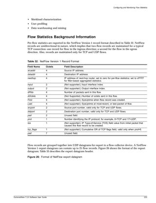

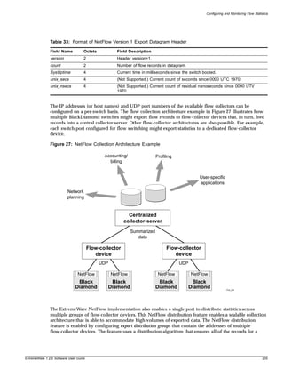
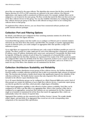
![Configuring and Monitoring Flow Statistics
Export Criteria
For Ethernet ports, flow records are exported on an age basis. If the age of the flow is greater than a
configurable time, the record is exported.
An Ethernet port configured for flow switching transmits a NetFlow Export Datagram when 25 flow
records are ready for export, or when at least one flow has been awaiting export for one second.
An Ethernet port configured for capturing flows transmits NetFlow export datagrams when the
configured time-out expires and exports the data collected by the flow filters configured on that port.
As the NetFlow on Ethernet links is modeled as port-based, individual ports maintain their configured
time-outs and export the flows collected by the configured flow filters on the expiry of flow export
time-out.
Enabling and Disabling the Flow Statistics Feature on a Switch
To enable the flow statistics feature on a switch, use the following command:
enable flowstats
The flow statistics feature is disabled by default.
To disable the flow statistics feature on a switch, use the following command:
disable flowstats
Enabling and Disabling Flow Statistics on a Port
To enable the flow statistics function on the specified port, use the following command:
enable flowstats ports <portlist>
The flow statistics function is disabled by default.
To disable the flow statistics function on the specified port, use the following command:
disable flowstats ports <portlist>
Configuring the Export Destination
A single port can distribute statistics across multiple groups of flow-collector devices. This NetFlow
distribution capability makes it possible to create a collection architecture that scales to accommodate
high volumes of exported data. It also offers a health-checking function that improves the reliability of
the collection architecture by ensuring that only responsive flow-collector devices are included in active
export distribution lists. The distribution algorithm also ensures that all the ingress flow records for a
given flow are exported to the same collector.
NetFlow distribution is enabled by configuring export distribution groups that identify the addresses of
multiple flow-collector devices. You can configure up to 32 export distribution groups on a
BlackDiamond 6800 series switch, and each group can contain as many as eight flow-collector devices.
To configure the export groups and flow-collector devices to which NetFlow datagrams are exported,
use the following command:
configure flowstats export <group#> [add | delete] [<ipaddress> | <hostname>]
<udp_port>
ExtremeWare 7.2.0 Software User Guide 237](https://image.slidesharecdn.com/extremewareuserguide72-110124002726-phpapp01/85/Extreme-wareuserguide72-237-320.jpg)
![Status Monitoring and Statistics
The group# parameter is an integer in the range from 1 through 32 that identifies the specific group for
which the destination is being configured.
You can use the add and delete keywords to add or delete flow-collector destinations.
To export NetFlow datagrams to a group, you must configure at least one flow-collector destination. By
default, no flow-collector destinations are configured. To configure a flow-collector destination, use
either an IP address and UDP port number pair or a hostname and UDP port number pair to identify
the flow-collector device to which NetFlow export datagrams are to be transmitted. You can configure
up to eight flow-collector destinations for each group. When multiple flow-collectors are configured as
members of the same group, the exported NetFlow datagrams are distributed across the available
destinations.
Configuring the Source IP Address
To configure the IP address that is to be used as the source IP address for NetFlow datagrams to be
exported, use the following command:
configure flowstats source ipaddress <ipaddress>
By default, flow records are exported with the VLAN interface address that has a route to the
configured flow-collector device. Depending on how it is configured, a flow-collector device can use the
source IP address of received NetFlow datagrams to identify the switch that sent the information.
The following command example specifies that the IP address 192.168.100.1 is to be used as the source
IP address for exported NetFlow datagrams.
configure flowstats source ipaddress 192.168.100.1
Configuring Flow Record Time-out
Flow records are exported on an age basis. If the age of the flow record is greater than the configured
time-out, the record is exported.
To configure the time-out value for flow records on the specified port, use the following command:
configure flowstats timeout <minutes> ports [<portlist> | all]
The time-out value is the number of minutes to use in deciding when to export flow records. The
default time-out is 5 minutes.
The following command example specifies a 10-minute time-out for exported NetFlow datagrams on
port 1 of the Ethernet module installed in slot 8 of the BlackDiamond switch.
configure flowstats timeout 10 ports 8:1
Configuring a Flow Record Filter
You can configure an Ethernet port to maintain statistics selectively for only those flows that match a
specified filter. Each Ethernet port supports eight filters for ingress flows.
To configure a flow record filter for the specified Ethernet port, use the following command:
configure flowstats filter <filter#> {aggregation} {export <group#>} ports <portlist>
[ingress | egress] <filterspec>
238 ExtremeWare 7.2.0 Software User Guide](https://image.slidesharecdn.com/extremewareuserguide72-110124002726-phpapp01/85/Extreme-wareuserguide72-238-320.jpg)
![Configuring and Monitoring Flow Statistics
where:
filter# The filter# parameter is an integer in the range from 1 to 8 that identifies the filter being
defined.
<group#> Specifies the group number that identifies the set of flow collector devices to which records
for flows matching the filter are to be exported. If Group is not specified, then group # 1 will
be used as default export group.
aggregation To reduce the volume of exported data, use this optional keyword to maintain a single set
of statistics for all the flows that match the specified filter.
filterspec Specifies a set of five parameters (four are value/mask pairs) that define the criteria by
which a flow is evaluated to determine if it should be exported. The parameters are:
[{dest-ip <ipaddress_value/mask ipaddress_filtermask>} {source-ip
<ipaddress_value/mask ipaddress_filtermask>} {dest-port
<port_value/port_filtermask>} {source-port
<port_value/port_filtermask>} {protocol
<tcp/udp/ip/protocol_value/protocol_filtermask>} | match-all-flows
|match-no-flows]
All five specifications must be included in the order specified.
The range for port/port_mask is calculated using the following formula:
(minport = port, maxport = 2^(32-port_mask)-1).
Conceptually, the filters work by ANDing the contents of each of the five components of a
forwarded flow with the associated masks from the first defined filter (filter #1). Statistics are
maintained if the results of the AND operations match the configured filter values for all
fields of the sequence. If there is no match, then the operation is repeated for filter #2, and
so on. If there is no match for any of the filters, then statistics are not maintained for the
flow. Filters for any or all of the sequence components can be configured with a single
command.
match-all-flows Specifies that the filter should match any flow.
match-no-flows Specifies that the filter should discard all flow. This option is not valid for Ethernet blades.
egress Specifies that the filter should capture only egress traffic. This option is not valid for
Ethernet blades.
ingress Specifies that the filter should capture only ingress traffic.
The following command example configures a filter to collect aggregate statistics for all traffic flowing
through ports 1-8 from the 192.170.0.0/16 subnet to the 192.171.132.0/24 subnet:
configure flowstats filter 2 aggregation export 1 ports 1-8 ingress dest-ip
192.171.132.0/24 source-ip 192.170.0.0/16 dest-port 0/0 source-port 0/0 protocol ip
Likewise, the following command example configures a filter to collect aggregate statistics for all ingress
traffic flowing from the 192.171.0.0/16 subnet to the 192.170.0.0/16 subnet and export the flows to
group 3 for ports 6:1, 7:9, and 8:42
configure flowstats filter 2 aggregation export 3 ports 6:1,7:9,8:42 ingress dest-ip
192.170.0.0/16 source-ip 192.171.0.0/16 dest-port 0/0 source-port 0/0 protocol ip
Finally, the following command configures filter 3 to collect statistics on any flows for ports 4-32 that
did not match the filters defined in the two previous commands:
configure flowstats filter 3 aggregation export 1 ports 4-32 ingress match-all-flows
ExtremeWare 7.2.0 Software User Guide 239](https://image.slidesharecdn.com/extremewareuserguide72-110124002726-phpapp01/85/Extreme-wareuserguide72-239-320.jpg)
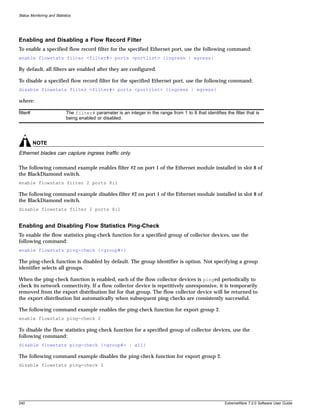
![Configuring and Monitoring Flow Statistics
Unconfiguring Flow Statistics
To reset the flow statistics configuration parameters for a specified Ethernet port to their default values,
use the following command:
unconfigure flowstats ports [<portlist> | all]
NOTE
This command does not affect the enabled or disabled status of flow statistics collection, nor does it
affect the configured export destinations.
The following command example resets the flow statistics configuration parameters for port 1 of the
module installed in slot 8 of the BlackDiamond switch to their default values.
unconfigure flowstats ports 8:1
Displaying Flow Statistics Status Information
To display status information for the flow statistics function, use the following command:
show flowstats <portlist>
where:
detail Use this optional keyword to display detailed NetFlow configuration information.
group# Use this optional parameter with the group keyword to display status information for a
specific export group.
portlist Use this optional parameter to specify one or more ports or slots and ports for which status
information is to be displayed.
If you enter the show flowstats command with none of the optional keywords or parameters, the
command displays a summary of status information for all ports.
The summary status display for a port shows the values for all flow statistics configuration parameters
for the port.
The summary status display for an export group includes the following information:
• Values for all configuration parameters
• Status of each export destination device
An example of show flowstats output is shown below:
# show flowstats
Flowstats enabled
Port Filter proto timeout group OverflowPkts flags
--------------------------------------------------------------------------
1:1 1 - 5 1 N/A EIA
Dest/Src Info: match-all-flows
Flags: E - Enable, D - Disable; I - Ingress, S - Egress; A - Aggregation
The detailed status display for an export group includes the summary information, plus the following
management information:
ExtremeWare 7.2.0 Software User Guide 241](https://image.slidesharecdn.com/extremewareuserguide72-110124002726-phpapp01/85/Extreme-wareuserguide72-241-320.jpg)
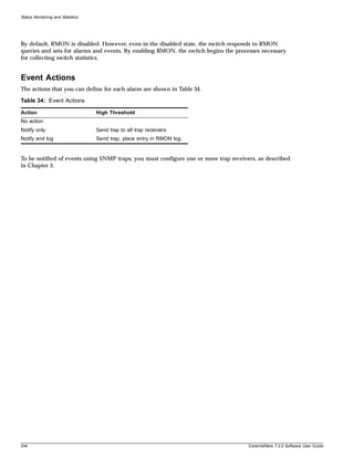
![IP Access Lists (ACLs)
NOTE
For an example of using the permit-established keyword, see “Using the Permit-Established Keyword”
on page 250.
Adding and Deleting Access List Entries
Entries can be added and deleted to the access list. To add an entry, you must supply a unique name
and, optionally, a unique precedence number. To modify an existing entry, you must delete the entry
and retype it, or create a new entry with a new unique name.
To delete an access list entry, use the following command:
delete access-list [<name> | all]
Maximum Entries
A maximum of 255 entries with an assigned precedence can be used. In addition to the 255 entries,
entries that do not use precedence can also be created, with the following restrictions:
• A source IP address must use wildcards or a completely specified mask.
• The layer 4 source and destination ports must use wildcards or be completely specified (no ranges).
• No physical source port can be specified.
• Access list rules that apply to all physical ports are implemented on all BlackDiamond I/O modules.
On a BlackDiamond switch, the maximum number of access list entries is 255 entries per I/O module.
One way to economize on the number of entries on a BlackDiamond switch is to provide a physical
ingress port as a component of an access list rule. In this case, the rule is implemented only on the I/O
modules that contain the specified ports. By restricting rules to specific I/O modules, you can extend
the number of access list rules to 5120 (NVRAM limit).
On BlackDiamond switches, there is a resource on each “i” series I/O module so that the total
maximum number of ACL entries can be up to 4080 (255*16). Each ACL must specify an ingress
physical port specific to a single I/O module to avoid using those resources on any other module.
On Alpine switches, a maximum of 255 ACL entries are supported.
Verifying Access List Configurations
To verify access list settings, you can view the access list configuration and see real-time statistics on
which access list entries are being accessed when processing traffic.
To view the access list configuration and statistics screen, use the following command:
show access-list {<name> | port <portlist>}
To initiate and refresh a running display of access list statistics, use the following command:
show access-list-monitor
ExtremeWare 7.2.0 Software User Guide 249](https://image.slidesharecdn.com/extremewareuserguide72-110124002726-phpapp01/85/Extreme-wareuserguide72-249-320.jpg)
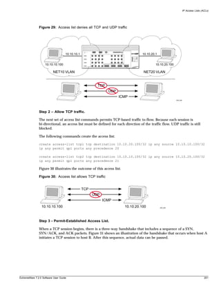
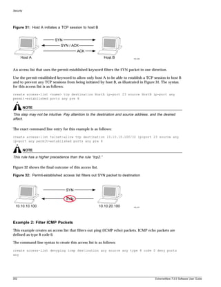
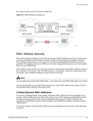
![Security
configure ports [<portlist> vlan <vlan name> | all] limit-learning <number>
This command specifies the number of dynamically-learned MAC entries allowed for these ports in this
VLAN. The range is 0 to 500,000 addresses.
When the learned limit is reached, all new source MAC addresses are blackholed at the ingress and
egress points. This prevent these MAC addresses from learning and responding to Internet control
message protocol (ICMP) and address resolution protocol (ARP) packets.
Dynamically learned entries still get aged and can be cleared. If entries are cleared or aged out after the
learning limit has been reached, new entries will then be able to be learned until the limit is reached
again.
Permanent static and permanent dynamic entries can still be added and deleted using the create
fdbentry and delete fdbentry commands. These override any dynamically learned entries.
For ports that have a learning limit in place, the following traffic will still flow to the port:
• Packets destined for permanent MAC addresses and other non-blackholed MAC addresses
• Broadcast traffic
• EDP traffic
Traffic from the permanent MAC and any other non-blackholed MAC addresses will still flow from the
virtual port.
To remove the learning limit, use the following command:
configure ports [<portlist> vlan <vlan name> | all] unlimited-learning
To verify the configuration, use the following commands:
show vlan <vlan name> security
This command displays the MAC security information for the specified VLAN.
show ports {mgmt | <portlist>} [t1 | e1 | t3] info
This command displays detailed information, including MAC security information, for the specified
port.
SNMP Traps and Syslog Messages For MAC Address Limits
To generate a syslog message and an SNMP trap when the limit is reached and a new source MAC
address attempts to participate in the network, use the following command:
enable snmp traps mac-security
The information generated should help detect unauthorized devices that attempt to access the network.
Enabling the trap also enables the syslog; there is no separate command for that. The command is a
global command; there is no per port or per VLAN control.
To disable the generation of MAC address limit SNMP traps and syslog messages, use the following
command:
disable snmp traps mac-security
254 ExtremeWare 7.2.0 Software User Guide](https://image.slidesharecdn.com/extremewareuserguide72-110124002726-phpapp01/85/Extreme-wareuserguide72-254-320.jpg)
![MAC Address Security
For more information about configuring SNMP and the MAC limit SNMP trap, see “Using SNMP” on
page 63, in Chapter 3, “Managing the Switch”.
Limiting MAC Addresses with ESRP Enabled
If you configure a MAC address limit on VLANS that have ESRP enabled, you should add an
additional back-to-back link (that has no MAC address limit on these ports) between the ESRP-enabled
switches. Doing so prevents ESRP PDU from being dropped due to MAC address limit settings.
Figure 34 is an example of configuring a MAC address limit on an ESRP-enabled VLAN.
Figure 34: MAC address limits and ESRP-enabled VLANs
ESRP 10.1.2.1 20.1.1.1
vlan
S2 20.1.2.2
S1
192.10.1.1
S4
10.1.2.2
10.1.2.100 30.1.1.2 192.10.1.100
S3
10.1.2.1 30.1.1.1
EW_081
In Figure 34, S2 and S3 are ESRP-enabled switches, while S1 is an ESRP-aware (regular layer 2) switch.
Configuring a MAC address limit on all S1 ports might prevent ESRP communication between S2 and
S3. To resolve this, you should add a back-to-back link between S2 and S3. This link is not needed if
MAC address limiting is configured only on S2 and S3, but not on S1.
MAC Address Lock Down
In contrast to limiting learning on virtual ports, you can lock down the existing dynamic FDB entries
and prevent any additional learning using the following command:
configure ports [<portlist> vlan <vlan name> | all] lock-learning
This command causes all dynamic FDB entries associated with the specified VLAN and ports to be
converted to locked static entries. It also sets the learning limit to zero, so that no new entries can be
learned. All new source MAC addresses are blackholed.
Locked entries do not get aged, but can be deleted like a regular permanent entry.
For ports that have lock-down in effect, the following traffic will still flow to the port:
• Packets destined for the permanent MAC and other non-blackholed MAC addresses
• Broadcast traffic
ExtremeWare 7.2.0 Software User Guide 255](https://image.slidesharecdn.com/extremewareuserguide72-110124002726-phpapp01/85/Extreme-wareuserguide72-255-320.jpg)
![Security
• EDP traffic
Traffic from the permanent MAC will still flow from the virtual port.
To remove MAC address lock down, use the following command:
configure ports [<portlist> vlan <vlan name> | all] unlock-learning
When you remove the lock down using the unlock-learning option, the learning-limit is reset to
unlimited, and all associated entries in the FDB are flushed.
Network Login
Network Login is a feature designed to control the admission of user packets into a network by giving
addresses only to users that have been properly authenticated. Network Login is controlled by an
administrator on a per port, per VLAN basis. When Network Login is enabled on a port in a VLAN,
that port will not forward any packets until authentication takes place.
Once Network Login has been enabled on a switch port, that port is placed in a non-forwarding state
until authentication takes place. To authenticate, a user (supplicant) must open a web browser and
provide the appropriate credentials. These credentials are either approved, in which case the port is
placed in forwarding mode, or not approved, and the port remains blocked. The user logout can be
initiated by FDB aging or by submitting a logout request.
There are two types of authentication available to use with Network Login: web-based or 802.1x. There
are also two different modes of operation available to use with Network Login: Campus mode and ISP
mode. The authentication types and modes of operation can be used in any combination. The following
sections describe these choices.
Authentication Types
Authentication is handled either as a web-based process or as described in the IEEE 802.1x specification.
The initial release of Network Login by Extreme Networks supported only web-based authentication,
but later releases have supported both types of authentication.
Although somewhat similar in design and purpose, web-based and 802.1x authentication of Network
Login can be considered complementary, with Extreme Networks offering a smooth transition from
web-based to 802.1x authentication. In fact, both web-based and 802.1x can be configured on the same
switch port. The switch can play the role of the authentication server and authenticate based on its local
database of username and password for web-based authentication; or a RADIUS server can be used as
the authentication server for web-based and 802.1x authentication.
802.1x Authentication
802.1x will soon be considered the standard for network access authentication. 802.1x authentication
currently requires software installed on the client workstation, making it less suitable for a user walk-up
scenario, such as a cyber-café or coffee shop. 802.1x authentication also requires an Extensible
Authentication Protocol (EAP) capable RADIUS server.
A workstation running Windows XP supports 802.1x natively, and does not require additional
authentication software.
256 ExtremeWare 7.2.0 Software User Guide](https://image.slidesharecdn.com/extremewareuserguide72-110124002726-phpapp01/85/Extreme-wareuserguide72-256-320.jpg)
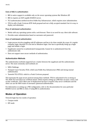
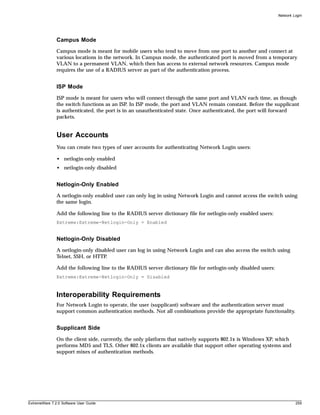
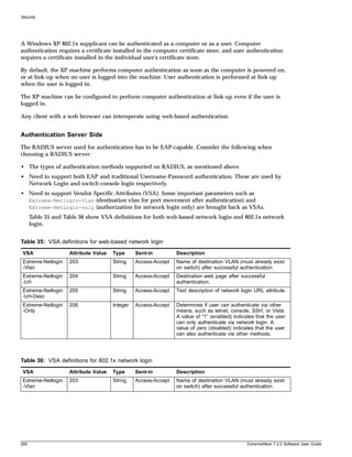
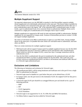
![Security
enable netlogin [web-based | dot1x]
disable netlogin [web-based |dot1x]
By default netlogin is enabled.
To show all network login parameters, use the following command:
show netlogin
Switch Protection
Switch protection features enhance the robustness of switch performance. In this category are the
following features:
• Routing Access Profiles
• Route Maps
• Denial of Service Protection
Routing Access Profiles
Routing access profiles are used to control the advertisement or recognition of routing protocols, such as
RIP, OSPF, IS-IS, or BGP. Routing access profiles can be used to ‘hide’ entire networks, or to trust only
specific sources for routes or ranges of routes. The capabilities of routing access profiles are specific to
the type of routing protocol involved, but are sometimes more efficient and easier to implement than
access lists.
Using Routing Access Profiles
To use routing access profiles, you must perform the following steps:
1 Create an access profile.
2 Configure the access profile to be of type permit, deny, or none.
3 Add entries to the access profile. Entries can be one of the following types:
— IP addresses and subnet masks
— IPX node, IPX RIP, and IPX SAP
— Autonomous system path expressions (as-paths) (BGP only)
— BGP communities (BGP only)
— VLAN
4 Apply the access profile.
Creating an Access Profile
The first thing to do when using routing access profiles is to create an access profile. An access profile has
a unique name and contains one of the following entry types:
• A list of IP addresses and associated subnet masks
266 ExtremeWare 7.2.0 Software User Guide](https://image.slidesharecdn.com/extremewareuserguide72-110124002726-phpapp01/85/Extreme-wareuserguide72-266-320.jpg)
![Using Routing Access Profiles
• A list of IPX NetIDs
• A list of IPX node addresses
• A list of IPX SAP advertisements
• One or more autonomous system path expressions (BGP only)
• One or more BGP community numbers (BGP only)
• A VLAN
You must give the access profile a unique name (in the same manner as naming a VLAN, protocol filter,
or Spanning Tree Domain). To create an access profile, use the following command:
create access-profile <access profile> type [ipaddress | ipx-node | ipx-net | ipx-sap
| as-path | bgp-community | vlan]
Configuring an Access Profile Mode
After the access profile is created, you must configure the access profile mode. The access profile mode
determines whether the items in the list are to be permitted access or denied access.
Three modes are available:
• Permit—The permit access profile mode permits the operation, as long as it matches any entry in the
access profile. If the operation does not match any entries in the list, the operation is denied.
• Deny—The deny access profile mode denies the operation, as long as it matches any entry in the
access profile. If it does not match all specified entries in the list, the operation is permitted.
• None—Using the none mode, the access profile can contain a combination of permit and deny
entries. Each entry must have a permit or deny attribute. The operation is compared with each entry
in the list. Once a match is found, the operation is either permitted or denied, depending on the
configuration of the matched entry. If no match is found, the operation is implicitly denied.
To configure the access profile mode, use the following command:
configure access-profile <access profile> mode [permit | deny | none]
Adding an Access Profile Entry
Next, configure the access profile, using the following command:
configure access-profile <access profile> add {<seq_number>} {permit | deny}
[ipaddress <ip address> <mask> {exact} | as-path <path-expression> | bgp-community
[internet | no-export | no-advertise | no-export-subconfed | <as_no:number> | number
<community>] | ipxnet <netid> <netid mask> | ipxsap <sap_type> <service_name> | vlan]
The following sections describe the configure access-profile add command.
Specifying Subnet Masks
The subnet mask specified in the access profile command is interpreted as a reverse mask. A reverse
mask indicates the bits that are significant in the IP address. In other words, a reverse mask specifies the
part of the address that must match the IP address to which the profile is applied.
ExtremeWare 7.2.0 Software User Guide 267](https://image.slidesharecdn.com/extremewareuserguide72-110124002726-phpapp01/85/Extreme-wareuserguide72-267-320.jpg)
![Security
If you configure an IP address that is an exact match that is specifically denied or permitted, use a mask
of /32 (for example, 141.251.24.28/32). If the IP address represents all addresses in a subnet address that
you want to deny or permit, then configure the mask to cover only the subnet portion (for example,
141.251.10.0/24). The keyword exact can be used when you wish to match only against the subnet
address, and ignore all addresses within the subnet.
If you are using off-byte boundary subnet masking, the same logic applies, but the configuration is
more tricky. For example, the network address 141.251.24.128/27 represents any host from subnet
141.251.24.128.
Sequence Numbering
You can specify the sequence number for each access profile entry. If you do not specify a sequence
number, entries are sequenced in the order they are added. Each entry is assigned a value of 5 more
than the sequence number of the last entry.
Permit and Deny Entries
If you have configured the access profile mode to be none, you must specify each entry type as either
‘permit’ or ‘deny’. If you do not specify the entry type, it is added as a permit entry. If you have
configured the access profile mode to be permit or deny, it is not necessary to specify a type for each
entry.
IPX Access Profiles
IPX routing access profiles consist of access rules and are used to perform packet filtering and
forwarding decisions on incoming traffic. Each IPX RIP or SAP packet arriving on an ingress port is
compared to each access profile rule in sequential order and is either forwarded or dropped.
Autonomous System Expressions
The AS-path keyword uses a regular expression string to match against the AS path. Regular expression
notation can include any of the characters listed in Table 37.
Table 37: Regular Expression Notation
Character Definition
N As number
N1 - N2 Range of AS numbers, where N1 and N2 are AS numbers and N1 < N2
[Nx ... Ny] Group of AS numbers, where Nx and N y are AS numbers or a range of AS numbers
[^Nx ... Ny] Any AS numbers other than the ones in the group
. Matches any number
^ Matches the beginning of the AS path
$ Matches the end of the AS path
– Matches the beginning or end, or a space
- Separates the beginning and end of a range of numbers
* Matches 0 or more instances
+ Matches 1 or more instances
? Matches 0 or 1 instance
{ Start of AS SET segment in the AS path
268 ExtremeWare 7.2.0 Software User Guide](https://image.slidesharecdn.com/extremewareuserguide72-110124002726-phpapp01/85/Extreme-wareuserguide72-268-320.jpg)
![Using Routing Access Profiles
Table 37: Regular Expression Notation (Continued)
Character Definition
} End of AS SET segment in the AS path
( Start of a confederation segment in the AS path
) End of a confederation segment in the AS path
Autonomous System Expression Example
The following example uses combinations of the autonomous system expressions to create a
complicated access profile:
create access-profile AS1 type as-path
configure access-profile AS1 mode none
These commands create the access profile.
configure access-profile AS1 add 5 permit as-path “^65535$”
This command configures the access profile to permit AS paths that contain only (begin and end with)
AS number 65535.
configure access-profile AS1 add 10 permit as-path “^65535 14490$”
This command configures the access profile to permit AS paths beginning with AS number 65535,
ending with AS number 14490, and containing no other AS paths.
configure access-profile AS1 add 15 permit as-path “^1 2-8 [11 13 15]$”
This command configures the access profile to permit AS paths beginning with AS number 1, followed
by any AS number from 2 - 8, and ending with either AS number 11, 13, or 15.
configure access-profile AS1 add 20 deny as-path “111 [2-8]”
This command configures the access profile to deny AS paths beginning with AS number 111 and
ending with any AS number from 2 - 8.
configure access-profile AS1 add 25 permit as-path “111 .?”
This command configures the access profile to permit AS paths beginning with AS number 111 and
ending with any additional AS number, or beginning and ending with AS number 111.
Deleting an Access Profile Entry
To delete an access profile entry, use the following command:
configure access-profile <access profile> delete <seq_number>
Applying Access Profiles
Once the access profile is defined, apply it to one or more routing protocols or VLANs. When an access
profile is applied to a protocol function (for example, the export of RIP routes) or a VLAN, this forms an
access policy. A profile can be used by multiple routing protocol functions or VLANs, but a protocol
function or VLAN can use only one access profile.
ExtremeWare 7.2.0 Software User Guide 269](https://image.slidesharecdn.com/extremewareuserguide72-110124002726-phpapp01/85/Extreme-wareuserguide72-269-320.jpg)
![Security
Routing Profiles for RIP
If you are using the RIP protocol, the switch can be configured to use an access profile to determine:
• Trusted Neighbor—Use an access profile to determine trusted RIP router neighbors for the VLAN
on the switch running RIP. To configure a trusted neighbor policy, use the following command:
configure rip vlan [<vlan name> | all] trusted-gateway [<access profile> | none]
• Import Filter—Use an access profile to determine which RIP routes are accepted as valid routes. This
policy can be combined with the trusted neighbor policy to accept selected routes only from a set of
trusted neighbors. To configure an import filter policy, use the following command:
configure rip vlan [<vlan name> | all] import-filter [<access profile> | none]
• Export Filter—Use an access profile to determine which RIP routes are advertised into a particular
VLAN, using the following command:
configure rip vlan [<vlan name> | all] export-filter [<access profile> | none]
Examples
In the example shown in Figure 35, a switch is configured with two VLANs, Engsvrs and Backbone. The
RIP protocol is used to communicate with other routers on the network. The administrator wants to
allow all internal access to the VLANs on the switch, but no access to the router that connects to the
Internet. The remote router that connects to the Internet has a local interface connected to the corporate
backbone. The IP address of the local interface connected to the corporate backbone is 10.0.0.10/24.
Figure 35: RIP access policy example
Internet
Internet
10.0.0.10 / 24
Backbone (RIP)
10.0.0.11 / 24 10.0.0.12 / 24
Switch being Engsvrs Sales
configured
10.1.1.1 / 24 10.2.1.1 / 24
Engsvrs Sales
EW_001
270 ExtremeWare 7.2.0 Software User Guide](https://image.slidesharecdn.com/extremewareuserguide72-110124002726-phpapp01/85/Extreme-wareuserguide72-270-320.jpg)
![Using Routing Access Profiles
Assuming the backbone VLAN interconnects all the routers in the company (and, therefore, the Internet
router does not have the best routes for other local subnets), the commands to build the access policy
for the switch would be:
create access-profile nointernet ipaddress
configure access-profile nointernet mode deny
configure access-profile nointernet add 10.0.0.10/32
configure rip vlan backbone trusted-gateway nointernet
In addition, if the administrator wants to restrict any user belonging to the VLAN Engsvrs from
reaching the VLAN Sales (IP address 10.2.1.0/24), the additional access policy commands to build the
access policy would be:
create access-profile nosales ipaddress
configure access-profile nosales mode deny
configure access-profile nosales add 10.2.1.0/24
configure rip vlan backbone import-filter nosales
This configuration results in the switch having no route back to the VLAN Sales.
Routing Access Profiles for IPX
If you are using the IPX protocol, the switch can be configured to use an access profile to determine:
• Import Filter—Use an access profile to determine which IPX/RIP or IPX/SAP routes are accepted as
valid routes. To configure an import filter policy, use the following command:
configure ipxrip vlan [<vlan name> | all] import-filter [none | <access_profile>]
configure ipxsap vlan [<vlan name> | all] import-filter [none | access_profile]]
• Export Filter—Use an access profile to determine which IPX/RIP and IPX/SAP routes are advertised
into a particular VLAN, using the following command:
configure ipxrip vlan [<vlan name> | all] export-filter [none | <access_profile>]
configure ipxsap vlan [<vlan name> | all] export-filter [none | access_profile]
Routing Access Profiles for OSPF
Because OSPF is a link-state protocol, the access profiles associated with OSPF are different in nature
than those associated with RIP. Access profiles for OSPF are intended to extend the existing filtering and
security capabilities of OSPF (for example, link authentication and the use of IP address ranges). If you
are using the OSPF protocol, the switch can be configured to use an access profile to determine any of
the following:
• Inter-area Filter—For switches configured to support multiple OSPF areas (an ABR function), an
access profile can be applied to an OSPF area that filters a set of OSPF inter-area routes from being
sourced from any other areas. To configure an inter-area filter policy, use the following command:
configure ospf area <area identifier> interarea-filter [<access profile> | none]
• External Filter—For switches configured to support multiple OSPF areas (an ABR function), an
access profile can be applied to an OSPF area that filters a set of OSPF external routes from being
advertised into that area. To configure an external filter policy, use the following command:
configure ospf area <area identifier> external-filter [<access profile> |none]
ExtremeWare 7.2.0 Software User Guide 271](https://image.slidesharecdn.com/extremewareuserguide72-110124002726-phpapp01/85/Extreme-wareuserguide72-271-320.jpg)
![Security
NOTE
If any of the external routes specified in the filter have already been advertised, those routes will remain
until the associated LSAs in that area time-out.
• ASBR Filter—For switches configured to support RIP and static route re-distribution into OSPF, an
access profile can be used to limit the routes that are advertised into OSPF for the switch as a whole.
To configure an ASBR filter policy, use the following command:
configure ospf asbr-filter [<access profile> | none]
• Direct Filter—For switches configured to support direct route re-distribution into OSPF, an access
profile can be used to limit the routes that are advertised into OSPF for the switch as a whole. To
configure a direct filter policy, use the following command:
configure ospf direct-filter [<access profile> | none]
272 ExtremeWare 7.2.0 Software User Guide](https://image.slidesharecdn.com/extremewareuserguide72-110124002726-phpapp01/85/Extreme-wareuserguide72-272-320.jpg)
![Using Routing Access Profiles
Example
Figure 36 illustrates an OSPF network that is similar to the network used previously in the RIP example.
In this example, access to the Internet is accomplished by using the ASBR function on the switch labeled
Internet. As a result, all routes to the Internet will be done through external routes. Suppose the
network administrator wishes to only allow access to certain internet addresses falling within the range
192.1.1.0/24 to the internal backbone.
Figure 36: OSPF access policy example
Internet
Switch being Internet
configured
10.0.0.10 / 24
Backbone (OSPF)
area 0.0.0.0
10.0.0.11 / 24 10.0.0.12 / 24
Engsvrs Sales
10.1.1.1 / 24 10.2.1.1 / 24
Engsvrs Sales
area 0.0.0.1 area 0.0.0.2
EW_002
To configure the switch labeled Internet, the commands would be as follows:
create access-profile okinternet ipaddress
configure access-profile okinternet mode permit
configure access-profile okinternet add 192.1.1.0/24
configure ospf asbr-filter okinternet
Routing Access Profiles for DVMRP
The access policy capabilities for DVMRP are very similar to those for RIP. If you are using the DVMRP
protocol is used for routing IP multicast traffic, you can configure the switch to use an access profile to
determine:
• Trusted Neighbor—Use an access profile to determine trusted DVMRP router neighbors for the
VLAN on the switch running DVMRP. To configure a trusted neighbor policy, use the following
command:
configure dvmrp vlan [<vlan name> | all] trusted-gateway [<access profile> |
none]
ExtremeWare 7.2.0 Software User Guide 273](https://image.slidesharecdn.com/extremewareuserguide72-110124002726-phpapp01/85/Extreme-wareuserguide72-273-320.jpg)
![Security
• Import Filter—Use an access profile to determine which DVMRP routes are accepted as valid routes.
To configure an import filter policy, use the following command:
configure dvmrp vlan [<vlan name> | all] import-filter [<access profile> | none]
• Export Filter—Use an access profile to determine which DVMRP routes are advertised into a
particular VLAN, using the following command:
configure dvmrp vlan [<vlan name> | all] export-filter [<access profile> | none]
Example
In this example, the network used in the previous RIP example is configured to run DVMRP. The
network administrator wants to disallow Internet access for multicast traffic to users on the VLAN
Engsvrs. This is accomplished by preventing the learning of routes that originate from the switch labeled
Internet by way of DVMRP on the switch labeled Engsvrs.
To configure the switch labeled Engsvrs, use the following commands:
create access-profile nointernet ipaddress
configure access-profile nointernet mode deny
configure access-profile nointernet add 10.0.0.10/32
configure dvmrp vlan backbone trusted-gateway nointernet
In addition, suppose the administrator wants to preclude users on the VLAN Engsvrs from seeing any
multicast streams that are generated by the VLAN Sales across the backbone. The additional
configuration of the switch labeled Engsvrs is as follows:
create access-profile nosales ipaddress
configure access-profile nosales mode deny
configure access-profile nosales add 10.2.1.0/24
configure dvmrp vlan backbone import-filter nosales
Routing Access Profiles for PIM
Because PIM leverages the unicast routing capability that is already present in the switch, the access
policy capabilities are, by nature, different. If you are using the PIM protocol for routing IP multicast
traffic, you can configure the switch to use an access profile to determine:
• Trusted Neighbor—Use an access profile to determine trusted PIM router neighbors for the VLAN
on the switch running PIM. To configure a trusted neighbor policy, use the following command:
configure pim vlan [<vlan name> | all] trusted-gateway [<access profile> | none]
Example
Using PIM, the unicast access profiles can be used to restrict multicast traffic. In this example, a network
similar to the example used in the previous RIP example is also running PIM. The network
administrator wants to disallow Internet access for multicast traffic to users on the VLAN Engsvrs. This
is accomplished by preventing the learning of routes that originate from the switch labeled Internet by
way of PIM on the switch labeled Engsvrs.
274 ExtremeWare 7.2.0 Software User Guide](https://image.slidesharecdn.com/extremewareuserguide72-110124002726-phpapp01/85/Extreme-wareuserguide72-274-320.jpg)
![Making Changes to a Routing Access Policy
To configure the switch labeled Engsvrs, the commands would be as follows:
create access-profile nointernet ipaddress
configure access-profile nointernet mode deny
configure access-profile nointernet add 10.0.0.10/32
configure pim vlan backbone trusted-gateway nointernet
Routing Access Profiles for BGP
If the BGP protocol is being used, the switch can be configured to use an access profile to determine:
• NLRI filter—Use an access profile to determine the NLRI information that must be exchanged with
a neighbor. To configure an NLRI filter policy, use the following command:
configure bgp neighbor [<ipaddress> | all] nlri-filter [in | out]
[<access_profile> | none]
The NLRI filter access policy can be applied to the ingress or egress updates, using the in and out
keywords, respectively.
• Autonomous system path filter—Use an access profile to determine which NLRI information must
be exchanged with a neighbor based on the AS path information present in the path attributes of the
NLRI. To configure an autonomous system path filter policy, use the following command:
configure bgp neighbor [<ipaddress> | all] as-path-filter [in | out]
[<access_profile> | none]
The autonomous system path filter can be applied to the ingress or egress updates, using the in and
out keywords, respectively.
Making Changes to a Routing Access Policy
You can change the routing access policy by changing the associated access profile. However, the
propagation of the change depends on the protocol and policy involved. Propagation of changes
applied to RIP, DVMRP, and PIM access profiles depend on the respective protocol timers to age-out
entries.
In BGP, the change to the policy is immediately effective on the routing information exchanged after the
policy changes. The changes can be applied on the routing information that had been exchanged before
the policy changes by issuing a soft reset on the ingress or egress side, depending on the change. For
soft resets to be applied on the ingress side, the changes must have been previously enabled on the
neighbor.
NOTE
Changes to profiles applied to OSPF typically require rebooting the switch, or disabling and re-enabling
OSPF on the switch.
ExtremeWare 7.2.0 Software User Guide 275](https://image.slidesharecdn.com/extremewareuserguide72-110124002726-phpapp01/85/Extreme-wareuserguide72-275-320.jpg)
![Security
Removing a Routing Access Policy
To remove a routing access policy, you must remove the access profile from the routing protocol or
VLAN. All the commands that apply an access profile to form an access policy also have the option of
choosing none as the access profile. Using the none option removes any access profile of that particular
type from the protocol or VLAN, and, therefore, removes the access policy.
Route Maps
Route maps are used to modify or filter routes. They are also used to modify or filter routing
information.
Using Route Maps
Route maps are a mechanism that can be used to conditionally control the redistribution of routes
between two routing domains, and to modify the routing information that is redistributed.
Route maps are used in conjunction with the match and set operations. A match operation specifies a
criteria that must be matched. A set operation specifies a change that is made to the route when the
match operation is successful.
To create a route map, follow these steps:
1 Create a route map.
2 Add entries to the route map.
3 Add statements to the route map entries.
Creating a Route Map
To create a route map, use the following command:
create route-map <name>
Add Entries to the Route Map
To add entries to the route map, use the following command:
configure route-map <route-map> add <seq_number> [permit | deny] {match-one |
match-all} {set lpm-routing | set iphost-routing}
where the following is true:
• The sequence number uniquely identifies the entry, and determines the position of the entry in the
route map. Route maps are evaluated sequentially.
• The permit keyword permits the route; the deny keyword denies the route and is applied only if the
entry is successful.
• The match-one keyword is a logical “or”. The route map is successful as long as at least one of the
matching statements is true.
276 ExtremeWare 7.2.0 Software User Guide](https://image.slidesharecdn.com/extremewareuserguide72-110124002726-phpapp01/85/Extreme-wareuserguide72-276-320.jpg)
![Using Route Maps
• The match-all keyword is a logical “and”. The route map is successful when all match statements
are true. This is the default setting.
Add Statements to the Route Map Entries
To add statements to the route map entries, use one of the following four commands:
configure route-map <route-map> <seq_number> add match [nlri-list <access profile> |
as-path [access-profile <access profile> | <as_number>] | community [access-profile
<access profile> | <as_number>:<number> | number <community> | no-advertise |
no-export | no-export-subconfed] | next-hop <ip address> | med <number> | tag <number>
| origin [igp | egp | incomplete]]]
configure route-map <route-map> <seq_number> add set [as-path <as_number> | community
[[access-profile <access-profile> | <as_number>:<number> | number <community> |
no-advertise | no-export | no-export-subconfed] | remove | [add | delete]
[access-profile <access-profile> | <as no> : <number> | number <community> |
no-advertise | no-export | no-export-subconfed]] | next-hop <ip address> | med
[internal | <med_number> | remove | [add | delete] <med_number>] local-preference
<number> | weight <number> | origin [igp | egp | incomplete] | tag <tag_number> |
accounting index <index_number> value <value_number> | cost <number> | cost-type
[ase-type-1 | ase-type-2]]]
configure route-map <route_map> <seq_number> add goto <new_route_map>
configure route-map <route-map> add <seq_number> [permit | deny] {match-one |
match-all} {set lpm-routing | set iphost-routing}
where the following is true:
• The route-map is the name of the route map.
• The sequence number identifies the entry in the route map to which this statement is being added.
• The match, set, and goto keywords specify the operations to be performed. Within a entry, the
statements are sequenced in the order of their operation. The match statements are first, followed by
set, and then goto.
• The nlri-list, as-path, community, next-hop, med, origin, and weight keywords specify the type
of values that must be applied using the specified operation against the corresponding attributes as
described in Table 38 and Table 39.
• The accounting-index keyword specifies the bin number assigned to a specific route map as
discussed in Table 40.
Table 38: Match Operation Keywords
Keyword Description
nlri-list <access_profile> Matches the NLRI against the specified access profile.
as-path [<access_profile> | <as-no>] Matches the AS path in the path attributes against the specified access
profile or AS number.
community [access-profile Matches the communities in the path attribute against the specified BGP
<access-profile> | <as no>: <number> community access profile or the community number.
| number <community> | no-advertise |
no-export | no-export-subconfed]
ExtremeWare 7.2.0 Software User Guide 277](https://image.slidesharecdn.com/extremewareuserguide72-110124002726-phpapp01/85/Extreme-wareuserguide72-277-320.jpg)
![Security
Table 38: Match Operation Keywords (Continued)
Keyword Description
next-hop <ipaddress> Matches the next hop in the path attribute against the specified IP
address.
med <number> Matches the MED in the path attribute against the specified MED number.
origin [igp | egp | incomplete] Matches the origin in the path attribute against the specified origin.
tag <number> Matches the tag associated with the redistributed OSPF route.
Table 39: Set Operation Keywords
Keyword Definition
as-path <as no> Prepends the specified AS number to the AS path in the path attribute.
community [[access-profile Adds the specified community to the existing community in the path
<access-profile> | <as no>: <number> attribute.
| number <community> | no-advertise |
no-export | no-export-subconfed] |
remove | [add | delete] [access-profile
<access-profile> | <as no>: <number>
| number <community> | no-advertise |
no-export | no-export-subconfed]]
next-hop <ipaddress> Sets the next hop in the path attribute to the specified IP address.
med [internal | <number> | remove | Modifies the MED in the path attribute as specified:
[add | delete] <number>]
• internal—When used in the BGP neighbor output route map, the
MED attribute is set to a value equal to the metric to reach the
nexthop.
• <number>—Sets the MED attribute to the specified value.
• remove—Removes the MED attribute, if present.
• [add | delete] <number>—Adds or deletes the specified value to or
from the MED that is received. The final result is bound by 0 and
2147483647.
local-preference <number> Sets the local preference in the path attribute to the specified local
preference number.
weight <number> Sets the weight associated with the NLRI to the specified number.
origin [igp | egp | incomplete] Sets the origin in the path attributes to the specified origin.
tag <number> Sets the tag in the route to the specified number.
cost <number> Sets the cost of the route to the specified number
cost-type <number> Sets the type of the cost associated with the route.
accounting index [ase-type-1 | Sets the specified accounting index to the specified number.
ase-type-2]
Table 40: Set Operation Keywords
Command Description of Change
accounting-index <index> value Sets the accounting bin number for the route-mapped accounting index.
<value> The accounting index value is always set to 1 for Destination Sensitive
Accounting.
278 ExtremeWare 7.2.0 Software User Guide](https://image.slidesharecdn.com/extremewareuserguide72-110124002726-phpapp01/85/Extreme-wareuserguide72-278-320.jpg)
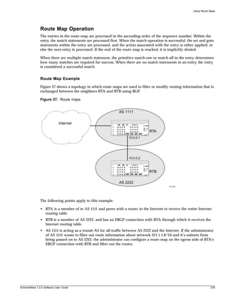
![Denial of Service Protection
Denial of Service Protection
A Denial-of-Service (DoS) attack occurs when a critical network or computing resource is overwhelmed
and rendered inoperative in a way that legitimate requests for service cannot succeed. In its simplest
form, a Denial of Service attack is indistinguishable from normal heavy traffic. Extreme Network
switches are not vulnerable to this simple attack because they are all designed to process packets in
hardware at wire speed. However, there are some operations in any switch or router that are more
costly than others, and although normal traffic is not a problem, exception traffic must be handled by
the switch’s CPU in software.
Some packets that the switch processes in the CPU software include:
• learning new traffic
• routing and control protocols including ICMP, BGP and OSPF
• switch management traffic (switch access by Telnet, SSH, HTTP, SNMP, etc...)
• other packets directed to the switch that must be discarded by the CPU
If any one of these functions is overwhelmed, the CPU may be too busy to service other functions and
switch performance will suffer. Even with very fast CPUs, there will always be ways to overwhelm the
CPU by with packets requiring costly processing.
DoS Protection is designed to help prevent this degraded performance by attempting to characterize the
problem and filter out the offending traffic so that other functions can continue. When a flood of
packets is received from the switch, DoS Protection will count these packets. When the packet count
nears the alert threshold, packets headers will be saved. If the threshold is reached, then these headers
are analyzed, and a hardware access control list (ACL) is created to limit the flow of these packets to the
CPU. This ACL will remain in place to provide relief to the CPU. Periodically, the ACL will expire, and
if the attack is still occurring, it will be re-enabled. With the ACL in place, the CPU will have the cycles
to process legitimate traffic and continue other services.
NOTE
DoS Protection can create an ACL at any one time for only one specific source. Only one ACL can be
active at any time, so when the switch is suffering an attack from multiple hosts, the CPU will still get
flooded.
Configuring Denial of Service Protection
To configure denial of service protection, use the following command:
configure cpu-dos-protect [alert-threshold <packets per second>] [notice-threshold
<packets per second>] [timeout <seconds>] [messages [on | off]] [filter-precedence
<number>] [filter-type-allowed {destination | source | destination source} {protocol}]
The default values for the parameters are as follows:
• alert-threshold—4000 packets per second
• notice-threshold—4000 packets per second
• timeout—15 seconds
• messages—on (messages are sent to syslog)
• filter-precedence—10
ExtremeWare 7.2.0 Software User Guide 281](https://image.slidesharecdn.com/extremewareuserguide72-110124002726-phpapp01/85/Extreme-wareuserguide72-281-320.jpg)
![Denial of Service Protection
• configuration or image upload/download
To configure the notice threshold, use the following command:
configure cpu-dos-protect notice-threshold <packets per second>
Next, configure the alert threshold. If the alert threshold is reached, a simulated ACL is put in place.
Although packets will not be dropped, this provides good information about the heavy traffic, which
might be legitimate or might be an attack. The Ethernet address of the source and the type of traffic can
be characterized by the type of ACL put in place. This is another way to judge if legitimate traffic
would have been cut off. To configure the alert threshold, use the following command:
configure cpu-dos-protect alert-threshold <packets per second>
After normal traffic is characterized, steps should be taken to set:
• the appropriate notice level if some warning is desired
• the appropriate alert level at which an ACL is put in place
• trusted ports from which traffic won’t be blocked
In some cases, traffic from a switch port or group of ports will never cause an attack. These ports can be
configured as trusted port and will never be considered for traffic that will generate an ACL. This can
prevent innocent hosts from being blocked, or ensure that when an innocent host responds to an attack
that the flood of response packets is not mistaken for the attack. To configure a trusted port, use the
following command:
configure cpu-dos-protect trusted-ports [add <port number> | delete <port number> |
all | none]
The last step is to enable DoS Protection. At this point, only attack traffic should be blocked and
legitimate traffic should pass through. To enable the creation of ACLs for DoS Protection, use the
following command:
enable cpu-dos-protect
Blocking SQL Slammer DoS Attacks
You can block the SQL Slammer DoS attack. SQL Slammer causes high CPU utilization on the next-hop
switch serving multicast requests as ICMP sender entries are quickly populated into the multicast
sender list. This leads to a high number of multicast entries in the IGMP snooping entry table, and a
message similar to the following in the system log:
<WARN:HW> tBGTask: Reached maximum otp ExtraMC index allocation
To block and clean up after this task:
1 Block the attack by creating an ACL to block port 1434 using the following command:
create access-list UDP dest any ip-port 1434 source any ip-port any
2 Remove affected SQL servers from the network
You can simply disable the port connecting the server.
3 Clean up the existing IGMP snooping entries and IPMC cache using the following commands:
igmp snooping
clear ipmc cache
ExtremeWare 7.2.0 Software User Guide 283](https://image.slidesharecdn.com/extremewareuserguide72-110124002726-phpapp01/85/Extreme-wareuserguide72-283-320.jpg)
![Security
4 Disable IGMP snooping on the affected switches.
Disabling IGMP snooping affects routing protocols using multicast addresses and multicast traffic on
that switch.
Management Access Security
Management access security features control access to the management functions available on the
switch. These features help insure that any configuration changes to the switch can only be done by
authorized users. In this category are the following features:
• Authenticating Users Using RADIUS or TACACS+
• Secure Shell 2 (SSH2)
Authenticating Users Using RADIUS or TACACS+
ExtremeWare provides two methods to authenticate users who login to the switch:
• RADIUS client
• TACACS+
RADIUS Client
Remote Authentication Dial In User Service (RADIUS, RFC 2138) is a mechanism for authenticating and
centrally administrating access to network nodes. The ExtremeWare RADIUS client implementation
allows authentication for Telnet, Vista, or console access to the switch.
NOTE
You cannot configure RADIUS and TACACS+ at the same time.
You can define a primary and secondary RADIUS server for the switch to contact. When a user
attempts to login using Telnet, http, or the console, the request is relayed to the primary RADIUS server,
and then to the secondary RADIUS server, if the primary does not respond. If the RADIUS client is
enabled, but access to the RADIUS primary and secondary server fails, the switch uses its local database
for authentication.
The privileges assigned to the user (admin versus nonadmin) at the RADIUS server take precedence
over the configuration in the local switch database.
To configure the RADIUS servers, use the following command:
configure radius [primary | secondary] server [<ipaddress> | <hostname>] {<udp_port>}
client-ip [<ipaddress>]
To configure the timeout if a server fails to respond, use the following command:
configure radius timeout <seconds>
284 ExtremeWare 7.2.0 Software User Guide](https://image.slidesharecdn.com/extremewareuserguide72-110124002726-phpapp01/85/Extreme-wareuserguide72-284-320.jpg)
![Authenticating Users Using RADIUS or TACACS+
Configuring the Shared Secret Password
In addition to specifying the RADIUS server IP information, RADIUS also contains a means to verify
communication between network devices and the server. The shared secret is a password configured on
the network device and RADIUS server, used by each to verify communication.
To configure the shared secret for RADIUS servers, use the following command:
configure radius [primary | secondary] shared-secret {encrypted} [<string>]
Enabling and Disabling RADIUS
After server information is entered, you can start and stop RADIUS authentication as many times as
necessary without needing to reconfigure server information.
To enable RADIUS authentication, use the following command:
enable radius
To disable RADIUS authentication, use the following command:
disable radius
Configuring RADIUS Accounting
Extreme switches are capable of sending RADIUS accounting information. As with RADIUS
authentication, you can specify two servers for receipt of accounting information. You can configure
RADIUS accounting servers to be the same as the authentication servers, but this is not required.
To specify RADIUS accounting servers, use the following command:
configure radius-accounting [primary | secondary] server [<ipaddress> | <hostname>]
{<udp_port>} client-ip [<ipaddress>]
To configure the timeout if a server fails to respond, use the following command:
configure radius-accounting timeout <seconds>
RADIUS accounting also makes use of the shared secret password mechanism to validate
communication between network access devices and RADIUS accounting servers.
To specify shared secret passwords for RADIUS accounting servers, use the following command:
configure radius-accounting [primary | secondary] shared-secret {encrypted} [<string>]
After you configure RADIUS accounting server information, you must enable accounting before the
switch begins transmitting the information. You must enable RADIUS authentication for accounting
information to be generated. You can enable and disable accounting without affecting the current state
of RADIUS authentication.
To enable RADIUS accounting, use the following command:
enable radius-accounting
To disable RADIUS accounting, use the following command:
disable radius-accounting
ExtremeWare 7.2.0 Software User Guide 285](https://image.slidesharecdn.com/extremewareuserguide72-110124002726-phpapp01/85/Extreme-wareuserguide72-285-320.jpg)
![Security
features. Source code for Extreme RADIUS can be obtained from the Extreme Networks Technical
Assistance Center and has been tested on Red Hat Linux and Solaris.
When Extreme RADIUS is up and running, the two most commonly changed files will be users and
profiles. The users file contains entries specifying login names and the profiles used for per-command
authentication after they have logged in. Sending a HUP signal to the RADIUS process is sufficient to
get changes in the users file to take place. Extreme RADIUS uses the file named profiles to specify
command lists that are either permitted or denied to a user based on their login identity. Changes to the
profiles file require the RADIUS server to be shutdown and restarted. Sending a HUP signal to the
RADIUS process is not enough to force changes to the profiles file to take effect.
When you create command profiles, you can use an asterisk to indicate any possible ending to any
particular command. The asterisk cannot be used as the beginning of a command. Reserved words for
commands are matched exactly to those in the profiles file. Due to the exact match, it is not enough to
simply enter “sh” for “show” in the profiles file, the complete word must be used. Commands can still
be entered in the switch in partial format.
When you use per-command authentication, you must ensure that communication between the
switch(es) and radius server(s) is not lost. If the RADIUS server crashes while users are logged in, they
will have full administrative access to the switch until they log out. Using two RADIUS servers and
enabling idle timeouts on all switches will greatly reduce the chance of a user gaining elevated access
due to RADIUS server problems.
RADIUS Server Configuration Example (Merit)
Many implementations of RADIUS server use the publicly available Merit© AAA server application,
available on the World Wide Web at:
http://www.merit.edu/aaa
Included below are excerpts from relevant portions of a sample Merit RADIUS server implementation.
The example shows excerpts from the client and user configuration files. The client configuration file
(ClientCfg.txt) defines the authorized source machine, source name, and access level. The user
configuration file (users) defines username, password, and service type information.
ClientCfg.txt
#Client Name Key [type] [version] [prefix]
#---------------- --------------- -------------- --------- --------
#10.1.2.3:256 test type = nas v2 pfx
#pm1 %^$%#*(&!(*&)+ type=nas pm1.
#pm2 :-):-(;^):-}! type nas pm2.
#merit.edu/homeless hmoemreilte.ses
#homeless testing type proxy v1
#xyz.merit.edu moretesting type=Ascend:NAS v1
#anyoldthing:1234 whoknows? type=NAS+RAD_RFC+ACCT_RFC
10.202.1.3 andrew-linux type=nas
10.203.1.41 eric type=nas
10.203.1.42 eric type=nas
10.0.52.14 samf type=nas
users
user Password = ""
Filter-Id = "unlim"
admin Password = "", Service-Type = Administrative
288 ExtremeWare 7.2.0 Software User Guide](https://image.slidesharecdn.com/extremewareuserguide72-110124002726-phpapp01/85/Extreme-wareuserguide72-288-320.jpg)
![Secure Shell 2 (SSH2)
You can configure two TACACS+ servers, specifying the primary server address, secondary server
address, and UDP port number to be used for TACACS+ sessions.
Secure Shell 2 (SSH2)
Secure Shell 2 (SSH2) is a feature of ExtremeWare that allows you to encrypt Telnet session data
between a network administrator using SSH2 client software and the switch, or to send encrypted data
from the switch to an SSH2 client on a remote system. Image and configuration files may also be
transferred to the switch using the Secure Copy Protocol 2 (SCP2). The ExtremeWare CLI provides a
command that enable the switch to function as an SSH2 client, sending commands to a remote system
via an SSH2 session. It also provides commands to copy image and configuration files to the switch
using the SCP2.
The ExtremeWare SSH2 switch application is based on the Data Fellows™ SSH2 server implementation.
It is highly recommended that you use the F-Secure SSH client products from Data Fellows
corporation. These applications are available for most operating systems. For more information, see the
Data Fellows website at:
http://www.datafellows.com.
NOTE
SSH2 is compatible with the Data Fellows SSH2 client version 2.0.12 or above. SSH2 is not compatible
with SSH1.
The ExtremeWare SSH2 switch application also works with SSH2 client and server (version 2.x or later)
from SSH Communication Security, and the free SSH2 and SCP2 implementation (version 2.5 or later)
from OpenSSH. The SFTP file transfer protocol is required for file transfer using SCP2.
Enabling SSH2 for Inbound Switch Access
Because SSH2 is currently under U.S. export restrictions, you must first obtain a security-enabled
version of the ExtremeWare software from Extreme Networks before you can enable SSH2. The
procedure for obtaining a security-enabled version of the ExtremeWare software is described in
Chapter 1.
You must enable SSH2 on the switch before you can connect to it using an external SSH2 client.
Enabling SSH2 involves two steps:
• Enabling SSH2 access, which may include specifying a list of clients that can access the switch, and
specifying a TCP port to be used for communication.
By default, if you have a security license, SSH2 is enabled using TCP port 22, with no restrictions on
client access.
• Generating or specifying an authentication key for the SSH2 session.
To enable SSH2, use the following command:
enable ssh2 {access-profile [<access profile> | none]} {port <tcp_port_number>}
You can specify a list of predefined clients that are allowed SSH2 access to the switch. To do this, you
must create an access profile that contains a list of allowed IP addresses.
ExtremeWare 7.2.0 Software User Guide 291](https://image.slidesharecdn.com/extremewareuserguide72-110124002726-phpapp01/85/Extreme-wareuserguide72-291-320.jpg)
![Security
You can also specify a TCP port number to be used for SSH2 communication. By default the TCP port
number is 22.
The supported ciphers are 3DES-CBC and Blowfish. The supported key exchange is DSA.
An authentication key must be generated before the switch can accept incoming SSH2 sessions. This can
be done automatically by the switch, or you can enter a previously generated key. To have the key
generated by the switch, use the following command:
configure ssh2 key
You are prompted to enter information to be used in generating the key. The key generation process
takes approximately ten minutes. Once the key has been generated, you should save your configuration
to preserve the key.
To use a key that has been previously created, use the following command:
configure ssh2 key {pregenerated}
You are prompted to enter the pregenerated key.
The key generation process generates the SSH2 private host key. The SSH2 public host key is derived
from the private host key, and is automatically transmitted to the SSH2 client at the beginning of an
SSH2 session.
Before you initiate a session from an SSH2 client, ensure that the client is configured for any nondefault
access list or TCP port information that you have configured on the switch. Once these tasks are
accomplished, you may establish an SSH2-encrypted session with the switch. Clients must have a valid
user name and password on the switch in order to log into the switch after the SSH2 session has been
established.
For additional information on the SSH protocol refer to [FIPS-186] Federal Information Processing
Standards Publication (FIPSPUB) 186, Digital Signature Standard, 18 May 1994. This can be download
from: ftp://ftp.cs.hut.fi/pub/ssh. General technical information is also available from:
http://www.ssh.fi
Using SCP2 from an External SSH2 Client
In ExtremeWare version 6.2.1 or later, the SCP2 protocol is supported for transferring image and
configuration files to the switch from the SSH2 client, and for copying the switch configuration from the
switch to an SSH2 client.
CAUTION
You can download a configuration to an Extreme Networks switch using SCP. If you do this, you cannot
save this configuration. If you save this configuration and reboot the switch, the configuration will be
corrupted.
The user must have administrator-level access to the switch. The switch can be specified by its switch
name or IP address.
Configuration or image files stored on the system running the SSH2 client may be named as desired by
the user. However, files on the switch have predefined names, as follows:
• configuration.cfg—The current configuration
292 ExtremeWare 7.2.0 Software User Guide](https://image.slidesharecdn.com/extremewareuserguide72-110124002726-phpapp01/85/Extreme-wareuserguide72-292-320.jpg)
![Secure Shell 2 (SSH2)
• incremental.cfg—The current incremental configuration
• primary.img—The primary ExtremeWare image
• secondary.img—The secondary ExtremeWare image
• bootrom.img—The BootROM image
For example, to copy an image file saved as image1.xtr to switch with IP address 10.10.0.5 as the primary
image using SCP2, you would enter the following command within your SSH2 session:
scp image1.xtr admin@10.20.0.5:primary.img
To copy the configuration from the switch and save it in file config1.save using SCP, you would enter the
following command within your SSH2 session:
scp admin@10.10.0.5:configuration.cfg config1.save
SSH2 Client Functions on the Switch
In ExtremeWare version 6.2.1 or later, an Extreme Networks switch can function as an SSH2 client. This
means you can connect from the switch to a remote device running an SSH2 server, and send
commands to that device. You can also use SCP2 to transfer files to and from the remote device.
You do not need to enable SSH2 or generate an authentication key to use the SSH2 and SCP2
commands from the ExtremeWare CLI.
To send commands to a remote system using SSH2, use the following command:
ssh2 {cipher [3des | blowfish]} {port <portnum>} {compression [on | off]} {user
<username>} {debug <debug_level>} {<username>@} [<host> | <ipaddress>] {<remote
command>}
The remote commands can be any commands acceptable by the remote system. You can specify the
login user name as a separate argument, or as part of the user@host specification. If the login user name
for the remote system is the same as your user name on the switch, you can omit the username
parameter entirely.
To initiate a file copy from a remote system to the switch using SCP2, use the following command:
scp2 {cipher [3des | blowfish]} {port <portnum>} {debug <debug_level>} <user>@
[<hostname> | <ipaddress>] :<remote_file> [configuration {incremental} | image
[primary | secondary] | bootrom]
To initiate a file copy to a remote system from the switch using SCP2, use the following command:
scp2 {cipher [3des | blowfish]} {port <portnum>} {debug <debug_level>} configuration
<user>@ [<hostname> | <ipaddress>]:<remote_file>
ExtremeWare 7.2.0 Software User Guide 293](https://image.slidesharecdn.com/extremewareuserguide72-110124002726-phpapp01/85/Extreme-wareuserguide72-293-320.jpg)


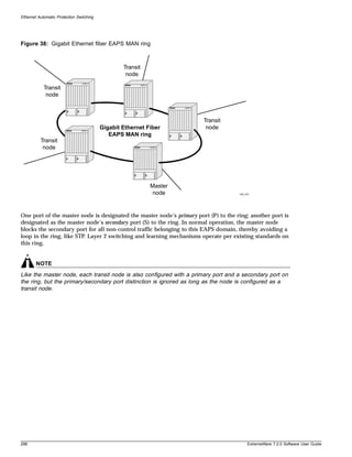
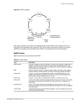
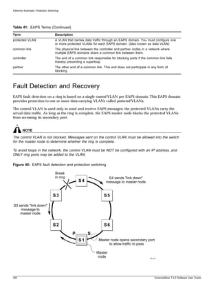
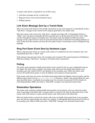
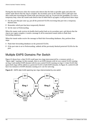
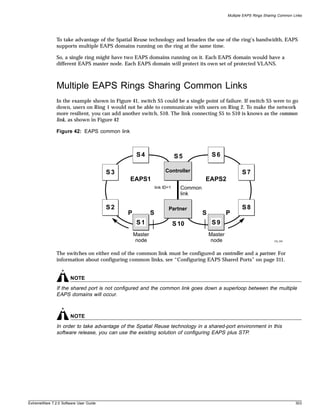
![Ethernet Automatic Protection Switching
Configuring EAPS on a Switch
This section describes how to configure EAPS on a switch.
Creating and Deleting an EAPS Domain
Each EAPS domain is identified by a unique domain name.
To create an EAPS domain, use the following command:
create eaps <name>
The name parameter is a character string of up to 32 characters that identifies the EAPS domain to be
created. EAPS domain names and VLAN names must be unique: Do not use the same name string to
identify both an EAPS domain and a VLAN.
The following command example creates an EAPS domain named “eaps_1”:
create eaps eaps_1
To delete an EAPS domain, use the following command:
delete eaps <name>
The following command example deletes the EAPS domain “eaps_1”:
delete eaps eaps_1
Defining the EAPS Mode of the Switch
To configure the EAPS node type of the switch, use the following command:
configure eaps <name> mode [master | transit]
One node on the ring must be configured as the master node for the specified domain; all other nodes
on the ring are configured as transit nodes for the same domain.
The following command example identifies this switch as the master node for the EAPS domain named
eaps_1.
configure eaps eaps_1 mode master
The following command example identifies this switch as a transit node for the EAPS domain named
eaps_1.
configure eaps eaps_1 mode transit
Configuring EAPS Polling Timers
To set the values of the polling timers the master node uses for the EAPS health-check packet that is
circulated around the ring for an EAPS domain, use the following command:
configure eaps <name> hellotime <seconds>
configure eaps <name> failtime [<seconds>]
304 ExtremeWare 7.2.0 Software User Guide](https://image.slidesharecdn.com/extremewareuserguide72-110124002726-phpapp01/85/Extreme-wareuserguide72-304-320.jpg)
![Configuring EAPS on a Switch
To configure the action taken if there is a break in the ring, use the following command:
configure eaps <name> failtime expiry-action [ open-secondary-port | send-alert]
NOTE
These commands apply only to the master node. If you configure the polling timers for a transit node,
they will be ignored. If you later reconfigure that transit node as the master node, the polling timer
values will be used as the current values.
Use the hellotime keyword and its associated seconds parameter to specify the amount of time the
master node waits between transmissions of health-check packets on the control VLAN. seconds must
be greater than 0 when you are configuring a master node. The default value is one second.
NOTE
Increasing the hellotime value keeps the processor from sending and processing too many
health-check packets. Increasing the hellotime value should not affect the network convergence time,
because transit nodes are already sending “link down” notifications.
Use the failtime keyword and seconds parameters to specify the amount of time the master node
waits before the failtimer expires.
The seconds parameter must be greater than the configured value for hellotime. The default value is
three seconds.
You can configure the action taken when the failtimer expires by using the configure eaps failtime
expiry-action command. Use the send-alert parameter to send an alert when the failtimer expires.
Instead of going into a “failed” state, the master node remains in a “Complete” or “Init” state, maintains
the secondary port blocking, and writes a critical error message to syslog warning the user that there is
a fault in the ring. An SNMP trap is also sent.
To use the failtimer expiry action of earlier releases, use the open-secondary-port parameter.
NOTE
Increasing the failtime value provides more protection by waiting longer to receive a health-check packet
when the network is congested.
The following command examples configure the hellotime value for the EAPS domain “eaps_1” to
2 seconds, the failtime value to 15 seconds, and the failtime expiry-action to open the secondary port if
the failtimer expires:
configure eaps eaps_1 hellotime 2
configure eaps eaps_1 failtime 15
configure eaps eaps_1 failtimer expiry-action open-secondary-port
ExtremeWare 7.2.0 Software User Guide 305](https://image.slidesharecdn.com/extremewareuserguide72-110124002726-phpapp01/85/Extreme-wareuserguide72-305-320.jpg)
![Ethernet Automatic Protection Switching
Configuring the Primary and Secondary Ports
Each node on the ring connects to the ring through two ring ports. As part of the protection switching
scheme, one port must be configured as the primary port; the other must be configured as the secondary
port.
If the ring is complete, the master node prevents a loop by logically blocking all data traffic in the
transmit and receive directions on its secondary port. If the master node subsequently detects a break in
the ring, it unblocks its secondary port and allows data traffic to be transmitted and received through it.
To configure a node port as primary or secondary, use the following command:
configure eaps <eaps domain> [primary | secondary] port <port number>
The following command example adds port 1 of the module installed in slot 8 of the BlackDiamond
switch to the EAPS domain “eaps_1” as the primary port.
configure eaps eaps_1 primary port 8:1
Configuring the EAPS Control VLAN
You must configure one control VLAN for each EAPS domain. The control VLAN is used only to send
and receive EAPS messages.
NOTE
A control VLAN cannot belong to more than one EAPS domain. If the domain is active, you cannot
delete the domain or modify the configuration of the control VLAN.
To configure the EAPS control VLAN for the domain, use the following command:
configure eaps <name> add control vlan <vlan_name>
NOTE
The control VLAN must NOT be configured with an IP address. In addition, only ring ports may be
added to this control VLAN. No other ports can be members of this VLAN. Failure to observe these
restrictions can result in a loop in the network.
NOTE
When you configure the VLAN that will act as the control VLAN, that VLAN must be assigned a QoS
profile of Qp8, and the ring ports of the control VLAN must be tagged.
By assigning the control VLAN a QoS profile of Qp8 (with the QoS profile HighHi priority setting), you
ensure that EAPS control VLAN traffic is serviced before any other traffic and that control VLAN
messages reach their intended destinations. For example, if the control VLAN is not assigned the
highest priority and a broadcast storm occurs in the network, the control VLAN messages might be
dropped at intermediate points. Assigning the control VLAN the highest priority prevents dropped
control VLAN messages.
Because the QoS profile HighHi priority setting by itself should ensure that the control VLAN traffic
gets through a congested port first, you should not need to set the QoS profile minimum bandwidth
306 ExtremeWare 7.2.0 Software User Guide](https://image.slidesharecdn.com/extremewareuserguide72-110124002726-phpapp01/85/Extreme-wareuserguide72-306-320.jpg)
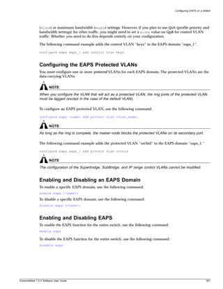
![Ethernet Automatic Protection Switching
Unconfiguring an EAPS Ring Port
Unconfiguring an EAPS port sets its internal configuration state to INVALID, which causes the port to
appear in the Idle state with a port status of Unknown when you use the show eaps {<name>}
{detail} command to display the status information about the port.
To unconfigure an EAPS primary or secondary ring port for an EAPS domain, use the following
command:
unconfigure eaps <name> [primary | secondary] port
The following command example unconfigures this node’s EAPS primary ring port on the domain
“eaps_1”:
unconfigure eaps eaps_1 primary port
Displaying EAPS Status Information
To display EAPS status information, use the following command:
show eaps summary
This example displays summary EAPS information on a transit node:
EAPS Enabled: Yes
Number of EAPS instances: 3
EAPSD-Bridge links: 6
Pri Sec Vlan
Domain State Mo En Port Port Control-Vlan (VID) count
------------ ------------ -- -- ------- ------- -----------------------
eaps4 Links-Up T Y 1:1 1:4 cv4 (1004) 1
eaps3 Links-Up T Y 1:1 1:3 cv3 (1003) 1
eaps2 Links-Up T Y 1:1 1:2 cv2 (1002) 1
EAPS shared-port count: 1
Link Domain Vlan RB RB
Shared-port Mode Id Up State count count Nbr State Id
----------- ---------- ---- -- --------- ------ ----- --- ------- -----
1:1 Controller 2 Y Ready 3 1 Yes None None
EAPS Domain list: "eaps2" "eaps3" "eaps4"
To display more detailed EAPS status information, use the following command:
show eaps {<name>} {detail}
If you enter the show eaps command without an argument or keyword, the command displays a
summary of status information for all configured EAPS domains. You can use the detail keyword to
display more detailed status information.
NOTE
The output displayed by this command depends on whether the node is a transit node or a master
node. The display for a transit node contains information fields that are not shown for a master node.
Also, some state values are different on a transit node than on a master node.
308 ExtremeWare 7.2.0 Software User Guide](https://image.slidesharecdn.com/extremewareuserguide72-110124002726-phpapp01/85/Extreme-wareuserguide72-308-320.jpg)
![Configuring EAPS on a Switch
The following example of the show eaps {<name>} {detail} command displays detailed EAPS
information for a transit node. Table 42 describes the fields and values in the display.
* Summit5iTx:39 # show eaps detail
EAPS Enabled: Yes
Number of EAPS instances: 1
EAPSD-Bridge links: 2
Name: “eaps1” (instance=0)
State: Links Up [Running: Yes]
Enabled: Yes Mode: Transit
Primary port: 13 Port status: Up Tag status: Tagged
Secondary port: 14 Port status: Up Tag status: Tagged
Hello Timer interval: 1 sec Fail Timer interval: 3 sec
Preforwarding Timer interval: 3 sec
Last update: From Master Id 00:01:30:B9:4B:E0, at Tue May 6 12:49:25 2003
Eaps Domain has following Controller Vlan:
Vlan Name VID QosProfile
“rhsc” 0020 QP8
EAPS Domain has following Protected Vlan(s):
Vlan Name VID
“traffic” 1001
Number of Protected Vlans: 1
The following example of the show eaps {<name>} {detail} command displays detailed EAPS
information for a single EAPS domain named “eaps2” on the master node. Table 42 describes significant
fields and values in the display.
* Baker15:4 # show eaps2 detail
Name: “eaps2” (instance=0)
State: Complete [Running: Yes]
Enabled: Yes Mode: Master
Primary port: 14 Port status: Up Tag status: Tagged
Secondary port: 13 Port status: Blocked Tag status: Tagged
Hello Timer interval: 1 sec Fail Timer interval: 3 sec
Failtimer expiry action: Send alert
Last update: From Master Id 00:01:30:B9:4B:E0, at Tue May 6 12:49:25 2003
Eaps Domain has following Controller Vlan:
Vlan Name VID QosProfile
“rhsc” 0020 QP8
EAPS Domain has following Protected Vlan(s):
Vlan Name VID
“blue” 1003
“traffic” 1001
Number of Protected Vlans: 2
Table 42: show eaps Display Fields
Field Description
EAPS Enabled: Current state of EAPS on this switch:
• Yes—EAPS is enabled on the switch.
• No—EAPS is not enabled.
EAPS Fast Convergence: Displays only when Fast Convergence is on.
Number of EAPS instances: Number of EAPS domains created. The maximum number of EAPS
domains per switch is 64.
ExtremeWare 7.2.0 Software User Guide 309](https://image.slidesharecdn.com/extremewareuserguide72-110124002726-phpapp01/85/Extreme-wareuserguide72-309-320.jpg)
![Ethernet Automatic Protection Switching
Table 42: show eaps Display Fields (Continued)
Field Description
EAPSD-Bridge links: The total number of EAPS bridge links in the system. The maximum
count is 4096. Each time a VLAN is added to EAPS, this count
increments by 1.
Name: The configured name for this EAPS domain.
(Instance= ) The instance number is created internally by the system.
State: On a transit node, the command displays one of the following states:
• Idle—The EAPS domain has been enabled, but the configuration is
not complete.
• Links-Up—This EAPS domain is running, and both its ports are up
and in the FORWARDING state.
• Links-Down—This EAPS domain is running, but one or both of its
ports are down.
• Preforwarding—This EAPS domain is running, and both of its ports
are up, but one of them is in a temporary BLOCKED state.
On a master node, the command displays one of the following states:
• Idle—The EAPS domain has been enabled, but the configuration is
not complete.
• Init—The EAPS domain has started but has not yet determined the
status of the ring. The secondary port is in a BLOCKED state.
• Complete—The ring is in the COMPLETE state for this EAPS
domain.
• Failed—There is a break in the ring for this EAPS domain.
• [Failtimer Expired]—When the failtimer expires and it’s action is set
to send-alert, this flag is set. This flag indicates there is a
misconfiguration or hardware problem in the EAPS ring. The EAPS
master node will continue to remain in COMPLETE or INIT state
with it’s secondary port blocking.
[Running: …] • Yes—This EAPS domain is running.
• No—This EAPS domain is not running.
Enabled: Indicates whether EAPS is enabled on this domain.
• Y—EAPS is enabled on this domain.
• N—EAPS is not enabled.
Mode: The configured EAPS mode for this switch: transit (T) or master (M).
Primary/Secondary port: The port numbers assigned as the EAPS primary and secondary ports.
On the master node, the port distinction indicates which port is blocked
to avoid a loop.
Port status: • Unknown—This EAPS domain is not running, so the port status has
not yet been determined.
• Up—The port is up and is forwarding data.
• Down—The port is down.
• Blocked—The port is up, but data is blocked from being forwarded.
310 ExtremeWare 7.2.0 Software User Guide](https://image.slidesharecdn.com/extremewareuserguide72-110124002726-phpapp01/85/Extreme-wareuserguide72-310-320.jpg)
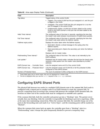
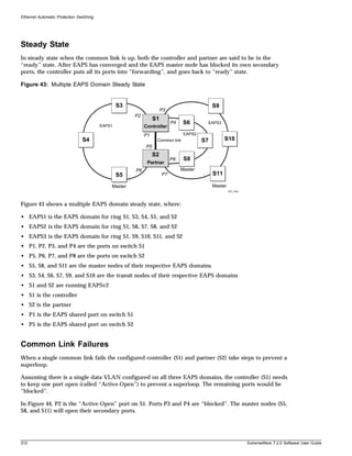
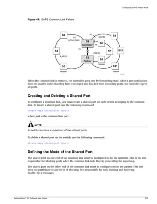
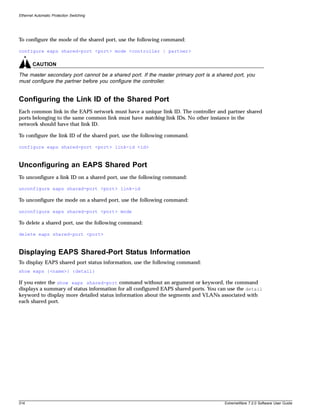
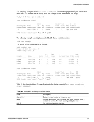
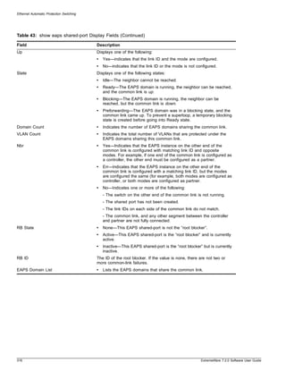
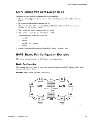
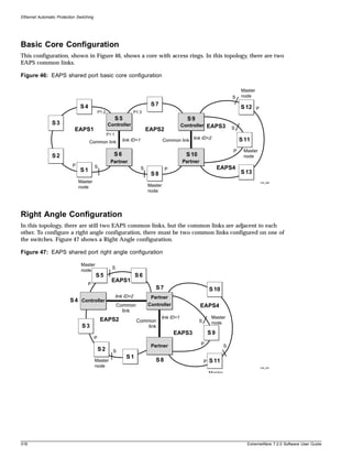
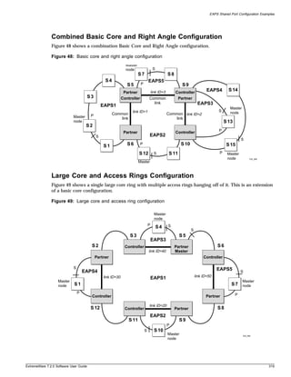
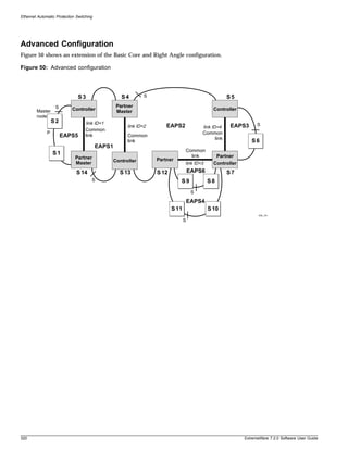
![Spanning Tree Protocol (STP)
Spanning Tree Domains
The switch can be partitioned into multiple virtual bridges. Each virtual bridge can run an independent
Spanning Tree instance. Each Spanning Tree instance is called a Spanning Tree Domain (STPD). Each
STPD has its own root bridge and active path. After an STPD is created, one or more VLANs can be
assigned to it.
A port can belong to multiple STPDs. In addition, a VLAN can span multiple STPDs.
The key points to remember when configuring VLANs and STP are:
• Each VLAN forms an independent broadcast domain.
• STP blocks paths to create a loop-free environment.
• When STP blocks a path, no data can be transmitted or received on the blocked port.
• Within any given STPD, all VLANs belonging to it use the same spanning tree.
If you delete a STPD, the VLANs that were members of that STPD are also deleted. You must remove
all VLANs associated with the STP before deleting the STPD.
STPD Modes
An STPD has two modes of operation
• 802.1d mode
Use this mode for backward compatibility with previous STP versions and for compatibility with
third-party switches using IEEE standard 802.1d. When configured in this mode, all rapid
configuration mechanisms are disabled.
• 802.1w mode
Use this mode for compatibility with Rapid Spanning Tree (RSTP). When configured in this mode,
all rapid configuration mechanisms are enabled. This mode is available for point-to-point links only.
RSTP is enabled or disabled on a per STPD basis only. You do not enable RSTP on a per port basis.
For more information about RSTP and RSTP features, see “Rapid Spanning Tree Protocol” on
page 330.
By default, the:
• STPD operates in 802.1d mode
• Default device configuration contains a single STPD called s0
• Default VLAN is a member of STPD s0
To configure the mode of operation of an STPD, use the following command:
configure stpd <spanning tree name> mode [dot1d | dot1w]
All STP parameters default to the IEEE 802.1d values, as appropriate.
322 ExtremeWare 7.2.0 Software User Guide](https://image.slidesharecdn.com/extremewareuserguide72-110124002726-phpapp01/85/Extreme-wareuserguide72-322-320.jpg)
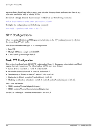
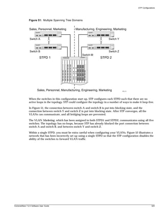
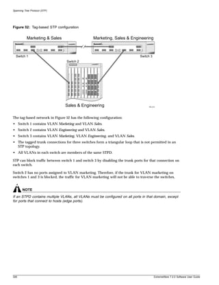
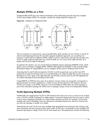
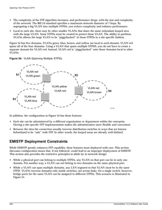
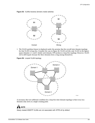
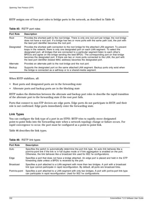
![Rapid Spanning Tree Protocol
Configuring Link Types. By default, all ports are broadcast links. To configure the ports in an STPD,
use the following command:
configure stpd <spanning tree name> ports link-type [auto | edge | broadcast |
point-to-point] <portlist>
• auto—Configures the ports as auto links. If the link is in full duplex mode, or if link aggregation is
enabled on the port, an auto link behaves like a point-to-point link.
• edge—Configures the ports as edge ports.
• point-to-point—Configures the ports for an RSTP environment.
To display detailed information about the ports in an STPD, use the following command:
show stpd <spanning tree name> ports <portlist> {detail}
RSTP Timers
For RSTP to rapidly recover network connectivity, RSTP requires timer expiration. RSTP derives many
of the timer values from the existing configured STP timers to meet its rapid recovery requirements
rather than relying on additional timer configurations. Table 47 describes the user configurable timers,
and Table 48 describes the timers that are derived from other timers and not user configurable.
Table 47: User configurable timers
Timer Description
Hello The root bridge uses the hello timer to send out configuration BPDUs through all of
its forwarding ports at a pre-determined, regular time interval. The default value is 2
seconds. The range is 1 to 10 seconds.
Forward delay A port moving from the blocking state to the forwarding state uses the forward delay
timer to transition through the listening and learning states. In RSTP, this timer
complements the rapid configuration behavior. If none of the rapid rules are in effect,
the port uses legacy STP rules to move to the forwarding state. The default is 15
seconds. The range is 4 to 30 seconds.
Table 48: Derived timers
Timer Description
TCN The root port uses the TCN timer when it detects a change in the network topology.
The TCN timer stops when the topology change timer expires or upon receipt of a
topology change acknowledgement. The default value is the same as the value for
the bridge hello timer.
Topology Change The topology change timer determines the total time it takes the forwarding ports to
send configuration BPDUs. The default value for the topology change timer depends
upon the mode of the port.
• 1d mode—The sum of the forward delay timer (default value is 15 seconds;
range of 4 to 30 seconds) and the max age timer (default value is 20 seconds;
range of 6 to 40 seconds).
• 1w mode—Double the hello timer (default value is 4 seconds)
Message age A port uses the message age timer to time out receiving BPDUs. When a port
receives a superior or equal BPDU, the timer restarts. When the timer expires, the
port becomes a designated port and a configuration update occurs. If the bridge
operates in 1w mode and receives an inferior BPDU, the timer expires early. The
default value is the same as the STPD bridge max age parameter.
ExtremeWare 7.2.0 Software User Guide 333](https://image.slidesharecdn.com/extremewareuserguide72-110124002726-phpapp01/85/Extreme-wareuserguide72-333-320.jpg)
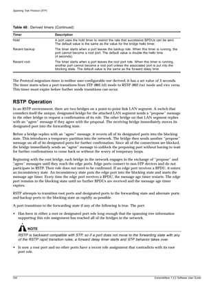
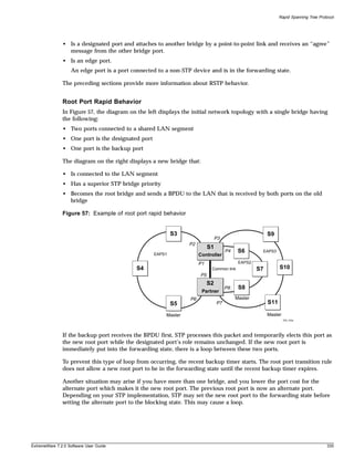
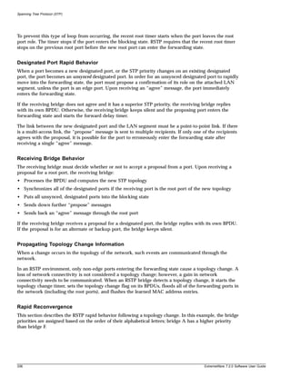
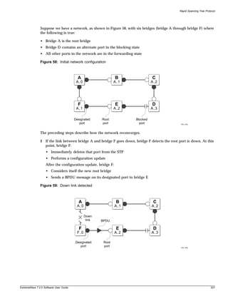
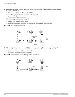
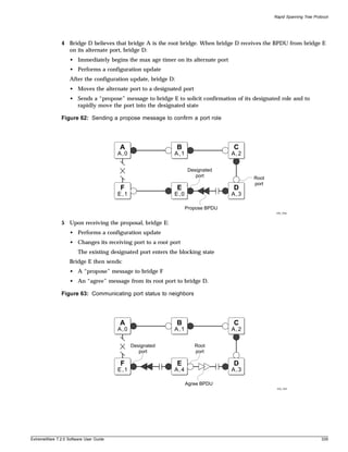
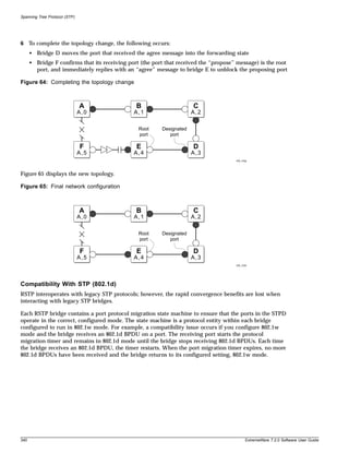
![STP Rules and Restrictions
STP Rules and Restrictions
This section summarizes the rules and restrictions for configuring STP.
• The StpdID must be the VLANid of one of its member VLANs, and that VLAN can not be
partitioned.
• A default VLAN can not be partitioned. If a VLAN traverses multiple STP domains, the VLAN must
be tagged.
• An STPD can carry, at most, one VLAN running in PVST+ mode, and its StpdID must be identical
with that VLANid. In addition, the PVST+ VLAN can not be partitioned.
• The default VLAN of a PVST+ port must be identical with the native VLAN on the PVST+ device
connected to that port.
• If a port supports 802.1w-STPD, then the port must be configured with a default VLAN. If not, the
BPDUs for that STPD are not flooded when the STPD is disabled.
• If an STPD contains both PVST+ and non-PVST+ ports, it must be enabled. If it is disable, the
BPDUs are flooded in the format of the incoming STP port, which may be incompatible with those of
the connected devices.
Configuring STP on the Switch
To configure basic STP, follow these steps:
1 Create one or more STP domains using the following command:
create stpd <name>
NOTE
STPD, VLAN, and QoS profile names must all be unique. For example, a name used to identify a
VLAN cannot be used when you create an STPD or a QoS profile.
2 Add one or more VLANs to the STPD using the following command:
configure stpd <spanning tree name> add vlan <vlan name> {ports <portlist> [dot1d
| emistp | pvst-plus]}
3 Enable STP for one or more STP domains using the following command:
enable stpd {<spanning tree name>}
After you have created the STPD, you can optionally configure STP parameters for the STPD.
NOTE
You should not configure any STP parameters unless you have considerable knowledge and experience
with STP. The default STP parameters are adequate for most networks.
The following parameters can be configured on each STPD:
• Hello time
• Forward delay
• Max age
ExtremeWare 7.2.0 Software User Guide 341](https://image.slidesharecdn.com/extremewareuserguide72-110124002726-phpapp01/85/Extreme-wareuserguide72-341-320.jpg)
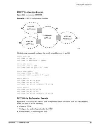
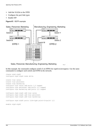
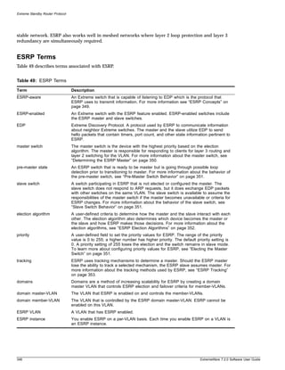
![ESRP Concepts
ESRP Concepts
ESRP is configured on a per-VLAN basis on each switch. A maximum of four switches can participate
in providing redundant layer 3 or layer 2 services to a single VLAN. The switches exchange keep-alive
packets for each VLAN independently. Only one switch (the master) can actively provide layer 3
routing and/or layer 2 switching for each VLAN. This switch handles the forwarding, ARP requests,
and routing for this particular VLAN. Other participating switches for the VLAN are in slave mode
waiting for an ESRP state change.
For a VLAN with ESRP enabled, each participating switch uses the same MAC address and must be
configured with the same IP address or IPX NetID. It is possible for one switch to be master for one or
more VLANs while being in slave for others, thus allowing the load to be split across participating
switches.
NOTE
If you configure OSPF and ESRP, you must manually configure an OSPF router identifier (ID). Be sure
that you configure a unique OSPF router ID on each switch running ESRP. For more information on
configuring OSPF, see Chapter 18.
To have two or more switches participate in ESRP, the following must be true:
• For each VLAN to be made redundant, the switches must have the ability to exchange packets on
the same layer 2 broadcast domain for that VLAN. Multiple paths of exchange can be used, and
typically exist in most network system designs that take advantage of ESRP.
• For a VLAN to be recognized as participating in ESRP, the assigned IP address or the IPX NETid for
the separate switches must be identical. Other aspects of the VLAN, including its name, are ignored.
• ESRP must be enabled on the desired VLANs for each switch.
NOTE
ESRP cannot be enabled on the VLAN default.
• Extreme Discovery Protocol (EDP) must be enabled on the ports that are members of the ESRP
VLANs (The default setting is enabled.).
To verify EDP status, use the following command:
show ports {mgmt | <portlist>} [t1 | e1 | t3] info
NOTE
If you configure a domain master-VLAN for ESRP, the domain master-VLAN must contain all ports
belonging to the domain member-VLANs in order to operate properly as an ESRP VLAN.
ESRP-Aware Switches
Extreme switches that are not running ESRP, but are connected on a network that has other Extreme
switches running ESRP are ESRP-aware. When ESRP-aware switches are attached to ESRP-enabled
switches, the ESRP-aware switches reliably perform fail-over and fail-back scenarios in the prescribed
recovery times. No configuration of this feature is necessary.
ExtremeWare 7.2.0 Software User Guide 349](https://image.slidesharecdn.com/extremewareuserguide72-110124002726-phpapp01/85/Extreme-wareuserguide72-349-320.jpg)
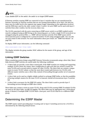
![Extreme Standby Router Protocol
NOTE
Enabling environmental tracking on a BlackDiamond chassis with only one power supply unit (PSU)
installed causes tracking to fail. In this case, the tracking failure occurs by design.
To configure the failover priority for ESRP VLAN, follow these steps:
1 Assign a priority to each ESRP VLAN, using the following command:
configure vlan <vlan name> esrp priority <value>
The range of the priority value is 0 to 254; a higher number has a higher priority. The default priority
setting is 0.
NOTE
If you set the priority to 255, the ESRP VLAN will remain in slave mode even if the master ESRP
VLAN fails.
You will typically configure both ESRP VLANs with the same priority.
2 Assign the priority flag precedence over the active ports count, using the following command:
configure vlan <vlan name> esrp esrp-election [ports-track-priority |
ports-track-priority-mac | track-ports-priority | track-ports-priority-mac |
priority-ports-track-mac | priority-track-ports-mac | priority-mac-only]
Because the priority of both ESRP VLANs are set to the same value, ESRP will use the active ports
count to determine the master ESRP VLAN.
3 Set the failover priority, using the following command:
configure vlan <vlan name> add [track-diagnostic | track-environment | track-rip |
track-bgp | track-ospf] failover <priority>
Where:
— track-bgp tracks for any available BGP route.
— track-diagnostic tracks for any diagnostics failure.
— track-environment tracks for any environmental failure.
— track-ospf tracks for any available OSPF route.
— track-rip tracks for any available RIP route.
The range of the priority value is 0 to 254; a higher number has a higher priority. The default priority
setting is 0.
Typically you will set the failover priority lower than the configured priority. Then, if one of the
ESRP VLANs experiences a hardware or diagnostics failure, it will become the standby VLAN.
ESRP VLAN Tracking
You can configure ESRP to track port connectivity to one or more specified VLANs as criteria for
failover. The number of VLAN active ports are tracked. If the switch is no longer connected to the
specified VLANs, the switch automatically relinquishes master status and remains in slave mode. You
can track a maximum of four routes per VLAN.
To add or delete a tracked VLAN, use one of the following commands:
configure vlan <vlan name> add track-vlan <vlan_tracked>>
354 ExtremeWare 7.2.0 Software User Guide](https://image.slidesharecdn.com/extremewareuserguide72-110124002726-phpapp01/85/Extreme-wareuserguide72-354-320.jpg)
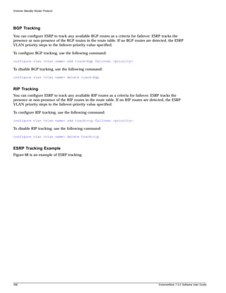
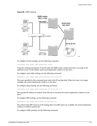
![Extreme Standby Router Protocol
configure vlan esrp1 add track-ospf failover 20
The switch tracks OSPF routes in its IP routing table. If no OSPF routes are available, the switch
implements a failover to failover priority 20.
To configure BGP tracking, use the following command:
configure vlan esrp1 add track-bgp failover 20
The switch tracks BGP routes in its IP routing table. If no BGP routes are available, the switch
implements a failover to failover priority 20.
ESRP Port Restart
You can configure ESRP to restart ports in the ESRP master VLAN when the downstream switch is a
non-Extreme switch. This action takes down and restarts the port link to clear and refresh the
downstream ARP table. To configure port restart, use the following command:
configure vlan <vlan name> add ports [<portlist> | all] restart
To disable port restart, use the following command:
configure vlan <vlan name> add ports [<portlist> | all] no-restart
If a switch becomes a slave, ESRP takes down (disconnects) the physical links of member ports that
have port restart enabled. The disconnection of these ports causes downstream devices to remove the
ports from their FDB tables. This feature allows you to use ESRP in networks that include equipment
from other vendors. After 3 seconds the ports re-establish connection with the ESRP switch.
To remove a port from the restart configuration, delete the port from the VLAN and re-add it.
NOTE
The port restart feature is also available for VRRP. For more information on VRRP, see Chapter 16.
ESRP and VLAN Aggregation
ESRP can be used to provide redundant default router protection to VLAN aggregation clients. ESRP is
enabled on the super-VLAN only (not the sub-VLANs). The procedure is to add ports to the
super-VLAN that is shared with the sub-VLANs. To do so, the super-VLAN should be configured with
an 802.1Q tag, and added as tagged with the sub-VLAN ports to avoid a protocol conflict. Lastly, enable
ESRP on the super-VLAN.
NOTE
All ports must be tagged for the super-VLAN.
The following example combines ESRP and VLAN aggregation for the super-VLAN vsuper and two
sub-VLANs, v1sub and v2sub, that have ports 1 and 2 as members, respectively.
1 Create the VLANs and set up the super to sub-VLAN relationship.
create vlan v1sub
create vlan v2sub
358 ExtremeWare 7.2.0 Software User Guide](https://image.slidesharecdn.com/extremewareuserguide72-110124002726-phpapp01/85/Extreme-wareuserguide72-358-320.jpg)
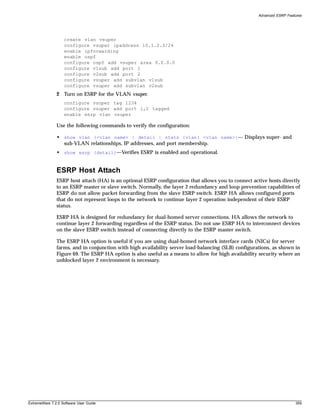
![Extreme Standby Router Protocol
Figure 69: ESRP host attach
OSPF/BGP-4
EW_045
ESRP VLANs that share ESRP HA ports must be members of different ESRP groups. Each port can have
a maximum of four VLANs.
When using load sharing with the ESRP HA feature, configure all ports in the same load-sharing group
as host attach ports.
Other applications allow lower cost redundant routing configurations, because hosts can be directly
attached to the switch involved with ESRP. The ESRP HA feature is used only on switches and I/O
modules that have the “i” series chipset. It also requires at least one link between the master and the
slave ESRP switch for carrying traffic and to exchange ESRP hello packets.
NOTE
Do not use the ESRP HA feature with the following protocols: STP, EAPS, or VRRP. A broadcast storm
may occur.
ESRP Don’t Count
ESRP don’t count is an optional ESRP port configuration that allows the port to be part of the VLAN,
but if a link failure occurs, it will not trigger a reconvergence. The don’t count feature has the effect of
not counting the host ports and normal ports as active ports. This has the convenience of minimal ESRP
state changes due to frequent client activities like reboots and unplugging laptops.
When using load sharing with the ESRP don’t count feature, configure all ports in the same
load-sharing group as don’t count ports.
To configure don’t count on either a host attach port or a normal port, use the following command:
configure esrp port-mode [host | normal] ports <portlist> {don’t-count}
ESRP Domains
ESRP domains is an optional ESRP configuration that allows you to configure multiple VLANs under
the control of a single instance of the ESRP protocol. By grouping multiple VLANs under one ESRP
360 ExtremeWare 7.2.0 Software User Guide](https://image.slidesharecdn.com/extremewareuserguide72-110124002726-phpapp01/85/Extreme-wareuserguide72-360-320.jpg)
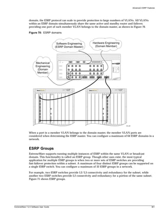
![Extreme Standby Router Protocol
Figure 71: ESRP groups
ESRP ESRP
Group1 Group1
Master Standby
ESRP ESRP Group2 Standby
Group2 (L2 only)
Master
(L2 only)
EW_056
NOTE
A switch cannot perform both master and slave functions on the same VLAN for separate instances of
ESRP.
An additional user for ESRP groups is ESRP Host Attach (HA), described on page 359.
Selective Forwarding
An ESRP-aware switch floods ESRP PDUs to all ports in an ESRP-aware VLAN and the CPU. This
flooding increases the amount of network traffic because all ports, regardless if they are connected to
switches running the same ESRP group or not, receive ESRP PDUs. To reduce the amount of traffic, you
can select the ports that receive ESRP PDUs by configuring selective forwarding on an ESRP-aware
VLAN. By configuring selective forwarding, you create a portlist for the ESRP groups associated with
an ESRP-aware VLAN, and that portlist is used for forwarding ESRP PDUs on the relevant ports only.
You configure this feature on a per-VLAN basis, and selective forwarding is disabled by default.
NOTE
Extreme Networks recommends keeping the default settings unless you have considerable knowledge
and experience with ESRP.
To configure selective forwarding, use the following command:
configure vlan <vlan name> esrp group <group_number> add esrp-aware-ports [all |
<portlist>]
362 ExtremeWare 7.2.0 Software User Guide](https://image.slidesharecdn.com/extremewareuserguide72-110124002726-phpapp01/85/Extreme-wareuserguide72-362-320.jpg)
![Displaying ESRP Information
where the following is true:
• vlan name—Specifies an ESRP-aware VLAN name.
• group number—Specifies the ESRP group to which this ESRP-aware VLAN belongs. The ESRP
group number must be the same as the ESRP-aware VLAN number.
• all—Specifies all of the ports to be configured. All of the ports must be connected to switches
running ESRP, and the ports must connect to the ESRP master and slave switches.
• portlist—Specifies the ports to be configured. The selected ports must be connected to switches
running ESRP, and the ports must connect to the ESRP master and slave switches. May be in the
form 1, 2, 3-5, 2:*, 2:5, 2:6-2:8.
When an ESRP-aware switch receives an ESRP PDU, the software will lookup the group to which the
PDU belongs and will forward the ESRP PDU to the group's portlist and the CPU.
You cannot enable selective forwarding on an ESRP-enabled VLAN. If you try to enable selective
forwarding on an ESRP-enabled VLAN, you see the following message:
ERROR: vlan meg is esrp enabled. Cannot enable selective forwarding on esrp vlans
To disable selective forwarding, use the following command:
configure vlan <vlan name> esrp group <group_number> delete esrp-aware-ports [all |
<portlist>]
where the following is true:
• group number—Specifies the ESRP group to which this ESRP-aware VLAN belongs. The ESRP
group number must be the same number as the ESRP-aware VLAN.
• all—Specifies all of the ports to be disabled.
• portlist—Specifies the selected ports to be disabled.
Displaying Selective Forwarding Information
To display the ESRP-aware VLAN(s), the ESRP group(s), and the ESRP-aware port(s) that receive ESRP
PDUs, use the following command:
show esrp-aware-ports {vlan <vlan name>}
Displaying ESRP Information
To verify the operational state of an ESRP VLAN and the state of its neighbor, use the following
command:
show esrp {detail}
If you enter the show esrp command without a keyword, the command displays summary ESRP
status information for the VLANs on the switch. Use the detail keyword to display more detailed
status information.
To view tracking information about a particular VLAN, including the VLANs tracked by it and a list of
the VLANs tracking it, use the following command:
show vlann
ExtremeWare 7.2.0 Software User Guide 363](https://image.slidesharecdn.com/extremewareuserguide72-110124002726-phpapp01/85/Extreme-wareuserguide72-363-320.jpg)
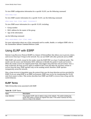
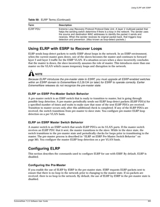
![Extreme Standby Router Protocol
To enable the use of ELRP by ESRP in the pre-master state on a per-VLAN basis, and to configure how
often and how many ELRP PDUs are sent in the pre-master state, use the following command:
configure vlan <vlan name> esrp elrp-premaster-poll enable {count <number> | interval
<seconds>}
where the following is true:
• vlan name—Specifies an ESRP-enabled VLAN name.
• number—Specifies the number of times the switch sends ELRP PDUs. The default is 3, and the range
is 1 to 32.
• seconds—Specifies how often, in seconds, the ELRP PDUs are sent. The default is 1 seconds, and the
range is 1 to 32 seconds.
To disable the use of ELRP by ESRP in the pre-master state, use the following command:
configure vlan <vlan name> esrp elrp-premaster-poll disable
Configuring the Master
If you enable the use of ELRP by ESRP in the master state, ESRP requests that ELRP packets are
periodically sent to ensure that there is no loop in the network while ESRP is in the master state. By
default, the use of ELRP by ESRP in the master state is disabled.
To enable the use of ELRP by ESRP in the master state on a per-VLAN basis, and to configure how
often the master checks for loops in the network, use the following command:
configure vlan <vlan name> esrp elrp-master-poll enable {interval <seconds>}
where the following is true:
• vlan name—Specifies and ESRP-enabled VLAN name.
• seconds—Specifies how often, in seconds, successive ELRP packets are sent. The default is 1 second,
and the range is 1 to 32 seconds.
To disable the use of ELRP by ESRP in the master state, use the following command:
configure vlan <vlan name> esrp elrp-master-poll disable
Configuring Ports
You can configure one or more ports of a VLAN where ELRP packet transmission is requested by ESRP.
This allows the ports in your network that might experience loops, such as ports that connect to the
master, slave, or ESRP-aware switches, to receive ELRP packets. You do not need to send ELRP packets
to host ports.
By default, all ports of the VLAN where ESRP is enabled also has ELRP transmission enabled on the
ports.
If you change your network configuration, and a port no longer connects to a master, slave, or
ESRP-aware switch, you can disable ELRP transmission on that port. To disable ELRP transmission, use
the following command:
configure vlan <vlan name> delete elrp-poll ports [<portlist> | all]
366 ExtremeWare 7.2.0 Software User Guide](https://image.slidesharecdn.com/extremewareuserguide72-110124002726-phpapp01/85/Extreme-wareuserguide72-366-320.jpg)
![ESRP Examples
To enable ELRP transmission on a port, use the following command:
configure vlan <vlan name> add elrp-poll ports [<portlist> | all]
Displaying ELRP Information
To display summary ELRP information, use the following command:
show elrp {<vlan name> | detail}
If you enter the show elrp command without a keyword, the command displays the total number of:
• Clients registered with ELRP
• ELRP packets transmitted
• ELRP packets received
Use the vlan name parameter to display information specific to a VLAN, and the detail keyword to
display more detailed status information for VLANs in the master and pre-master states.
For more detailed information about the output associated with the show elrp command, see the
ExtremeWare Command Reference Guide.
ESRP Examples
This section provides examples of ESRP configurations.
Single VLAN Using Layer 2 and Layer 3 Redundancy
This example, shown in Figure 72, uses a number of Summit switches that perform layer 2 switching for
VLAN Sales. The Summit switches are dual-homed to the BlackDiamond switches. The BlackDiamond
switches perform layer 2 switching between the Summit switches and layer 3 routing to the outside
world. Each Summit switch is dual-homed using active ports to two BlackDiamond switches (as many
as four could be used). ESRP is enabled on each BlackDiamond switch only for the VLAN that
interconnects to the Summit switches. Each BlackDiamond switch has the VLAN Sales configured using
the identical IP address. The BlackDiamond switches then connect to the routed enterprise normally,
using the desired routing protocol (for example RIP or OSPF).
ExtremeWare 7.2.0 Software User Guide 367](https://image.slidesharecdn.com/extremewareuserguide72-110124002726-phpapp01/85/Extreme-wareuserguide72-367-320.jpg)
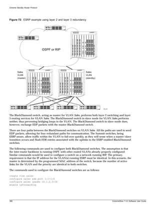
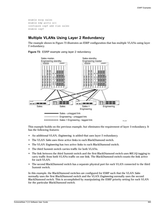
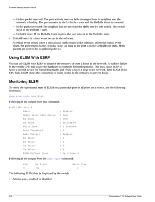
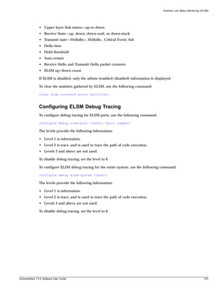

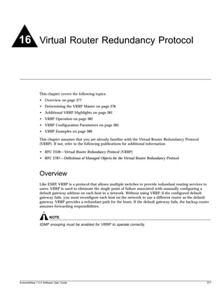
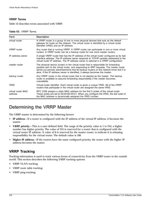
![Determining the VRRP Master
VRRP VLAN Tracking
You can configure VRRP to track connectivity to one or more specified VLANs as criteria for failover. If
no active ports remain on the specified VLANs, the router automatically relinquishes master status and
remains in backup mode.
To add or delete a tracked VLAN, use one of the following commands:
configure vlan <vlan name> add track-vlan <vlan_tracked>
configure vlan <vlan name> delete track-vlan <vlan_tracked>
VRRP Route Table Tracking
You can configure VRRP to track specified routes in the route table as criteria for failover. If any of the
configured routes are not available within the route table, the router automatically relinquishes master
status and remains in backup mode.
To add or delete a tracked route, use the following command:
configure vlan <vlan name> add track-iproute <ip address>/<masklength>
VRRP Ping Tracking
You can configure VRRP to track connectivity using a simple ping to any outside responder. The
responder may represent the default route of the router, or any device meaningful to network
connectivity of the master VRRP router. The router automatically relinquishes master status and
remains in backup mode if a ping keepalive fails three consecutive times.
To add or delete a tracked route, use one of the following commands:
configure vlan <vlan name> add track-ping <ip address> frequency <seconds> miss
<number>
configure vlan <vlan name> delete track-ping <ipaddress>
To view the status of tracked devices, use the following command:
show vrrp [vlan <vlan name> | all] {detail}
ExtremeWare 7.2.0 Software User Guide 379](https://image.slidesharecdn.com/extremewareuserguide72-110124002726-phpapp01/85/Extreme-wareuserguide72-379-320.jpg)
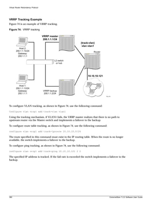
![Virtual Router Redundancy Protocol
• VRRP and Spanning Tree can be simultaneously enabled on the same switch.
• VRRP and ESRP cannot be simultaneously enabled on the same switch.
VRRP Port Restart
You can configure VRRP to restart ports if those ports are members of a VLAN that becomes a backup.
To configure port restart, use the following command:
configure vlan <vlan name> add ports [<portlist> | all] restart
To disable port restart, use the following command:
configure vlan <vlan name> add ports [<portlist> | all] no-restart
If a VLAN becomes a backup, VRRP disconnects member ports that have port restart enabled. The
disconnection of these ports causes downstream devices to remove the ports from their FDB tables. This
feature allows you to use VRRP in networks that include equipment from other vendors. After 3
seconds the ports re-establish connection with the VRRP switch.
To remove a port from the restart configuration, delete the port from the VLAN and re-add it.
NOTE
The port restart feature is also available for ESRP. For more information on ESRP, see Chapter 15.
VRRP Operation
This section describes two VRRP network configuration:
• A simple VRRP network
• A fully-redundant VRRP network
Simple VRRP Network Configuration
Figure 75 shows a simple VRRP network.
382 ExtremeWare 7.2.0 Software User Guide](https://image.slidesharecdn.com/extremewareuserguide72-110124002726-phpapp01/85/Extreme-wareuserguide72-382-320.jpg)
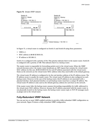
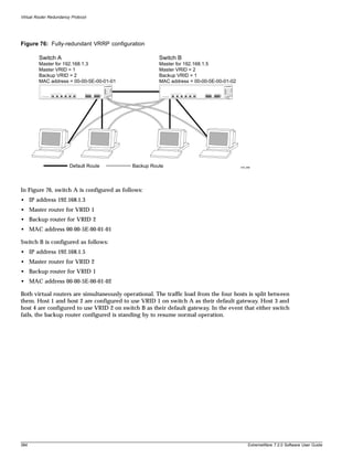
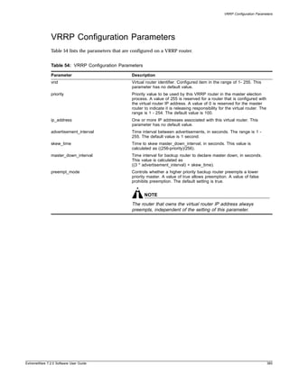
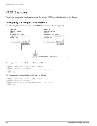
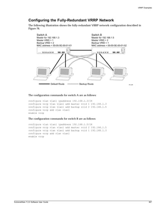

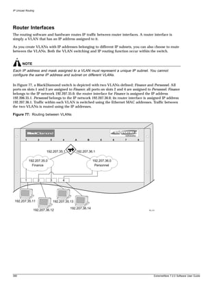
![Overview of IP Unicast Routing
Populating the Routing Table
The switch maintains an IP routing table for both network routes and host routes. The table is
populated from the following sources:
• Dynamically, by way of routing protocol packets or by ICMP redirects exchanged with other routers
• Statically, by way of routes entered by the administrator
— Default routes, configured by the administrator
— Locally, by way of interface addresses assigned to the system
— By other static routes, as configured by the administrator
NOTE
If you define a default route, and subsequently delete the VLAN on the subnet associated with the
default route, the invalid default route entry remains. You must manually delete the configured default
route.
Dynamic Routes
Dynamic routes are typically learned by way of RIP or OSPF. Routers that use RIP or OSPF exchange
information in their routing tables in the form of advertisements. Using dynamic routes, the routing
table contains only networks that are reachable.
Dynamic routes are aged out of the table when an update for the network is not received for a period of
time, as determined by the routing protocol.
Static Routes
Static routes are manually entered into the routing table. Static routes are used to reach networks not
advertised by routers.
Static routes can also be used for security reasons, to control which routes you want advertised by the
router. You can decide if you want all static routes to be advertised, using one of the following
commands:
• enable rip export static or disable rip export static
• enable ospf export static [cost <metric> [ase-type-1 | ase-type-2] {tag <number>}
| <route map>] or disable ospf export [bgp | direct | e-bgp | i-bgp | isis |
isis-level-1 | isis-level-1-external | isis-level-2 | isis-level-2-external | rip
| static | vip]
The default setting is disabled. Static routes are never aged out of the routing table.
A static route must be associated with a valid IP subnet. An IP subnet is associated with a single VLAN
by its IP address and subnet mask. If the VLAN is subsequently deleted, the static route entries using
that subnet must be deleted manually.
Multiple Routes
When there are multiple, conflicting choices of a route to a particular destination, the router picks the
route with the longest matching network mask. If these are still equal, the router picks the route using
the following criteria (in the order specified):
ExtremeWare 7.2.0 Software User Guide 391](https://image.slidesharecdn.com/extremewareuserguide72-110124002726-phpapp01/85/Extreme-wareuserguide72-391-320.jpg)
![IP Unicast Routing
• Directly attached network interfaces
• ICMP redirects
• Static routes
• Directly attached network interfaces that are not active.
NOTE
If you define multiple default routes, the route that has the lowest metric is used. If multiple default
routes have the same lowest metric, the system picks one of the routes.
You can also configure blackhole routes—traffic to these destinations is silently dropped.
IP Route Sharing
IP route sharing allows multiple equal-cost routes to be used concurrently. IP route sharing can be used
with static routes or with OSPF routes. In OSPF, this capability is referred to as equal cost multipath
(ECMP) routing. To use IP route sharing, use the following command:
enable iproute sharing
Next, configure static routes and/or OSPF as you would normally. ExtremeWare supports unlimited
route sharing across static routes and up to 12 ECMP routes for OSPF.
Route sharing is useful only in instances where you are constrained for bandwidth. This is typically not
the case using Extreme switches. Using route sharing makes router troubleshooting more difficult
because of the complexity in predicting the path over which the traffic will travel.
Route Maps
Route maps for IP routing can be configured based on the route origin. When routes are added to the IP
routing table from various source, the route map configured for the origin of the route is applied to the
route. After matching on specified characteristics, the characteristics for the route can be modified using
the route maps. The characteristics that can be matched and modified are dependent on the origin of the
route. Route maps for IP routing can be dynamically changed. In the case of direct and static route
origins, the changes are reflected immediately. In the case of routes that are sourced from other origin,
the changes are reflected within 30 seconds.
To configure route maps for IP routing, use the following command:
configure iproute route-map [bgp | direct | e-bgp | i-bgp | ospf | ospf-extern1 |
ospf-extern2 | ospf-inter | ospf-intra | rip | static] [<route map> | none]
To view the route maps for IP routing, use the following command:
show iproute route-map
Subnet-Directed Broadcast Forwarding
You can enable or disable the hardware forwarding of subnet-directed broadcast IP packets. This allows
the switch to forward subnet-directed broadcast packets at wire-speed.
To enable or disable hardware forwarding, use one the following commands:
[enable | disable] ipforwarding fast-direct-broadcast [vlan <vlan_name>]
392 ExtremeWare 7.2.0 Software User Guide](https://image.slidesharecdn.com/extremewareuserguide72-110124002726-phpapp01/85/Extreme-wareuserguide72-392-320.jpg)
![Proxy ARP
The entries are added to the IP forwarding table as standard entries and you can view them using the
show ipfdb command.
You can also configure the VLAN router interface to either forward and process all subnet-directed
broadcast packets, or to simply forward these packets after they have been added to the IP forwarding
database. The latter option allows you to improve CPU forwarding performance by having upper
layers, such as UDP and TCP, ignore broadcast packet processing (for example, if the packets have
IP-options configured).
To enable or disable broadcast packet processing, use the following command:
[enable | disable] ipforwarding ignore-broadcast vlan <vlan_name>
Using these commands together, you can achieve a 30-50% reduction in system processing cycles in
forwarding subnet-directed broadcast traffic on a BlackDiamond switch, and a 100% reduction on the
Alpine and Summit switches.
NOTE
Although forwarding performance is improved in the BlackDiamond switch, the CPU continues to
observe the subnet-directed broadcast packets and does not ignore such packets when traversing
modules in a BlackDiamond switch. Only I/O modules containing the “i” series chipset support this
command on the BlackDiamond switch.
Proxy ARP
Proxy Address Resolution Protocol (ARP) was first invented so that ARP-capable devices could respond
to ARP Request packets on behalf of ARP-incapable devices. Proxy ARP can also be used to achieve
router redundancy and simplify IP client configuration. The switch supports proxy ARP for this type of
network configuration. The section describes some example of how to use proxy ARP with the switch.
ARP-Incapable Devices
To configure the switch to respond to ARP Requests on behalf of devices that are incapable of doing so,
you must configure the IP address and MAC address of the ARP-incapable device using the use the
following command:
configure iparp add proxy <ip address> {<mask>} {<mac_address>} {always}
Once configured, the system responds to ARP Requests on behalf of the device as long as the following
conditions are satisfied:
• The valid IP ARP Request is received on a router interface.
• The target IP address matches the IP address configured in the proxy ARP table.
• The proxy ARP table entry indicates that the system should always answer this ARP Request,
regardless of the ingress VLAN (the always parameter must be applied).
Once all the proxy ARP conditions are met, the switch formulates an ARP Response using the
configured MAC address in the packet.
ExtremeWare 7.2.0 Software User Guide 393](https://image.slidesharecdn.com/extremewareuserguide72-110124002726-phpapp01/85/Extreme-wareuserguide72-393-320.jpg)
![IP Unicast Routing
Proxy ARP Between Subnets
In some networks, it is desirable to configure the IP host with a wider subnet than the actual subnet
mask of the segment. Proxy ARP can be used so that the router answers ARP Requests for devices
outside of the subnet. As a result, the host communicates as if all devices are local. In reality,
communication with devices outside of the subnet are proxied by the router.
For example, an IP host is configured with a class B address of 100.101.102.103 and a mask of
255.255.0.0. The switch is configured with the IP address 100.101.102.1 and a mask of 255.255.255.0. The
switch is also configured with a proxy ARP entry of IP address 100.101.0.0 and mask 255.255.0.0, without
the always parameter.
When the IP host tries to communicate with the host at address 100.101.45.67, the IP hosts
communicates as if the two hosts are on the same subnet, and sends out an IP ARP Request. The switch
answers on behalf of the device at address 100.101.45.67, using its own MAC address. All subsequent
data packets from 100.101.102.103 are sent to the switch, and the switch routes the packets to
100.101.45.67.
Relative Route Priorities
Table 55 lists the relative priorities assigned to routes depending upon the learned source of the route.
NOTE
Although these priorities can be changed, do not attempt any manipulation unless you are expertly
familiar with the possible consequences.
Table 55: Relative Route Priorities
Route Origin Priority
Direct 10
BlackHole 50
Static 1100
ICMP 1200
OSPFIntra 2200
OSPFInter 2300
RIP 2400
OSPFExtern1 3200
OSPFExtern2 3300
BOOTP 5000
To change the relative route priority, use the following command:
configure iproute priority [rip | bootp | icmp | static | ospf-intra | ospf-inter |
ospf-as-external | ospf-extern1 | ospf-extern2] <priority>
394 ExtremeWare 7.2.0 Software User Guide](https://image.slidesharecdn.com/extremewareuserguide72-110124002726-phpapp01/85/Extreme-wareuserguide72-394-320.jpg)
![Configuring IP Unicast Routing
Configuring IP Unicast Routing
This section describes the commands associated with configuring IP unicast routing on the switch. To
configure routing, follow these steps:
1 Create and configure two or more VLANs.
2 Assign each VLAN that will be using routing an IP address using the following command:
configure vlan <vlan name> ipaddress <ipaddress> {<netmask> | <mask length>}
Ensure that each VLAN has a unique IP address.
3 Configure a default route using the following command:
configure iproute add default <gateway> {<metric>}
Default routes are used when the router has no other dynamic or static route to the requested
destination.
4 Turn on IP routing for one or all VLANs using the following command:
enable ipforwarding {[broadcast | fast-direct-broadcast | ignore-broadcast]} {vlan
<vlan name>}
5 Turn on RIP or OSPF using one of the following commands:
enable ripp
enable ospff
Verifying the IP Unicast Routing Configuration
Use the show iproute command to display the current configuration of IP unicast routing for the
switch, and for each VLAN. The show iproute command displays the currently configured routes, and
includes how each route was learned.
Additional verification commands include:
• show iparp—Displays the IP ARP table of the system.
• show ipfdb—Displays the hosts that have been transmitting or receiving packets, and the port and
VLAN for each host.
• show ipconfig—Displays configuration information for one or more VLANs.
Routing Configuration Example
Figure 78 illustrates a BlackDiamond switch that has three VLANs defined as follows:
• Finance
— Protocol-sensitive VLAN using the IP protocol.
— All ports on slots 1 and 3 have been assigned.
— IP address 192.207.35.1.
• Personnel
— Protocol-sensitive VLAN using the IP protocol.
— All ports on slots 2 and 4 have been assigned.
ExtremeWare 7.2.0 Software User Guide 395](https://image.slidesharecdn.com/extremewareuserguide72-110124002726-phpapp01/85/Extreme-wareuserguide72-395-320.jpg)
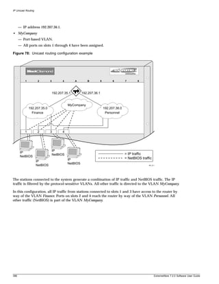
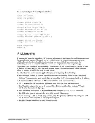
![IP Unicast Routing
Configuring DHCP/BOOTP Relay
Once IP unicast routing is configured, you can configure the switch to forward Dynamic Host
Configuration Protocol (DHCP) or BOOTP requests coming from clients on subnets being serviced by
the switch and going to hosts on different subnets. This feature can be used in various applications,
including DHCP services between Windows NT servers and clients running Windows 95. To configure
the relay function, follow these steps:
1 Configure VLANs and IP unicast routing.
2 Enable the DHCP or BOOTP relay function, using the following command:
enable bootprelay
3 Configure the addresses to which DHCP or BOOTP requests should be directed, using the following
command:
configure bootprelay add <ip address>
To delete a BOOTP relay entry, use the following command:
configure bootprelay delete [<ip address> | all]
Configuring the DHCP Relay Agent Option (Option 82)
After configuring and enabling the DHCP/BOOTP relay feature, you can enable the DHCP relay agent
option feature. This feature inserts a piece of information, called option 82, into any DHCP request
packet that is to be relayed by the switch. Similarly, if a DHCP reply received by the switch contains a
valid relay agent option, the option will be stripped from the packet before it is relayed to the client.
The DHCP relay agent option consists of two pieces of data, called sub-options. The first is the agent
circuit ID sub-option, and the second is the agent remote ID sub-option. When the DHCP relay agent
option is enabled on switches running ExtremeWare, the value of these sub-options is set as follows:
• Agent circuit ID sub-option: Contains the ID of the port on which the original DHCP request packet
was received. This ID is encoded as ((slot_number * 1000) + port_number). For example, if the DHCP
request were received on port 3:12, the agent circuit ID value would be 3012. On non-slot-based
switches, the agent circuit ID value is simply the port number.
• Agent remote ID sub-option: Always contains the Ethernet MAC address of the relaying switch.
You can display the Ethernet MAC address of the switch by issuing the show switch command.
To enable the DHCP relay agent option, use the following command after configuring the
DHCP/BOOTP relay function:
configure bootprelay dhcp-agent information option
To disable the DHCP relay agent option, use the following command:
unconfigure bootprelay dhcp-agent information option
In some instances, a DHCP server may not properly handle a DHCP request packet containing a relay
agent option. To prevent DHCP reply packets with invalid or missing relay agent options from being
forwarded to the client, use the following command:
configure bootprelay dhcp-agent information check
To disable checking of DHCP replies, use this command:
400 ExtremeWare 7.2.0 Software User Guide](https://image.slidesharecdn.com/extremewareuserguide72-110124002726-phpapp01/85/Extreme-wareuserguide72-400-320.jpg)
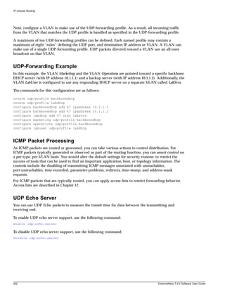
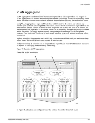
![VLAN Aggregation
Isolation Option for Communication Between Sub-VLANs
To facilitate communication between sub-VLANs, by default, an entry is made in the IP ARP table of
the super-VLAN that performs a proxy ARP function. This allows clients on one sub-VLAN to
communicate with clients on another sub-VLAN. In certain circumstances, intra-sub-VLAN
communication may not be desired for isolation reasons.
To prevent normal communication between sub-VLANs, disable the automatic addition of the IP ARP
entries on the super-VLAN using the following command:
disable subvlan-proxy-arp vlan [<super-vlan name> | all]
NOTE
The isolation option works for normal, dynamic, ARP-based client communication.
VLAN Aggregation Example
The follow example illustrates how to configure VLAN aggregation. The VLAN vsuper is created as a
super-VLAN, and sub-VLANs, vsub1, vsub2, and vsub3 are added to it.
1 Create and assign an IP address to a VLAN designated as the super-VLAN. This VLAN should have
no member ports. Be sure to enable IP forwarding, and any desired routing protocol, on the switch.
create vlan vsuper
configure vsuper ipaddress 192.201.3.1/24
enable ipforwarding
enable ospf
configure ospf add vsuper
2 Create and add ports to the sub-VLANs.
create vlan vsub1
con vsub1 add port 10-12
create vlan vsub2
configure vsub2 add po 13-15
create vlan vsub3
configure vsub3 add po 16-18
3 Configure the super-VLAN by adding the sub-VLANs.
configure vsuper add subvlan vsub1
configure vsuper add subvlan vsub2
configure vsuper add subvlan vsub3
4 Optionally, disable communication among sub-VLANs.
disable subvlan-proxy-arp vlan [<super-vlan name> | all]
Verifying the VLAN Aggregation Configuration
The following commands can be used to verify proper VLAN aggregation configuration.
• show vlan—Indicates the membership of a sub-VLANs in a super-VLAN.
• show iparp—Indicates an ARP entry that contains sub-VLAN information. Communication with a
client on a sub-VLAN must have occurred in order for an entry to be made in the ARP table.
ExtremeWare 7.2.0 Software User Guide 405](https://image.slidesharecdn.com/extremewareuserguide72-110124002726-phpapp01/85/Extreme-wareuserguide72-405-320.jpg)

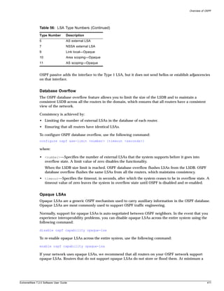
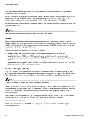
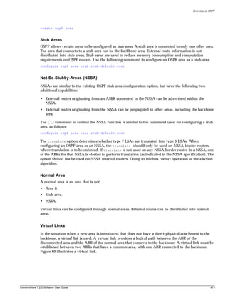
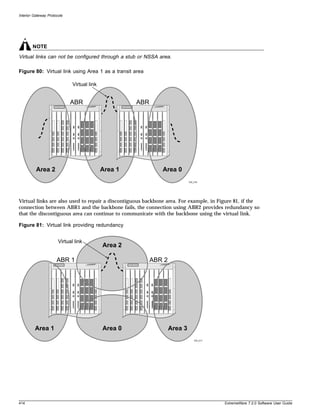
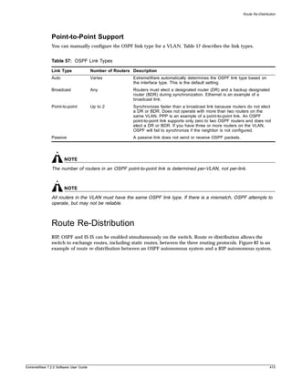
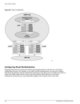
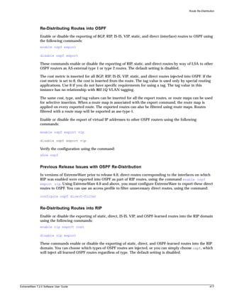
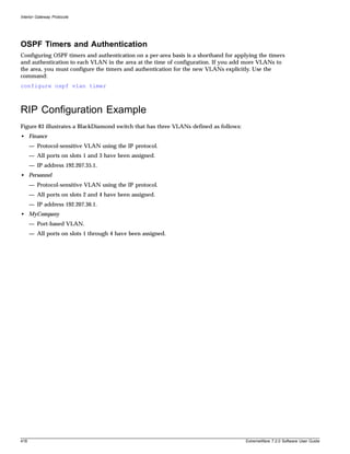
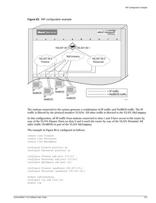
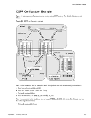
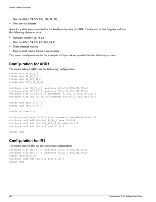
![Displaying OSPF Settings
Displaying OSPF Settings
There are a number of commands you can use to display settings for OSPF. To show global OSPF
information, use the show ospf command with no options.
To display information about one or all OSPF areas, use the following command:
show ospf area <area identifier>
The detail option displays information about all OSPF areas in a detail format.
To display information about OSPF interfaces for an area, a VLAN, or for all interfaces, use the
following command:
show ospf interfaces {vlan <vlan name> | area <area identifier>}
The detail option displays information about all OSPF interfaces in a detail format.
OSPF LSDB Display
ExtremeWare provides several filtering criteria for the show ospf lsdb command. You can specify
multiple search criteria and only results matching all of the criteria are displayed. This allows you to
control the displayed entries in large routing tables.
To display the current link-state database, use the following command:
show ospf lsdb area [all | <area identifier>[/<len>] | detail | interface | lsid
<id>[/<len>] | lstype [all | as-external | external-type7 | network | opaque-area |
opaque-global | opaque-local | router | summary-asb |summary-net| routerid
<id>[/<len>] | stats | summary | vlan <vlan name>]
The detail option displays all fields of matching LSAs in a multi-line format. The summary option
displays several important fields of matching LSAs, one line per LSA. The stats option displays the
number of matching LSAs, but not any of their contents. If not specified, the default is to display in the
summary format.
A common use of this command is to omit all optional parameters, resulting in the following shortened
form:
show ospf lsdb
The shortened form displays all areas and all types in a summary format.
ExtremeWare 7.2.0 Software User Guide 423](https://image.slidesharecdn.com/extremewareuserguide72-110124002726-phpapp01/85/Extreme-wareuserguide72-423-320.jpg)
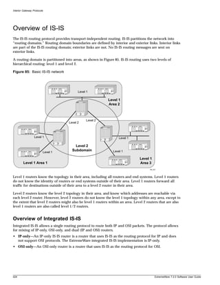
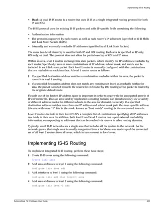
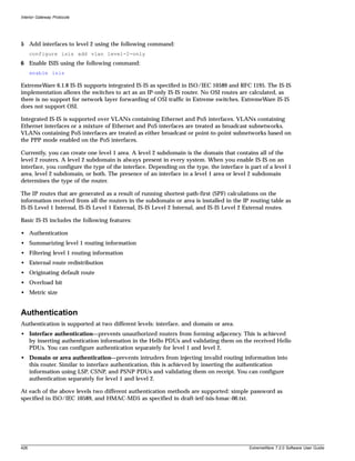
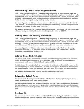
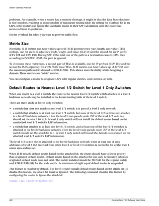


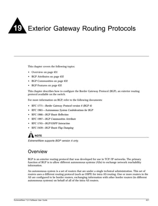
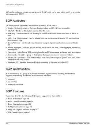
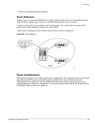
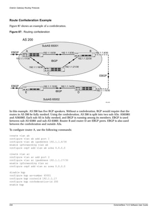
![Exterior Gateway Routing Protocols
• source-interface
• soft-in-reset
• password
Adding Neighbors to a BGP Peer Group
To create a new neighbor and add it to a BGP peer group, use the following command:
create bgp neighbor <ip address> peer-group <peer group> {multi-hop}
The new neighbor is created as part of the peer group and inherits all of the existing parameters of the
peer group. The peer group must have remote AS configured.
To add an existing neighbor to a peer group, use the following command:
configure bgp neighbor [<ip address> | all] peer-group <peer group> {acquire-all}
If you do not specify acquire-all, only the mandatory parameters are inherited from the peer group. If
you specify acquire-all, all of the parameters of the peer group are inherited. This command disables the
neighbor before adding it to the peer group.
To remove a neighbor from a peer group, use the following command:
configure bgp neighbor [<ip address> | all] peer-group none
When you remove a neighbor from a peer group, it retains the parameter settings of the group. The
parameter values are not reset to those the neighbor had before it inherited the peer group values.
BGP Route Flap Dampening
Route flap dampening is a BGP feature designed to minimize the propagation of flapping routes across
an internetwork. A route is considered to be flapping when it is repeatedly available, then unavailable,
then available, then unavailable, and so on. When a route becomes unavailable, a Withdrawal message
is sent to other connected routers, which in turn propagate the Withdrawal message to other routers. As
the route becomes available again, an Advertisement message is sent and propagated throughout the
network. As a route repeatedly changes from available to unavailable, large numbers of messages
propagate throughout the network. This is a problem in an internetwork connected to the Internet
because a route flap in the Internet backbone usually involves many routes.
Minimizing the Route Flap
The route flap dampening feature minimizes the flapping problem as follows. Suppose that the route to
network 172.25.0.0 flaps. The router (in which route dampening is enabled) assigns network 172.25.0.0 a
penalty of 1000 and moves it to a “history” state in which the penalty value is monitored. The router
continues to advertise the status of the route to neighbors. The penalties are cumulative. When the route
flaps so often that the penalty exceeds a configurable suppress limit, the router stops advertising the
route to network 172.25.0.0, regardless of how many times it flaps. Thus, the route is dampened.
The penalty placed on network 172.25.0.0 is decayed until the reuse limit is reached, upon which the
route is once again advertised. At half of the reuse limit, the dampening information for the route to
network 172.25.0.0 is removed.
The penalty is decayed by reducing the penalty value by one-half at the end of a configurable time
period, called the half-life. Routes that flap many times may reach a maximum penalty level, or ceiling,
after which no additional penalty is added. The ceiling value is not directly configurable, but the
438 ExtremeWare 7.2.0 Software User Guide](https://image.slidesharecdn.com/extremewareuserguide72-110124002726-phpapp01/85/Extreme-wareuserguide72-438-320.jpg)
![BGP Features
configuration parameter used in practice is the maximum route suppression time. No matter how often
a route has flapped, once it stops flapping, it will again be advertised after the maximum route
suppression time.
Configuring Route Flap Dampening
BGP route flap dampening can be enabled on a per BGP peer session basis, for a BGP peer group, or for
a set of routes, using a route map.
Use the following command to enable route flap dampening over BGP peer sessions:
configure bgp neighbor [<ip address> | all] dampening {{<half-life> {<reuse>
<suppress> <max-suppress> }} | {route-map <route map>}}
Use the following command to enable route flap dampening for a BGP peer group:
configure bgp neighbor [<ip address> | all] dampening {{<half-life> {<reuse>
<suppress> <max-suppress> }} | {route-map <route map>}}
You can supply the dampening parameters through the route map or directly in the CLI command, but
not both (these are mutually exclusive).
For route maps there is a set operation to configure dampening parameters. Use the following
command to add a set statement to a route map for dampening:
configure route-map <route map> <sequence number> add set dampening <half-life>
<reuse-limit> <suppress-limit> <max-suppress>
Disabling Route Flap Dampening
Use the following command to disable route flap dampening for a BGP neighbor (disabling the
dampening will also delete all the configured dampening parameters):
configure bgp neighbor [<ipaddress> | all] no-dampening
Use the following command to disable route flap dampening for a BGP peer group:
configure bgp peer-group <name> no-dampening
Viewing the Route Flap Dampening Configuration
Use the following command to view the configured values of the route flap dampening parameters for
a BGP neighbor:
show bgp neighbor <ip address> {[accepted-routes | flap-statistics | received-routes |
rejected-routes | suppressed-routes | transmitted-routes] {detail} [community
[access-profile <access profile> | no-advertise | no-export | no-export-subconfed |
number <community number> | <autonomous system id>:<bgp community>] | as-path
[<as-path-expression> | access-profile <access profile>] | route-map <route map> |
network <ip address>/<mask> {exact} | all]}
Use the following command to view the configured values of the route flap dampening parameters for
a BGP peer group:
show bgp peer-group {detail | <peer group> {detail}}
ExtremeWare 7.2.0 Software User Guide 439](https://image.slidesharecdn.com/extremewareuserguide72-110124002726-phpapp01/85/Extreme-wareuserguide72-439-320.jpg)
![Exterior Gateway Routing Protocols
Viewing Route Flap Statistics
Use the following command to view the flap statistics of a particular route from BGP neighbor:
show bgp neighbor <ip address> flap-statistics network <ip address>/<mask> {exact}
Use the following command to view the flap statistics of all the routes from a particular BGP neighbor:
show bgp neighbor <ip address> flap-statistics {detail} all
Use the following command to view the flap statistics of all the routes which matches a route map filter
from a particular BGP neighbor:
show bgp neighbor <ip address> flap-statistics {detail} route-map <route map>
Use the following command to view the flap statistics of all the routes which matches a community
criteria from a particular BGP neighbor:
show bgp neighbor <ip address> flap-statistics {detail} [community [access-profile
<access-profile> | <autonomous-system-id>:<bgp-community> | number <community_number>
| no-advertise | no-export | no-export-subconfed]
Use the following command to view the flap statistics of all the routes which matches a AS-PATH
criteria from a particular BGP neighbor:
show bgp neighbor <ip address> flap-statistics {detail} as-path [access-profile
<access-profile> | <path-expression]
Clearing Route Flap Statistics
Use the following command to delete the flap statistics of a particular route from BGP neighbor:
clear bgp neighbor <ip address> flap-statistics network <ip address>/<mask> {exact}
Use the following command to delete the flap statistics of all the routes from a particular BGP neighbor:
clear bgp neighbor <ip address> flap-statistics all
Use the following command to delete the flap statistics of all the routes which matches a route map
filter from a particular BGP neighbor:
clear bgp neighbor <ip address> flap-statistics route-map <route map>
Use the following command to delete the flap statistics of all the routes which matches a community
criteria from a particular BGP neighbor:
clear bgp neighbor <ip address> flap-statistics [community [access-profile
<access-profile> | <autonomous-system-id>:<bgp-community> | number <community_number>
| no-advertise | no-export | no-export-subconfed]
Use the following command to delete the flap statistics of all the routes which matches a AS-PATH
criteria from a particular BGP neighbor
clear bgp neighbor <ip address> flap-statistics {detail} as-path [access-profile
<access-profile> | <path-expression]
Viewing Suppressed Routes
Use the following command to view a particular suppressed route from BGP neighbor
show bgp neighbor <ip address> suppressed-routes network <ip address>/<mask> {exact}
Use the following command to view all the suppressed routes from a particular BGP neighbor
show bgp neighbor <ip address> suppressed-routes {detail} all
Use the following command to view all the suppressed routes which matches a route-map filter from a
particular BGP neighbor
440 ExtremeWare 7.2.0 Software User Guide](https://image.slidesharecdn.com/extremewareuserguide72-110124002726-phpapp01/85/Extreme-wareuserguide72-440-320.jpg)
![Route Re-Distribution
show bgp neighbor <ip address> suppressed-routes {detail} route-map <route map>
Use the following command to view all the suppressed routes which matches a community criteria from
a particular BGP neighbor
show bgp neighbor <ip address> suppressed-routes {detail} [community [access-profile
<access-profile> | <autonomous-system-id>:<bgp-community> | number <community_number>
| no-advertise | no-export | no-export-subconfed]
Use the following command to view all the suppressed routes which matches a AS-PATH criteria from a
particular BGP neighbor
show bgp neighbor <ip address> suppressed-routes {detail} as-path [access-profile
<access-profile> | <path-expression]
BGP Route Selection
BGP will select routes based on the following precedence (from highest to lowest):
• higher weight
• higher local preference
• shortest length (shortest AS path)
• lowest origin code
• lowest MED
• route from external peer
• lowest cost to Next Hop
• lowest routerID
Stripping Out Private AS Numbers from Route Updates
Private AS numbers are AS numbers in the range 64512 through 65534. You can remove private AS
numbers from the AS path attribute in updates that are sent to external BGP (EBGP) neighbors. Possible
reasons for using private AS numbers include:
• The remote AS does not have officially allocated AS numbers.
• You want to conserve AS numbers if you are multi-homed to the local AS.
Private AS numbers should not be advertised on the Internet. Private AS numbers can only be used
locally within an administrative domain. Therefore, when routes are advertised out to the Internet, the
routes can be stripped out from the AS Paths of the advertised routes using this feature.
To configure private AS numbers to be removed from updates, use the following command:
enable bgp neighbor [<ip address> | all] remove-private-AS-numbers
To disable this feature, use the following command:
disable bgp neighbor [<ip address> | all] remove-private-AS-numbers
Route Re-Distribution
BGP, OSPF, and RIP can be enabled simultaneously on the switch. Route re-distribution allows the
switch to exchange routes, including static, direct, and VIP routes, between any two routing protocols.
ExtremeWare 7.2.0 Software User Guide 441](https://image.slidesharecdn.com/extremewareuserguide72-110124002726-phpapp01/85/Extreme-wareuserguide72-441-320.jpg)
![Exterior Gateway Routing Protocols
Exporting routes from OSPF to BGP, and from BGP to OSPF, are discreet configuration functions. To run
OSPF and BGP simultaneously, you must first configure both protocols and then verify the independent
operation of each. Then you can configure the routes to export from OSPF to BGP and the routes to
export from BGP to OSPF.
Configuring Route Re-Distribution
Exporting routes between any two routing protocols are discreet configuration functions. For example,
you must configure the switch to export routes from OSPF to BGP and, if desired, you must configure
the switch to export routes from BGP to OSPF. You must first configure both protocols and then verify
the independent operation of each. Then you can configure the routes to export from OSPF to BGP and
the routes to export from BGP to OSPF.
You can use route maps to associate BGP attributes including Community, NextHop, MED, Origin, and
Local Preference with the routes. Route maps can also be used to filter out exported routes.
To enable or disable the exporting of OSPF, IS-IS, RIP, static, direct (interface), and VIP routes to BGP,
use the following commands:
enable bgp export [[direct | ospf | ospf-extern1 | ospf-extern2 | ospf-inter |
ospf-intra | isis | isis-level-1 | isis-level-1-external | isis-level-2 |
isis-level-2-external | rip | static | vip] {<route map>}
disable bgp export [direct | ospf | ospf-extern1 | ospf-extern2 | ospf-inter |
ospf-intra | isis | isis-level-1 | isis-level-1-external | isis-level-2 |
isis-level-2-external | rip | static | vip]
Using the export command to redistribute routes complements the redistribution of routes using the
configure bgp add network command. The configure bgp add network command adds the route
to BGP only if the route is present in the routing table. The enable bgp export command redistributes
an individual route from the routing table to BGP. If you use both commands to redistribute routes, the
routes redistributed using the network command take precedence over routes redistributed using the
export command.
442 ExtremeWare 7.2.0 Software User Guide](https://image.slidesharecdn.com/extremewareuserguide72-110124002726-phpapp01/85/Extreme-wareuserguide72-442-320.jpg)
![IP Multicast Routing
remain in the multicast group, the router ignores the leave message, but the port that requests removal
is removed from the IGMP snooping table.
If the last port within a VLAN sends an IGMP leave message, then the router will not receive any
responses to the query, and the router immediately will remove the VLAN from the multicast group.
Static IGMP
In order to receive multicast traffic, a host needs to explicitly join a multicast group by sending an
IGMP request, then the traffic is forwarded to that host. There are situations where you would like
multicast traffic to be forwarded to a port where a multicast enabled host is not available (for example,
testing multicast configurations). Static IGMP emulates a host or router attached to a switch port, so
that multicast traffic will be forwarded to that port. Emulate a host to forward a particular multicast
group to a port; emulate a router to forward all multicast groups to a port. Use the following command
to emulate a host on a port:
configure igmp snooping vlan <vlan name> ports <portlist> add static group <ip
address>
Use the following command to emulate a multicast router on a port:
configure igmp snooping vlan <vlan name> ports <portlist> add static router
To remove these entries, use the corresponding command:
configure igmp snooping vlan <vlan name> ports <portlist> delete static group [<ip
address> | all]
configure igmp snooping vlan <vlan name> ports <portlist> delete static router
To display the IGMP snooping static groups, use the following command:
show igmp snooping {vlan <vlan name>} static group
IGMP Snooping Filters
IGMP snooping filters allow you to configure an access profile on a port to allow or deny IGMP report
and leave packets coming into the port. For details on creating access profiles, see the section, “Routing
Access Profiles” on page 266. For the access profiles used as IGMP snooping filters, all the profile entries
should IP address type entries, and the IP address of each entry must be in the class-D multicast
address space, but should not be in the multicast control subnet range (224.0.0.x/24). After you have
created an access profile, use the following command to associate the access profile and filter with a set
of ports:
configure igmp snooping vlan <vlan name> ports <portlist> filter [<access profile> |
none]
To remove the filter, use the none option as shown in tyhe following example:
configure igmp snooping vlan <vlan name> ports <portlist> filter none
To display the IGMP snooping filters, use the following command:
show igmp snooping {vlan <vlan name>} filter
446 ExtremeWare 7.2.0 Software User Guide](https://image.slidesharecdn.com/extremewareuserguide72-110124002726-phpapp01/85/Extreme-wareuserguide72-446-320.jpg)
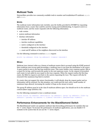
![IP Multicast Routing
In addition, you can modify the backplane load-sharing policy for more robust support of multicast
streams.
NOTE
The round-robin algorithm is not supported on non-“i” series I/O modules. The default backplane
loadsharing policy is “port-based”.
To configure the switch backplane load-sharing policy, use this command:
configure backplane-ls-policy [address-based | port-based | round-robin]
NOTE
For more information on load sharing, see Chapter 4.
Configuring IP Multicasting Routing
To configure IP multicast routing, you must do the following:
1 Configure the system for IP unicast routing.
2 Enable multicast routing on the interface using the following command:
enable ipmcforwarding {vlan <vlan name>}
3 Enable DVMRP or PIM on all IP multicast routing interfaces using one of the following commands:
configure dvmrp add vlan [<vlan name> | all]
configure pim add vlan [<vlan name> | all] {dense | sparse}
4 Enable DVMRP or PIM on the router using one of the following commands:
enable dvmrp rxmode vlan [<vlan name> | all] or enable dvmrp txmode vlan [vlan
<vlan name> | all]
enable pim
448 ExtremeWare 7.2.0 Software User Guide](https://image.slidesharecdn.com/extremewareuserguide72-110124002726-phpapp01/85/Extreme-wareuserguide72-448-320.jpg)
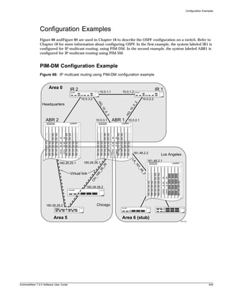
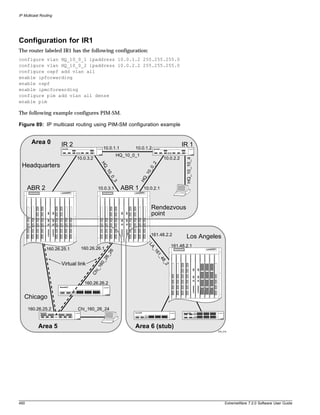
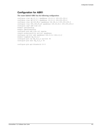

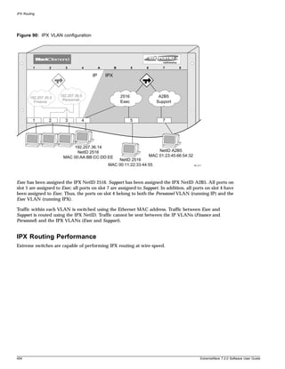
![Overview of IPX
IPX Load Sharing
ExtremeWare supports IPX load sharing on all products that use the “i” chipset. No additional
configuration is required to support this function, simply configure load sharing as you would
normally.
NOTE
For more information on load sharing, see Chapter 4.
IPX Encapsulation Types
Novell NetWare™ supports four types of frame encapsulation. The ExtremeWare term for each type is
described in Table 58.
Table 58: IPX Encapsulation Types
Name Description
ENET_II The frame uses the standard Ethernet 2 header.
ENET_8023 The frame includes the IEEE 802.3 length field, but does not include the IEEE 802.2 Logical
Link Control (LLC) header. This encapsulation is used by NetWare version 2.x and the
original 3.x version.
ENET_8022 The frame uses the standard IEEE format and includes the IEEE 802.2 LLC header. This
encapsulation is used by NetWare version 3.12 and 4.x.
ENET_SNAP The frame adds a Subnetwork Access Protocol (SNAP) header to the IEEE 802.2 LLC
header.
To configure a VLAN to use a particular encapsulation type, use the following command:
configure vlan <vlan name> xnetid <netid> [enet_ii | enet_8023 | enet_8022 |
enet_snap]
Tagged IPX VLANs
ExtremeWare supports tagged 802.1Q traffic on an IPX VLAN that is performing routing. Tagging is
most commonly used to create VLANs that span multiple switches. Using VLAN tags, multiple VLANs
can span multiple switches using one or more trunks. In a port-based VLAN, each VLAN requires its
own pair of trunk ports.
Another benefit of tagged VLANs is the ability to have a port be a member of multiple VLANs. This is
particularly useful if you have a device (such as a server) that must belong to multiple VLANs. A single
port can be a member of only one port-based VLAN. All additional VLAN memberships for that port
must be configured with tags.
To configure a tagged IPX VLAN, assign a tag to the VLAN using the following command:
configure vlan <vlan name> tag <vlan tag>
The valid range is from 1 to 4095.
To assign tagged ports to the VLAN, use the following command:
configure vlan <vlan name> add ports <portlist> {tagged | untagged} {nobroadcast}
{soft-rate-limit}
ExtremeWare 7.2.0 Software User Guide 455](https://image.slidesharecdn.com/extremewareuserguide72-110124002726-phpapp01/85/Extreme-wareuserguide72-455-320.jpg)
![IPX Routing
To display your VLAN settings, use the following command:
show vlan {<vlan name> | detail | stats {vlan} <vlan name>}}
Populating the Routing Table
The switch builds and maintains an IPX routing table. As in the case of IP, the table is populated using
dynamic and static entries.
Dynamic Routes
Dynamic routes are typically learned by way of IPX/RIP. Routers that use IPX/RIP exchange
information in their routing tables in the form of advertisements. Using dynamic routes, the routing
table contains only networks that are reachable.
Dynamic routes are aged out of the table when an update for the network is not received for a period of
time, as determined by the routing protocol.
Static Routes
Static routes are manually entered into the routing table. Static routes are used to reach networks not
advertised by routers. You can configure up to 64 static IPX routes on the switch. Static routes are never
aged out of the routing table. Static routes are advertised to the network using IPX/RIP.
IPX/RIP Routing
The switch supports the use of IPX/RIP for unicast routing. IPX/RIP is different from IP/RIP. However,
many of the concepts are the same. ExtremeWare supports the following IPX/RIP features:
• Split horizon
• Poison reverse
• Triggered Updates
Route information is entered into the IPX route table in one of the following two ways:
• Dynamically, by way of RIP
• Statically, using the command:
configure ipxroute add [<dest_netid> | default] <next_hop_id> <next_hop_node_addr>
<hops> <tics>
IPX/RIP is automatically enabled when a NetID is assigned to the VLAN. To remove the advertisement
of an IPX VLAN, use the command:
configure ipxrip delete vlan [<vlan name> | all]
456 ExtremeWare 7.2.0 Software User Guide](https://image.slidesharecdn.com/extremewareuserguide72-110124002726-phpapp01/85/Extreme-wareuserguide72-456-320.jpg)
![Configuring IPX
GNS Support
ExtremeWare supports the Get Nearest Server (GNS) reply function. When a NetID is assigned to the
switch, the GNS reply service is automatically enabled. When a station requests a particular service on
the network (for example, locating a print server), the station sends a GNS request and the switch
responds to the request. If GNS-reply is disabled, the switch drops the request.
To disable GNS-reply, use the following command:
disable ipxsap gns-reply {vlan <vlan name>}
Routing SAP Advertisements
The switch contains an IPX Service Table, and propagates SAP advertisements to other IPX routers on
the network. Each SAP advertisement contains the following:
• Service type
• Server name
• Server NetID
• Server node address
The service information is entered into the IPX Service Table in one of the following two ways:
• Dynamically, by way of SAP
• Statically, using the following command:
configure ipxservice add <service_type> <service_name> <netid> <mac_address>
<socket> <hops>
Configuring IPX
This section describes the commands associated with configuring IPX, IPX/RIP, and IPX/SAP on the
switch. To configure IPX routing, follow these steps:
1 Create at least two VLANs.
2 If you are combining an IPX VLAN with another VLAN on the same port(s), you must use a
protocol filter on one of the VLANs, or use 802.1Q tagging.
3 Assign each VLAN a NetID and encapsulation type using the following command:
configure vlan <vlan name> xnetid <netid> [enet_ii | enet_8023 | enet_8022 |
enet_snap]
Ensure that each VLAN has a unique IPX NetID and that the encapsulation type matches the VLAN
protocol.
Every IPX VLAN has an internal VLAN ID that is created automatically. Every MAC address
learned from the port associated with the IPX VLAN has two forwarding database (FDB) entries:
— external VLAN ID entry
— internal VLAN ID entry
Once you configure the IPX VLAN information, IPX forwarding automatically begins to function.
Specifically, configuring the IPX VLAN automatically enables the IPX/RIP, IPX/SAP, and SAP GNS
services.
ExtremeWare 7.2.0 Software User Guide 457](https://image.slidesharecdn.com/extremewareuserguide72-110124002726-phpapp01/85/Extreme-wareuserguide72-457-320.jpg)
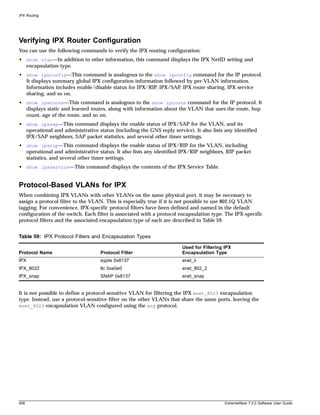
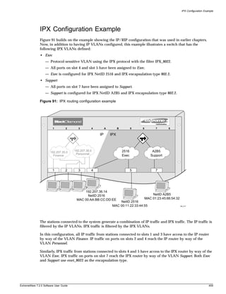


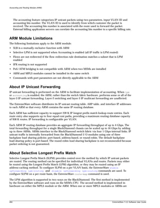
![Summary of Features
installed and active, LPM processing is performed on those modules. Packets destined to VLANs or
routes that are configured for LPM are forwarded to the MPLS modules or ARMs for processing when
SLPM is enabled. The term for packets forwarded in this manner is “LPM routing.”
The IP address-caching method is implemented in hardware on both the MSM and many of the I/O
modules. On Extreme Networks products, this IP address cache is called the IP Forwarding Database
(IP FDB). Packets destined to VLANs or routes that are not configured for LPM routing will not be sent
to the MPLS module or ARM for processing. The term for packets forwarded in this manner is “IP host
routing.” The default forwarding behavior for IP unicast packets is IP host routing.
Due to the nature of the IP FDB, the overall system performance can suffer under adverse conditions.
Under heavy traffic loads with a large number of destination IP addresses, updating IP FDB entries can
tax the system's CPU resources. Similarly, network topology changes can cause large numbers of IP FDB
entries to be added or deleted, taxing the system's CPU. Enabling LPM routing can allow forwarding
decisions for one or more traffic flows to bypass the IP FDB and reduce the load on the CPU.
SLPM, when enabled, also augments the performance of “slow path” forwarding. Under normal
circumstances, if an IP packet received by the system has a destination IP address that cannot be found
in the IP FDB, the CPU must forward that packet. Inserting an MPLS module or ARM, and enabling
SLPM allows slow path processing to be performed by the module's hardware at a greatly accelerated
rate.
The choice of when to configure LPM routing versus IP host routing depends on two criteria:
• The ratio of destination IP addresses to IP routes.
• Bandwidth requirements for IP traffic flows.
When the ratio of destination IP addresses to IP routes is extremely high, as is usually the case for a
switch connected to the Internet, LPM routing should be considered. Typically, LPM routing would be
enabled for any VLAN containing ports that connect to the Internet. However, LPM routing can be
beneficial in any circumstance where the number of IP addresses in a destination network greatly
exceeds the number of routes being advertised by that network. For example, LPM routing could be
enabled for a network consisting mainly of end-user computers or one consisting of dial-up customers.
The amount of bandwidth required by specific IP traffic flows needs to considered as well. LPM routing
is performed by hardware on the MPLS modules or ARMs installed in the system. Each module is
capable of processing 4 Gbps of traffic at maximum, and a maximum of four modules can be installed.
This places an upper limit of 16 Gbps of throughput for traffic being LPM routed. If the aggregate
bandwidth for a set of IP traffic flows exceeds the LPM routing bandwidth, then IP host routing should
be used. An example where IP host routing is beneficial is a core router connecting multiple campus
networks to each other.
A special set of commands is used to configure the SLPM function. Table describes the commands
added to the ExtremeWare software for configuring SLPM.
Table 60: SLPM Commands
Command Description of Change
configure iproute route-map [bgp Configures how the specified route map is to be applied to IP routing tables. If
| direct | e-bgp | i-bgp | ospf | none is selected, it disassociates the route map from the routing protocol.
ospf-extern1 | ospf-extern2 |
ospf-inter | ospf-intra | rip | static]
[<route map> | none]
configure route-map <route-map> Configures IP host routing for the specified route map entry.
<sequence-number> [add | delete
] set iphost-routing
ExtremeWare 7.2.0 Software User Guide 465](https://image.slidesharecdn.com/extremewareuserguide72-110124002726-phpapp01/85/Extreme-wareuserguide72-465-320.jpg)
![Accounting and Routing Module (ARM)
Table 60: SLPM Commands (Continued)
Command Description of Change
configure route-map <route-map> Configures LPM routing for the specified route map entry.
<sequence-number> [add | delete
] set lpm-routing
disable ipforwarding lpm-routing Disable the LPM routing feature for the specified VLAN. If no VLAN is
{vlan <vlan name>} specified, LPM routing is disabled for all VLANs except the management
VLAN.
disable lpm Disables the SLPM function.
enable ipforwarding lpm-routing Enables the LPM routing feature for the specified VLAN. If no VLAN is
{vlan <vlan name>} specified, LPM routing is enabled for all VLANs except the management
VLAN.
enable lpm Enables the SLPM function.
show lpm Indicates if SLPM is currently enabled or disabled.
NOTE
SLB, Selective-LPM and DSA are mutually exclusive functions and cannot be simultaneously enabled.
About Destination-Sensitive Accounting
Destination-sensitive accounting (DSA) collects statistics that are maintained for forwarded IP traffic to
support billing on a destination basis. To configure destination-sensitive accounting, a bin number can
be assigned to one or more IP route entries using the ExtremeWare route-map command.
Bin numbers are integers that range from 0-7 and their only intrinsic meaning is to identify a particular
set of accounting statistics. Each bin contains a 64-bit count of the number of packets that have been
forwarded and a 64-bit count of the number of bytes that have been forwarded. When the MPLS/ARM
module forwards an IP packet, the bin number from the forwarding database entry for the IP
destination is used to identify the set of counters to be updated. Packets forwarded to the MSM CPU
are not counted.
Eight unique bins are maintained for each of the possible 4096 VLAN IDs. Logically, the bins are
organized as a two-dimensional array, with the row index being a VLAN ID and the column index
being a bin number. Thus, when an IP frame is forwarded, the input VLAN ID selects the row and the
bin number from the forwarding database entry selects the column. The use of input VLAN ID enables
billing statistics to be maintained on a per customer basis where the VLAN ID identifies the customer.
DSA can run on either an MPLS or ARM module.
You use a special set of commands to configure the accounting function. Table 61 describes the
commands added to the ExtremeWare software for configuring accounting.
Table 61: Accounting Commands
Command Description of Change
clear accounting counters Clears (zeroes out) all of the accounting statistics.
configure iproute route-map Configures how the specified route map is to be applied to IP routing tables. If
[ospf-intra | ospf-inter | none is selected, it disassociates the route map from the routing protocol.
ospf-extern1 | ospf-extern2 | ospf
| rip | static | e-bgp | i-bgp | bgp |
direct] <route-map> | none
466 ExtremeWare 7.2.0 Software User Guide](https://image.slidesharecdn.com/extremewareuserguide72-110124002726-phpapp01/85/Extreme-wareuserguide72-466-320.jpg)
![Configuring the ARM
Table 61: Accounting Commands (Continued)
Command Description of Change
configure route-map <route-map> Configures the accounting bin number to be associated with the specified
<sequence_number> [add | route map entry. The accounting-index value is always set to 1 for
delete] set accounting-index 1 destination-sensitive accounting.
value <bin_number>
disable accounting Disables the destination-sensitive accounting function.
enable accounting Enables the destination-sensitive accounting function.
show accounting {vlan <vlan Displays accounting statistics for the specified VLAN. If no VLAN is specified,
name>}} statistics for all VLANs are displayed.
NOTE
SLB, Selective-LPM and DSA are mutually exclusive functions and cannot be simultaneously enabled.
Configuring the ARM
This section describes the ExtremeWare commands that support the ARM. For hardware installation
information on the BlackDiamond 6800 series switch, see the Extreme Networks Consolidated Hardware
Guide.
NOTE
Documentation for Extreme Networks products is available on the World Wide Web at the Extreme
Networks home page at http://www.extremenetworks.com.
This section includes information on the following topics:
• Basic Accounting Configuration Information on page 467
• Basic SLPM Configuration Information on page 469
• Using Route Maps on page 471
Basic Accounting Configuration Information
This section uses several typical usage and configuration schemes to provide a brief overview of the
accounting configuration process as a general context for the detailed command description sections
that follow.
In the most basic terms, to enable the accounting function, you must enable the accounting feature,
create a customer VLAN ID, enable IP forwarding, and configure the accounting bin using the route
map feature.
You use a special set of commands to configure the accounting function. Due to the redirection of all
incoming IP unicast packets to the ARM, the accounting feature is incompatible with ExtremeWare
Server Load Balancing, and Selective-LPM. These features cannot be enabled simultaneously.
ExtremeWare 7.2.0 Software User Guide 467](https://image.slidesharecdn.com/extremewareuserguide72-110124002726-phpapp01/85/Extreme-wareuserguide72-467-320.jpg)
![Accounting and Routing Module (ARM)
The following sections describe how to create a customer VLAN ID, how to enable and disable IP
forwarding, how to configure the accounting bin, and how to display destination-based accounting
statistics.
Creating Customer VLAN IDs
A unique VLAN ID is used to identify each of your customers. You create a VLAN ID to identify each
customer and retrieve the accounting bin count for that customer. To create a customer VLAN ID, use
the following commands:
create vlan <vlan name>
configure vlan <vlan name> tag <vlan tag>
configure vlan <vlan name> add ports <portlist> {tagged | untagged} {nobroadcast}
{soft-rate-limit}
The name parameter is the name of the VLAN you created.
The vlanid parameter is the number assigned to the VLAN. The valid numerical range for a VLAN ID
is from 1 to 4095.
The portlist parameter specifies one or more ports assigned to the VLAN.
The tagged | untagged keyword configures the ports as tagged or untagged.
The nobroadcast keyword prevents the switch from forwarding broadcast, multicast, and unknown
unicast traffic.
The following command example creates a customer VLAN named acme with a VLAN ID of 100. Ports
1 and 2 in slot 6 are assigned to the VLAN.
create vlan acme
configure vlan acme tag 100
configure vlan acme add ports 6:1-6:2 tagged
See Chapter 6 for more information.
Enabling and Disabling IP Forwarding
ExtremeWare allows IP forwarding to be enabled on a per-VLAN basis. To enable IP forwarding on a
specific VLAN, use the following command:
enable ipforwarding {[broadcast | fast-direct-broadcast | ignore-broadcast]} {vlan
<vlan name>}
The name parameter is the name of the VLAN you created.
The following command example enables IP forwarding on a VLAN named acme:
enable ipforwarding acme
To disable IP forwarding on a specific VLAN, use the following command:
disable ipforwarding {[broadcast | fast-direct-broadcast | ignore-broadcast]} {vlan
<vlan name>}
The following command example disables IP forwarding on a VLAN named acme:
disable ipforwarding acme
468 ExtremeWare 7.2.0 Software User Guide](https://image.slidesharecdn.com/extremewareuserguide72-110124002726-phpapp01/85/Extreme-wareuserguide72-468-320.jpg)
![Configuring the ARM
Displaying SLPM Information
To determine if the SLPM feature has been enabled, use the following command:
show lpm
This command will report if SLPM is enabled or disabled.
The ExtremeWare show vlan and show iproute commands have been modified to indicate which
VLANs and IP route entries have been enabled for LPM routing. A VLAN for which LPM routing has
been enabled will display an “I” (capital “i”) in the flags field of the show vlan command output. An IP
route entry for which LPM routing has been enabled will display a “P” in the flags field of the show
iproute command.
Configuring Access Profiles
The ExtremeWare route-map command is used for configuring LPM routing and assigning accounting
bin numbers to specific destinations. To configure route map access policies, it may be necessary to
define an access profile.
For more information about access profiles, see Chapter 12.
Using Route Maps
Route maps are used to conditionally configure LPM routing and also to conditionally assign
accounting bin numbers to route destinations. Route maps are used in conjunction with the match and
set operations. A match operation specifies a criteria that must be matched. A set operation specifies a
change that is made to the route when the match operation is successful.
Configuring the Accounting Bin Number for Route Map Entry
To configure an accounting bin number associated with a specified route map entry, use the following
command:
configure route-map <route-map> <sequence_number> [add | delete] set accounting-index
1 value <bin_number>
Where the following is true:
• The route-map parameter identifies a particular route map.
• The sequence_number parameter identifies a specific entry in that route map. The sequence number
must be associated with a match statement.
• The set accounting-index 1 value keyword phrase indicates that the following parameter is an
accounting bin number.
• The bin_number parameter is an integer between 0—7, and allows you to define the accounting bin
number.
Configuring the Routing Method for Route Map Entry
To the configure the routing method associated with a specified route map entry, use the following
commands:
configure route-map <route-map> <sequence-number> [add | delete ] set iphost-routing
configure route-map <route-map> <sequence-number> [add | delete ] set lpm-routing
ExtremeWare 7.2.0 Software User Guide 471](https://image.slidesharecdn.com/extremewareuserguide72-110124002726-phpapp01/85/Extreme-wareuserguide72-471-320.jpg)
![Accounting and Routing Module (ARM)
Where the following is true:
• The route-map parameter identifies a particular route map.
• The sequence_number parameter identifies a specific entry in that route map. The sequence number
must be associated with a match statement.
• The set iphost-routing keyword phrase indicates that IP host routing is to be used for IP route
entries matching this route map entry's criteria.
• The set lpm-routing keyword phrase indicates that LPM routing is to be used for IP route entries
matching this route map entry's criteria.
Applying the Route Map to the IP Routing Table
To configure how the specified route map is applied to IP routing table entries, use the following
command:
configure iproute route-map [bgp | direct | e-bgp | i-bgp | ospf | ospf-extern1 |
ospf-extern2 | ospf-inter | ospf-intra | rip | static] [<route map> | none]
Where the following is true:
• The ospf-intra (intra-area), ospf-inter (inter-area), ospf-extern1 (external type 1),
ospf-extern2 (external type 2), ospf, rip, static, e-bgp (exterior gateway protocol), i-bgp
(interior gateway protocol), bgp (border gateway protocol), and direct (directly connected subnets)
are keywords that identify route sources that are inserted into the IP routing table.
The configured route map is applied when routes of the specified source type are entered into the
routing table. If there is a match between a route map entry and routing table entry, then the specified
action is taken. For accounting, the configured bin number is associated with the matching routing table
entry. If there is no match, the bin number 0 is assigned to the routing table entry. For SLPM, the
configured routing method is selected for the matching routing table entry. If there is no match, the
routing method selected will be based on the routing method for the VLAN associated with the routing
table entry's next-hop.
Displaying the Configured Route Maps for the IP Route Table
To display the configured route maps for the IP route table, use the following command:
show iproute route-map
The following command displays the route map associated with each IP route protocol:
show iproute route-map
Route Origin Route-Map
Direct dsb1
Static dsb1
OSPFIntra dsb2
OSPFInter dsb2
RIP dsb1
OSPFExt1 dsb2
OSPFExt2 dsb2
EBGP dsb2
472 ExtremeWare 7.2.0 Software User Guide](https://image.slidesharecdn.com/extremewareuserguide72-110124002726-phpapp01/85/Extreme-wareuserguide72-472-320.jpg)
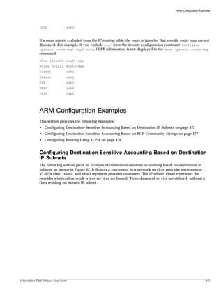
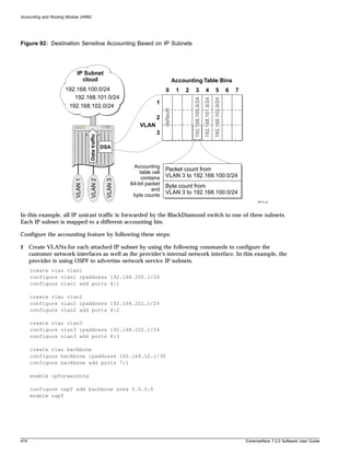
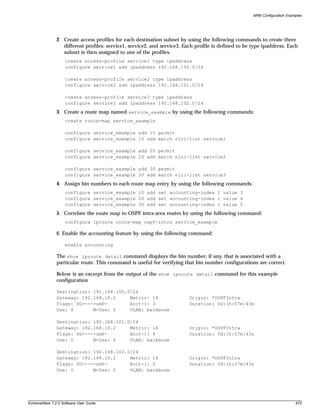
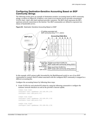
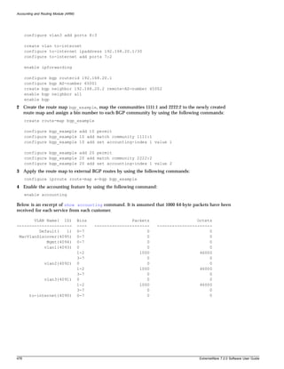
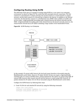
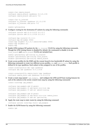
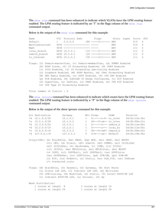
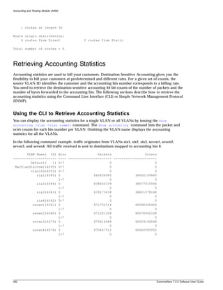
![Diagnostics Commands
Using SNMP to Retrieve Accounting Statistics
Any network manager running SNMP can retrieve accounting statistics provided the Management
Information Base (MIB) is installed correctly on the management station. Each network manager
provides its own user interface to the management facilities. With support for the
CISCO-BGP-POLICY-ACCOUNTING-MIB, you can retrieve accounting statistics using SNMP.
For information about the CISCO-BGP-POLICY-ACCOUNTING-MIB:
1 Go to http://www.cisco.com/public/mibs.
2 Select SNMP v2 MIBs.
3 Select CISCO-BGP-POLICY-ACCOUNTING-MIB.my for information about the MIB.
In this MIB, the accounting statistics are indexed using the following commands:
• interface index ( ifIndex)
• traffic index ( cbpAcctTrafficIndex)
To map a VLAN ID to an interface index, use the interface index of the router interface on the VLAN.
The accounting bin number corresponds directly to the traffic index.
Refer to your SNMP Manager documentation for information on how to load MIBs for use within the
network manager.
Diagnostics Commands
The show diag slot <slot> iproute command displays the ARM IP routing table. The ARM IP
routing table is similar to the IP routing table maintained on the MSM module, but differs in the
following ways:
• A maximum of four equal cost routes are stored.
• Directly attached hosts are inserted into the ARM IP routing table as host routes (OR=ho).
The following commands display the ARM IP routing table:
show diag slot <slot> iproute [origin | summary | <ipaddress>]
show diag slot <slot> iproute origin [bgp | blackhole | direct | e-bgp | best-route |
i-bgp | ospf-extern1 | ospf-extern2 | ospf-inter | ospf-intra | rip | static]
Below is an example of the show diagnostics slot <slot number> iproute command:
GWay VLAN
OR Destination Gateway Gateway MAC Flags VLAN Acct Flags
d 192.168.20.0/30 192.168.20.1 000130032000 mf_L to-internet 0 _____
d 192.168.10.0/30 192.168.10.1 000130032000 mf_L backbone 0 _____
d 192.168.200.0/24 192.168.200.1 000130032000 mf_L vlan1 0 _____
d 192.168.201.0/24 192.168.201.1 000130032000 mf_L vlan2 0 _____
d 192.168.202.0/24 192.168.202.1 000130032000 mf_L vlan3 0 _____
ho 192.168.10.2/32 192.168.10.2 00a2f1000001 mf__ backbone 0 f_urt
ho 192.168.20.2/32 192.168.20.2 00a2f2000001 mf__ to-internet 0 f_urt
be 192.168.52.0/24 192.168.20.2 00a2f2000001 mf__ to-internet 1 f_urt
be 192.168.53.0/24 192.168.20.2 00a2f2000001 mf__ to-internet 2 f_urt
ExtremeWare 7.2.0 Software User Guide 483](https://image.slidesharecdn.com/extremewareuserguide72-110124002726-phpapp01/85/Extreme-wareuserguide72-483-320.jpg)
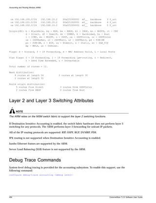
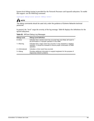

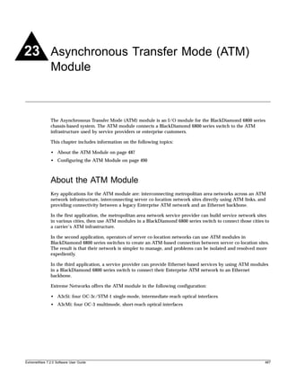
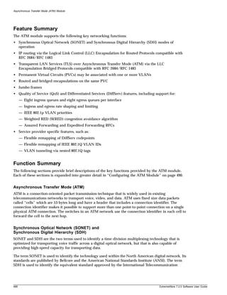
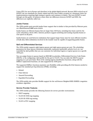
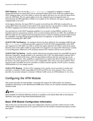
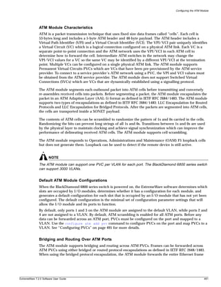
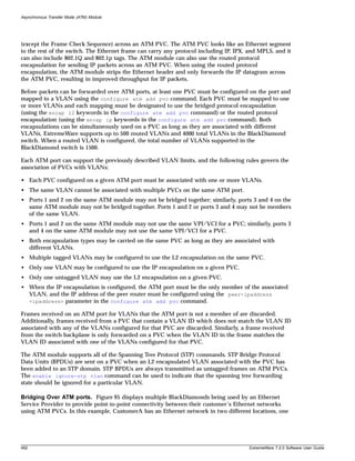
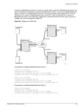
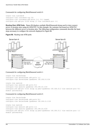
![Configuring and Monitoring ATM Ports
Configuring and Monitoring ATM Ports
This section describes the commands used to configure ATM ports and provides information on the
following topics:
• Configuring PVCs on page 495
• Deleting PVCs on page 495
• Displaying ATM Port Status Information on page 496
• Displaying PVC Status Information on page 497
• Configuring ATM Scrambling on page 497
Configuring PVCs
This section describes how to configure a PVC on an ATM port.
The following command is used to define a PVC on an ATM port:
configure atm add pvc <vpi/vci> encap [l2 | ip peer-ipaddress <ipaddress>] vlan <vlan
name> ports <portlist>
Where the following is true:
• The PVC is identified by the specified vpi and vci parameters. The vpi parameter is an integer in
the range of 0 through 15. The vci parameter is an integer in the range of 17 through 4095.
• The encap parameter indicates the type of encapsulation that is to be used on the PVC for traffic
from the associated VLAN. The l2 keyword is an abbreviation for Layer-2 and indicates the LLC
Encapsulation for Bridged Protocols (defined in RFC 2684). The ip keyword indicates that the VLAN
will carry only routed IP traffic and that the LLC Encapsulation for Routed Protocols (defined in
RFC 2684) should be used.
Deleting PVCs
The following command is used to delete a PVC configuration on an ATM port:
configure atm delete pvc [<vpi / vci> | all] {vlan <vlan name>} ports <portlist>
This command deletes the specified PVC configuration on the specified ATM port(s). The optional vlan
parameter may be used to limit the scope of the command to the specified VLAN. The PVC may still
exist following command execution if multiple VLANs have been configured to use the PVC. If the
vlan parameter is omitted, the PVC configuration is deleted for all VLANs on the specified ATM
port(s).
The command can be used to delete configuration information for the PVC identified via the vpi and
vci parameters for all PVCs defined for the specified VLAN(s) or port(s). The all keyword may also be
used as the portlist parameter to indicate that the command should be applied to all ATM ports. A PVC
is completely deleted when there are no longer any VLANs configured for the PVC on a given ATM
port.
NOTE
All associated PVCs must be deleted before an ATM port can be removed from a VLAN.
ExtremeWare 7.2.0 Software User Guide 495](https://image.slidesharecdn.com/extremewareuserguide72-110124002726-phpapp01/85/Extreme-wareuserguide72-495-320.jpg)
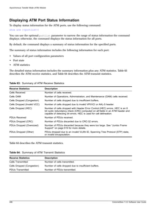
![Configuring and Monitoring ATM Ports
Displaying PVC Status Information
To display status information for a PVC, use the following command:
show atm [<vpi / vci> | all] {vlan <vlan name>} ports <portlist>
You can specify a particular PVC to display information for, or you can specify that information for all
PVCs be displayed.
You can use the optional vlan parameter to narrow the range of status information the command
displays; otherwise, the command displays status information for all VLANs.
You can use the optional portlist parameter to narrow the range of status information the command
displays; otherwise, the command displays the status information for all PVCs associated with all ATM
ports.
By default, the command displays a summary of status information for the specified PVC.
The summary of status information includes the following information for each PVC:
• Port number
• VPI/VCI
• VLAN IDs on this PVC
• Type of PVC (L2 or IP)
• Peer IP address (for IP PVCs)
• Received octets
• Received packets
• Transmitted octets
• Transmitted packets
The following command example displays all of the PVC status information for a PVC configured on an
ATM port in a BlackDiamond switch:
show atm pvc 5/101 port 1:1
Configuring ATM Scrambling
To enable or disable payload data scrambling on the specified port, use the following command:
configure atm scrambling [on | off] ports <portlist>
Choose either on or off. Scrambling is enabled by default.
Scrambling is used to improve signal synchronization and the performance of the ATM cell delineation
process.
The following command example turns off the scrambling function for port 1 of the ATM module
installed in slot 8 of the BlackDiamond switch.
configure atm scrambling off ports 8:1
ExtremeWare 7.2.0 Software User Guide 497](https://image.slidesharecdn.com/extremewareuserguide72-110124002726-phpapp01/85/Extreme-wareuserguide72-497-320.jpg)
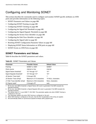
![Configuring and Monitoring SONET
Configuring SONET Framing
You can configure each port for framing that complies with either the SONET standard or the SDH
standard. SONET is primarily an American standard; SDH is the international version. The default is
SONET.
To configure the framing for the specified SONET feature on an ATM port, use the following command:
configure sonet framing [sonet | sdh] ports <portlist>
The following command example selects SDH framing for port 1 of the ATM module installed in slot 8
of the BlackDiamond switch.
configure sonet framing sdh ports 8:1
Configuring SONET Clocking
You can configure each port on the ATM module to use either line clocking, where the clock source is
recovered from the received bit stream, or internal clocking, where the clock source is based on an
internal clock. The default is internal.
To configure the clocking source for the specified ATM port, use the following command:
configure sonet clocking [line | internal] ports <portlist>
The following command example selects line clocking for port 1 of the ATM module installed in slot 8
of the BlackDiamond switch.
configure sonet clocking line ports 8:1
Configuring the Signal Fail Threshold
A Signal Failure (SF) event is generated if the bit error rate (BER) for the SONET line exceeds the
configured threshold. An SF event brings the port down.
To configure the Signal Fail threshold for the specified ATM port, use the following command:
configure sonet threshold signal fail <error_rate> ports <portlist>
The error_rate parameter is an integer in the range from 3 to 5, where the SF BER is 10-error_rate. The
default value of the error_rate parameter is 5, which equates to an SF bit error rate of 10-5, or 1 per
hundred thousand.
The following command example sets the Signal Fail threshold value to 3 for port 1 of the ATM module
installed in slot 8 of the BlackDiamond switch.
configure sonet threshold signal fail 3 ports 8:1
NOTE
You can set the signal fail threshold to a value different than the default value of 5 if your particular
application has a very low tolerance for errors. In general, you should not change the default setting
unless you are an expert and have a specific reason for the change.
ExtremeWare 7.2.0 Software User Guide 499](https://image.slidesharecdn.com/extremewareuserguide72-110124002726-phpapp01/85/Extreme-wareuserguide72-499-320.jpg)
![Asynchronous Transfer Mode (ATM) Module
Configuring the Signal Degrade Threshold
A Signal Degrade (SD) event is generated if the BER for the SONET line exceeds the configured Signal
Degrade threshold.
To configure the Signal Degrade threshold for the specified ATM port, use the following command:
configure sonet threshold signal degrade <error_rate> ports <portlist>
The error_rate parameter is an integer in the range from 5 to 9, where the SD bit error rate is
10-error_rate. The default value of the error_rate parameter is 6, which equates to an SD bit error rate of
10-6, or 1 per million.
The following command example sets the Signal Degrade threshold value to 8 for port 1 of the ATM
module installed in slot 8 of the BlackDiamond switch.
configure sonet threshold signal degrade 8 ports 8:1
NOTE
You can set the signal degrade threshold to a different value than the default value of 6 depending on
your particular application’s tolerance for errors. In general, you should not change the default setting
unless you are an expert and have a specific reason for the change.
Configuring the Section Trace Identifier
Section trace is a maintenance feature of SONET. One byte of the Section Overhead associated with each
SONET frame is used to carry information identifying the transmitting equipment.
To configure the Section Trace identifier for the specified ATM port, use the following command:
configure sonet trace section [<id_byte> | string <id_string>] ports <portlist>
In this command, the Section Trace identifier can take one of two forms: an ID byte (id_byte) or an ID
string (id_string).
The id_byte parameter is an integer in the range from 1 to 255, with a default value of 1. This
parameter applies only when SONET framing is configured, in which case, the configured id_byte
value is transmitted in each SONET frame.
The id_string parameter is a string of up to 15 characters. By default, the <id_string> parameter
contains 15 NULL characters. This parameter applies only when SDH framing is configured, in which
case the SDH framing cycles repetitively through a 15-character string, sending one character per frame.
If the configured string contains fewer than 15 characters, it is padded to full length by NULL
characters.
500 ExtremeWare 7.2.0 Software User Guide](https://image.slidesharecdn.com/extremewareuserguide72-110124002726-phpapp01/85/Extreme-wareuserguide72-500-320.jpg)
![Configuring and Monitoring SONET
The following command example sets the Section Trace identifier to the string “1800wombat” for port 1
of the ATM module installed in slot 8 of the BlackDiamond switch:
configure sonet trace section string 1800wombat ports 8:1
Configuring the Path Trace Identifier
Path trace is a maintenance feature of SONET. One byte of the Path Overhead associated with each
SONET frame is used to carry information identifying the originating Path Terminating Equipment
(PTE).
To configure the Path Trace identifier for the specified ATM port, use the following command:
configure sonet trace path <id_string> ports <portlist>
The id_string parameter defaults to a string of 62 NULL characters.
When SONET framing is configured, a 62-character string is transmitted repetitively, one character per
frame. If the configured string consists of fewer than 62 characters, it is padded to its full length with
NULL characters.
When SDH framing is configured, the maximum length of the id_string parameter is 15 characters. If
the configured string consists of more than 15 characters, it is truncated to 15 characters.
The following command example sets the Path Trace identifier to the string “parador” for port 1 of the
ATM module installed in slot 8 of the BlackDiamond switch.
configure sonet trace path parador ports 8:1
Configuring the Signal Label
The Signal Label field occupies one byte (C2) of the Path Overhead associated with each SONET frame.
It is used to indicate the type of contents carried in the Synchronous Payload Envelope (SPE). For
example, 0x13 indicates that the SONET SPE contains ATM cells.
To configure the C2 Signal Label value for the specified ATM port, use the following command:
configure sonet signal label [auto | <hex_octet>] ports <portlist>
The hex_octet parameter is specified as a hexadecimal integer in the range from 00 to FF. It may be
necessary to specify a particular Signal Label value in order to interoperate with implementations that
do not follow the standard conventions for the Signal Label field.
To determine whether you need to specify a particular Signal Label value, perform the following tasks:
1 Use the show sonet command to display SONET status information on ATM ports.
2 Look for a Path Payload Label Mismatch (PLM-P) event indicating that the received payload type
does not match the expected payload.
3 Compare the contents of the received C2 field (Signal Label value) with the contents of the
transmitted C2 field.
If no Signal Label value is specified, the command defaults to auto, which causes the value of the
Signal Label field to be set automatically based on standard conventions for the given payload type.
ExtremeWare 7.2.0 Software User Guide 501](https://image.slidesharecdn.com/extremewareuserguide72-110124002726-phpapp01/85/Extreme-wareuserguide72-501-320.jpg)
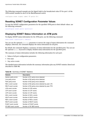
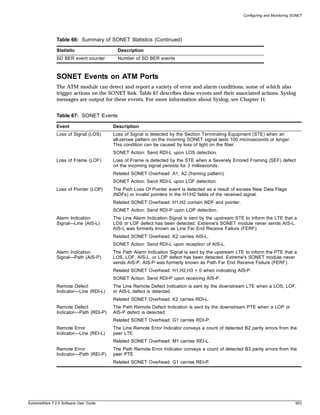
![Asynchronous Transfer Mode (ATM) Module
Table 67: SONET Events (Continued)
Event Description
Path Payload Label The Path Payload Label Mismatch event occurs when the received payload type does
Mismatch (PLM-P) not match the expected payload. This event is commonly caused by a Signal Label or
scrambling mode mismatch configuration error.
Related SONET Overhead: C2 carries the Signal Label.
Signal Failure Bit Error The Signal Failure BER event occurs when the B2 bit error rate exceeds the configured
Rate (SF BER) SF threshold.
Related SONET Overhead: B2 carries line parity.
SONET Action: Send RDI-L upon detecting SF BER event.
Signal Degrade Bit Error The Signal Degrade BER event occurs when the B2 bit error rate exceeds the
Rate (SD BER) configured SD threshold. This event is used for APS switching.
Related SONET Overhead: B2 carries line parity.
Configuring VLAN-Related Attributes
The ExtremeWare software and the Extreme Networks switch architecture provide a range of Virtual
Local Area Network (VLAN) features. This section describes how these features are supported on the
ATM module.
NOTE
This section assumes some familiarity with the Extreme Networks implementation of VLAN features. For
more information about VLAN-related features supported by ExtremeWare, see Chapter 6, “Virtual LANs
(VLANs)” on page 115.
This section provides information on the following topics:
• Configuring Tagged VLAN 802.1p and 802.1Q Functions on page 505
• Generic VLAN Registration Protocol Functions on page 507
ATM module ports do not support protocol-based VLANs or MAC address VLANs. Thus, there are
restrictions on the use of the following commands:
• configure vlan <vlan name> add ports <portlist> {tagged | untagged} {nobroadcast}
{soft-rate-limit}
• configure vlan <vlan name> delete port <portlist>
• configure vlan <vlan name> protocol [<protocol_name> | any]
• enable mac-vlan mac-group [any | <group_number>] port <portlist>
504 ExtremeWare 7.2.0 Software User Guide](https://image.slidesharecdn.com/extremewareuserguide72-110124002726-phpapp01/85/Extreme-wareuserguide72-504-320.jpg)
![Configuring VLAN-Related Attributes
The restrictions are as follows:
• An ATM port cannot be added to a VLAN if the VLAN is a protocol-based VLAN.
• A VLAN cannot be configured to be a protocol-based VLAN if the VLAN contains an ATM port.
• A MAC address VLAN cannot be enabled on an ATM port.
The configure vlan <vlan name> protocol [<protocol_name> | any] command is supported,
because it can be used to configure the default VLAN for ATM ports.
In the configure vlan <vlan name> add ports <portlist> {tagged | untagged}
{nobroadcast} {soft-rate-limit} command, ATM ports support the optional tagged and
untagged keywords when LLC encapsulation for bridged protocols is enabled, and ignore them when
LLC encapsulation for routed protocols is enabled.
Configuring Tagged VLAN 802.1p and 802.1Q Functions
NOTE
The dot1q tag mapping and tag nesting commands are supported only by ATM ports and apply only
when LLC encapsulation for bridged protocols is enabled on the ATM port.
The following ExtremeWare commands are supported for the ATM module:
• configure dot1q ethertype <ethertype>
• configure dot1p type <dot1p_priority> qosprofile <qosprofile>
NOTE
If an ATM port receives a frame with a priority value “n” that is not mapped to a profile in the range from
qp1 through qp8, the frame is assigned to QoS profile qpn+1.
The following commands provide ATM module support for managing 802.1Q tags:
• configure dot1q tagmapping <input_vlanid/output_vlanid> ports <portlist> {egress
{priority <priority>} | ingress {priority <priority>}}
• configure dot1q tagnesting {<vlanid> | <vlanid_range>} [off | pop | push
<new_vlanid> {priority <priority>}] ports <portlist> {egress | ingress}
Configuring VLAN Tag Mapping Tables
The configure dot1q tagmapping ports command provides support for VLAN ID (VID) mapping
tables. Each ATM port supports two VID tables: one table is used in the ingress direction; the other is
used in the egress direction. These tables make it possible to map an input VID to an output VID, which
can be useful in reconciling policy differences at the boundary between the customer and the service
provider. The tables also allow the option of preserving the 802.1p priority or overwriting the priority
with a configured value.
To configure the VLAN tag mapping tables for an ATM port, use the following command:
configure dot1q tagmapping <input_vlanid/output_vlanid> ports <portlist> {egress
{priority <priority>} | ingress {priority <priority>}}
ExtremeWare 7.2.0 Software User Guide 505](https://image.slidesharecdn.com/extremewareuserguide72-110124002726-phpapp01/85/Extreme-wareuserguide72-505-320.jpg)
![Asynchronous Transfer Mode (ATM) Module
The input_vlanid and output_vlanid parameters are both integers in the range from 1 to 4095 and
must be separated by a slash character.
The priority parameter is an integer in the range from 0 to 7.
Use the egress keyword to apply the mapping of the input VLAN ID to the output VLAN ID to frames
received from the switch backplane prior to transmitting them onto the ATM link. Use the ingress
keyword to apply the mapping to input frames received from the ATM link. The mappings are applied
after they are classified to a QoS profile. Frames containing the VLAN ID specified in input_vlanid are
changed so that the VLAN ID is set to the value specified in output_vlanid before the frame is
forwarded.
If you omit both the egress and the ingress keywords, the command automatically applies the
specified mapping to the egress direction, and also applies a symmetrical mapping (with the
input_vlanid and output_vlanid values reversed) to the ingress direction.
These tables also give you the option of preserving the 802.1p priority or overwriting the priority with a
user-configured value. Using the priority keyword in the command indicates that the 802.1p priority
field is to be set to the value specified in priority. To preserve the 802.1p priority, do not enter the
priority keyword and value when using this command.
The default behavior is that the tables are initialized such that VLAN IDs are not altered by the
mapping operations, and frame priority is preserved. For example, an input VLAN ID of n is always
mapped to an output VLAN ID of n, and the 802.1p priority field is not changed.
Configuring VLAN Tag Nesting Attributes
The configure dot1q tagnesting command provides support for 802.1Q tags by allowing a tag push
or pop attribute to be associated with a VLAN ID. The push attribute indicates that a new tag is to be
added to the frame, while the pop attribute indicates that the top-level tag is to be removed from the
frame. The command also gives you the option to preserve the 802.1p priority of the frame or set it to a
configured value when a new tag is added (pushed) to the frame. VLAN ID (VID) mapping occurs
before a new tag is pushed, and after a nested tag is popped.
To configure the VLAN tag nesting attributes for an ATM port, use the following command:
configure dot1q tagnesting {<vlanid> | <vlanid_range>} [off | pop | push <new_vlanid>
{priority <priority>}] ports <portlist> {egress | ingress}
The vlanid parameter is an integer in the range from 1 to 4095. The vlanid_range parameter is
specified in the form start_vlanid-end_vlanid, where the start and end values are both integers in the
range from 1 to 4095 and must be separated by a hyphen.
The push keyword indicates that a new tag is to be added to frames containing the VID specified in
vlanid or to one of the VIDs in the range specified in vlanid_range. The new tag added to frames
contains the value specified in new_vlanid.
The pop keyword indicates that the top-level tag is to be removed from frames when that tag contains
either the VID specified in vlanid or any one of the VIDs in the range specified in vlanid_range.
If you do not specify a VID or a range of VIDs, the command settings are applied to all VIDs.
Tag operations can be performed in either the egress direction (to the ATM link) or the ingress direction
(from the ATM link). If you do not specify a direction, the default behavior is that tag operations are
performed in the egress direction. If you do not use either the egress or ingress keyword and tag
pushing is configured, a corresponding tag pop operation is automatically configured for the ingress
506 ExtremeWare 7.2.0 Software User Guide](https://image.slidesharecdn.com/extremewareuserguide72-110124002726-phpapp01/85/Extreme-wareuserguide72-506-320.jpg)
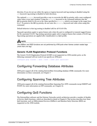
![Asynchronous Transfer Mode (ATM) Module
NOTE
This section assumes some familiarity with the Extreme Networks implementation of QoS and DiffServ
features. For more information about QoS and DiffServ features supported by ExtremeWare, see
Chapter 8.
This section contains information on the following topics:
• Configuring a QoS Profile on page 508
• Classification and Replacement Policies on page 509
• Configuring DiffServ on page 510
• Enhanced RED Support on page 512
Configuring a QoS Profile
The ATM module supports eight ingress queues and eight egress queues per port. The scheduling
parameters (minimum bandwidth, maximum bandwidth and priority level) for these queues are
controlled by QoS profiles qp1 through qp8, which are defined using the existing ExtremeWare
configure qosprofile command.
This command has been enhanced to allow you to configure more module-specific parameters on a
port-by-port basis, including the ability to customize the QoS profile parameters for individual ingress
or egress queues on a specific ATM port.
The syntax and description of the enhanced configure qosprofile command are described below.
To configure the scheduling parameters for a specified QoS profile, use the following command:
configure qosprofile <qosprofile> minbw <min_percent> maxbw <max_percent> priority
<level> {[minbuf <percent> maxbuf <number> [K | M] | maxbuff <number> [K | M] |
<portlist>]}
The optional egress and ingress keywords apply only to ATM ports. As stated earlier, the ATM
module supports eight egress queues and eight ingress queues per port, and the scheduling parameters
for these queues are controlled by QoS profiles qp1-qp8, which means queue #0 is controlled by qp1,
queue #1 is controlled by qp2, and so on.
The optional portlist parameter allows QoS profiles to be customized on a port-by-port basis for the
ATM module. The egress and ingress keywords allow you to fine-tune the customization (down to a
particular egress or ingress queue on a given port). If you do not enter either the egress or ingress
keyword in the command, the configured parameters apply to the egress queue associated with the
specified QoS profile by default.
The minbw parameter specifies the minimum percentage of the bandwidth guaranteed to be available to
the specified queue for transmissions from the QoS profile. The value is an integer in the range from 0
through 100. The default value is 0. The sum of the minimum bandwidth parameters across all eight
QoS profiles cannot exceed 90%.
The maxbw parameter specifies the maximum percentage of the bandwidth that the specified queue can
use for transmissions from the QoS profile. The value is an integer in the range from 1 through 100. The
default value is 100.
508 ExtremeWare 7.2.0 Software User Guide](https://image.slidesharecdn.com/extremewareuserguide72-110124002726-phpapp01/85/Extreme-wareuserguide72-508-320.jpg)
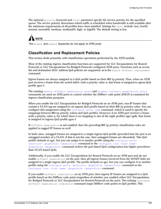
![Asynchronous Transfer Mode (ATM) Module
command has been enhanced for use with ATM ports. The syntax and description of the enhanced
configure diffserv examination code-point qosprofile ports command are given below.
Also note that, in all cases, the 802.1p priority bits of ingress frames forwarded to the switch backplane
are set based on the ingress QoS profile classification. More specifically, the 802.1p priority value is set
to qp# – 1. For example, if the packet is classified to qp5, then the 802.1p priority value is set to 4.
Configuring DiffServ
All of the existing ExtremeWare DiffServ commands are supported by ATM ports with IP frames that
are encapsulated for bridged or routed protocols. ATM ports also support a DiffServ code point (DSCP)
mapping function that you configure using the configure diffserv dscp-mapping command, which
is described below. The DSCP is a 6-bit value in the IP-TOS byte of the IP packet header. For more
information on DSCPs, see Chapter 8.
DiffServ Classification
When a packet arrives at the switch on an ingress port, the switch examines the first six of eight TOS
bits, called the code point. The switch can assign the QoS profile used to subsequently transmit the
packet based on the code point. The QoS profile controls a hardware queue used when transmitting the
packet out of the switch, and determines the forwarding characteristics of a particular code point. The
examination of DiffServ information is disabled by default. To enable examination of DiffServ
information, use the command:
enable diffserv examination ports [<portlist> | all]
Changing DiffServ Code Point Assignments in the QoS Profile
Because the code point uses six bits, it has 64 possible values (26 = 64). By default, the values are
grouped and assigned to the default QoS profiles listed in Table 68.
Table 68: Default Code Point-to-QoS Profile Mapping
Code Point QoS Profile
0-7 Qp1
8-15 Qp2
16-23 Qp3
24-31 Qp4
32-39 Qp5
40-47 Qp6
48-55 Qp7
56-63 Qp8
To configure the mapping between a DiffServ code point and a specified QoS profile, use the following
command:
configure diffserv examination code-point <code_point> qosprofile <qosprofile> ports
[<portlist> | all] {low-drop-probability | high-drop-probability}
The mapping is applied in the ingress direction—for IP packets received from the ATM link.
510 ExtremeWare 7.2.0 Software User Guide](https://image.slidesharecdn.com/extremewareuserguide72-110124002726-phpapp01/85/Extreme-wareuserguide72-510-320.jpg)
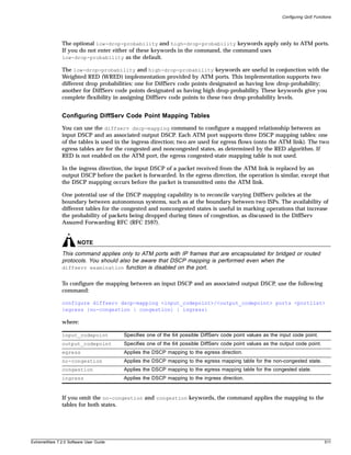
![Asynchronous Transfer Mode (ATM) Module
If you omit the egress and ingress keywords, the command applies the mapping to the egress
direction, and automatically configures a symmetrical mapping (with the input_codepoint and
output_codepoint values reversed) in the ingress direction.
By default, all the tables are initialized such that DSCPs are not altered by the mapping operations. For
example, an input DSCP value of n is always mapped to an output DSCP value of n.
Resetting DiffServ Code Point Mapping Tables
To reset the DSCP mapping tables for a specified ATM port to their default values, use the following
command:
unconfigure diffserv dscp-mapping ports <portlist>
Replacing DiffServ Code Points
To replace DiffServ code points, you must use the following command to enable DiffServ replacement:
enable diffserv replacement ports [<portlist> | all]
You then change the 802.1p priority to DiffServ code point mapping to any code point value using the
following command:
configure diffserv replacement priority <value> code-point <code_point> ports
[<portlist> | all]
By doing so, the hardware queue used to transmit a packet determines the DiffServ value replaced in
the IP packet.
To verify the DiffServ configuration, use the command:
show ports {mgmt | <portlist>} info {detail}
Enhanced RED Support
Random Early Detection (RED) is a congestion avoidance mechanism. The basic idea behind RED is that
most data transports detect packet loss and will, therefore, restrain transmission—if only
temporarily—when they detect dropped packets. Consequently, if the switch needs to signal another
device to slow transmission due to congestion, RED provides a way of intelligently dropping packets.
This section describes the changes and additions to ExtremeWare to support RED in conjunction with
ATM modules that have IP frames encapsulated in bridged or routed protocols. The Extreme
implementation of RED combines the functions of the RED algorithm with IP precedence to provide
support for preferential traffic handling for higher-priority packets. This implementation provides
weighted RED (WRED) functionality through two packet-drop probabilities (described below), so that a
device can selectively drop lower-priority traffic when an interface begins to show signs of congestion.
This capability is combined with DiffServ attributes to allow you to tailor performance characteristics
for different classes of service.
512 ExtremeWare 7.2.0 Software User Guide](https://image.slidesharecdn.com/extremewareuserguide72-110124002726-phpapp01/85/Extreme-wareuserguide72-512-320.jpg)
![Configuring QoS Functions
Configuring RED Drop Probability
To configure the RED drop probability for a specified ATM port, use the following command:
configure red [drop-probability | low-drop-probability | high-drop-probability]
<percent> {ports <portlist>}
The optional low-drop-probability, high-drop-probability, and ports keywords are supported
only for ATM ports.
If you omit the ports keyword, the command applies the setting to all ports.
The drop probability is specified as a percentage, where the percent parameter is an integer in the
range from 1 to 100.
Weighted RED (WRED) functionality is supported through two different drop probabilities: a
low-drop-probability and a high-drop-probability. The DiffServ code points of IP packets indicate
whether the packet should be dropped with low probability or high probability, and the appropriate
percentage is then applied if WRED is active.
NOTE
WRED is applied only to IP packets. The configure diffserv examination code-point command
gives you complete flexibility in assigning DSCPs to the two different drop-probability levels. This
configured mapping of DSCPs to drop-probability levels is used by WRED even if diffserv
examination is disabled on the port.
The drop-probability keyword indicates that the specified percentage should be used for both the
low and high drop-probabilities. This effectively disables WRED and reverts to standard RED operation.
For ATM ports, both the low and high drop-probabilities default to 10%.
The role of the configured drop probability in RED operation on ATM ports is illustrated in Figure 97A.
RED is active when the average queue length is between the minimum and maximum thresholds. In
this region, the probability that a given packet is dropped increases in a straight line up to the
configured drop probability at the maximum threshold. All packets are dropped when the average
queue length exceeds the maximum threshold.
The operation of WRED on ATM ports is depicted in Figure 97B. In this case, the drop probability
depends not only on the average queue length, but also upon whether the DSCP indicates that the
packet should be dropped with a low or high probability, which is to say, the DSCP of the packet
controls which curve is used.
ExtremeWare 7.2.0 Software User Guide 513](https://image.slidesharecdn.com/extremewareuserguide72-110124002726-phpapp01/85/Extreme-wareuserguide72-513-320.jpg)
![Asynchronous Transfer Mode (ATM) Module
Figure 97: Comparisons of RED and WRED operation
A. RED Operation on ATM Ports
100
Packet
Configured drop-probability
drop
probability
0
Minimum Maximum
threshold threshold
Average queue length
B. WRED Operation on ATM Ports
100
Packet
High-drop-probability
drop
probability
Low-drop-probability
0
Minimum Maximum
threshold threshold
Average queue length ATM_010
Enabling and Disabling RED on ATM Ports
The existing ExtremeWare commands to enable and disable RED ports have been enhanced to provide
RED configuration attributes for the ATM module. Because the ATM module supports eight egress
queues per port, the commands were enhanced to allow the user a way to enable RED selectively on an
individual port and queue basis. By default, RED is disabled.
To enable RED on a specified ATM port, use the following command:
enable red ports [mgmt | <portlist>]
To disable RED on a specified ATM port, use the following command:
disable red ports <portlist>
The optional queue keyword applies only to ATM ports. You can use this keyword to enable or disable
the RED function on an individual queue basis.
The queue# parameter is an integer in the range from 0 to 7, and identifies one of the eight egress
queues. If you omit the queue keyword, the command applies to all of the queues for the ATM port.
514 ExtremeWare 7.2.0 Software User Guide](https://image.slidesharecdn.com/extremewareuserguide72-110124002726-phpapp01/85/Extreme-wareuserguide72-514-320.jpg)
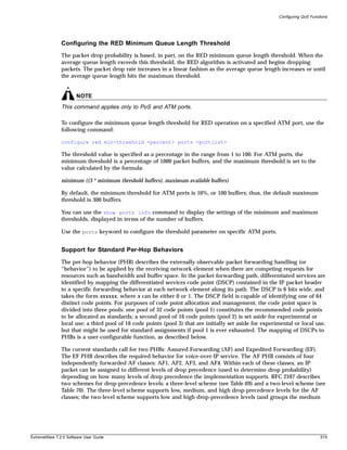
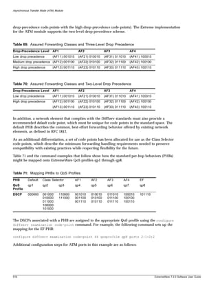
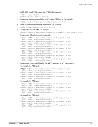
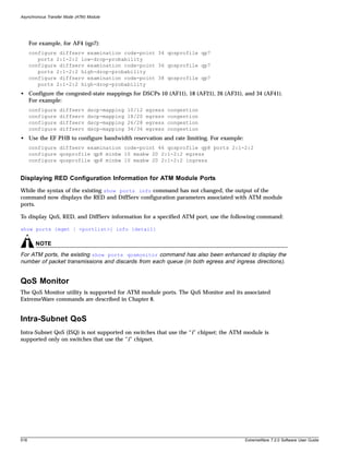
![Limitations and Unsupported Features
Limitations and Unsupported Features
This section describes additional command and configuration information related to the use of the ATM
module. This section includes information on the following topics:
• Configuring Port Attributes on page 519
• Jumbo Frame Support on page 519
• Configuring IGMP Attributes on page 520
• Configuring Layer 2 and 3 Switching Attributes on page 520
• Configuring Access List Attributes on page 520
• Changing Image and Configuration Attributes on page 520
Configuring Port Attributes
The following ExtremeWare port commands are not supported for the ATM module:
• show ports {mgmt | <portlist>} collisions
• configure ports [<portlist> | all | mgmt] auto off {speed [10 | 100 | 1000]}
duplex [half | full]
• configure ports [<portlist> | mgmt | all] auto on
• disable smartredundancy [<portlist>]
• enable sharing <port> grouping <portlist> {dynamic | algorithm {port-based |
address-based | round-robin}}
• enable mirroring to port [<port>] [tagged | untagged]
• disable learning ports <portlist>
• configure mirroring add [<mac_address> | vlan <vlan name> {ports <port number>} |
ports <portnumber> {vlan <vlan name>}]]
Jumbo Frame Support
The jumbo frame size affects the size of the payload that can be transmitted or received on an ATM
port.
If jumbo frame support is enabled on an ATM port, the following can occur:
• No frames received from the switch backplane will be discarded due to being too large. Nor will any
IP frames be fragmented.
• PDUs received from the ATM link with routed protocol encapsulation will be discarded if the size of
the IP packet exceeds (configured JUMBO_FRAME_MTU -22) octets.
• PDUs received from the ATM link with bridged protocol encapsulation will be discarded if the size
of the Ethernet frame (including a VLAN tag but excluding the LAN FCS) exceeds (CONFIGURED
JUMBO_FRAME_MTU - 4) octets. If the Ethernet frame does not include a VLAN tag field, then the
frame will be discarded if the size of the Ethernet frame (excluding the LAN FCS) exceeds
(CONFIGURED JUMBO_FRAME_MTU - 8) octets.
If jumbo frame support is not enabled on an ATM port, the following can occur:
ExtremeWare 7.2.0 Software User Guide 519](https://image.slidesharecdn.com/extremewareuserguide72-110124002726-phpapp01/85/Extreme-wareuserguide72-519-320.jpg)
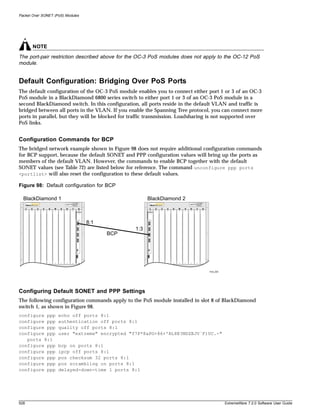
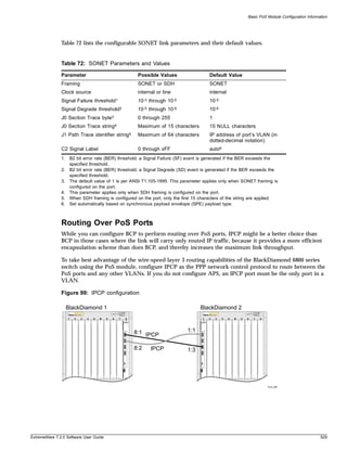
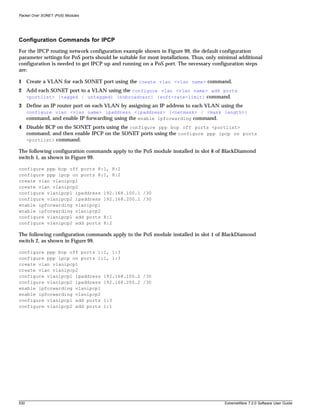
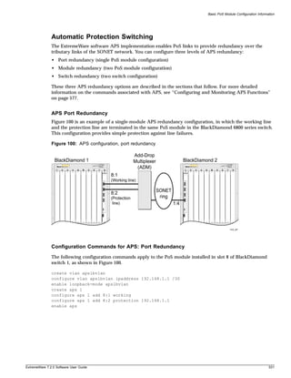
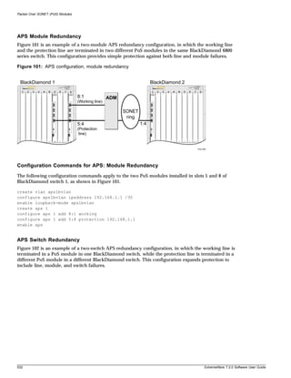
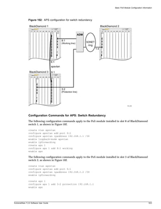
![Configuring and Monitoring SONET Ports
Configuring SONET Clocking
You can configure each port on the PoS module to use either line clocking, where the clock source is
recovered from the received bit stream, or internal clocking, where the clock source is based on an
internal clock. The default is internal.
To configure the clocking source for the specified SONET port, use the following command:
configure sonet clocking [line | internal] ports <portlist>
The following command example selects line clocking for port 1 of the PoS module installed in slot 8 of
the BlackDiamond switch.
configure sonet clocking line ports 8:1
Configuring the Signal Fail Threshold
A Signal Failure (SF) event is generated if the bit error rate (BER) for the SONET line exceeds the
configured threshold. An SF event brings the port down. If Automatic Protection Switching (APS) is
enabled on the port, an SF event initiates a line switch.
To configure the Signal Fail threshold for the specified SONET port, use the following command:
configure sonet threshold signal fail <error_rate> ports <portlist>
The error_rate parameter is an integer in the range from 3 to 5, where the SF BER is 10-error_rate. The
default value of the error_rate parameter is 5, which equates to an SF bit error rate of 10-5, or 1 per
hundred thousand.
The following command example sets the Signal Fail threshold value to 3 for port 1 of the PoS module
installed in slot 8 of the BlackDiamond switch.
configure sonet threshold signal fail 3 ports 8:1
NOTE
You can set the signal degrade threshold to a different value than the default value of 6 depending on
your particular application’s tolerance for errors. In general, you should not change the default setting
unless you are an expert and have a specific reason for the change.
Configuring the Signal Degrade Threshold
A Signal Degrade (SD) event is generated if the BER for the SONET line exceeds the configured Signal
Degrade threshold. If APS is enabled on the port, an SD event initiates a line switch.
To configure the Signal Degrade threshold for the specified SONET port, use the following command:
configure sonet threshold signal degrade <error_rate> ports <portlist>
The error_rate parameter is an integer in the range from 5 to 9, where the SD bit error rate is
10-error_rate. The default value of the error_rate parameter is 6, which equates to an SD bit error rate of
10-6, or 1 per million.
The following command example sets the Signal Degrade threshold value to 8 for port 1 of the PoS
module installed in slot 8 of the BlackDiamond switch.
configure sonet threshold signal degrade 8 ports 8:1
ExtremeWare 7.2.0 Software User Guide 535](https://image.slidesharecdn.com/extremewareuserguide72-110124002726-phpapp01/85/Extreme-wareuserguide72-535-320.jpg)
![Packet Over SONET (PoS) Modules
NOTE
You can set the signal degrade threshold to a different value than the default value of 6 depending on
your particular application’s tolerance for errors. In general, you should not change the default setting
unless you are an expert and have a specific reason for the change.
Configuring the Section Trace Identifier
Section trace is a maintenance feature of SONET. One byte of the Section Overhead associated with each
SONET frame is used to carry information identifying the transmitting equipment.
To configure the Section Trace identifier for the specified SONET port, use the following command:
configure sonet trace section [<id_byte> | string <id_string>] ports <portlist>
In this command, the Section Trace identifier can take one of two forms: an ID byte (id_byte) or an ID
string (id_string).
The id_byte parameter is an integer in the range from 1 to 255, with a default value of 1. This
parameter applies only when SONET framing is configured, in which case, the configured id_byte
value is transmitted in each SONET frame.
The id_string parameter is a string of up to 15 characters. By default, the <id_string> parameter
contains 15 NULL characters. This parameter applies only when SDH framing is configured, in which
case the SDH framing cycles repetitively through a 15-character string, sending one character per frame.
If the configured string contains fewer than 15 characters, it is padded to full length by NULL
characters.
The following command example sets the Section Trace identifier to the string “1800wombat” for port 1
of the PoS module installed in slot 8 of the BlackDiamond switch.
configure sonet trace section string 1800wombat ports 8:1
Configuring the Path Trace Identifier
Path trace is a maintenance feature of SONET. One byte of the Path Overhead associated with each
SONET frame is used to carry information identifying the originating Path Terminating Equipment
(PTE).
To configure the Path Trace identifier for the specified SONET port, use the following command:
configure sonet trace path <id_string> ports <portlist>
The id_string parameter is a string of up to 64 characters. By default, the id_string parameter
contains the IP address assigned to the VLAN to which the port belongs. This IP address is represented
in dotted-decimal notation. If no IP address is assigned to the port’s VLAN, the id_string parameter
defaults to a string of 64 NULL characters.
When SONET framing is configured, a 64-character string is transmitted repetitively, one character per
frame. If the configured string consists of fewer than 64 characters, it is padded to its full length with
NULL characters.
When SDH framing is configured, the maximum length of the id_string parameter is 15 characters. If
the configured string consists of more than 15 characters, it is truncated to 15 characters.
536 ExtremeWare 7.2.0 Software User Guide](https://image.slidesharecdn.com/extremewareuserguide72-110124002726-phpapp01/85/Extreme-wareuserguide72-536-320.jpg)
![Configuring and Monitoring SONET Ports
The following command example sets the Path Trace identifier to the string “parador” for port 1 of the
PoS module installed in slot 8 of the BlackDiamond switch.
configure sonet trace path parador ports 8:1
Configuring the Signal Label
The Signal Label field occupies one byte (C2) of the Path Overhead associated with each SONET frame.
It is used to indicate the type of contents carried in the Synchronous Payload Envelope (SPE). For
example, 0x16 indicates scrambled PPP/HDLC, while 0xCF indicates unscrambled PPP/HDLC.
To configure the C2 Signal Label value for the specified SONET port, use the following command:
configure sonet signal label [auto | <hex_octet>] ports <portlist>
The value parameter is specified as a hexadecimal integer in the range from 00 to FF. It may be
necessary to specify a particular Signal Label value in order to interoperate with implementations that
do not follow the standard conventions for the Signal Label field.
To determine whether you need to specify a particular Signal Label value, perform the following tasks:
1 Use the show sonet command to display SONET port status information.
2 Look for a Path Payload Label Mismatch (PLM-P) event indicating that the received payload type
does not match the expected payload.
3 Compare the contents of the received C2 field (Signal Label value) with the contents of the
transmitted C2 field.
If no Signal Label value is specified, the command defaults to auto, which causes the value of the
Signal Label field to be set automatically based on standard conventions for the given payload type.
The following command example sets the Signal Label to the hexadecimal value CF for port 1 of the
PoS module installed in slot 8 of the BlackDiamond switch.
configure sonet signal label CF ports 8:1
Resetting SONET Configuration Parameter Values
To reset the SONET configuration parameters for the specified SONET ports to their default values, use
the following command:
unconfigure sonet ports <portlist>
Displaying SONET Port Status Information
To display status information for the SONET ports, use the following command:
show sonet {<portlist>} {detail}
You can use the optional portlist parameter to narrow the range of status information the command
displays; otherwise, the command displays the status information for all ports.
By default, the command displays a summary of status information for the specified ports. You can use
the optional detail keyword to display detailed status information for the specified ports.
The summary of status information includes the following information for each port:
ExtremeWare 7.2.0 Software User Guide 537](https://image.slidesharecdn.com/extremewareuserguide72-110124002726-phpapp01/85/Extreme-wareuserguide72-537-320.jpg)
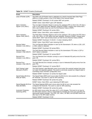
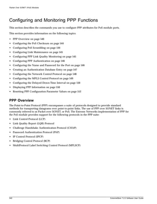
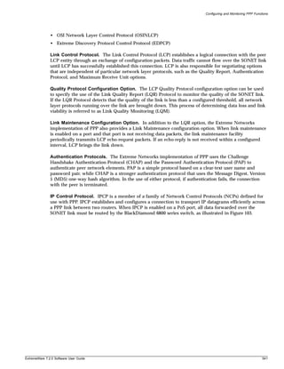
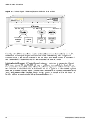
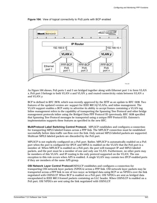
![Packet Over SONET (PoS) Modules
OSINLCP is not explicitly configured on a PoS port, it is automatically enabled on a PoS port when the
port is configured for IPCP and IS-IS is enabled on the VLAN that the PoS port is a member of. When
OSINLCP is enabled on a PoS port, the port will transport IP as well as OSI network layer packets. As
with IPCP, the port must be a member of one and only one VLAN. Furthermore, no other ports may be
members of this VLAN, and IP routing is the only protocol supported on the VLAN. The one exception
to this rule occurs when APS is enabled. A single VLAN may contain two IPCP-enabled ports if they
are members of the same APS group.
Extreme Discovery Protocol Control Protocol. EDPCP supports the exchange of EDP control
packets across PoS links. EDP is used to gather information about neighboring Extreme switches, and to
exchange topology information. EDPCP uses PPP protocol ID 0x820D; EDP packets use PPP protocol ID
0x020D. These PPP protocol IDs were assigned by the Internet Assigned Numbers Authority (IANA).
When the PPP peer is from a vendor other than Extreme, EDPCP is disabled on the link.
Creating a PPP User Account
The following command is an enhanced application of the existing ExtremeWare create account
command. The pppuser keyword is used to specify the name of a local database entry that is used to
authenticate PPP peers.
create account pppuser <username> {encrypted} {<password>}
The PPP use of this command is described in “Creating an Authentication Database Entry” on page 547.
Configuring the PoS Checksum
To configure the size of the HDLC Frame Check Sequence (FCS) to be used on the specified SONET
port, use the following command:
configure ppp pos checksum [32 | 16] ports <portlist>
Choose either the 32-bit FCS or the 16-bit FCS. A 32-bit FCS is the default. RFC 2615 recommends the
use of the 32-bit FCS.
NOTE
For OC-3 applications, RFC 2615 allows the use of a 16-bit FCS, but recommends using a 32-bit FCS.
You should limit your use of the 16-bit FCS to supporting interoperability with equipment that does not
support the 32-bit FCS.
The following command example sets the FCS to 16 for port 1 of the PoS module installed in slot 8 of
the BlackDiamond switch.
configure ppp pos checksum 16 ports 8:1
Configuring PoS Scrambling
To enable or disable payload data scrambling on the specified port, use the following command:
configure ppp pos scrambling [on | off] ports <portlist>
Choose either on or off. Scrambling is enabled by default.
544 ExtremeWare 7.2.0 Software User Guide](https://image.slidesharecdn.com/extremewareuserguide72-110124002726-phpapp01/85/Extreme-wareuserguide72-544-320.jpg)
![Configuring and Monitoring PPP Functions
RFC 2615 recommends that the SONET payload be scrambled. The option of disabling scrambling is
provided for backward compatibility with an earlier PoS standard. Scrambling was introduced in RFC
2615 to alleviate potential security problems where malicious users might intentionally generate packets
with bit patterns that create SONET synchronization problems.
The following command example turns off the scrambling function for port 1 of the PoS module
installed in slot 8 of the BlackDiamond switch.
configure ppp pos scrambling off ports 8:1
Configuring Link Maintenance
The Extreme Networks implementation of PPP provides a link maintenance configuration option. When
link maintenance is enabled on a port and that port is not receiving data packets, the link maintenance
facility periodically transmits Link Control protocol (LCP) echo-request packets. If an echo-reply is not
received within a configured interval, LCP brings the link down.
To enable the link maintenance protocol on a specified PPP port, use the following command:
configure ppp echo [<seconds> <consecutive_misses> | off] ports <portlist>
The seconds parameter is an integer in the range from 1 to 300 that specifies the period between
transmissions of echo-request packets.
The consecutive_misses parameter is an integer in the range from 1 to 100 that determines how long
PPP waits for a reply. If an echo-reply is not received within an interval of duration (consecutive_misses *
seconds) seconds, the link is brought down.
When APS is enabled on a SONET port, link maintenance should also be enabled on that port.
The link maintenance protocol is off by default. If you enable link maintenance, the recommended
seconds value is 3, and the recommended consecutive_misses value is 10.
The following example enables link maintenance on port 1 of a PoS module in slot 8 and sets seconds
to 3 and consecutive misses to 10.
configure ppp echo 3 10 ports 8:1
Configuring PPP Link Quality Monitoring
The Link Control Protocol (LCP) establishes a logical connection with the peer LCP entity through an
exchange of configuration packets. Data traffic cannot flow over the SONET link until LCP has
successfully established this connection. LCP also allows the negotiation of a quality monitoring
protocol to monitor the viability of the PPP link on a continuous basis. This process of determining data
loss and link viability is referred to as Link Quality Monitoring (LQM).
The LQM protocol uses the Link Quality Report (LQR) packet as a mechanism in the test of the PPP
link. The LQM protocol periodically transmits LQR packets containing counts of packets and octets that
have been transmitted and successfully received. This information enables the LQM protocol to
determine the percentage of data that is being dropped due to poor link quality. If the drop percentage
is greater than a configured threshold, all network-layer protocols are brought down. Bringing a
poor-quality link down may be desirable when an alternate network path exists, or when billing is
based on the amount of data transmitted. By default, LQM is off.
To enable the LQM protocol on a specified PPP port, use the following command:
ExtremeWare 7.2.0 Software User Guide 545](https://image.slidesharecdn.com/extremewareuserguide72-110124002726-phpapp01/85/Extreme-wareuserguide72-545-320.jpg)
![Packet Over SONET (PoS) Modules
configure ppp quality [off | <required_percent> {<seconds>}] ports <portlist>
The required_percent parameter is an integer in the range from 1 to 99 that is used to determine the
drop percentage threshold, where:
drop percentage threshold = (100–<required_percent>).
The optional seconds parameter is an integer in the range from 1 to 300. This parameter value
determines how often quality reports should be received from the peer LQR entity. If you do not specify
a value for the seconds parameter, the command uses the default value of 30 seconds.
It can take up to seven reporting intervals for LCP to bring a link down. If the link quality improves
subsequent to being brought down, LCP automatically brings the link back up. This type of service
restoration takes a minimum of seven reporting intervals.
The following example enables the LQM protocol on port 1 of a PoS module in slot 3 and sets
required_percent to 95. Because no value is specified for the optional seconds parameter, the
command uses the default of 30 seconds.
configure ppp quality 95 ports 3:1
Configuring PPP Authentication
The Extreme Networks implementation of PPP uses the Challenge Handshake Authentication Protocol
(CHAP) and the Password Authentication Protocol (PAP) to authenticate peer network elements. PAP is
a simple protocol based on a clear-text user name and password pair, while CHAP is a stronger
authentication protocol that uses the Message Digest, Version 5 (MD5) one-way hash algorithm. In the
use of either protocol, if authentication fails, the connection with the peer is terminated.
To configure authentication on a specified PPP port, use the following command:
configure ppp authentication [off | chap | pap | chap-pap] ports <portlist>
The default is authentication off, meaning the peer is not authenticated.
When you configure authentication using the chap keyword, the peer is authenticated using CHAP.
When you configure authentication using the pap keyword, the peer is authenticated using PAP.
When you configure authentication using the chap-pap keyword, a request is made to authenticate the
peer using CHAP, but PAP may be used if the peer does not support CHAP.
The following command example turns on CHAP authentication for port 1 of the PoS module installed
in slot 8 of the BlackDiamond switch.
configure ppp authentication chap ports 8:1
Configuring the Name and Password for the Port
In the event a PPP peer requests authentication, the Extreme Networks implementation of PPP responds
to the peer’s CHAP or PAP authentication requests regardless of whether the port is configured to
authenticate the peer.
To configure the name and password for a specified PPP port, use the following command:
546 ExtremeWare 7.2.0 Software User Guide](https://image.slidesharecdn.com/extremewareuserguide72-110124002726-phpapp01/85/Extreme-wareuserguide72-546-320.jpg)
![Packet Over SONET (PoS) Modules
Configuring the Network Control Protocol
The Network Control Protocol is configured on a per-port basis, meaning that different ports on the
same module can be running either the Bridging Control Protocol (BCP) or the IP Control Protocol
(IPCP)—both protocols cannot be configured at the same time on any port.
Generally, when IPCP is configured on a port, that port must be a member of a single VLAN. Further,
no other ports on this switch can be members of this VLAN, and IP routing is the only protocol
supported on this VLAN. The one exception to this rule is when Automatic Protection Switching (APS)
is enabled. In which case, a single VLAN may contain two ports configured for IPCP if they are both
members of the same APS group.
NOTE
For more information about setting up VLANs, see Chapter 6.
BCP establishes and configures a connection for transporting Ethernet MAC frames across a PPP link.
Because BCP carries Ethernet MAC frames, any protocol can be transported across a BCP connection. In
a simplified sense, BCP allows the PoS link to appear as an Ethernet LAN segment to the rest of the
switch, so BCP makes it possible for LAN services to be extended transparently across SONET
wide-area networks. Therefore, the port can be a member of multiple VLANs, and frames can be either
bridged or routed onto the link.
Generally, most of the switch capabilities provided for Ethernet ports are also available for PoS ports
configured for BCP. One exception is that there are restrictions on which OC-3 PoS module ports can be
bridged together (be configured as members of the same VLAN). Ports 1 and 2 on the same OC-3 PoS
module cannot be bridged together, and ports 3 and 4 on the same OC-3 PoS module cannot be bridged
together—unless they are members of the same APS group. There are no such restrictions on OC-12 PoS
module ports.
To configure the Network Control Protocol for a specified PPP port, use the following command:
configure ppp [bcp [on | off] | ipcp [on {peer-ipaddress <ip address>} | off]] ports
<portlist>
By default, BCP is enabled on all PoS ports. BCP cannot be configured on a port unless IPCP is off;
IPCP cannot be configured on a port unless BCP is off.
When used with IPCP, the optional peer-ipaddress keyword and parameter value provides a way to
configure the IP address of the peer router. This capability is useful with peer routers that do not
advertise their IP address through the IPCP IP-Address configuration option. If the peer router does
advertise an IP address through IPCP, the configured value for peer-ipaddress is ignored.
The following command example turns IPCP off and BCP on for port 1 of the PoS module installed in
slot 8 of the BlackDiamond switch.
configure ppp ipcp off port 8:1
configure ppp bcp on port 8:1
548 ExtremeWare 7.2.0 Software User Guide](https://image.slidesharecdn.com/extremewareuserguide72-110124002726-phpapp01/85/Extreme-wareuserguide72-548-320.jpg)
![Configuring and Monitoring PPP Functions
Configuring the MPLS Control Protocol
MPLSCP establishes and configures a connection for transporting MPLS labeled frames across a PPP
link. The MPLSCP connection must be established successfully before MPLS labeled data traffic can
flow over the link. Only unicast MPLS labeled packets are supported. Multicast MPLS labeled packets
are discarded by the PoS port.
MPLSCP is not explicitly configured on a PoS port. However, MPLSCP is automatically enabled on a
PoS port when the port is configured for IPCP and MPLS is enabled on the VLAN that the PoS port is a
member of. When MPLSCP is enabled on a PoS port, the port will transport IP and MPLS labeled
packets, and the port must be a member of one and only one VLAN. Furthermore, no other ports may
be members of this VLAN, and IP routing is the only protocol supported on the VLAN. The one
exception to this rule occurs when APS is enabled. A single VLAN may contain two IPCP-enabled ports
if they are members of the same APS group.
NOTE
You must have a PoS module and an MPLS module installed in your BlackDiamond switch to use MPLS
on a PoS port.
To configure MPLSCP on a PoS port, complete the following steps:
1 Create a VLAN for the PoS port using the create vlan <vlan name> command.
2 Add the PoS port to the VLAN using the configure vlan <vlan name> add ports <portlist>
{tagged | untagged} {nobroadcast} {soft-rate-limit} command.
3 Define an IP router port on the VLAN by assigning an IP address to the VLAN using the configure
vlan <vlan name> ipaddress <ipaddress> {<netmask> | <mask length>} command.
4 Disable BCP on the PoS port using the configure ppp bcp off ports <portlist> command
and enable IPCP on the PoS port using the configure ppp ipcp on ports <portlist>
command.
5 Configure MPLS on the VLAN using the configure mpls add vlan [<vlan name> | all] {ldp
| rsvp-te} command.
The following command example creates a VLAN named vlan1 and configures MPLSCP on PoS port 8:1
on VLAN vlan1:
create vlan vlan1
configure vlan vlan1 add ports 8:1
configure vlan vlan1 ipaddress 192.168.100.1
configure ppp bcp off ports 8:1
configure ppp ipcp on ports 8:1
configure mpls add vlan vlan1
For more information about MPLS and configuring MPLS, see Chapter 26.
Configuring the OSI Network Layer Control Protocol
OSINLCP implementation is based on RFC 1337. OSINLCP establishes and configures a connection for
transporting OSI network layer packets (NPDUs) across a PPP link. OSI network layer packets may be
transported across a PPP link in one of two ways: as bridged data using BCP or as NPDUs over the link
negotiated with OSINLCP. When BCP is enabled on a PoS port, OSI NPDUs are sent as bridged data
ExtremeWare 7.2.0 Software User Guide 549](https://image.slidesharecdn.com/extremewareuserguide72-110124002726-phpapp01/85/Extreme-wareuserguide72-549-320.jpg)
![Packet Over SONET (PoS) Modules
encapsulated in IEEE 802.3 framed packets containing an LLC header. When OSINLCP is enabled on a
PoS port, OSI NPDUs are sent using the link negotiated with OSINLCP.
OSINLCP is not explicitly configured on a PoS port, it is automatically enabled on a PoS port when the
port is configured for IPCP and IS-IS is enabled on the VLAN that the PoS port is a member of. When
OSINLCP is enabled on a PoS port, the port will transport IP as well as OSI network layer packets. As
with IPCP, the port must be a member of one and only one VLAN. Furthermore, no other ports may be
members of this VLAN, and IP routing is the only protocol supported on the VLAN. The one exception
to this rule occurs when APS is enabled. A single VLAN may contain two IPCP-enabled ports if they
are members of the same APS group.
To configure OSINLCP on a PoS port, complete the following steps:
1 Create a VLAN for the PoS port using the create vlan <vlan name> command.
2 Add the PoS port to the VLAN using the configure vlan <vlan name> add ports <portlist>
{tagged | untagged} {nobroadcast} {soft-rate-limit} command.
3 Define an IP router port on the VLAN by assigning an IP address using the configure vlan <vlan
name> ipaddress <ipaddress> {<netmask> | <mask length>} command.
4 Disable BCP on the SONET port using the configure ppp bcp off ports <portlist> command,
and then enable IPCP with configure ppp ipcp on ports <portlist>.
5 Enable IS-IS on the VLAN using the configure isis add vlan [<vlan name> | all]
[[level-1 | level-1-2] area <isis area identifier> | level-2-only] command.
Configuring the Delayed-Down-Time Interval
The delayed-down-time interval is the amount of time that PPP waits before declaring a port down
after a physical link failure has been detected. A non-zero value is useful when recovery from the link
failure is fast, for example, when APS is enabled on a SONET port. In this case, APS may recover from
the link failure before PPP responds, thereby minimizing network down time. Generally, you should set
a non-zero value for the delayed-down-time interval any time APS is configured at either end of the
link.
To configure the delayed-down-time interval for a specified PPP port, use the following command:
configure ppp delayed-down-time <seconds> ports <portlist>
The value of the seconds parameter is an integer number in the range from 0 to 20 seconds. The default
is 1 second.
NOTE
A delayed-down-time interval of one second is usually sufficient to accommodate APS line switches.
The following command example sets the delayed-down-time interval to 2 seconds for port 1 of the PoS
module installed in slot 8 of the BlackDiamond switch.
configure ppp delayed-down-time 2 ports 8:1
Displaying PPP Information
To display status information for PPP ports, use the following command:
550 ExtremeWare 7.2.0 Software User Guide](https://image.slidesharecdn.com/extremewareuserguide72-110124002726-phpapp01/85/Extreme-wareuserguide72-550-320.jpg)
![Packet Over SONET (PoS) Modules
Resetting PPP Configuration Parameter Values
To reset the PPP configuration parameters for the specified port to their default values, use the
following command:
unconfigure ppp ports <portlist>
Configuring VLAN-Related Attributes
The ExtremeWare software and the Extreme Networks switch architecture provide a range of Virtual
Local Area Network (VLAN) features, which are described in detail in Chapter 6. This section describes
how these features are supported on the PoS module.
NOTE
This section assumes some familiarity with the Extreme Networks implementation of VLAN features as
described in Chapter 6.
PoS module ports do not support protocol-based VLANs or MAC address VLANs. Thus, there are
restrictions on the use of the following commands:
• configure vlan <vlan name> add ports <portlist> {tagged | untagged} {nobroadcast}
{soft-rate-limit}
• configure vlan <vlan name> delete port <portlist>
• configure vlan <vlan name> protocol [<protocol_name> | any]
• enable mac-vlan mac-group [any | <group_number>] port <portlist>
The restrictions are as follows:
• A PoS port cannot be added to a VLAN if the VLAN is a protocol-based VLAN.
• A VLAN cannot be configured to be a protocol-based VLAN if the VLAN contains a PoS port.
• A MAC address VLAN cannot be enabled on a PoS port.
The configure vlan <vlan name> protocol [<protocol_name> | any] command is supported,
because it can be used to configure the default VLAN for PoS ports.
In the configure vlan <vlan name> add ports <portlist> {tagged | untagged}
{nobroadcast} {soft-rate-limit} command, PoS ports support the optional tagged and untagged
keywords when BCP is enabled, and ignore them when IPCP is enabled.
IPCP and BCP are mutually exclusive configuration options for a given PoS port: they cannot both be
enabled simultaneously on the same PoS port. Generally, when IPCP is enabled on a port, the port must
be a member of one and only one VLAN. Furthermore, no other ports may be members of this VLAN,
and IP routing is the only protocol supported on the VLAN. The one exception to this rule occurs when
APS is enabled. A single VLAN may contain two IPCP-enabled ports if they are members of the same
APS group.
552 ExtremeWare 7.2.0 Software User Guide](https://image.slidesharecdn.com/extremewareuserguide72-110124002726-phpapp01/85/Extreme-wareuserguide72-552-320.jpg)
![Configuring VLAN-Related Attributes
Configuring Tagged VLAN 802.1p and 802.1Q Functions
NOTE
The dot1q tag mapping and tag nesting commands are supported only by PoS ports and apply only
when BCP is enabled on the PoS port.
The following ExtremeWare commands are supported for the PoS module:
• configure dot1q ethertype <ethertype>
• configure dot1p type <dot1p_priority> qosprofile <qosprofile>
NOTE
If a PoS port receives a frame with a priority value “n” that is not mapped to a profile in the range from
qp1 through qp8, the frame is assigned to QoS profile qpn+1.
The following commands provide PoS module support for managing 802.1Q tags:
• configure dot1q tagmapping <input_vlanid/output_vlanid> ports <portlist> {egress
{priority <priority>} | ingress {priority <priority>}}
• configure dot1q tagnesting {<vlanid> | <vlanid_range>} [off | pop | push
<new_vlanid> {priority <priority>}] ports <portlist> {egress | ingress}
Configuring VLAN Tag Mapping Tables
The configure dot1q tagmapping command provides support for VLAN ID (VID) mapping tables.
Each PoS port supports two VID tables: one table is used in the ingress direction; the other is used in
the egress direction. These tables make it possible to map an input VID to an output VID, which can be
useful in reconciling policy differences at the boundary between the customer and the service provider.
The tables also allow the option of preserving the 802.1p priority or overwriting the priority with a
configured value.
To configure the VLAN tag mapping tables for a PoS port, use the following command:
configure dot1q tagmapping <input_vlanid/output_vlanid> ports <portlist> {egress
{priority <priority>} | ingress {priority <priority>}}
The input_vlanid and output_vlanid parameters are both integers in the range from 1 to 4095 and
must be separated by a slash character.
The priority parameter is an integer in the range from 0 to 7.
Use the egress keyword to apply the mapping of the input VLAN ID to the output VLAN ID to frames
received from the switch backplane prior to transmitting them onto the PPP link. Use the ingress
keyword to apply the mapping to input frames received from the PPP link. The mappings are applied
after they are classified to a QoS profile. Frames containing the VLAN ID specified in input_vlanid are
changed so that the VLAN ID is set to the value specified in output_vlanid before the frame is
forwarded.
If you omit both the egress and the ingress keywords, the command automatically applies the
specified mapping to the egress direction, and also applies a symmetrical mapping (with the
input_vlanid and output_vlanid values reversed) to the ingress direction.
ExtremeWare 7.2.0 Software User Guide 553](https://image.slidesharecdn.com/extremewareuserguide72-110124002726-phpapp01/85/Extreme-wareuserguide72-553-320.jpg)
![Packet Over SONET (PoS) Modules
These tables also give you the option of preserving the 802.1p priority or overwriting the priority with a
user-configured value. Using the priority keyword in the command indicates that the 802.1p priority
field is to be set to the value specified in priority. To preserve the 802.1p priority, do not enter the
priority keyword and value when using this command.
The default behavior is that the tables are initialized such that VLAN IDs are not altered by the
mapping operations, and frame priority is preserved. For example, an input VLAN ID of n is always
mapped to an output VLAN ID of n, and the 802.1p priority field is not changed.
Configuring VLAN Tag Nesting Attributes
The configure dot1q tagnesting command provides support for 802.1Q tags by allowing a tag push
or pop attribute to be associated with a VLAN ID. The push attribute indicates that a new tag is to be
added to the frame, while the pop attribute indicates that the top-level tag is to be removed from the
frame. The command also gives you the option to preserve the 802.1p priority of the frame or set it to a
configured value when a new tag is added (pushed) to the frame. VLAN ID (VID) mapping occurs
before a new tag is pushed, and after a nested tag is popped.
To configure the VLAN tag nesting attributes for a PoS port, use the following command:
configure dot1q tagnesting {<vlanid> | <vlanid_range>} [off | pop | push <new_vlanid>
{priority <priority>}] ports <portlist> {egress | ingress}
The vlanid parameter is an integer in the range from 1 to 4095. The vlanid_range parameter is
specified in the form start_vlanid-end_vlanid, where the start and end values are both integers in the
range from 1 to 4095 and must be separated by a hyphen.
The push keyword indicates that a new tag is to be added to frames containing the VID specified in
vlanid or to one of the VIDs in the range specified in vlanid_range. The new tag added to frames
contains the value specified in new_vlanid.
The pop keyword indicates that the top-level tag is to be removed from frames when that tag contains
either the VID specified in vlanid or any one of the VIDs in the range specified in vlanid_range.
If you do not specify a VID or a range of VIDs, the command settings are applied to all VIDs.
Tag operations can be performed in either the egress direction (to the SONET link) or the ingress
direction (from the SONET link). If you do not specify a direction, the default behavior is that tag
operations are performed in the egress direction. If you do not use either the egress or ingress
keyword and tag pushing is configured, a corresponding tag pop operation is automatically configured
for the ingress direction. If you do not use either the egress or ingress keyword and tag nesting is
disabled using the off keyword, tag nesting is disabled in both directions.
The optional priority keyword provides a way to overwrite the 802.1p priority with a user-configured
value when a new tag is pushed. Using the priority keyword in the command indicates that the
802.1p priority field is to be set to the value specified in priority, which is an integer in the range from
0 to 7. To preserve the 802.1p priority, do not enter the priority keyword and value when using this
command.
Default behavior is that tag nesting is disabled (off) for all VLAN IDs.
Tag push operations apply to egress frames only when the port is configured to transmit tagged frames
for the associated VLAN. Tag nesting operations apply only to ingress frames that contain a VLAN tag.
Tag nesting operations are applied after classification to a QoS profile.
554 ExtremeWare 7.2.0 Software User Guide](https://image.slidesharecdn.com/extremewareuserguide72-110124002726-phpapp01/85/Extreme-wareuserguide72-554-320.jpg)
![Packet Over SONET (PoS) Modules
• Enhanced RED Support on page 560
Configuring a QoS Profile
The SONET modules support eight ingress queues and eight egress queues per port. The scheduling
parameters (minimum bandwidth, maximum bandwidth and priority level) for these queues are
controlled by QoS profiles qp1 through qp8, which are defined using the existing ExtremeWare
configure qosprofile command.
This command has been enhanced to allow you to configure more module-specific parameters on a
port-by-port basis, including the ability to customize the QoS profile parameters for individual ingress
or egress queues on a specific SONET port.
The syntax and description of the enhanced configure qosprofile command are described below.
To configure the scheduling parameters for a specified QoS profile, use the following command:
configure qosprofile <qosprofile> minbw <min_percent> maxbw <max_percent> priority
<level> {[minbuf <percent> maxbuf <number> [K | M] | maxbuff <number> [K | M] |
<portlist>]}
The optional egress and ingress keywords apply only to PoS ports. As stated earlier, the PoS modules
support eight egress queues and eight ingress queues per port, and the scheduling parameters for these
queues are controlled by QoS profiles qp1-qp8, which means queue #0 is controlled by qp1, queue #1 is
controlled by qp2, and so on.
The optional portlist parameter allows QoS profiles to be customized on a port-by-port basis for the
PoS modules. The egress and ingress keywords allow you to fine-tune the customization (down to a
particular egress or ingress queue on a given port). If you do not enter either the egress or ingress
keyword in the command, the configured parameters apply to the egress queue associated with the
specified QoS profile by default.
The minbw parameter specifies the minimum percentage of the bandwidth guaranteed to be available to
the specified queue for transmissions from the QoS profile. The value is an integer in the range from 0
through 100. The default value is 0. The sum of the minimum bandwidth parameters across all eight
QoS profiles cannot exceed 90%.
The maxbw parameter specifies the maximum percentage of the bandwidth that the specified queue can
use for transmissions from the QoS profile. The value is an integer in the range from 1 through 100. The
default value is 100.
The optional priority keyword and level parameter specify the service priority for the specified
queue. The service priority determines which traffic is scheduled when bandwidth is still available after
the minimum requirements of all profiles have been satisfied. Settings for level include: low, lowHi,
normal, normalHi, medium, mediumHi, high, or highHi. The default setting is low.
NOTE
The minbuf and maxbuf keywords do not apply to PoS ports.
Classification and Replacement Policies
This section deals primarily with classification operations performed by IPCP or BCP configured PoS
ports.
556 ExtremeWare 7.2.0 Software User Guide](https://image.slidesharecdn.com/extremewareuserguide72-110124002726-phpapp01/85/Extreme-wareuserguide72-556-320.jpg)
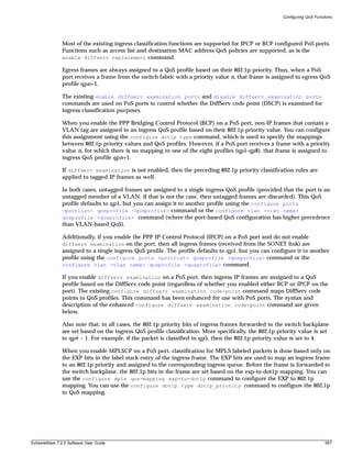
![Packet Over SONET (PoS) Modules
When you configure MPLSCP on a PoS port, other types of ingress commands such as configure
diffserv examination code-point, configure ports <portlist> qosprofile <qosprofile>,
and configure vlan <vlan name> qosprofile <qosprofile> are supported only for IPCP data
frames and not MPLS labeled frames. Similarly, egress replacement commands such as enable dot1p
replacement and enable diffserv replacement are supported only for IPCP data frame and not
MPLS labeled frames.
Configuring DiffServ
All of the existing ExtremeWare DiffServ commands are supported by PoS ports with IP frames that are
encapsulated in BCP or IPCP, not MPLSCP (including the enhancements to the configure diffserv
examination code-point command, described earlier in this chapter). PoS ports also support a
DiffServ code point (DSCP) mapping function that you configure using the configure diffserv
dscp-mapping command, which is described below. The DSCP is a 6-bit value in the IP-TOS byte of the
IP packet header. For more information on DSCPs, see “Configuring DiffServ” in Chapter 8.
DiffServ Classification
When a packet arrives at the switch on an ingress port, the switch examines the first six of eight TOS
bits, called the code point. The switch can assign the QoS profile used to subsequently transmit the
packet based on the code point. The QoS profile controls a hardware queue used when transmitting the
packet out of the switch, and determines the forwarding characteristics of a particular code point. The
examination of DiffServ information is disabled by default. To enable examination of DiffServ
information, use the command:
enable diffserv examination ports [<portlist> | all]
Changing DiffServ Code Point Assignments in the QoS Profile
Because the code point uses six bits, it has 64 possible values (26 = 64). By default, the values are
grouped and assigned to the default QoS profiles listed in Table 75.
Table 75: Default Code Point-to-QoS Profile Mapping
Code Point QoS Profile
0-7 Qp1
8-15 Qp2
16-23 Qp3
24-31 Qp4
32-39 Qp5
40-47 Qp6
48-55 Qp7
56-63 Qp8
To configure the mapping between a DiffServ code point and a specified QoS profile, use the following
command:
configure diffserv examination code-point <code_point>
qosprofile <qosprofile> ports <portlist>
{low-drop-probability | high-drop-probability}
558 ExtremeWare 7.2.0 Software User Guide](https://image.slidesharecdn.com/extremewareuserguide72-110124002726-phpapp01/85/Extreme-wareuserguide72-558-320.jpg)
![Packet Over SONET (PoS) Modules
If you omit the no-congestion and congestion keywords, the command applies the mapping to the
tables for both states.
If you omit the egress and ingress keywords, the command applies the mapping to the egress
direction, and automatically configures a symmetrical mapping (with the input_codepoint and
output_codepoint values reversed) in the ingress direction.
By default, all the tables are initialized such that DSCPs are not altered by the mapping operations. For
example, an input DSCP value of n is always mapped to an output DSCP value of n.
Resetting DiffServ Code Point Mapping Tables
To reset the DSCP mapping tables for a specified PoS port to their default values, use the following
command:
unconfigure diffserv dscp-mapping ports <portlist>
Replacing DiffServ Code Points
To replace DiffServ code points, you must use the following command to enable DiffServ replacement:
enable diffserv replacement ports [<portlist> | all]
You then change the 802.1p priority to DiffServ code point mapping to any code point value using the
following command:
configure diffserv replacement priority <value> code-point <code_point> ports
[<portlist> | all]
By doing so, the hardware queue used to transmit a packet determines the DiffServ value replaced in
the IP packet.
To verify the DiffServ configuration, use the command:
show ports {mgmt | <portlist>} info {detail}
Enhanced RED Support
Random Early Detection (RED) is a congestion avoidance mechanism. The basic idea behind RED is that
most data transports detect packet loss and will, therefore, restrain transmission—if only
temporarily—when they detect dropped packets. Consequently, if the switch needs to signal another
device to slow transmission due to congestion, RED provides a way of intelligently dropping packets.
This section describes the changes and additions to ExtremeWare to support RED in conjunction with
PoS modules that have IP frames encapsulated in BCP or IPCP, not MPLSCP. The Extreme
implementation of RED combines the functions of the RED algorithm with IP precedence to provide
support for preferential traffic handling for higher-priority packets. This implementation provides
weighted RED (WRED) functionality through two packet-drop probabilities (described below), so that a
device can selectively drop lower-priority traffic when an interface begins to show signs of congestion.
This capability is combined with DiffServ attributes to allow you to tailor performance characteristics
for different classes of service.
Configuring RED Drop Probability
To configure the RED drop probability for a specified PoS port, use the following command:
560 ExtremeWare 7.2.0 Software User Guide](https://image.slidesharecdn.com/extremewareuserguide72-110124002726-phpapp01/85/Extreme-wareuserguide72-560-320.jpg)
![Configuring QoS Functions
configure red [drop-probability | low-drop-probability | high-drop-probability]
<percent> {ports <portlist>}
The optional low-drop-probability, high-drop-probability, and ports keywords are supported
only for SONET ports.
If you omit the ports keyword, the command applies the setting to all ports.
The drop probability is specified as a percentage, where the percent parameter is an integer in the
range from 1 to 100.
Weighted RED (WRED) functionality is supported through two different drop probabilities: a
low-drop-probability and a high-drop-probability. The DiffServ code points of IP packets indicate
whether the packet should be dropped with low probability or high probability, and the appropriate
percentage is then applied if WRED is active.
NOTE
WRED is applied only to IP packets. The configure diffserv examination code-point command
gives you complete flexibility in assigning DSCPs to the two different drop-probability levels. This
configured mapping of DSCPs to drop-probability levels is used by WRED even if diffserv
examination is disabled on the port.
The drop-probability keyword indicates that the specified percentage should be used for both the
low and high drop-probabilities. This effectively disables WRED and reverts to standard RED operation.
For SONET ports, both the low and high drop-probabilities default to 10%.
The role of the configured drop probability in RED operation on SONET ports is illustrated in
Figure 105A. RED is active when the average queue length is between the minimum and maximum
thresholds. In this region, the probability that a given packet is dropped increases in a straight line up
to the configured drop probability at the maximum threshold. All packets are dropped when the
average queue length exceeds the maximum threshold.
The operation of WRED on SONET ports is depicted in Figure 105B. In this case, the drop probability
depends not only on the average queue length, but also upon whether the DSCP indicates that the
packet should be dropped with a low or high probability, which is to say, the DSCP of the packet
controls which curve is used.
ExtremeWare 7.2.0 Software User Guide 561](https://image.slidesharecdn.com/extremewareuserguide72-110124002726-phpapp01/85/Extreme-wareuserguide72-561-320.jpg)
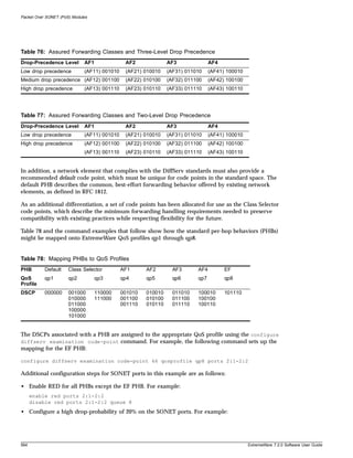
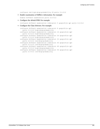
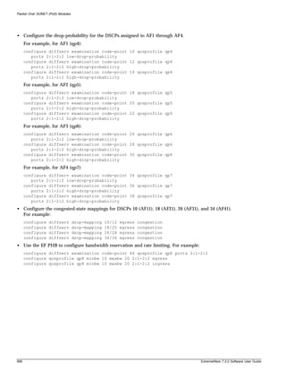
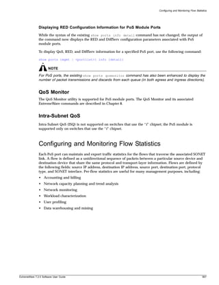
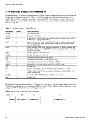
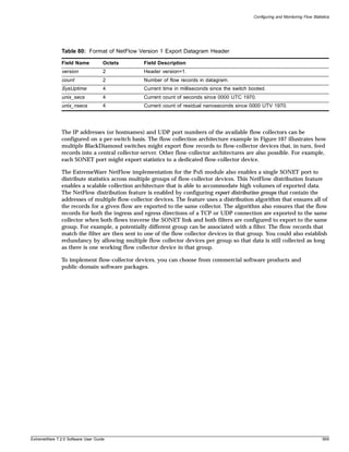
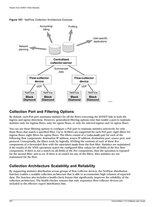
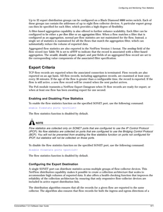
![Packet Over SONET (PoS) Modules
TCP or UDP connection are exported to the same collector (when both flows traverse the same SONET
link and both filters are configured to export to the same group).
NetFlow distribution is enabled by configuring export distribution groups that identify the addresses of
multiple flow-collector devices. You can configure up to 32 export distribution groups on a
BlackDiamond 6800 series switch, and each group can contain as many as eight flow-collector devices.
To configure the export groups and flow-collector devices to which NetFlow datagrams are exported,
use the following command:
configure flowstats export <group#> delete [<ipaddress> | <hostname>] <udp_port>
The optional group# parameter is an integer in the range from 1 through 32 that identifies the specific
group for which the destination is being configured. If you do not specify a value for the group#
parameter, the parameter value defaults to 1.
You can use the add and delete keywords to add or delete flow-collector destinations.
To export NetFlow datagrams to a group, you must configure at least one flow-collector destination. By
default, no flow-collector destinations are configured. To configure a flow-collector destination, use
either an IP address and UDP port number pair or a hostname and UDP port number pair to identify
the flow-collector device to which NetFlow export datagrams are to be transmitted. You can configure
up to eight flow-collector destinations for each group. When multiple flow-collectors are configured as
members of the same group, the exported NetFlow datagrams are distributed across the available
destinations.
Configuring the Source IP Address
To configure the IP address that is to be used as the source IP address for NetFlow datagrams to be
exported, use the following command:
configure flowstats source ipaddress <ipaddress>
No NetFlow datagrams are exported until the source IP address is configured. Depending on how it is
configured, a flow-collector device can use the source IP address of received NetFlow datagrams to
identify the switch that sent the information.
NOTE
The configured IP address should be associated with a VLAN that has loopback-mode enabled.
The following command example specifies that the IP address 192.168.100.1 is to be used as the source
IP address for exported NetFlow datagrams.
configure flowstats source ipaddress 192.168.100.1
Configuring Flow Record Timeout
Flow records are exported on an age basis: All flow records are examined at least once every 30
minutes. If the age of the flow record is greater than the configured timeout, the record is exported. If
the flow is still active, a new flow record will be created when the next packet arrives.
To configure the timeout value for flow records on the specified SONET port, use the following
command:
572 ExtremeWare 7.2.0 Software User Guide](https://image.slidesharecdn.com/extremewareuserguide72-110124002726-phpapp01/85/Extreme-wareuserguide72-572-320.jpg)
![Configuring and Monitoring Flow Statistics
configure flowstats timeout <minutes> ports [<portlist> | all]
The timeout value is the number of minutes to use in deciding when to export flow records. The
number is an integer in the range from 1 to 1440. The default timeout is 5 minutes.
The following command example specifies a 10-minute timeout for exported NetFlow datagrams on
port 1 of the PoS module installed in slot 8 of the BlackDiamond switch.
configure flowstats timeout 10 ports 8:1
Configuring a Flow Record Filter
You can configure a SONET port to maintain statistics selectively for only those flows that match a
specified filter. Each port on an PoS module supports 16 filters: eight filters for ingress flows; eight
filters for egress flows.
To configure a flow record filter for the specified SONET port, use the following command:
configure flowstats filter <filter#> {aggregation} {export <group#>} ports <portlist>
[ingress | egress] <filterspec>
where:
filter# The filter# parameter is an integer in the range from 1 to 8 that operates with either
the ingress or egress keyword to identify the filter that is being defined.
aggregation To reduce the volume of exported data, use this optional keyword to maintain a single
set of statistics for all the flows that match the specified filter.
export <group#> To specify a particular export distribution group on a per-filter basis, use the optional
export keyword with a group number value to identify the set of flow collector devices
to which records for flows matching the filter are to be exported. If you do not specify a
value for group#, the value defaults to 1.
ingress Use this keyword to specify that the filter being defined in the command is one of the
eight filters to be applied to ingress flows.
egress Use this keyword to specify that the filter being defined in the command is one of the
eight filters to be applied to egress flows.
ExtremeWare 7.2.0 Software User Guide 573](https://image.slidesharecdn.com/extremewareuserguide72-110124002726-phpapp01/85/Extreme-wareuserguide72-573-320.jpg)
![Packet Over SONET (PoS) Modules
filterspec Each filter is defined using a value/filtermask pair for each of the five components in
the following sequence:
{destination IP address, source IP address,
destination port number, source port number, protocol}
in the form:
[{dest-ip <ipaddress_value/ipaddress_filtermask>}
{source-ip <ipaddress_value/ipaddress_filtermask>}
{dest-port <port_value/port_filtermask>}
{source-port <port_value/port_filtermask>}
{protocol <protocol_value/protocol_filtermask>} |
match-all-flows | match-no-flows]
The ipaddress_filtermask, port_filtermask, and protocol_filtermask
parameters are configured using hexadecimal notation.
You can also use either the match-all-flows keyword or the match-no-flows
keyword in place of settings for the five components. The match-all-flows keyword
adjusts the value/filtermask settings for all the components to 0/0 such that the filter
matches any flow. The match-no-flows keyword adjusts the value/filtermask settings
for all the components such that the filter does not match any flow.
By default, filter #1 is configured to match-all-flows, and the remaining filters are
configured to match-no-flows.
Conceptually, the filters work by ANDing the contents of each of the five components of
a forwarded flow with the associated masks from the first defined filter (filter #1).
Statistics are maintained if the results of the AND operations match the configured filter
values for all fields of the sequence. If there is no match, then the operation is repeated
for filter #2, and so on. If there is no match for any of the filters, then statistics are not
maintained for the flow. Filters for any or all of the sequence components can be
configured with a single command.
The following command example configures a filter to collect statistics on ingress flows destined for
192.168.1.1 from the 192.169.0.0/16 subnet with a destination port of 80 using protocol 6.
configure flowstats filter 1 export 1 ports all ingress
dest-ip 192.168.1.1/FFFFFFFF source-ip 192.169.0.0/FFFF0000
dest-port 80/FFFF source-port 0/0 protocol 6/FF
Likewise, the following command example configures a filter to collect statistics on egress traffic from
the 192.168.0.0/16 subnet to 192.169.1.1 with a destination port of 80 using protocol 6.
configure flowstats filter 1 export 1 ports all egress
dest-ip 192.169.1.1/FFFFFFFF source-ip 192.168.0.0/FFFF0000
dest-port 80/FFFF source-port 0/0 protocol 6/FF
The following command example configures a filter to collect aggregate statistics for all egress traffic
flowing from the 192.170.0.0/16 subnet to the 192.171.255.255 subnet.
configure flowstats filter 2 aggregation export 1 ports all egress
dest-ip 192.171.0.0/FFFF0000 source-ip 192.170.0.0/FFFF0000
dest-port 0/0 source-port 0/0 protocol 0/0
Likewise, the following command example configures a filter to collect aggregate statistics for all ingress
traffic flowing from the 192.171.0.0/16 subnet to the 192.170.0.0/16 subnet.
configure flowstats filter 2 aggregation export 1 ports all ingress
dest-ip 192.170.0.0/FFFF0000 source-ip 192.171.0.0/FFFF0000
dest-port 0/0 source-port 0/0 protocol 0/0
574 ExtremeWare 7.2.0 Software User Guide](https://image.slidesharecdn.com/extremewareuserguide72-110124002726-phpapp01/85/Extreme-wareuserguide72-574-320.jpg)
![Packet Over SONET (PoS) Modules
removed from the export distribution list for that group. The flow collector device will be returned to
the export distribution list automatically when subsequent ping checks are consistently successful.
The following command example enables the ping-check function for export group 2.
enable flowstats ping-check 2
To disable the flow statistics ping-check function for a specified group of collector devices, use the
following command:
disable flowstats ping-check {<group#> | all}
If you do not specify a value for the group# parameter, the ping-check function is disabled for all
collector groups.
The following command example disables the ping-check function for export group 2.
disable flowstats ping-check 2
Unconfiguring Flow Statistics
To reset the flow statistics configuration parameters for a specified SONET port to their default values,
use the following command:
unconfigure flowstats ports [<portlist> | all]
NOTE
This command does not affect the enabled or disabled status of flow statistics collection, nor does it
affect the configured export destinations.
The following command example resets the flow statistics configuration parameters for port 1 of the
PoS module installed in slot 8 of the BlackDiamond switch to their default values.
unconfigure flowstats ports 8:1
Displaying Flow Statistics Status Information
To display status information for the flow statistics function, use the following command:
show flowstats {<portlist> | export {<group#>}}
where:
portlist Use this optional parameter to specify the SONET port for which status information is
to be displayed.
export Use this optional keyword to display status information for export groups, which are
configured on a switch-wide basis.
group# Use this optional parameter with the export keyword to display status information for
a specific export group. If you do not specify a value for the group# parameter, the
export keyword by itself displays status information for all export groups.
detail Use this optional keyword to display detailed export group status information.
If you enter the show flowstats command with none of the optional keywords or parameters, the
command displays a summary of status information for all ports.
576 ExtremeWare 7.2.0 Software User Guide](https://image.slidesharecdn.com/extremewareuserguide72-110124002726-phpapp01/85/Extreme-wareuserguide72-576-320.jpg)
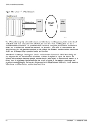
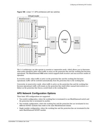
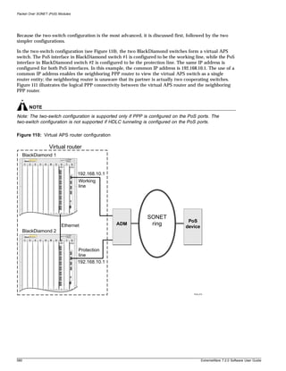
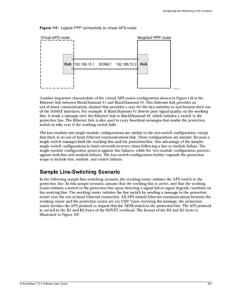
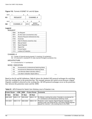
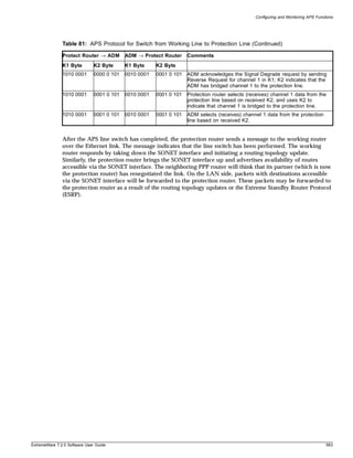
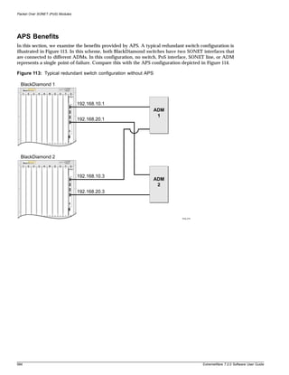
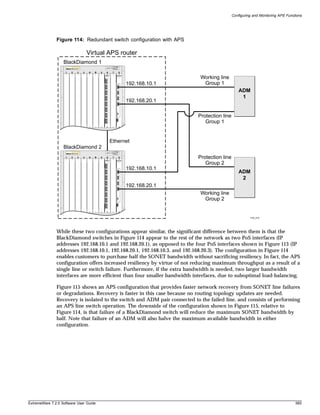
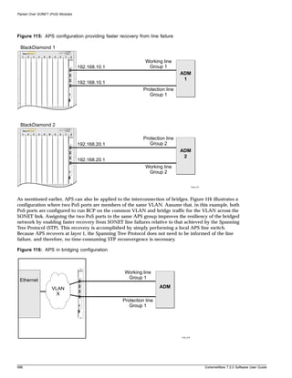
![Configuring and Monitoring APS Functions
Enabling and Disabling APS
To enable the APS function for the entire switch, use the following command:
enable aps
To disable the APS function for the entire switch, use the following command:
disable aps
Creating and Deleting an APS Group
An APS group includes one working line and one protection line. The working line and protection line
can reside on the same BlackDiamond switch or on two different BlackDiamond switches. The group is
identified by a unique number.
To create an APS group, use the following command:
create aps <group#>
The group# parameter is an integer in the range from 1 through 65535 that identifies the APS group to
be created. The APS group numbers must be unique across all BlackDiamond switches that are
cooperating to provide the APS function. The group numbers must also be used in a consistent manner
across BlackDiamond switches. For example, if the working line is assigned to group #1 on
BlackDiamond #1, and the associated protection line resides on BlackDiamond #2, the protection line
must also be assigned to group #1 on BlackDiamond #2. The group# is used to identify the partner line,
which can be either the working line or the protection line, in Ethernet messages exchanged by
BlackDiamond switches that are cooperating to provide the APS function.
The following command example creates APS group 1001 on the BlackDiamond switch:
create aps 1001
To delete an APS group, use the following command:
delete aps <group#>
The group# parameter is an integer in the range from 1 to 65535 that identifies the APS group to be
deleted.
The following command example deletes APS group 1001:
delete aps 1001
Adding a Port to an APS Group
To add a SONET port to an APS group, use the following command:
configure aps <group#> add <port> [working | protection <ip address>]
The group# parameter is an integer in the range from 1 to 65535 that identifies the APS group to which
the specified port is to be added.
The port parameter identifies the SONET port that is to be added to the APS group.
You must also specify whether the port is the APS working or protection line. You can add only one
working line and one protection line to an APS group. If you designate the port the protection line, then
you must also specify the IP address (ipaddress parameter) of the BlackDiamond switch where the
ExtremeWare 7.2.0 Software User Guide 587](https://image.slidesharecdn.com/extremewareuserguide72-110124002726-phpapp01/85/Extreme-wareuserguide72-587-320.jpg)
![Packet Over SONET (PoS) Modules
working line resides. This IP address is used to send APS control messages to the BlackDiamond switch
containing the working line.
NOTE
The configured IP address should be associated with an Ethernet VLAN that has loopback mode
enabled to minimize the impact of network outages on APS functionality. Also, when using APS to
protect links on different BlackDiamond 6800 series switches, the network connecting the working and
protection switches must always have sufficient bandwidth to support APS control transfers.
In routing configurations, the working line and the protection line should represent the same IP address
from the perspective of the neighboring PPP switch. When the working line and protection line reside
in the same BlackDiamond switch, both ports should be members of the same VLAN. The case where
both the working line and the protection line for an APS group reside in the same BlackDiamond switch
is the only situation where IPCP can be enabled on multiple SONET ports that are members of the same
VLAN. In general, if IPCP is enabled on a PoS module port, that port can be a member of only one
VLAN and no other ports on that switch can be members of that VLAN.
The following command example adds port 1 of the module installed in slot 8 of the BlackDiamond
switch to APS group 1001 as the working line.
configure aps 1001 add 8:1 working
Deleting a Port from an APS Group
To delete a SONET port from an APS group, use the following command:
configure aps <group#> delete <port>
The group# parameter is an integer in the range from 1 to 65535 that identifies the APS group from
which the specified port is to be deleted.
The port parameter identifies the SONET port that is to be deleted from the APS group.
NOTE
Deleting the working line from an APS group initiates a switch to the protection line, but deleting the
active protection line from an APS group does not initiate a switch to the working line.
The following command example deletes port 1 of the module installed in slot 8 of the BlackDiamond
switch from APS group 1001.
configure aps 1001 delete 8:1
Configuring APS Authentication
The authentication string is used to validate APS control frames received over an Ethernet link. If
authentication fails, the associated APS control frame is discarded.
To configure authentication of APS control messages, use the following command:
configure aps <group#> authenticate [off | on <string>]
588 ExtremeWare 7.2.0 Software User Guide](https://image.slidesharecdn.com/extremewareuserguide72-110124002726-phpapp01/85/Extreme-wareuserguide72-588-320.jpg)
![Configuring and Monitoring APS Functions
The group# parameter is an integer in the range from 1 to 65535 that identifies the APS group to which
the authentication command applies.
You must also specify whether authentication is to be turned off or turned on. The default setting is off.
If you are enabling authentication, you must also specify a text authentication string of no more than
eight alphanumeric characters as part of the command. If the working line and the protection line for an
APS group reside in different BlackDiamond switches, the same authentication string must be
configured at both BlackDiamond switches; otherwise, authentication will not work.
The following command example enables APS authentication for group 1001, with “seer5dog” as the
authentication string.
configure aps 1001 authenticate on seer5dog
Configuring Nonrevertive or Revertive Mode
You can configure the APS action that should be taken when traffic is active on the protection line and
the working line becomes operational.
The default switching mode is nonrevertive switching, which means traffic remains on the protection
line until either manual intervention or a failure on the protection line forces a switch back to the
working line.
If you configure revertive switching mode on an APS group, traffic is switched automatically from the
protection line to the working line after the user-defined Wait-To-Restore (WTR) period. The WTR
period minimizes frequent switching due to intermittent errors on the working line by restoring service
only when no errors are detected on the working line during the WTR period.
NOTE
A longer WTR period provides more protection against frequent switching by waiting to assure that the
working line is fully operational, but prolongs the time it takes to restore traffic to the working line after it
is fully operational.
To configure APS operation in either nonrevertive or revertive switching mode, use the following
command:
configure aps <group#> [nonrevert | revert <minutes>]
The group# parameter is an integer in the range from 1 to 65535 that identifies the APS group to which
the configuration command applies.
The minutes parameter is an integer in the range from 0 to 12. If you select revertive switching mode,
you must enter a value for minutes.
NOTE
This command applies only to SONET ports performing the protection line function.
ExtremeWare 7.2.0 Software User Guide 589](https://image.slidesharecdn.com/extremewareuserguide72-110124002726-phpapp01/85/Extreme-wareuserguide72-589-320.jpg)
![Packet Over SONET (PoS) Modules
The following command example configures APS group 1001 to operate in revertive switching mode,
with a WTR of 5 minutes.
configure aps 1001 revert 5
Configuring APS Timers
To set the values of the timers used in the APS hello protocol that is exchanged between the working
and protection switches for an APS group, use the following command:
configure aps <group#> timers <seconds> <consecutive_misses>
The group# parameter is an integer in the range from 1 to 65535 that identifies the APS group to which
this configuration command applies.
The seconds parameter is an integer in the range from 1 to 300 that specifies the amount of time the
protection switch waits between transmissions of hello packets to the working switch. The default value
is 1.
The consecutive_misses parameter is an integer in the range from 1 to 100 that controls the time
interval the protection switch waits before assuming that the working switch has failed. If the working
switch does not respond within consecutive_misses hello intervals, or ( consecutive_misses *
seconds) seconds, the protection switch assumes that the working switch has failed and initiates a line
switch. The default value is 5.
NOTE
In some cases, even if the working switch and working line are both operational, congestion might
temporarily slow the response time of the working switch to the point that the protection switch assumes
the working switch has failed, causing premature or unnecessary line switches. While setting larger
values for seconds and consecutive_misses will protect against premature or unnecessary line
switches, they can also delay a line switch when an actual switch failure occurs.
NOTE
This command applies only to SONET ports performing the protection line function.
The following command example configures the timers for APS group 1001 to 1 second and 3
consecutive misses.
configure aps 1001 timers 1 3
Configuring APS Lockout
You can specify that an APS group operates in lockout mode, which means switches from the working
line to the protection line are prohibited until you turn off lockout mode for that APS group. You
should use this command when you want to prevent a switchover to the protection line, such as when
the protection line is being reprovisioned, repaired, or debugged.
To control whether a switch to the protection line is locked out, use the following command:
configure aps <group#> lockout [off | on]
590 ExtremeWare 7.2.0 Software User Guide](https://image.slidesharecdn.com/extremewareuserguide72-110124002726-phpapp01/85/Extreme-wareuserguide72-590-320.jpg)
![Configuring and Monitoring APS Functions
The group# parameter is an integer in the range from 1 to 65535 that identifies the APS group to which
the lockout command applies.
By default, lockout mode is off.
NOTE
This command applies only to SONET ports performing the protection line function. Also, the settings
from this command are not preserved when the switch reboots.
The following command example turns on lockout mode for APS group 1001.
configure aps 1001 lockout on
Configuring Forced Switch Mode
You can request that an APS group be forced to use the working line as the active line, or be forced to
use the protection line as the active line. Use this command when you plan to perform service on the
other link and don’t want a switchover to occur.
To request that an APS group be forced to use a specified line as the active line, use the following
command:
configure aps <group#> force [off | working | protection]
The group# parameter is an integer in the range from 1 to 65535 that identifies the APS group to which
the force command applies.
The off keyword turns off forced switch mode. By default, force switch mode is off.
The working keyword forces the specified APS group to use the working line as the active line. The
protection keyword forces the specified APS group to use the protection line as the active line.
A forced switch is a high priority request. Only three events can override a forced switch request:
• A configure aps force off command
• A configure aps lockout on command (that was either in effect before the force command or
issued after the force command)
• A Signal Fail condition detected on the protection line
NOTE
This command applies only to SONET ports performing the protection line function. Also, the settings
from this command are not preserved when the switch reboots.
The following command example forces APS group 1001 to use the protection line as the active line:
configure aps 1001 force protection
ExtremeWare 7.2.0 Software User Guide 591](https://image.slidesharecdn.com/extremewareuserguide72-110124002726-phpapp01/85/Extreme-wareuserguide72-591-320.jpg)
![Packet Over SONET (PoS) Modules
Configuring Manual Switch Mode
You can manually determine whether an APS group uses its working line as the active line, or uses its
protection line as the active line. One potential use of this capability is to perform a manual switch back
to the working line after an error condition has cleared without waiting for the full Wait-To-Restore
period to elapse.
To manually determine whether an APS group uses its working line or its protection line as the active
line, use the following command:
configure aps <group#> manual [off | working | protection]
The group# parameter is an integer in the range from 1 to 65535 that identifies the APS group to which
the command applies.
The off keyword turns off manual switch mode. By default, manual switch mode is off.
The working keyword causes the specified APS group to use the working line as the active line. The
protection keyword causes the specified APS group to use the protection line as the active line.
A manual switch is a lower priority request than a forced switch. The following events can override a
manual switch:
• A configure aps manual off command
• A configure aps force working or a configure aps force protection command
• A configure aps lockout on command
• A detected Signal Fail or Signal Degrade line condition
NOTE
This command applies only to SONET ports performing the protection line function. Also, the settings
from this command are not preserved when the switch reboots.
The following command example configures APS group 1001 to use its working line as the active line:
configure aps 1001 manual working
Resetting APS Group Configuration Parameters
To reset the APS group configuration parameters to their default values, use the following command:
unconfigure aps <group#>
The group# parameter is an integer in the range from 1 to 65535 that identifies a particular APS group.
NOTE
This command does not affect the ports that have been added to the APS group, but does cancel any
outstanding lockout, force, or switch requests.
The following command example resets the configuration parameters of APS group 1001 to their default
values:
592 ExtremeWare 7.2.0 Software User Guide](https://image.slidesharecdn.com/extremewareuserguide72-110124002726-phpapp01/85/Extreme-wareuserguide72-592-320.jpg)
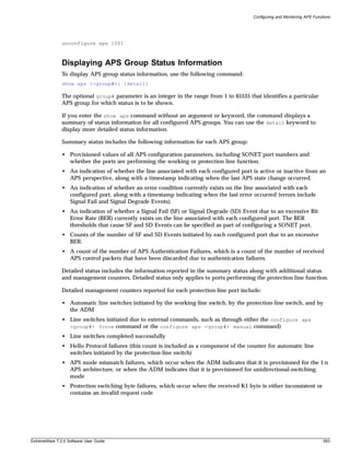
![Packet Over SONET (PoS) Modules
• Channel mismatch failures, which occur when the channel number in the transmitted K1 byte does
not match the channel number in the received K2 byte
• Far-end protection line failures, which occur when a Signal Fail request code is received on the
protection line
Additional detailed status information reported for each protection-line port includes:
• Current contents of received K1 and K2 bytes
• Contents of K1 and K2 bytes that are currently being transmitted
• Indication of whether an APS Mode Mismatch Failure is currently active
• Indication of whether a Protection Switching Byte Failure is currently active
• Indication of whether a Channel Mismatch Failure is currently active
• Indication of whether a Far-End Protection Line Failure is currently active
MIB Support for APS
Because no standard MIBs are defined for managing the APS function, Extreme Networks has defined
and implemented an enterprise MIB that provides read-only support (GET operations but not SET
operations) for APS configuration parameters and status information. Any of the parameters that can be
set with the configure aps commands can be accessed using the MIB, and any of the status
information displayed by the show aps command can also be read using the MIB. For more information
on the MIB, see Appendix B.
Configuring Port Tunneling
Port tunneling can be used to encapsulate and transport the raw High-Level Data Link Control (HDLC)
encapsulated byte stream from one PoS port to another PoS port across an MPLS network. This allows
service providers to tunnel different types of SONET HDLC streams across a non-SONET backbone like
Ethernet. The initial implementation of port tunneling requires an MPLS backbone network.
The following ExtremeWare port command has been added to support HDLC tunneling on a PoS
module:
configure ports <portlist> tunnel hdlc [off | mpls]
After you configure the PoS port, you can tunnel HDLC encapsulated frames from a PoS port across a
SONET or Ethernet based MPLS network. The ingress PoS port encapsulates the entire HDLC frame,
including the HDLC header and FCS, inside an Ethernet/MPLS header. HDLC control bytes are
de-stuffed on the ingress PoS port. The egress PoS port strips the Ethernet/MPLS header and forwards
the HDLC frame. HDLC control bytes are stuffed on the egress PoS ports. HDLC idle bytes, x7E, are not
tunneled, but runts and aborted frames are tunneled. Figure 117 displays port tunneling between PoS
port 1:4 on BlackDiamond switch 1 and PoS port 8:4 on BlackDiamond switch 2 with a PPP link
between Customer switch 1 and Customer switch 2. PPP is not terminated on either BlackDiamond
switch 1 or BlackDiamond switch 2.
594 ExtremeWare 7.2.0 Software User Guide](https://image.slidesharecdn.com/extremewareuserguide72-110124002726-phpapp01/85/Extreme-wareuserguide72-594-320.jpg)
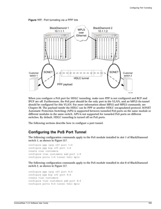
![Limitations and Unsupported Commands
• Configuring Access List Attributes on page 599
• Configuring Access List Attributes on page 599
• Configuring Access List Attributes on page 599
• Changing Image and Configuration Attributes on page 599
Configuring General Switch Attributes
The PoS module supports all of the general ExtremeWare switch commands.
PoS Module Limitations
The following limitations apply to PoS modules:
• EAPS, ESRP, VRRP, and GVRP are not supported on SONET interfaces
• Protocol and MAC-based VLANs are not supported on SONET interfaces
• EMISTP and PVSTP are not supported over SONET interfaces
• No ISIS support over ATM IP PVCs
• PoS/ATM bridging is not compatible with MPLS/ARM when two MSMs are installed
Configuring Port Attributes
The following ExtremeWare port commands are not supported for the PoS module:
• show ports {mgmt | <portlist>} collisions
• configure ports [<portlist> | all | mgmt] auto off {speed [10 | 100 | 1000]}
duplex [half | full]
• configure ports [<portlist> | mgmt | all] auto on
• enable smartredundancy <portlist>
• enable sharing <port> grouping <portlist> {dynamic | algorithm {port-based |
address-based | round-robin}}
• enable mirroring to port [<port>] [tagged | untagged]
• disable learning ports <portlist>
• configure mirroring add [<mac_address> | vlan <vlan name> {ports <port number>} |
ports <portnumber> {vlan <vlan name>}]
Jumbo Frame Support
The Extreme Networks implementation of PPP supports the Link Control Protocol (LCP) maximum
receive unit (MRU) option, which specifies the maximum number of octets that a PPP information field
can contain and still be received successfully. In the Extreme Networks implementation, the advertised
MRU size depends mainly on two factors:
• Whether IPCP or BCP is enabled on the PoS port
• Whether jumbo frame support is enabled on the PoS port
ExtremeWare 7.2.0 Software User Guide 597](https://image.slidesharecdn.com/extremewareuserguide72-110124002726-phpapp01/85/Extreme-wareuserguide72-597-320.jpg)

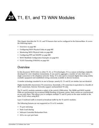
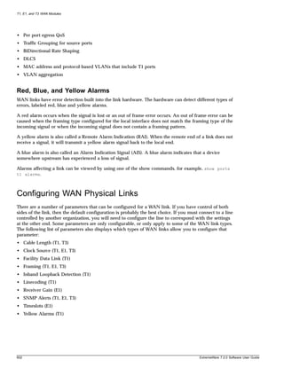
![Configuring WAN Physical Links
Cable Length
Longer cable lengths cause greater losses for signals, so transmitter hardware must transmit at a higher
level to transmit data successfully. However, too high a signal level can cause crosstalk from one cable
to another. The cablelength parameter allows you to control the transmitter signal level for your
conditions. Typically, your service provider will suggest the correct level.
The parameter values available differ for T1 and T3 links. For E1, the parameter value is not changeable,
but is always set to 120 Ohms. However, for E1 links you can configure the receiver gain to meet your
conditions. See “Receiver Gain” on page 605.
For short haul connections (less than 1000 feet) the typical equipment uses less sensitive receivers. The
transmitter level for T1 is set by selecting a cable length in feet, from the following values: 133, 266, 399,
533 or 655. For T3, select from the following values: 249 or 900. Choose the next higher value if the cable
length provided by your service provider does not match one of these values. For example, choose 133
for a 50 foot cable and 533 for a 450 foot cable. The default value is 133, which corresponds to cables in
the range of 0-133 feet.
For longer distances (up to 6000 feet) T1 equipment uses more sensitive receivers, and crosstalk is more
likely to occur. Under these conditions, the transmitter level is set by selecting a transmitter attenuation
level in dB from the following values: -22.5, -15, -7.5, or 0.
From lowest to highest transmitter level, use the following values for the configure ports t1
cablelength command: -22.5 db, -15 db, -7.5 db, 0 db, 133 feet, 266 feet, 399 feet, 533 feet, and 655 feet.
To configure the cable length, use one of the following commands:
configure ports <portlist> t1 cablelength [[0 | -7.5 | -15 | -22.5] db | [133 | 266 |
399 | 533 | 655] feet]
configure ports <portlist> t3 cablelength [349 | 900] feet
Clock Source
A clock is used to synchronize data transmission on the line. Generally, one end of the link provides the
master clock, and the other end of the link recovers the clock from the signal on the line. By default the
clock source is derived from the line. If needed, an internal clock is available. To configure the clock
source, use the following command:
configure ports <portlist> [t1 | e1 | t3] clock source [internal | line]
NOTE
If the clock source is configured as “line”, but the clock cannot be recovered from the signal on the line,
the hardware will use the internal clock instead.
Facility Data Link
Facility data link (FDL) for T1 links uses twelve bits in the ESF frame to signal information about line
and connection status. Since FDL is only meaningful for ESF framing, FDL settings are ignored when a
port is configured for SF framing. See “Inband Loopback Detection” for information on configuring
framing.
ExtremeWare 7.2.0 Software User Guide 603](https://image.slidesharecdn.com/extremewareuserguide72-110124002726-phpapp01/85/Extreme-wareuserguide72-603-320.jpg)
![T1, E1, and T3 WAN Modules
The two T1 standards supported for FDL are ATT, described by the ATT 54016 specification, and ANSI,
described by the T1.403 standard. The default value is off. To configure FDL, use the following
command:
configure ports <portlist> t1 fdl [off | att | ansi]
Framing
Framing is used to synchronize data transmission on the line. Framing allows the hardware to
determine when each packet starts and ends. The two choices for T1 framing are Super Frame (SF), also
known as D4, and Extended Super Frame (ESF). The ESF scheme is a newer standard and is enabled by
default. To choose the T1 framing scheme, use the following command:
configure ports <portlist> t1 framing [esf | sf]
If you choose to use SF framing, you should disable yellow alarm detection for the T1 line. SF framing
may generate false yellow alarms. See “Yellow Alarms” on page 605 for more details.
The framing choices for E1 are CRC4 or no-CRC4. To choose the E1 framing scheme, use the following
command:
configure ports <portlist> e1 framing [crc4 | no-crc4]
The framing choices for T3 are C-bit and M13. To choose the T3 framing scheme, use the following
command:
configure ports <portlist> t3 framing [c-bit | m13]
Inband Loopback Detection
When inband loopback detection is enabled, a specific sequence of data in the signal payload from the
remote end of the T1 link will cause the local end to enter network line loopback mode and send any
received signal back to the remote end. Inband loopback detection is only possible if the FDL standard
is configured as ATT. See “Facility Data Link” on page 603 for more details. By default, inband loopback
detection is off. See “Loopback” on page 606 for more information about loopback modes. To configure
inband loopback detection, use the following command:
configure ports <portlist> t1 lbdetect [off | inband]
Linecoding
Linecoding is the convention used to encode signals for transmission over the line.
For T1 connections you can choose from two linecoding standards, bipolar eight zero suppression
(B8ZS) or alternate mark inversion (AMI). The default value is B8ZS. To configure linecoding, use the
following command:
configure ports <portlist> t1 linecoding [b8zs | ami]
604 ExtremeWare 7.2.0 Software User Guide](https://image.slidesharecdn.com/extremewareuserguide72-110124002726-phpapp01/85/Extreme-wareuserguide72-604-320.jpg)
![Configuring WAN Physical Links
Receiver Gain
The receiver gain for E1 links can be configured to improve performance of the link. Changing the
receiver gain can help to receive the E1 signal or to reduce crosstalk. Receiver gain is only configurable
for E1 links. To configure receiver gain, use the following command:
configure ports <portlist> e1 receivergain [-12 | -43] db
SNMP Alerts
If the WAN module hardware detects a red, yellow, or blue alarm, the alarms are displayed by using a
show command. Additionally, the module can be configured to send an SNMP alert to the SMMi in the
switch when red, yellow, or blue alarms are detected. If the module is configured to send SNMP alerts,
and the switch is configured to send SNMP trap messages, then the switch will send a message to any
SNMP trap receivers that have been configured. To configure SNMP trap receivers, and for more
information about configuring SNMP in ExtremeWare, see Chapter 3.
The module can also be configured not to send an SNMP alert to the SMMi. Any red, yellow, or blue
alarms will not be reported to the SNMP trap receivers. The default value for SNMP alerts is enabled.
To configure whether SNMP alerts are generated from WAN alarms, use the following command:
configure ports <portlist> [t1 | e1 | t3] snmp alert [enable | disable]
Timeslots
The E1 signal is divided into thirty-two timeslots, numbered 0 through 31. The first timeslot (0) is
reserved and cannot be used to transmit data. The timeslot numbered 16 is often used for voice phone
calls in installations that combine voice and data. For installations that use the full E1 bandwith for data
communications, you will not need to configure which timeslots are used. For installations that do not
use the total E1 bandwith, your E1 provider will tell you which timeslots to use.
To configure which timeslots to use for your E1 link, use the following command:
configure ports <portlist> e1 timeslots <timeslots>
A timeslot list uses a dash to represent a range of numbers and a comma to separate single numbers or
ranges. Valid timeslots range from 1 to 31. For example, to specify timeslots 1 through 15 and 17
through 31 for the E1 port 1 on slot 4, use the following command:
configure ports 4:1 e1 timeslots 1-15,17-31
Yellow Alarms
A yellow alarm occurs on a device when its signal is not received at the remote end. It is also called a
Remote Alarm Indication (RAI). You can disable detection and generation of yellow alarms for a T1
port. When SF framing is used, yellow alarm detection and generation should be set to off, because
detection of yellow alarms is not reliable when data traffic is transmitted with SF framing (data traffic
often contains bit combinations that do not occur for encoded voice traffic). The default value for yellow
alarm generation and detection is both. To configure yellow alarms, use the following command:
configure ports <portlist> t1 yellow [detection | generation | both | off]
ExtremeWare 7.2.0 Software User Guide 605](https://image.slidesharecdn.com/extremewareuserguide72-110124002726-phpapp01/85/Extreme-wareuserguide72-605-320.jpg)
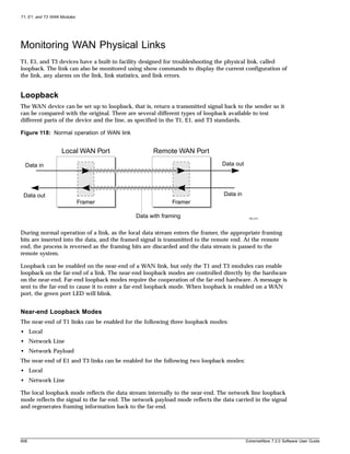
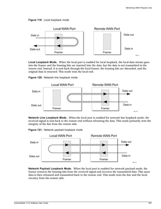
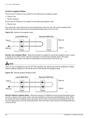
![Configuring PPP and MLPPP
Enabling Loopback Mode
To enable a local loopback mode, use one of the following commands:
enable ports <portlist> [t1 | e1 | t3] loopback [local | network line]
enable ports <portlist> t1 loopback network payload
To enable a remote loopback mode, use the following command:
enable ports <portlist> [t1 | t3] loopback remote [line | payload | loopdown]
Disabling Loopback Mode
Use the following command to return the near and remote side of a T1, E1 or T3 link from loopback
mode to normal mode:
disable ports <portlist> [t1 | e1 | t3] loopback
You can also use the following command to return the remote T1 or T3 port to normal function from
loopback mode:
enable ports <portlist> [t1 | t3] loopback remote [line | payload | loopdown]
Configuring PPP and MLPPP
Point-to-Point Protocol (PPP) is used across the entire range of communication speeds and devices
found on the internet. Typically, PPP uses Layer 3 to connect two broadcast networks, say two Ethernet
LANs, into a single WAN by transporting IP packets over a link. PPP can also use Layer 2 to bridge
VLAN traffic.
Multilink PPP (MLPPP) is a protocol for combining a number of PPP links into one bundle that
transports traffic over the links in the bundle. Multilink PPP is supported for T1 and E1 technologies in
ExtremeWare, but not for T3. Instead, a T3 link is configured as a single PPP link.
A multilink group is a bundle of individual PPP links that are configured to work together as a single
link. With a multilink group configured, it is easy to add or remove PPP links in order to provide
appropriate bandwidth. The multilink group balances traffic among the individual PPP links and
properly sequences packets across the multilink group.
Typically, you would create a multilink group, configure the multilink group by adding T1 or E1 ports
and configuring PPP/MLPPP parameters, add the multilink group to a VLAN, and finally, enable the
multilink group.
For a T3 port, you would configure its PPP parameters and add it to a VLAN.
This section covers the following topics:
• Multilink PPP and Multilink Groups on page 610
• Configuring a PPP/MLPPP Link on page 610
ExtremeWare 7.2.0 Software User Guide 609](https://image.slidesharecdn.com/extremewareuserguide72-110124002726-phpapp01/85/Extreme-wareuserguide72-609-320.jpg)
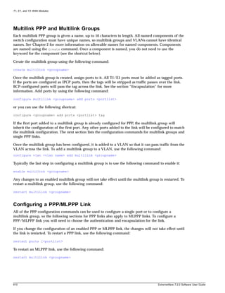
![Configuring PPP and MLPPP
Authentication
By default, no authentication is configured on PPP links since the WM-4T1i module will typically be
used with leased lines—where both sides of the link are controlled and authentication is not required. If
authentication is needed, the WM-4T1i module supports either PAP or CHAP. Password authentication
protocol (PAP) authenticates a user as the connection is established by sending a username and
password. Challenge Handshake Authentication Protocol (CHAP) authenticates a user by sending a
challenge across the link. The remote end calculates a response based on the user password and sends
the response back across the link. CHAP is a more secure authentication protocol than PAP. The link can
also be configured to attempt to use CHAP first, followed by PAP, if CHAP fails.
To configure authentication on a PPP link, use the following command:
configure ppp authentication [off | chap | pap | chap-pap] [ports <portlist> |
multilink <groupname>]
PPP Link Username. When the local end of a link initiates a PPP connection, the local end must send
the appropriate authentication information. For PAP it sends the username and password, for CHAP it
sends the username and must respond correctly to the challenge, and for no authentication it sends
nothing. To configure the username and password used to initiate the link, use the following command:
configure ppp user <name> {encrypted} {<password>} [ports <portlist> | multilink
<groupname>]
The encrypted keyword is used to hide the password when the switch configuration is displayed; it
does not control whether the password is encrypted across the link during authentication.
PPP User Accounts. When the remote end initiates the link, the local end must verify the
authentication information. The local end maintains a list of authorized user accounts and passwords.
To add a user to the list, use the following command:
create account pppuser <username> {encrypted} {<password>}
Encapsulation
The packets passed over the PPP/MLPPP link can use either bridged or routed encapsulation. You
would use bridged packets if you plan to have VLANs span the link. You would use routed packets if
the link connects two different routed networks or separate VLANs.
Using bridged packets allows the VLAN tags to be carried across the PPP/MLPPP link. Bridged packets
are transported using the PPP Bridging Control Protocol (BCP), described in RFC 2878, except in the
case of Legacy BCP, described below. When the encapsulation is set to BCP, 802.1Q and 802.1p
information is preserved and transported across the link.
Routed packets are transported across a PPP/MLPPP link using IP Control Protocol (IPCP), described in
RFC 1332. This is the encapsulation that is familiar to most users of PPP. The routed packets do not
contain Ethernet headers so cannot preserve VLAN tags. However, the WAN ports still must be added
as tagged ports to the VLAN that contains them. The module uses the tags internally and strips them
off before the packets are transmitted. The IP addresses used for the PPP/MLPPP link are taken from
the IP address assigned to the VLAN at each end of the link. The VLAN that contains the IPCP
encapsulated PPP/MLPPP ports cannot contain other ports. In other words, the only ports allowed in
the VLAN are those that make up the IPCP encapsulated link. There can only be one VLAN spanning
an IPCP-encapsulated link.
ExtremeWare 7.2.0 Software User Guide 611](https://image.slidesharecdn.com/extremewareuserguide72-110124002726-phpapp01/85/Extreme-wareuserguide72-611-320.jpg)
![T1, E1, and T3 WAN Modules
You must have one and only one encapsulation type configured on a PPP/MLPPP link. Setting BCP
encapsulation off implies that IPCP encapsulation is on. The default setting is BCP encapsulation on and
IPCP encapsulation off. To configure encapsulation, use the following command:
configure ppp [bcp [on | off] | ipcp [on | off]] [ports <portlist> | multilink
<groupname>]
Legacy BCP. Some routers supported by other vendors implemented BCP using an older standard,
RFC 1638. For interoperability, the Extreme Networks implementation supports both standards. The
limitation with RFC 1638-based BCP is that 802.1Q tags are not supported. So Legacy BCP cannot
support multiple VLANs or preserve 802.1p priority across the PPP link. Both types of BCP can operate
over single and multilink PPP.
When BCP is negotiated over a link, RFC 2878 BCP is initially proposed. If the peer only supports
Legacy BCP (RFC 1638), then the link is made using Legacy BCP. Since the WAN module ports are
always configured as tagged ports, the VLAN tag is removed in the egress direction and inserted in the
egress direction when BCP is operating in Legacy mode.
There is no Legacy BCP specific configuration, and the display for the command show ppp info is
identical for BCP and Legacy BCP. To determine if the link is using Legacy BCP, use the following
command:
show log warning
and look for the message:
BCP: Legacy BCP UP;Only a single VLAN over BCP is supported
612 ExtremeWare 7.2.0 Software User Guide](https://image.slidesharecdn.com/extremewareuserguide72-110124002726-phpapp01/85/Extreme-wareuserguide72-612-320.jpg)
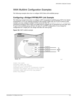
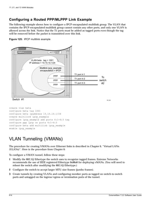
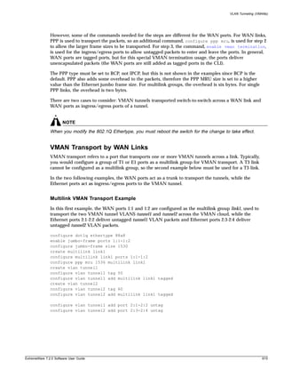
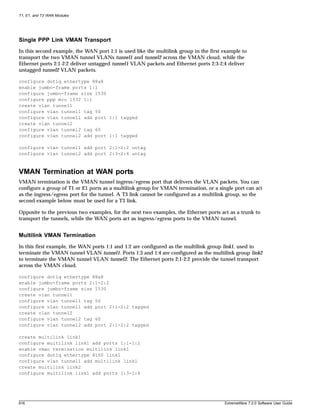
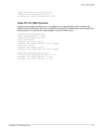

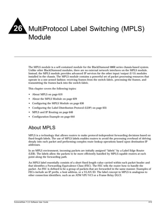
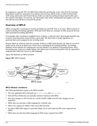
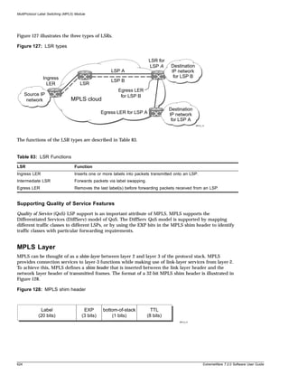
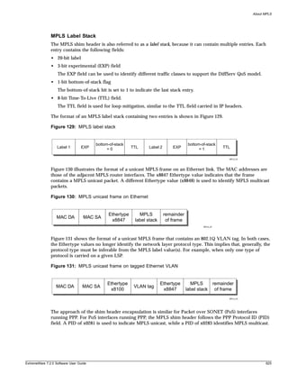
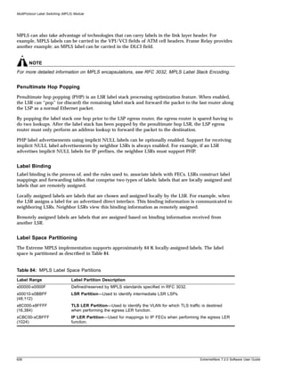
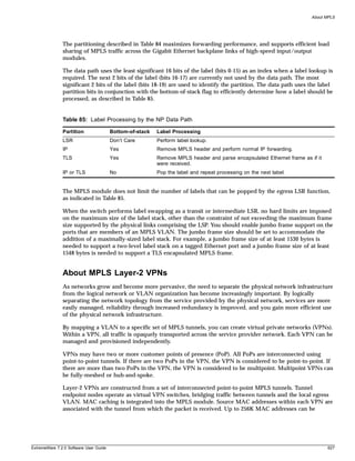
![MultiProtocol Label Switching (MPLS) Module
Configuring the MPLS Module
This section describes how to configure the MPLS module. For hardware installation information for the
BlackDiamond 6800 series switch, see the Extreme Networks Consolidated Hardware Guide.
NOTE
Documentation for Extreme Networks products is available at the Extreme Networks home page at
http://www.extremenetworks.com/.
This section describes how to configure:
• MPLS interfaces
• LDP
• OSPF support
• QoS support
• Filter support
Configuring MPLS Interfaces
To configure MPLS interfaces, first enable MPLS on the router by using the following command:
enable mpls
Next, enable MPLS on a specific VLAN or on all VLANs, using the following command:
configure mpls add vlan [<vlan name> | all] {ldp | rsvp-te}
MPLS must be enabled on all VLANs that transmit or receive MPLS-encapsulated frames. Using the
configure mpls add vlan command causes the LDP neighbor discovery process to begin on the
specified VLAN.
NOTE
The specified VLAN must be configured with an IP address, and have IP forwarding enabled. IGMP
snooping must also be enabled on the switch.
If all VLANs are selected, MPLS is enabled on all VLANs that have an IP address and IP forwarding
enabled. This command optionally enables LDP or RSVP-TE for the specified VLAN. If not specified,
both LDP and RSVP-TE are enabled on the specified VLAN.
If you have enabled MPLS on an OSPF interface that is used to reach a particular destination, make sure
that you enable MPLS on all additional OSPF interfaces that can reach that same destination (for
example, enable MPLS on all VLANs that are connected to the backbone network).
Configuring the Maximum Transmission Unit Size
After you have enabled MPLS, you can configure the maximum transmission unit (MTU) size using the
following command:
configure mpls vlan [<vlan name> | all] ip-mtu <number>
630 ExtremeWare 7.2.0 Software User Guide](https://image.slidesharecdn.com/extremewareuserguide72-110124002726-phpapp01/85/Extreme-wareuserguide72-630-320.jpg)
![Configuring the MPLS Module
This command configures the IP MTU for frames transmitted onto MPLS LSPs via the specified egress
VLAN. The default settings is 1496 bytes. If all is selected, the configuring MTU applies to all
MPLS-enabled VLANs.
This command applies to the ingress LSR only when a received IP packet is destined for an MPLS LSP.
In this case, if the length of the IP packet exceeds the configured MTU size for the egress VLAN and the
Don’t Fragment (DF) bit is not set in the IP header of the packet, the packet is fragmented before it is
forwarded onto an MPLS LSP. If the DF bit is set in the packet header, Path MTU Discovery starts.
Fragmentation is based on either the minimum value of the configured MPLS IP MTU size or the
configured IP MTU size for the egress VLAN. (The IP MTU size is configured using the configure
ip-mtu <number> vlan <vlan name> command.)
You should configure the MPLS IP MTU so that the addition of the MPLS label stack the link layer
header does not cause the packet to be too large to be transmitted on the egress ports. To avoid
potential problems, you should enable jumbo frame support on all ports that are members of an MPLS
VLAN.
Configuring the Propagation of IP TTL
To enable or disable the propagation of the IP time-to-live (TTL) function, use the following command:
configure mpls propagate-ip-ttl [enabled | disabled]
This command enables and disables the propagation of the IP TTL value for routed IP packets. The
default setting is enabled.
NOTE
You must maintain identical propagate-ip-ttl settings on all LERs in the MPLS domain. Not doing so
may cause packets to loop endlessly and not be purged from the network if a routing loop is
inadvertently introduced.
When propagate-ip-ttl is disabled, the LSP is viewed as a point-to-point link between the ingress
LSR and the egress LSR. Intermediate LSRs in the MPLS network are not viewed as router hops (from
an IP TTL perspective). In this case, the IP TTL is decremented once by the ingress LSR and once by the
egress LSR. When disabled, the MPLS TTL is set to 255 by the ingress LSR and is independent of the IP
TTL.
When propagate-ip-ttl is enabled, each LSR is viewed as a router hop (from an IP TTL perspective).
When a packet traverses an LSP, it emerges with the same TTL value that it would have had if it had
traversed the same sequence of routers without being label-switched. When enabled, the MPLS TTL
field is initially set by the IP TTL field at the ingress LSR, and the IP TTL field is set to the MPLS TTL
by the egress LSR.
Configuring Penultimate Hop Popping
To enable or disable PHP, use the following command:
configure mpls php [enabled | disabled]
This command enables or disables whether PHP is requested by the egress LER.
When PHP is enabled, PHP is requested on all LSPs for which the switch is the egress LER.
ExtremeWare 7.2.0 Software User Guide 631](https://image.slidesharecdn.com/extremewareuserguide72-110124002726-phpapp01/85/Extreme-wareuserguide72-631-320.jpg)
![MultiProtocol Label Switching (MPLS) Module
PHP is requested by assigning the Implicit Null Label in an advertised mapping. PHP is always
performed when requested by an egress LSR (for example, when the switch is acting as an intermediate
LSR). The Implicit Null Label is always used in conjunction with routes exported by OSPF, regardless of
the PHP configuration.
This command can only be executed when MPLS is disabled. The default setting is disabled.
Configuring QoS Mappings
To configure QoS mappings, use the following command:
configure mpls qos-mapping [dot1p-to-exp | exp-to-dot1p] [all |
<input_value>]/<output_value>
This command configures MPLS QoS mappings. If all is specified, all input values are mapped to the
specified <output_value>. The valid range of integers for the <input_value> and the <output_value>
is 0 to 7. By default, the mapping tables are initialized such than an <input_value> of n is mapped to
an <output_value> of n.
Two mappings are supported:
• dot1p-to-exp
• exp-to-dot1p
Dot1p-to-exp Mappings
The dot1p-to-exp mappings are used by the ingress LSR. When a non-MPLS ingress frame arrives at the
MPLS module, the frame always contains an IEEE 802.1p priority field.
The value of the priority field is set based on the QoS classification performed by the ingress I/O
module. The ingress I/O modules assign each packet to a hardware queue, based on the configured
ExtremeWare QoS policies. There is a one-to-one mapping between the hardware queue and the 802.1p
priority values that are inserted into frames forwarded to the MPLS module. For example, the 802.1p
priority value is set to 0 for frames forwarded from hardware queue 0, set to 1 for frames forwarded
from hardware queue 1, and so on.
The dot1p-to-exp table maps 802.1 priority values to MPLS EXP values. The table is completely flexible,
such that any 802.1p priority <input_value> can be mapped to any EXP <output_value>. The EXP
output_value is set in the MPLS header of the packet as it is forwarded to the MPLS network.
Exp-to-dot1p Mappings
The exp-to-dot1p mappings are used when the switch performs label swapping as an intermediate LSR
and when the switch is the egress LSR. In both of these cases, the MPLS module receives an
MPLS-encapsulated frame.
The EXP field in the frame is used as an <input_value> to the exp-to-dot1p table. The corresponding
<output_value> is an 802.1p priority value. The 802.1p priority value is inserted into the frame before
the frame is forwarded by the MPLS module.
The exp-to-dot1p table is completely flexible, such that any EXP <input_value> can be mapped to any
802.1p priority <output_value>.
632 ExtremeWare 7.2.0 Software User Guide](https://image.slidesharecdn.com/extremewareuserguide72-110124002726-phpapp01/85/Extreme-wareuserguide72-632-320.jpg)
![Configuring the MPLS Module
The exp-to-dot1p table is also used by Packet over SONET (PoS) ports when classifying
MPLS-encapsulated packets received from the SONET link. When a PoS port receives an
MPLS-encapsulated packet from the SONET link, the packet is classified based on the EXP value in the
MPLS shim header. The EXP value from the received frame is used as an index into the exp-to-dot1p
mapping table to retrieve and 802.1p priority value. The frame is then assigned to a QoS profile, based
on the retrieved 802.1p priority value. The mappings between 802.1p priority values and QoS profiles
are configured using the following command:
configure dot1p type
NOTE
For more information on QoS, see Chapter 8. For more information on the PoS module, see
Chapter 24.
Resetting MPLS Configuration Parameter Values
To reset MPLS configuration parameters to their default values, use the following command:
unconfigure mpls
This command resets the following configuration parameters:
• IP-MTU
• LDP propagation filter settings on all VLANs
• LDP advertisement filter settings
• LDP session timers
• RSVP-TE interface parameters
• RSVP-TE profile parameters
• Settings for propagate-ip-ttl
• QoS mapping tables
To restore the default values for the QoS mapping tables, use the following command:
unconfigure mpls qos-mapping [dotp-to-exp | exp-to-dot1p | lsp <lsp_name>]
The default contents of either QoS mapping table maps an input value of n to an output value of n.
Displaying MPLS Configuration Information
You can display MPLS information about the following topics:
• MPLS configuration information for the entire switch or for a specific VLAN
• MPLS forwarding entry information
• MPLS LDP peer information
• MPLS RSVP-TE peer information
• MPLS label mapping information
• MPLS QoS mapping information
ExtremeWare 7.2.0 Software User Guide 633](https://image.slidesharecdn.com/extremewareuserguide72-110124002726-phpapp01/85/Extreme-wareuserguide72-633-320.jpg)
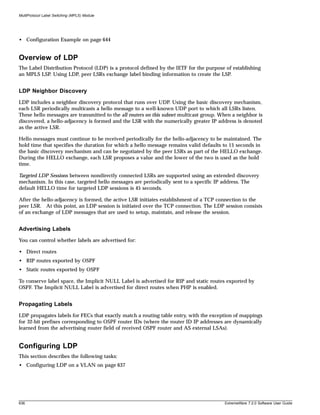
![Configuring the Label Distribution Protocol (LDP)
• Configuring LDP Filters on page 637
• Configuring LDP Session Timers on page 638
• Restoring LDP Session Timers on page 639
• Displaying LDP Peer Information on page 639
Configuring LDP on a VLAN
To configure LDP on a VLAN, use the following command:
configure mpls add vlan [<vlan name> | all] {ldp | rsvp-te}
This command enables LDP on one of all VLAN. If not specified, both LDP and RSVP-TE are enabled
on the specified VLAN.
To disable LDP on a VLAN, use the following command:
configure mpls delete vlan [<vlan name> | all] {ldp | rsvp-te}
This command disables LDP on one or all VLANs. This command terminates all LDP sessions and all
established LDP LSPs.
Configuring LDP Filters
You can configure two types of LDP filters:
• Label propagation filters
• Label advertisement filters
Configuring an LDP Label Propagation Filter. To configure an LDP label propagation filter, use the
following command:
configure mpls vlan [<vlan name> | all] ldp propagate [all | none | route-map
<route_map>]
This command configures a filter to be used by LDP when propagating unsolicited label mappings to
all LDP neighbors on the specified VLAN. If all VLANs are selected, the settings of this command apply
to all MPLS-enabled VLANs.
You can configure the propagation filter, as follows:
• all—Unsolicited label mappings are propagated to the VLAN. This is the default setting.
• none—No unsolicited label mappings are propagated to the VLAN.
• route-map <route_map>—The specified route map is used to permit or deny the propagation of
unsolicited label mappings to the VLAN.
The only supported route map match operation keyword is nlri-list. If selected, the access_profile
parameter of the nlri-list keyword is compared to the FEC that is associated with each label
mapping.
NOTE
For more information on route maps, see Chapter 12.
ExtremeWare 7.2.0 Software User Guide 637](https://image.slidesharecdn.com/extremewareuserguide72-110124002726-phpapp01/85/Extreme-wareuserguide72-637-320.jpg)
![MultiProtocol Label Switching (MPLS) Module
Configuring an LDP Label Advertisement Filter. To configure an LDP label advertisement filter, use
the following command:
configure mpls ldp advertise [direct | rip | static] [all | none | route-map
<route_map>]
This command configures a filter to be used by LDP when originating unsolicited label mapping
advertisements to LDP neighbors.
You can configure how the advertisement filter is applied, as follows:
• direct—The advertisement filter is applied to the FECs associated with direct routes exported by
OSPF.
• rip—The advertisement filter is applied to the FECs associated with RIP routes exported by OSPF.
• static—The advertisement filter is applied to the FECs associated with static routes exported by
OSPF.
You can configure the advertisement filter, as follows:
• all—All unsolicited label mappings are originated for all routes of the specified type (direct, RIP, or
static). This is the default setting for direct routes.
• none—No unsolicited label mappings are originated for all routes of the specified type. This is the
default setting for RIP and static routes.
• route-map <route_map>—The specified route map is used to permit or deny the origination of
unsolicited label mappings for all routes of the specified type.
The only supported route map match operation keyword is nlri-list. If selected, the access_profile
parameter of the nlri-list keyword is compared to the FEC that is associated with each route.
RIP and static routes are advertised with the Implicit NULL label and direct routes are advertised with
an MPLS label, unless PHP is enabled.
You can control the number of labels advertised using the configure mpls ldp advertise command.
Advertising labels for a large number of routes may increase the required number of labels that must be
allocated by LSRs. Take care to insure that the number of labels advertised by LERs does not
overwhelm the label capacity of the LSRs.
Configuring LDP Session Timers
To configure LDP session timers, use the following command:
configure mpls [ldp | targeted-ldp] [hello | keep-alive] <hold_time> <interval_time>
LDP session timers are separately configurable for LDP and targeted LDP sessions. The hello
<hold_time> <interval_time> parameter specifies the amount of time (in seconds) that a hello
message received from a neighboring LSR remains valid. If a hello message is not received from a
particular neighboring LSR within the specified hello <hold_time>, the hello-adjacency is not
maintained with that neighboring LSR.
The session keep-alive <hold_time> <interval_time> parameter specifies the time (in seconds)
during which an LDP message must be received for the LDP session with a particular peer LSR to be
maintained. If an LDP PDU is not received within the specified session keep-alive <interval_time>,
the corresponding LDP session is torn down.
638 ExtremeWare 7.2.0 Software User Guide](https://image.slidesharecdn.com/extremewareuserguide72-110124002726-phpapp01/85/Extreme-wareuserguide72-638-320.jpg)
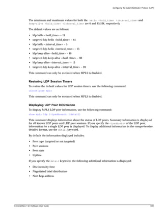
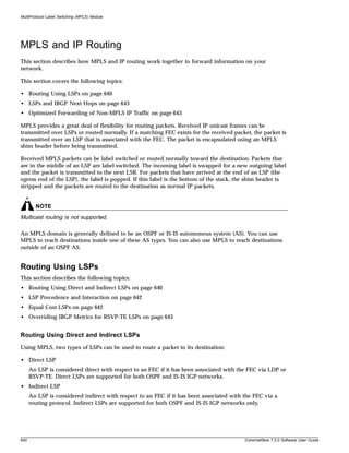
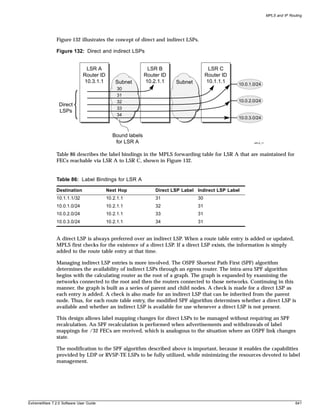
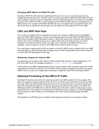
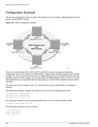
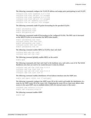
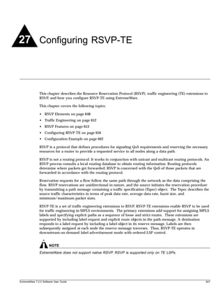
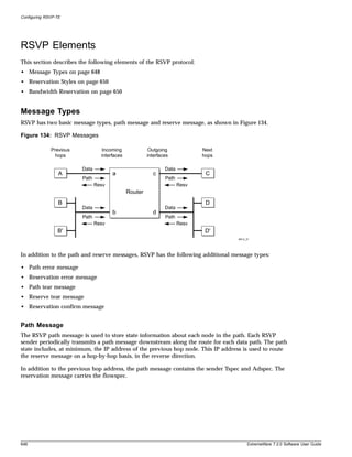
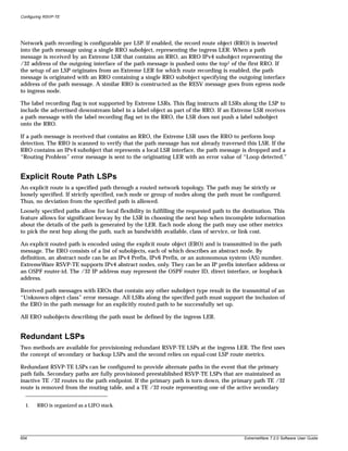
![RSVP Features
paths is installed as the preferred path for the LSP. If multiple secondary are paths available, the
secondary path is randomly selected. If the primary path is reestablished, the primary path TE /32
route is reinstalled as the preferred path.
Stateful failovers can be managed by configuring only secondary paths for an LSP. When no primary
paths are configured for an LSP, a TE /32 route representing one of the secondary paths is installed in
the route table. If the secondary path fails, for which a TE /32 route has been installed in the route
table, another secondary TE /32 route representing separate path is installed in the route table
(provided one is configured and active). Secondary path TE /32 routes remain the preferred route
unless a primary path is configured for the LSP, the active secondary path fails, or the active secondary
path is deleted. Thus, no switch-back to the original secondary path is performed if the original
secondary path fails and is later reestablished.
Parallel RSVP-TE LSPs can exist to the same endpoint. Parallel LSPs exist when multiple paths are
configured to the same egress LSR, with each LSP having a configured metric that is less than, or equal
to, the interior gateway protocol (IGP) metric. In both cases, a TE /32 route to the egress LER is
installed in the route table of the ingress LER for all of the best equal-cost RSVP-TE paths. Traffic is
distributed across up to four TE /32 routes based on a MAC and IP address hash algorithms. If one of
the LSPs fail, the traffic is redistributed across the remaining active LSPs. In this example, no LSP
secondary paths are required.
Ping Health Checking
After an LSP has been established, the egress LSR may be optionally pinged to determine end-to-end
path connectivity. If a ping response is not received within [2 * ping-interval – 1] seconds, the LSP is
considered unavailable. You can specify how frequently an ICMP echo request is transmitted to the
egress LER IP address on the established LSP.
Improving LSP Scaling
You can improve LSP scaling by configuring the following RSVP-TE parameters:
• refresh-time—The refresh-time specifies the interval for sending refresh path messages. RSVP
refresh messages provide soft state link-level keep-alive information for previously established paths
and enable the switch to detect when an LSP is no longer active. RSVP sessions are torn down if an
RSVP refresh message is not received from a neighbor within [(keep-multiplier + 0.5) * 1.5 *
refresh-time] seconds. The valid refresh-time may be set to any value between one and 36000 seconds.
The default setting is 30 seconds. Configuring a longer refresh time reduces both switch and network
overhead.
• summary-refresh-time—The summary-refresh-time, specified in tenths of a second, indicates the
time interval for sending summary refresh RSVP messages. The summary-refresh-time must be less
than the configured refresh-time. The default summary-refresh-time is zero, indicating that no
summary refresh RSVP messages are sent. The summary-refresh-time value may be set to any value
between zero to 100 (or 10 seconds). If configured, the bundled and summary refresh RSVP
messages are only sent to RSVP-TE peers supporting RSVP refresh reduction.
• bundle-time—The bundle-time, specified in tenths of a second, indicates the maximum amount of
time a transmit buffer is held so that multiple RSVP messages can be bundled into a single PDU. The
default bundle-time is zero, indicating that RSVP message bundling is not enabled. The bundle-time
value can be set to any value between zero and 30 (or 3 seconds).
ExtremeWare 7.2.0 Software User Guide 655](https://image.slidesharecdn.com/extremewareuserguide72-110124002726-phpapp01/85/Extreme-wareuserguide72-655-320.jpg)
![Configuring RSVP-TE
Configuring RSVP-TE
This section describes the following tasks:
• Configuring RSVP-TE on a VLAN on page 656
• Configuring RSVP-TE Protocol Parameters on page 656
• Configuring an RSVP-TE Path on page 657
• Configuring an Explicit Route on page 658
• Configuring an RSVP-TE Profile on page 659
• Configuring an Existing RSVP-TE Profile on page 660
• Configuring an RSVP-TE LSP on page 660
• Adding a Path to an RSVP-TE LSP on page 661
• Displaying RSVP-TE LSP Configuration Information on page 661
• Displaying the RSVP-TE Routed Path on page 662
• Displaying the RSVP-TE Path Profile on page 662
• Displaying the RSVP-TE LSP on page 662
Configuring RSVP-TE on a VLAN
To configure RSVP-TE on one or all VLANs, use the following command:
configure mpls add vlan [<vlan name> | all] {ldp | rsvp-te}
To disable RSVP-TE on a VLAN, use the following command:
configure mpls delete vlan [<vlan name> | all] {ldp | rsvp-te}
This command disables RSVP-TE on one or all VLANs. Deleting RSVP-TE causes all TE LSPs to be
released, and prevents TE LSPs from being established or accepted on the specified VLAN.
Configuring RSVP-TE Protocol Parameters
To configure RSVP-TE protocol parameters, use the following command:
configure mpls rsvp-te vlan [<vlan name> | all] {hello-interval <seconds>}
{refresh-time <seconds>} {summary-refresh-time <tenth-seconds>} {bundle-time
<tenth-seconds>} {keep-multiplier <number>}
This command configures the RSVP-TE protocol parameters for the specified VLAN. The RSVP-TE
keyword all indicates that the configuration changes apply to all RSVP-TE enabled VLANs.
The hello-interval time specifies the RSVP hello packet transmission interval. The RSVP hello packet
is used by the switch to detect when a RSVP-TE peer is no longer reachable. If an RSVP hello packet is
not received from a peer with [hello-interval * keep-multiplier] seconds, the peer is declared down
and all RSVP sessions to and from that peer are torn down. The default hello-interval time is zero,
indicating that RSVP hellos are not enabled. The hello-interval may be set to any value between zero
and 60 seconds.
The refresh-time parameter specifies the interval for sending refresh path messages. RSVP refresh
messages provide “soft state” link-level keep-alive information for previously established paths and
656 ExtremeWare 7.2.0 Software User Guide](https://image.slidesharecdn.com/extremewareuserguide72-110124002726-phpapp01/85/Extreme-wareuserguide72-656-320.jpg)
![Configuring RSVP-TE
enables the switch to detect when an LSP is no longer active. RSVP sessions are torn down if an RSVP
refresh message is not received from a neighbor within [(keep-multiplier + 0.5) * 1.5 * refresh-time]
seconds. The default refresh-time is 30 seconds and the default keep-multiplier value is three. The
minimum and maximum refresh-time values are one and 36,000 seconds (or ten hours) respectively.
The minimum and maximum keep-multiplier values are one and 255 respectively.
The bundle-time, specified in tenths of a second, indicates the maximum amount of time a transmit
buffer is held so that multiple RSVP messages can be bundled into a single PDU. The default
bundle-time is zero, indicating that RSVP message bundling is not enabled. The bundle-time value
may be set to any value between zero and 30 (or 3 seconds).
The summary-refresh-time, specified in tenths of a second, indicates the time interval for sending
summary refresh RSVP messages. The summary-refresh-time must be less than the configured
refresh-time. The default summary-refresh-time is zero, indicating that no summary refresh RSVP
messages are sent. The summary-refresh-time value may be set to any value between zero to 100 (or
10 seconds).
If configured, the bundled and summary refresh RSVP messages are only sent to RSVP-TE peers
supporting RSVP refresh reduction.
Configuring an RSVP-TE Path
To add an RSVP-TE routed path, use the following command:
configure mpls rsvp-te add path <path_name> [<ipaddress> | <host_name>] {from
<local_endpoint_vlan>}
The <path_name> and <ipaddress> or <host_name> must be specified for the path. The <path_name>
parameter is a character string that is to used to identify the path within the switch. The <path_name>
string must begin with an alphabetic character, and may contain up to 31 additional alphanumeric
characters. Each <path_name> represents a routed path to a single IP destination.
If the <host_name> is specified, the DNS client on the switch must be configured so that the
<host_name> can first be resolved to an IP address. Alternate routed paths to the same IP destination
may be configured by adding additional <path_names> and specifying the same <ipaddress> or
<host_name> as the path endpoint.
The RSVP-TE path is not signaled until an LSP is added with the specified <path_name>. If no explicit
route objects are configured, the path will follow the best-routed path to the configured <ipaddress>
(or IP address obtained from DNS name resolution). Optionally, the from keyword can be used to
specify the <local_endpoint_vlan> from which the path is signaled. The maximum number of
configurable paths is 255.
To delete an RSVP-TE path, use the following command:
configure mpls rsvp-te delete path [<path_name> | all]
This command deletes a configured MPLS RSVP-TE routed path with the specified <path_name>. All
associated configuration information for <path_name> is deleted. A path cannot be deleted as long as
the <path_name> is associated with an LSP. If the all keyword is specified, all paths not associated with
an LSP are deleted.
ExtremeWare 7.2.0 Software User Guide 657](https://image.slidesharecdn.com/extremewareuserguide72-110124002726-phpapp01/85/Extreme-wareuserguide72-657-320.jpg)
![Configuring RSVP-TE
Configuring an Explicit Route
To add an RSVP-TE explicit route, use the following command:
configure mpls rsvp-te path <path_name> add ero [ipaddress <ipaddress/masklength> |
<host_name>] {strict | loose} {order <number>}
This command adds an IP address to the explicit route object (ERO) for the specified path name. The
RSVP-TE routed path may be described by a configured sequence of the LSRs and/or subnets traversed
by the path. Each defined LSR or subnet represents an ERO subobject. Up to 64 subobjects can be added
to each path name.
When specifying an LSR using the <host_name> parameter, the DNS client on the switch must be
configured so that the <host_name> can first be resolved to an IP address. The ipaddress keyword
identifies an LSR using either a /32 address, which may represent an LSR router ID, loopback address,
or direct router interface, or an IP prefix, which represents a directly connected subnet. Each IP address
or prefix is included in the ERO as an IPv4 subobject.
If the IP address is specified as strict, the strict subobject must be topologically1 adjacent to the
previous subobject as listed in the ERO. If the IP address is specified as loose, the loose subobject is not
required to be topologically adjacent to the previous subobject as listed in the ERO. If omitted, the
default subobject attribute is loose. Each IP address or prefix is included in the ERO as an IPv4
subobject.
If the subobject matches a direct router interface or a directly attached subnet, the switch verifies that
the path message is received on the matching router interface. If the LSR specified matches the OSPF
router ID or a configured loopback IP address, the router interface which the packet is received is
ignored.
The LSR path order is optionally specified using the order keyword. The order number parameter is
an integer value from 1 to 65535. IP prefixes with a lower number are sequenced before IP prefixes with
a higher number. You can specify multiple paths and assign them an order number. The order number
determines the path that the LSP follows. Thus, the LSP path follows the configured path of the IP
prefix with the order value from low to high. If the order keyword is not specified, the number value
for the LSR defaults to a value 100 higher than the current highest number value.
If the list of IP prefixes, added to the path, does not reflect an actual path through the network topology,
the path message is returned with an error from a downstream LSR and the LSP is not established.
The order of a configured subobject can not be changed. The ERO subobject must be deleted and
re-added using a different order. If a subobject is added to or deleted from the ERO while the associated
LSP is established, the path is torn down and is resignaled using the new ERO.
Duplicate ERO subobjects are not allowed. Defining an ERO for the path is optional. If you do not
configure an ERO, the path is signaled along the best-routed path and the ERO is not included in the
path message. When the last subobject in the ERO of the path message is reached and the egress IP
node of the path has not been reached, the remaining path to the egress node is signaled along the
best-routed path. Specification of an ERO could lead to undesirable routed paths, so you should be
careful when terminating the ERO routed-path definition prior to the configured path egress node.
1. The LSP next hop matches either the interface IP address or the OSPF router-id of the immediate neighbor
LSR.
658 ExtremeWare 7.2.0 Software User Guide](https://image.slidesharecdn.com/extremewareuserguide72-110124002726-phpapp01/85/Extreme-wareuserguide72-658-320.jpg)
![Configuring RSVP-TE
To delete an RSVP-TE explicit route, use the following command:
configure mpls rsvp-te path <path_name> delete ero [all | ipaddress
<ipaddress/masklength> | <host_name> | order <number>]
This command deletes an LSR or subnet from the ERO for the specified path name. The LSR is specified
using the ipaddress, <host_name>, or order parameter. If an LSR is deleted from an ERO while the
associated LSP is established, the path is torn down and is resignaled using a new ERO. Use the all
keyword to delete the entire ERO from the path name. When there is no configured ERO, the path is no
longer required to take an explicit routed path. The path is then signaled along the best-routed path and
no ERO is included in the path message.
Configuring an RSVP-TE Profile
To add an RSVP-TE profile, use the following command:
configure mpls rsvp-te add profile <profile_name> {bandwidth <bps>} {setup-priority
<priority>} {hold-priority <priority>} {retry-timeout <seconds>} {hop-count <number>}
{ping-interval <seconds>} {metric [<metric> | igp-tracking} {record [enabled |
disabled]}
A profile is a set of attributes that are applied to the LSP when the LSP is configured using the
configure mpls rsvp-te add lsp command. A default profile is provided which cannot be deleted,
but can be applied to any configured LSP. The profile name for the default profile is default. The default
profile parameter values are initially set to their respective default values. The maximum number of
configurable profiles is 255 (one of which is reserved for the default profile).
The bandwidth parameter specifies the desired reserved bandwidth for the LSP. Any positive integer
bps value is valid. Optionally, you can append the characters, k for kilobits, m for megabits, or g for
gigabits, to the bps value to specify the unit of measure. If the k, m, or g, character is omitted, the unit
of measure is assumed to be kilobits. The default bandwidth bps value is zero, which indicates that the
QoS for the LSP is best effort. ExtremeWare does not support bandwidth reservation.
The setup-priority and hold-priority are optional parameters indicating the LSP priority. During
path set up, if the requested bandwidth cannot be reserved through the LSR, the setup-priority
parameter is compared to the hold-priority of existing LSPs to determine if any of the existing LSPs
need to be preempted to allow a higher priority LSP to be established. Lower numerical values
represent higher priorities. The setup-priority range is 0 to 7 and the default value is 7. The
hold-priority range is also 0 to 7 and is set equal to the setup-priority by default. ExtremeWare
does not support LSP preemption.
The retry-timeout keyword specifies the maximum number of seconds the switch allows for LSP
setup. If the LSP cannot be established within retry-timeout seconds, the LSP is resignaled. The
default value for retry-timeout is 30 seconds with a configurable range of 5 to 600 seconds. The
hop-count parameter limits the number of LSRs the path can traverse, including the ingress and egress
router. The default hop-count value is 255 with a configurable range of two to 255.
After an LSP has established, the egress LSR may be optionally pinged to determine end-to-end path
connectivity. If a ping response is not received within [2 * ping-interval – 1] seconds, the LSP is
considered unavailable. The ping-interval keyword specifies how frequently an ICMP echo request is
transmitted to the egress LSR IP address on the established LSP. The default ping-interval is zero,
which indicates no end-to-end LSP health checking is performed. You can set the ping-interval value
to any interval between 0 and 60 seconds.
ExtremeWare 7.2.0 Software User Guide 659](https://image.slidesharecdn.com/extremewareuserguide72-110124002726-phpapp01/85/Extreme-wareuserguide72-659-320.jpg)
![Configuring RSVP-TE
The route metric is used to determine if an established RSVP-TE LSP will actually be used to send
data. Whenever the configured metric is less than, or equal, to the calculated IGP metric, the LSP is
used for sending routed IP traffic. In this case, the LSP is also used to send TLS data when the TLS
tunnel is configured by specifying the tunnel LSP endpoint IP address. Traffic is distributed across up to
four equal-cost LSPs. The valid metric values range from 1 to 65535. Specifying the igp-tracking
keyword forces the route metric to track the underlying IGP metrics. If no IGP metric exists for the LSP
(for example, the LSP traverses a RIP network), the metric is ignored. Tracking IGP metrics is the
default behavior.
The record keyword is used to enable hop-by-hop path recording. The enabled keyword causes the
record route object (RRO) to be inserted into the path message. The RRO is returned in the reserve
message and contains a list of IPv4 subobjects that describe the RSVP-TE path. Path recording by
default is disabled. When disabled, no RRO is inserted into the path message.
To delete an RSVP-TE path profile, use the following command:
configure mpls rsvp-te delete profile [<profile_name> | all]
This command deletes a configured RSVP-TE profile with the specified profile name. The default profile
cannot be deleted. If a profile is associated with a configured LSP, the profile cannot be deleted. If you
specify the all keyword, all profiles not associated with an LSP are deleted (except for the default
profile).
Configuring an Existing RSVP-TE Profile
To configure an existing RSVP-TE profile, use the following command:
configure mpls rsvp-te profile <profile_name> {bandwidth <bps>} {hop-count <number>}
{setup-priority <priority>} {hold-priority <priority>} {retry-timeout <seconds>}
{ping-interval <seconds>} {metric [<metric> | igp-tracking]} {record [enabled |
disabled]}
This command configures RSVP-TE attributes for the specified profile. The <profile_name> must have
been previously added. All of the LSP profile values are updated dynamically. For LSPs configured with
this profile, the LSP parameters are updated automatically with the sending of the next refresh path
message. If the metric is changed, all LSPs using this profile are rechecked against the calculated IGP
metric. In some cases, the LSP may be torn down because of a profile configuration change. For
example, if the bandwidth value is increased, the LSRs along the existing path may not be able to
accommodate the additional reserved bandwidth. In this scenario, the LSP is torn down and resignaled.
Configuring an RSVP-TE LSP
To add an RSVP-TE LSP, use the following command:
configure mpls rsvp-te add lsp <lsp_name> path <path_name> {<profile_name>} {primary |
secondary}
Both the <lsp_name> and <path_name> must be specified. The <lsp_name> parameter is a character
string that is to be used to identify the LSP within the switch. The <lsp_name> string must begin with
an alphabetic character and can contain up to 31 additional alphanumeric characters. The
<profile_name> is optional. If omitted, the default profile is applied to the LSP. The LSP is immediately
signaled as soon as it is configured. The maximum number of configurable LSPs is 1024.
To delete an RSVP-TE LSP, use the following command:
configure mpls rsvp-te delete lsp [<lsp_name> | all]
660 ExtremeWare 7.2.0 Software User Guide](https://image.slidesharecdn.com/extremewareuserguide72-110124002726-phpapp01/85/Extreme-wareuserguide72-660-320.jpg)
![Configuring RSVP-TE
Deleting an LSP name disassociates all configured paths with this LSP and all configuration information
for the LSP name is deleted. LSPs cannot be deleted if the specified <lsp_name> has been configured as
the LSP for a TLS tunnel. If you specify the all keyword, all LSPs not associated with a TLS tunnel are
deleted.
Adding a Path to an RSVP-TE LSP
To add a path to an RSVP-TE LSP, use the following command:
configure mpls rsvp-te lsp <lsp_name> add path <path_name> {<profile_name>} {secondary
| primary}
The <lsp_name> must represent a configured LSP. Only one primary path and up to two secondary
paths can be added per <lsp_name>. The <path_name> specified defaults to primary when no primary
path has been configured for <lsp_name> and defaults to secondary if the primary path has been
previously configured for <lsp_name>.
You do not need to configure the primary path for an LSP. Each <path_name> added to an <lsp_name>
must be unique, but a <path_name> can be associated with multiple LSP names.
All configured primary and secondary paths for the <lsp_name> must have the same endpoint IP
address. For example, three paths can be configured for the <lsp_name>, but all paths should represent
different topological paths through the network to the same LSP endpoint.
Adding a secondary <path_name> designates a path as a hot-standby redundant path, used in the event
that the primary or secondary path cannot be established or fails. Provided the <path_name> has not
already been established, all path names are signaled as soon as they are associated with an
<lsp_name>. If the primary <path_name> fails, is not configured, or cannot be established after the
specified LSP retry-timeout, one of the configured secondary paths may become the active path for
<lsp_name>. All of the secondary paths have equal preference; the first one available is chosen. If at any
time the primary path is established, <lsp_name> immediately switches to using the primary path. If a
secondary path fails while in use, the remaining configured secondary paths can become the active path
for <lsp_name>.
To delete a path from an RSVP-TE LSP, use the following command:
configure mpls rsvp-te delete lsp [<lsp_name> | all]
When you issue this command, the LSP associated with the path is immediately torn down. If the
deleted path represents the in-use LSP for <lsp_name> and another secondary path is configured, the
LSP immediately fails over to an alternate LSP. Because at least one path must be defined for each LSP,
the last configured path cannot be deleted from the LSP.
Displaying RSVP-TE LSP Configuration Information
To display RSVP-TE LSP configuration information, use the following command:
show mpls rsvp-te {<ipaddress>} {detail}
This command displays information about the status of RSVP-TE enabled interfaces. Summary
information is displayed for all known RSVP-TE peers including the peer IP address and peer status. If
you specify the ipaddress of the RSVP-TE interface, the information for a single RSVP-TE interface is
displayed. Additional information is displayed in the detailed format if you specify the optional detail
keyword. The more detailed RSVP-TE information includes the number and type of RSVP messages
transmitted through the local RSVP-TE interface.
ExtremeWare 7.2.0 Software User Guide 661](https://image.slidesharecdn.com/extremewareuserguide72-110124002726-phpapp01/85/Extreme-wareuserguide72-661-320.jpg)
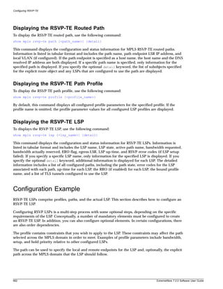
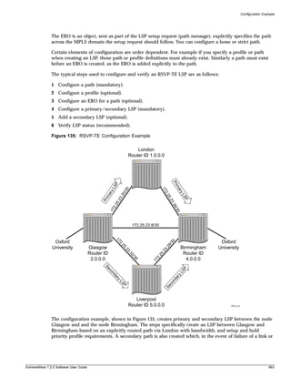
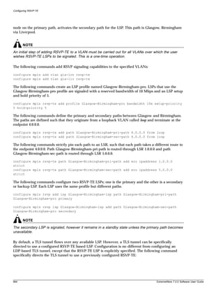


![Configuring MPLS Layer-2 VPNs
is using an LDP established LSP, provided there are parallel routed paths to the TLS tunnel endpoint,
the TLS tunnel will automatically shift from a withdrawn or failed LSP to the next best available LSP.
For tunnel LSPs established using RSVP-TE, secondary LSPs can be configured that can be hot-swapped
in the event of a primary LSP failure. Thus, even though the underlying tunnel LSP may have changed,
the Layer-2 VPN data plane remains unaffected.
TLS VPN Characteristics
Characteristics of TLS include:
• Use of LDP or RSVP-TE to establish tunnel LSPs.
• Tunnel support for dynamic TLS tunnels using Targeted LDP sessions or static TLS tunnels using
configured VC labels.
• Tunnel endpoints are identified via configured IP addresses or specified RSVP-TE LSPs.
VLAN label mappings are configured at both ends of a TLS tunnel. Support for signalling VLAN label
to VLAN ID mappings using configured VC ID and Group ID (as specified in the Martini IETF drafts)
or using the manually configured ingress and egress VLAN labels.
• All tunneled frames are in tagged Ethernet format.
• Support is provided for tunneling frames received from Ethernet ports or PoS ports running the
Bridge Control Protocol (BCP).
• VLAN IDs can be different at each end of a TLS tunnel, the VLAN ID is set by the egress switch to
match that of the locally configured VLAN.
• Support for full-mesh and hub-and-spoke VPN architectures with an integrated 256k tunnel MAC
cache.
• Support for up to 8 tunnel endpoints per VPN and up to 16k total tunnels per LER.
• Tunnel traffic can be load-shared across up to four equal cost LSPs.
Configuring MPLS Layer-2 VPNs
This section describes how to configure MPLS Layer-2 VPNs, and includes the following topics:
• Adding a TLS Tunnel on page 670
• Deleting a TLS Tunnel on page 672
• Displaying TLS Configuration Information on page 672
Adding a TLS Tunnel
To add a static labeled TLS tunnel, use the following command:
configure mpls add tls-tunnel <tunnel_name> [lsp <lsp_name> | <ipaddress>
|<host_name>] <local_vlan_name> tls-labels <ingress_label> <egress_label> {mode [core
|spoke]}
To add a dynamic labeled TLS tunnel (martini-draft compliant), use the following command:
670 ExtremeWare 7.2.0 Software User Guide](https://image.slidesharecdn.com/extremewareuserguide72-110124002726-phpapp01/85/Extreme-wareuserguide72-670-320.jpg)
![Configuring MPLS Layer-2 VPNs
configure mpls add tls-tunnel <tunnel_name> [lsp <lsp_name> | <ipaddress> |
<host_name>] <local_vlan_name> [tls-labels <ingress_label> <egress_label> | vcid
<vcid> {<groupid>} {from [<local_endpoint_ipaddress> | <local_endpoint_vlan>]}]
The <tunnel_name> parameter is a character string that is to be used to identify the TLS tunnel within
the switch. It must begin with an alphabetic character and can contain up to 31 additional alphanumeric
characters.
The <ipaddress> parameter identifies the peer LSR that is the endpoint of the tunnel. This IP address
should be configured with a 32-bit prefix on the peer LSR. When the peer LSR is also an Extreme
switch, either OSPF must also be enabled on the VLAN to which the IP address is assigned (using the
configure ospf add vlan command on the peer switch), or the peer switch must be configured to
distribute direct routes into the OSPF domain (using the enable ospf export direct command). The
ospf export command should be used when the tunnel LSP needs to cross OSPF area boundaries or
when ESRP is enabled on the VLAN to which the IP address is assigned.
The TLS tunnel peer may also be specified with the host_name parameter. If the tunnel peer LSR is
specified using this parameter, the DNS client must be configured so that the host name can first be
resolved to an IP address. TLS tunnel endpoints that begin with an alphabetic character are assumed to
be host names and DNS resolution is attempted.
The <lsp_name> parameter can be used to explicitly identify the RSVP-TE LSP path to the egress TLS
LSR. When an LSP name is specified, a targeted LDP session is established across the specified RSVP-TE
LSP. The LSP endpoint specified by the associated path is used as the endpoint for the targeted LDP
session.
The <local_vlan_name> parameter identifies the Layer-2 traffic that is to be transported. All of the
local traffic received by the switch for this VLAN is transported across the tunnel.
The tls-labels parameters specify the innermost labels of the tunnel label stack and are used to
configure static TLS label tunnels. The <egress_label> is inserted into the MPLS header of Layer-2
frames forwarded onto the tunnel LSP by this switch, and must be meaningful to the peer TLS node.
All traffic received from the tunnel LSP that contains the <ingress_label> is forwarded to the local
VLAN identified by the <local_vlan_name> parameter.
When ingress traffic is forwarded to the local VLAN, the VLAN ID is set to the VLAN ID of the local
VLAN, without regard to the VLAN ID in the MAC header of the frame received from the tunnel LSP.
Thus, there is no requirement that all sites of an extended VLAN be configured to use the same VLAN
ID. This can simplify network management in some situations.
The tls-labels parameters are specified using hexadecimal notation. The value of the ingress_label
parameter must be unique within the switch (the same <ingress_label> value cannot be used for two
different tunnels). The valid range of the ingress label parameter is [8C000..8FFFF].
The valid range of the <egress_label> parameter is [00010..FFFFF]. If the peer LSR is also an Extreme
switch, then the <egress_label> must be in the range [8C000..8FFFF].
Because LSPs are unidirectional in nature, coordinated configuration is required at both tunnel endpoint
switches. The <egress_label> at one tunnel endpoint switch must match the <ingress_label> at the
other tunnel endpoint switch, and vice versa.
The <vcid> and <groupid> parameters are used to configure dynamic TLS tunnels when full
martini-draft TLS tunnel compliance is desired. The vcid and groupid values are advertised on a
targeted LDP session to the specified tunnel endpoint IP address in a martini-draft defined FEC-TLV.
Each LER advertises the vcid, groupid, and VLAN label in the Label Mapping message across an LDP
ExtremeWare 7.2.0 Software User Guide 671](https://image.slidesharecdn.com/extremewareuserguide72-110124002726-phpapp01/85/Extreme-wareuserguide72-671-320.jpg)
![Configuring MPLS Layer-2 VPNs
session. This three-tuple TLS tunnel information allows each egress LER to dynamically bind the TLS
tunnel to a local VLAN. The vcid is a non-zero 32-bit ID that defines the tunnel connection and the
optionally specified groupid is a 32-bit value that defines logical virtual tunnel connection group. The
groupid value defaults to zero if not explicitly configured.
The optional from parameter defines the <local_endpoint_ipaddress> from which the dynamic TLS
tunnel is established. Since dynamic TLS tunnels must first establish an LDP session to the endpoint
prior to exchanging tunnel vcid parameters, the TLS endpoint switch must be capable of accepting LDP
Targeted Hello messages for the configured TLS tunnel's targeted ipaddress. By default, the
local_endpoint_ipaddress is the configured OSPF Router ID. The from parameter must be specified
when dynamic TLS tunnels are used in conjunction with ESRP. The local_endpoint_ipaddress should
be configured to match the local ESRP VLAN's interface IP address. This allows dynamic TLS tunnels to
properly fail over to the slave switch when both the master and the slave switch are configured with the
same local_endpoint_ipaddress.
Optionally, the local_endpoint_vlan may be specified in place of the local_endpoint_ipaddress.
There is no TLS tunnel functional difference between these two configuration parameters. If the
local_endpoint_vlan parameter is specified, the local endpoint IP address used for the TLS tunnel is
the IP interface address of the specified local_endpoint_vlan.
The optional mode parameter configures the broadcast and unknown packet-forwarding behavior for the
TLS tunnel. The flood mode options are core and spoke. When two or more TLS tunnels are configured
for the same TLS VLAN, each configured TLS tunnel and the local TLS VLAN are treated as separate
bridge ports within a single L2 broadcast domain. When the mode is configured as spoke, all received
flood traffic (for example, broadcast, multicast, and unknown unicast packets) is retransmitted out every
TLS tunnel and the local TLS VLAN, except for the interface that the packet was received. When the
mode is configured as core, flood traffic received from a TLS tunnel is forwarded to the local TLS VLAN
and is flooded to all spoke TLS tunnels. Flood traffic received from the local TLS VLAN is retransmitted
onto every TLS tunnel regardless of its configured mode. The default mode is core.
Deleting a TLS Tunnel
To delete one or all TLS tunnels, use the following command:
configure mpls delete tls-tunnel [<tunnel_name> | group <groupid> | all]
This command deletes the TLS tunnel with the specified tunnel name. Specify the <groupid> if you
want to delete all TLS tunnels belonging to a specific group. Use the all keyword to delete all TLS
tunnels.
Displaying TLS Configuration Information
To display TLS configuration information, use the following command:
show mpls tls-tunnel {summary | detail | <tunnel_name> {detail} | vlan <vlan_name>
{detail}}
This command displays configuration and status information for one or all TLS tunnels. The
information displayed for each tunnel includes:
• The values of all configuration parameters for the tunnel.
• The current status of the tunnel LSP.
672 ExtremeWare 7.2.0 Software User Guide](https://image.slidesharecdn.com/extremewareuserguide72-110124002726-phpapp01/85/Extreme-wareuserguide72-672-320.jpg)
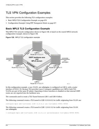
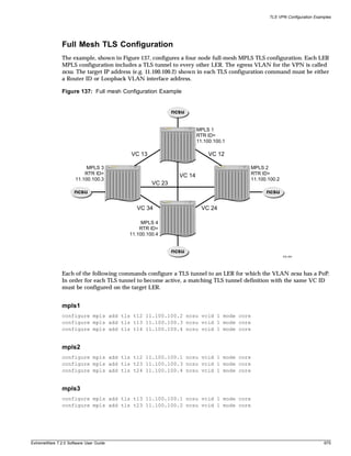
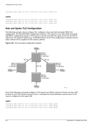
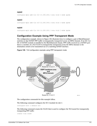
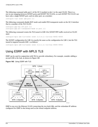
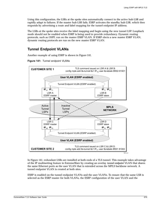
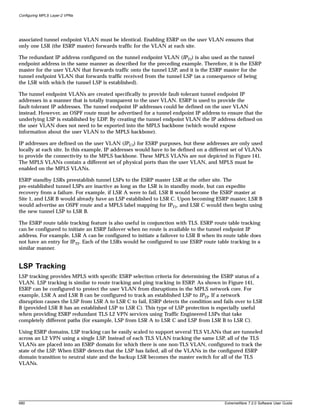
![Using ESRP with MPLS TLS
To configure LSP tracking, use the following commands:
configure vlan <vlan name> add track-lsp [<lsp_name> | ipaddress
<ipaddress>/<masklength>]
configure vlan <vlan name> delete track-lsp [<lsp_name> | ipaddress
<ipaddress>/<masklength> | all]
This command configures the LSPs tracked by ESRP in order to determine the ESRP state of the
specified VLAN. The add track-lsp command configures ESRP to track up to eight LSPs. Fail over to
the slave switch is based on the total number of established tracked LSPs. The switch with the greatest
number of established tracked LSPs is elected the master switch for the specified VLAN. Specifying the
parameter <lsp_name> instructs ESRP to track the status of an RSVP-TE LSP. Specifying the ipaddress
keyword instructs ESRP to track the LSP status for the IP prefix as defined by the
<ipaddress/masklength> parameter. Both types of LSPs can be tracked simultaneously. The delete
track-lsp command removes an LSP from ESRP tracking for the specified VLAN. If you specify the
all keyword, all configured LSPs are removed from ESRP tracking for the specified VLAN.
Configuration Example
The MPLS TLS ESRP configuration example, shown in Figure 142, illustrates how to configure a pair of
BlackDiamond switches to provide redundant Layer-2 VPN services over an MPLS domain. Two
additional switches have been added to the TLS MPLS network configuration example shown in
Figure 136, LSR 5 and LSR 6. LSR 5 and LSR 6 provide redundant connectivity for TLS VLANs into the
MPLS domain.
ExtremeWare 7.2.0 Software User Guide 681](https://image.slidesharecdn.com/extremewareuserguide72-110124002726-phpapp01/85/Extreme-wareuserguide72-681-320.jpg)
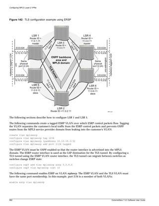
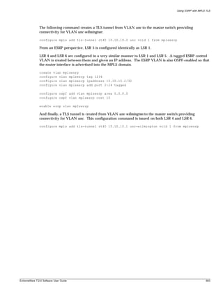


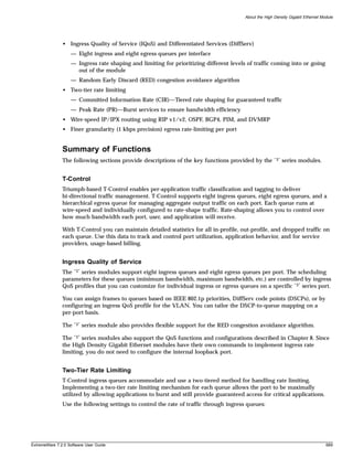
![High Density Gigabit Ethernet Module
• Committed Information Rate (CIR)
• Peak Rate (PR)
The CIR (specified in either bps or a percentage of the link speed) is the rate of traffic guaranteed to
reach the backplane (also considered high priority traffic). Depending on conditions, traffic that exceeds
the CIR may be dropped.
The PR is a rate equal to or greater than the CIR but less than or equal to the link speed that sets the
maximum burst rate that the queue can reach (also considered low priority traffic).
Configuring the High Density Gigabit Ethernet Module
This section describes the ExtremeWare commands that support the “3” series I/O modules. For
hardware installation on the Alpine 3800 series switch or the BlackDiamond 6800 series switch, see the
Extreme Networks Consolidated Hardware Guide.
NOTE
Documentation for Extreme Networks products is available on the World Wide Web at the Extreme
Networks home page at http://www.extremenetworks.com/.
Configuring Flow Control
You can configure 802.3x flow control on your “3” series module. Because these modules are
oversubscribed to the module switch fabric, traffic can congest. Flow control allows you to stop
incoming traffic when too much congestion occurs.
Flow control sends a PAUSE frame to the transmitter when traffic approaches the congestion threshold
for a specific queue. The PAUSE frame is sent before the queue overflows, so throughput is slightly
reduced when flow control is enabled. Flow control is auto-negotiated and is disabled if both ports do
not support it.
Flow control is disabled by default. To enable 802.3x flow control, use the following command:
enable flow-control ports [<portlist> | all]
To disable 802.3x flow control, use the following command:
disable flow-control ports [<portlist> | all]
Use the all keyword to specify all configured “3” series ports.
To see the flow control configuration, use the show ports configuration command. DSBL indicates
that flow control is disabled on that port. ENBL indicates that flow control is enabled while
auto-negotiation is off for that port. If flow control and auto-negotiation are both enabled, the
negotiated flow control value is displayed.
Configuring VLANs
To configure a VLAN to use a particular ingress QoS profile, use the following command:
configure vlan <vlan name> qosprofile ingress [<Ingress QOS profile> | none]
690 ExtremeWare 7.2.0 Software User Guide](https://image.slidesharecdn.com/extremewareuserguide72-110124002726-phpapp01/85/Extreme-wareuserguide72-690-320.jpg)
![Configuring the High Density Gigabit Ethernet Module
where the following is true:
• vlan name specifies a VLAN name.
• Ingress QOS profile specifies an ingress QoS profile, such as IQP1.
• none specifies that traffic from this VLAN is not associated with any ingress queue based on VLAN
ID. This is the default setting.
All VLANs are set to the default ingress QoS profile none.
Configuring Ingress QoS Functions
You can configure ingress QoS on your “3” series module. Ingress QoS is used to prioritize, rate-limit,
and rate-shape traffic received on the “3” series ports. The following sections describe the commands
used to configure ingress QoS on your “3” series module.
NOTE
Untagged packets are always dot1q VLAN tagged internally. Therefore, ingress classification based on
dot1p is always valid if there are no higher priority classifications that are valid. Configuring the ingress
qostype priority for dot1p above any other classification method will effectively disable that classification.
Untagged packets get their dot1p VLAN priority bits set to the value configured by configure vlan
<vlan> qosprofile <QoS Profile Name> and configure port <port> qosprofile <QoS
Profile Name>. The former command takes precedence over the latter.
Configuring Ingress QoS Settings
Congestion can cause ingress traffic with different dot1p priority values or different DiffServ code
points to be dropped on oversubscribed “3” series I/O modules. Ingress QoS allows received traffic
with different VLAN priority values, different DiffServ code points (IP TOS), or from different VLANs
to be classified to up to eight different ingress queues. This allows for specified traffic types to be
queued separately so they remain unaffected by congestion in other ingress queues. Default ingress QoS
settings avoid discards of higher priority traffic (identified by DiffServ code point or VLAN priority) in
the presence of ingress congestion.
DiffServ examination is enabled by default on all “3” series ports; DiffServ examination is disabled by
default on all other ports.
To configure ingress QoS, use the following command:
configure qostype ingress priority [diffserv | dot1p | vlan | application]
<qos-priority (0-15)>
where the following is true:
• diffserv specifies the ingress priority based on DiffServ information. The default is 3.
• dot1p specifies the ingress priority based on dot1p information. The default is 1.
• vlan specifies the ingress priority of VLAN ID-based input queue selection. The default is 2.
• application specifies the priority of the ingress queue selection based on application examination
rules (IP protocol number and TCP/UDP port numbers). The default is 5.
• priority range is 0-15 (15 is the highest priority). Each queue selection criteria must have a unique
priority (no ties).
ExtremeWare 7.2.0 Software User Guide 691](https://image.slidesharecdn.com/extremewareuserguide72-110124002726-phpapp01/85/Extreme-wareuserguide72-691-320.jpg)
![High Density Gigabit Ethernet Module
Ingress QoS types with a greater value take higher precedence. The queue selection criteria with the
highest priority, if enabled in the received packet, is used first, followed by the remaining criteria in
descending order.
To restore the default ingress QoS settings, use the following command:
unconfigure qostype ingress priority
To view the ingress QoS settings on your “3” series module, use the following command:
show qostype ingress priority
The following is sample output from this command:
Ingress QoS Type Priority
Application 5
Diffserv 3
Vlan 2
Dot1p 1
Configuring Application Examination Rules
Creating application examination rules configures ingress queue classification based on application QoS
(IP protocol number, TCP ports, or UDP ports). The command for creating application examination
rules is similar to the existing config diffserv examination command except that it has more
arguments and can overlap on the same ports, so an application name is used to identify each rule. The
none instead of IQoS profile means that AQoS is not used for queue classification for the matching
packets and the next lower ingress qostype priority (queue classification) is used. Precedence is
required, since a match on multiple rules is possible. Up to 1,000 application examination rules can be
created.
To create application examination rules, use the following command:
create application examination <application name> [ip-protocol <number> | [tcp-port |
udp-port] <number> match [source-only | dest-only | source-or-dest] ] [<Ingress QOS
profile> | none] precedence <(1-65000)>
where the following is true:
• application name specifies the name string to associate with this rule.
• ip-protocol specifies that a match will be attempted on the IP protocol number in the received
packets.
• tcp-port specifies that a match will be attempted on the TCP port numbers in the received packets.
• udp-port specifies that a match will be attempted on the UDP port numbers in the received packets.
• source-only specifies that when doing TCP or UDP comparisons, only source port numbers will be
compared.
• dest-only specifies that when doing TCP or UDP comparisons, only destination port numbers will
be compared.
• source-or-dest specifies that when doing TCP or UDP comparisons, both source and destination
port numbers will be compared. The match is successful if either source or destination port equals
the specified port number.
• Ingress QoS profile specifies an ingress QoS profile name to associate with any ingress packets
matching this rule.
692 ExtremeWare 7.2.0 Software User Guide](https://image.slidesharecdn.com/extremewareuserguide72-110124002726-phpapp01/85/Extreme-wareuserguide72-692-320.jpg)
![Configuring the High Density Gigabit Ethernet Module
• none specifies that traffic matching this rule will not be associated with any ingress queue based on
application examination.
• precedence specifies the precedence value for this rule. If an incoming packets matches multiple
rules, the precedence number is used to determine which rule to apply (lower number = higher
precedence).
To delete an previously configured application rule, use the following command:
delete {application examination} <application name>
Up to 60 application examination rules can be associated with each port. To add or delete an application
examination rule to or from ports on a specified “3” series module, use the following command:
configure {application examination} <application name> [add | delete] ports
[<portlist> | all]
To enable or disable application examination rules on specified ports, use the following commands:
enable application examination ports [<portlist | all]
disable application examination ports [<portlist | all]
To view the configured application examination rules on your “3” series module, use the following
command:
show {application examination} {<application name>}
The following is sample output from this command:
IP TCP/UDP
Name Typ Prt Port Match Q Prec Ports
============ === === ===== ====== ==== ====== ==================================
TCP20 tcp 6 20 dst IQP3 100 4:1, 4:2, 4:3, 4:4, 4:5, 4:6
4:7, 4:8, 4:9, 4:10, 4:11, 4:12
4:13, 4:14, 4:15, 4:16, 4:17, 4:18
4:19, 4:20, 4:21, 4:22, 4:23, 4:24
Configuring Ingress QoS Profiles
The “3” series modules support eight ingress queues. The scheduling parameters (minimum bandwidth
and maximum bandwidth) for these queues are controlled by ingress QoS profiles IQP1 through IQP8,
which means queue #0 is controlled by IQP1, queue #1 is controlled by IQP2, and so on.
Define Ingress QoS profiles with the following command:
configure qosprofile ingress <Ingress QOS profile> [minbw <percent> % maxbw <percent>
% | committed-rate <bps> [k | m] peak-rate <bps> [k | m]] red-threshold <percent> %
maxbuf <percent> % ports [<portlist> | all]
where the following is true:
• Ingress QoS profile specifies an ingress QoS profile. Ingress QoS profiles are IQP1 through IQP8.
• minbw specifies the minimum percentage of the bandwidth guaranteed to be available to the
specified queue for transmissions from the ingress QoS profile.
ExtremeWare 7.2.0 Software User Guide 693](https://image.slidesharecdn.com/extremewareuserguide72-110124002726-phpapp01/85/Extreme-wareuserguide72-693-320.jpg)
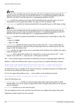
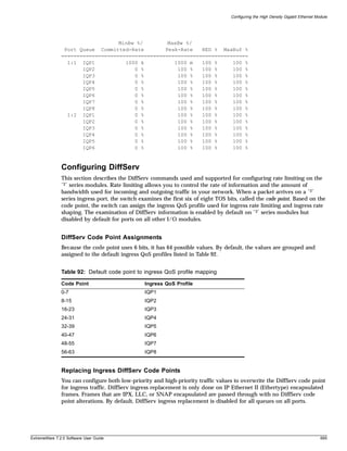
![High Density Gigabit Ethernet Module
To configure DiffServ replacement, use the following command:
configure diffserv ingress replacement low-priority code-point <number> high-priority
code-point <number> ports [<portlist> | all] {<Ingress QOS profile>}
where the following is true:
• low-priority code-point specifies the low-priority DiffServ code point (IP TOS) value to use to
overwrite low-priority ingress traffic. The default is 0. The range is 0 to 63.
• high-priority code-point specifies the high-priority DiffServ code point (IP TOS) value to use to
overwrite high-priority ingress traffic. The default is 0. The range is 0 to 63.
• portlist specifies one or more “3” series ports. If you specify the all keyword, all “3” series ports
are selected.
• Ingress QOS profile specifies an optional ingress QoS profile. If you do not specify an ingress
QoS profile, all ingress QoS profiles for the indicated ports will be affected.
To enable the replacement of ingress DiffServ code points, use the following command:
enable diffserv ingress replacement [high-priority | low-priority |
low-and-high-priority] ports [<portlist> | all] {<Ingress QOS profile>}
where the following is true:
• high-priority enables DiffServ for high-priority traffic (traffic received below the committed rate
configured for the ingress QoS profile).
• low-priority enables DiffServ for low-priority traffic (traffic received above the committed rate
configured for the ingress QoS profile).
• low-and-high-priority enables DiffServ for both low-priority and high-priority traffic.
• portlist specifies one or more “3” series ports. If you specify the all keyword, all “3” series ports
are selected.
• Ingress QOS profile specifies an optional ingress QoS profile. If you do not specify an ingress
QoS profile, all ingress QoS profiles for the indicated ports will be affected.
To verify the DiffServ configuration, use the following command:
show ports {mgmt | <portlist>} info {detail}
When you specify the detail keyword, the output displays the flow control state and the ingress QoS
profile, ingress IPTOS replacement, and egress rate limiting configurations.
To disable the replacement of Ingress DiffServ code points, use the following command:
enable diffserv ingress replacement [high-priority | low-priority |
low-and-high-priority] ports [<portlist> | all] {<Ingress QOS profile>}
Resetting Ingress DiffServ Code Points
To reset the DiffServ code point for a specified “3” series port, use the following command:
unconfigure diffserv ingress replacement ports [<portlist> | all]
696 ExtremeWare 7.2.0 Software User Guide](https://image.slidesharecdn.com/extremewareuserguide72-110124002726-phpapp01/85/Extreme-wareuserguide72-696-320.jpg)
![Configuring the High Density Gigabit Ethernet Module
Configuring Rate Limiting on Egress Ports
You can configure the amount of bandwidth available for outgoing traffic on a “3” series module. The
rate you configure is applicable to the aggregate of all outgoing traffic on a port.
NOTE
This setting is independent of any “i” series egress rate-limiting configurations that you have on the
switch and is applied to the aggregate bandwidth after the “i” series per-queue egress rate-limiting.
You can configure either the maximum percentage of bandwidth or the maximum speed allowed for
egress traffic on a selected port. To configure the maximum egress rate limit on a “3” series port, use the
following command:
configure ports <portlist> egress-rate-limit [percent <percent> | rate <bps> [k | m]]
where the following is true:
• portlist specifies one or more “3” series ports.
• percent specifies the maximum percentage of bandwidth allowed for all egress traffic for each
selected port. The range is 0 to 100. The default is 100.
• bps specifies the maximum bandwidth for all egress traffic for each selected ports in either kbps or
mbps. The range is:
— kbps: 0 to 1000000
— mbps: 0 to 1000
• k specifies kilobits per second.
• m specifies megabits per second.
To display the maximum egress rate limit on the specified “3” series ports, use the following command:
show ports {<portlist>} egress-rate-limit
The following is sample output from this command:
PORT Egress-Rate
=====================
2:1 100 %
2:2 100 %
2:3 100 %
2:4 1000 k
2:5 100 %
2:6 10 m
2:7 100 %
2:8 100 %
2:9 100 %
2:10 100 %
2:11 100 %
2:12 100 %
2:13 100 %
2:14 100 %
2:15 100 %
2:16 100 %
ExtremeWare 7.2.0 Software User Guide 697](https://image.slidesharecdn.com/extremewareuserguide72-110124002726-phpapp01/85/Extreme-wareuserguide72-697-320.jpg)
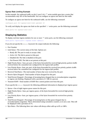
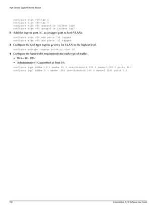
![Power Over Ethernet
For detailed information about using the PoE command set to configure and manage PoE, see the
ExtremeWare Software Command Reference Guide.
Port Power Operator Limit
Each port is configured by default to permit AF-compliant devices and to cause a fault for any device
that exceeds the power level defined for the device class. You can also use the following command to
specify a power limit on a per-port basis:
config inline-power violation-precedence [advertised-class | operator-limit |
max-class-operator | none] ports <portlist>
Power is allowed up to maximum limit (20 watts). There are several options for defining a violation
policy and creating a device fault:
• Class violation—Power is removed if the PD consumes more than the discovered class limit.
• Operator limit—Power is removed if the PD consumes more than the operator-specified limit.
• Maximum of operator limit and class—Power is removed if the PD consumes more than the operator
limit or discovered class limit, whichever is greater.
• None—Power is removed if the device exceeds the maximum limit of 20 watts.
Power Budget Management
The Alpine FM-32Pi PoE Module software is responsible for managing overall power consumption to
ensure that it does not attempt to deliver more power than is available. You can configure the way in
which the Alpine FM-32Pi PoE Module allocates power to devices upon power-up and in the event that
available power is reduced.
Reserved Power
You can reserve power for devices connected to a specific port by using the following command:
config inline-power reserved budget <milliwatts> ports <portlist>
When a new device is discovered, its defined power requirement is first subtracted from the reserved
power pool. If there is sufficient reserved power on the port, the device is powered. Otherwise the
remaining power is subtracted from the common pool, and the device is powered if there is sufficient
reserved plus common power available. Reserved power is subtracted from the common pool and
unavailable to other ports. The total reserved power cannot exceed the total available power.
NOTE
A connected device may draw more power than the amount reserved, due to configuration error or
oversight. The switch provides notification if this occurs.
Common Power Pool
The common power pool represents the total amount of power available on a per-slot basis, less any
power reserved or allocated to currently powered devices. When a new device is discovered, its defined
power requirements are subtracted from the common power pool. If the common pool does not have
702 ExtremeWare 7.2.0 Software User Guide](https://image.slidesharecdn.com/extremewareuserguide72-110124002726-phpapp01/85/Extreme-wareuserguide72-702-320.jpg)
![Port Power Management
sufficient available power, power is not supplied to the device. In this case, the port is placed in a
power-denied state. The device can be powered at a later time if more power becomes available to the
common power pool due to another device disconnecting or if previously reserved power becomes
available.
If multiple devices are in the denied state and more power becomes available, the devices are powered
in order of connection.
Port Connection Order
The Alpine FM32Pi PoE Module software tracks the order of connection for powered devices. The
connection order is recorded at the time a device is first discovered and classified. The connection order
is reset if the device is disconnected. This connection order is maintained even if the switch is powered
down or power is interrupted, and the device must be discovered again.
During system startup, ports are powered initially based only on the connection order. During normal
system operations, port power order is determined based on discovery time. The port with the earliest
discovery time is powered first.
You can view the connection history for a selected port by using the following command:
show inline-power info [port <portlist | detail port <portlist]
You can view the port connection order for a selected slot by using the following command:
show inline-power stats slot <slotlist>
You can clear the connection history for a selected slot by using the following command:
clear inline-power connection-history slot <slot_number>
Port Power Reset
You can set ports to experience a power-down, discover, power-up cycle without returning the power to
the common pool. This allows you to reset powered devices without losing their claim to the common
power pool or connection order.
The following command power cycles the specified ports:
reset inline-power ports <portlist>
Ports are immediately de-powered and re-powered, maintaining current power allocations.
Port Power Events
If a port has sufficient reserved power for a newly discovered and classified device, the device receives
power. If additional power is required and the common pool has sufficient available power, the device
is powered and the incremental power is subtracted from the common pool. If the port does not have
reserved power, but sufficient power is available from the common pool, the power is subtracted from
the pool.
Port power budget is determined based upon the maximum class power levels or operator specification,
not actual consumed power. For example, if a port is configured with an operator limit of 20 watts and
the violation precedence is set to the operator limit, then 20 watts is budgeted for the port even if a 5
ExtremeWare 7.2.0 Software User Guide 703](https://image.slidesharecdn.com/extremewareuserguide72-110124002726-phpapp01/85/Extreme-wareuserguide72-703-320.jpg)
![Power Over Ethernet
watt 802.3af compliant device is connected. The following configuration commands are used to
configure the operator limit and violation precedence:
config inline-power operator-limit <milliwatts> ports <portlist>
config inline-power violation-precedence [advertised-class | operator-limit |
max-class-operator | none] ports <portlist>
If a sufficient mix of reserved and common power is not available, the port enters a denied state and is
not given power.
Ports are powered based upon their discovery time. Ports with the oldest discovery time are powered
first.
If a device consumes more power than it is allocated by class type, it is considered a class violation. The
device enters a fault state, and unreserved power is returned to the common pool. Power is also
returned to the common pool if a port is disconnected. The device stays in the fault state until you
explicitly clear the fault, disable the port for power, or disconnect the device.
You can clear a fault by using the following command:
clear inline-power fault ports <portlist>
You can disable a port for power by using the following command:
disable inline-power [ports all | <portlist>]
Configuring Power Over Ethernet
Power Over Ethernet on the Alpine chassis supports a full set of configuration and monitoring
commands that allow you to:
• Configure and control power distribution for PoE at the system (slot) level
• Configure and control power distribution for PoE at the port level
• Detect powered devices on the line in real time
• Monitor and control fault conditions
• Configure and monitor status at the port level
• Manage an over-subscribed power budget
Use the inline power commands described in the following sections to configure PoE on Alpine FM32Pi
Module ports. For detailed information about using the PoE command set to configure and manage
PoE, see the ExtremeWare Software Command Reference Guide.
Controlling and Monitoring System and Slot Power
Use the general switch management commands described in this section to control and monitor power
at the system level and slot level. The main power supply information and settings apply to the system.
System power to the PoE controller is provided by the main PSU (Power-One PALS 400). This unit
provides power, temperature, and fan monitoring status.
704 ExtremeWare 7.2.0 Software User Guide](https://image.slidesharecdn.com/extremewareuserguide72-110124002726-phpapp01/85/Extreme-wareuserguide72-704-320.jpg)
![Power Over Ethernet
Configuring a Backup Power Source. You can optionally set up the internal power supply to
provide backup power if the external 48V power source loses power. Use the following command to
add or remove backup power:
config inline-power backup-source [internal | none] slot <slot_number>
Using the internal keyword selects the internal power supply as the backup power source. Using the
none keyword removes any backup power supply for the external 48V power source. Use the following
command to reset the backup power source to its default value for the specified slot:
unconfig inline-power backup-source slot <slot_number>
Resetting the backup power source does not take effect until the power is cycled on the slot.
Replacing the Firmware. A version of PoE firmware is built into ExtremeWare to allow easy
replacement if necessary. If the current micro controller firmware becomes corrupted, ExtremeWare logs
a message in syslog prompting for a firmware upgrade. Use the following command to download the
firmware to the selected slot:
download firmware slot <slot_number>
Clearing Port Connection History for a Slot. You can clear the port connection history for a specified
slot by using the following command:
clear inline-power connection-history slot <slot_number>
Monitoring System and Slot Power
The PoE command set lets you view inline power status for the system and selected slots. You can view
the following information:
• System power status
• Slot power status
• Slot power configuration
• Slot power statistics
Displaying System Power Status. Use the following command to view global inline power
information for the system:
show inline-power
This command provides status for the following areas:
• Nominal power available
• Operational status of the main power supply
• Condition of the backup power device
• Configured power usage threshold for the system
• Condition of the firmware
706 ExtremeWare 7.2.0 Software User Guide](https://image.slidesharecdn.com/extremewareuserguide72-110124002726-phpapp01/85/Extreme-wareuserguide72-706-320.jpg)
![Power Over Ethernet
Following is sample output from this command:
PoE firmware status: Operational
PoE firmware revision: 1.6
Connection Order: 3 15
Total ports powered: 1
Total ports waiting for power: 0
Total ports faulted: 0
Total ports disabled: 1
Controlling and Monitoring Port Power
Use the commands described in this section to control and monitor power at the port level. Before any
port can be powered, the system must be enabled for power and the slot on which the port resides must
be enabled for power. Ultimately, the port must also be enabled for power.
Configuring Port Power
The PoE command set lets you configure inline power at the system and slot levels. (See “Configuring
System and Slot Power” on page 705.) Power control is also provided on a per port basis. You can
perform the following configuration and maintenance tasks for selected ports:
• Control inline power.
• Control the power detection mechanism.
• Set the power limit.
• Set the violation precedence.
• Set the reserved power level.
• Power cycle.
• Clear fault conditions.
• Create user-defined labels.
Controlling Inline Power to Ports. You can control whether inline power is provided to selected ports
through a set of enabling and disabling commands. Use the following command to enable inline power
provided to selected ports:
enable inline-power [ports all | <portlist>]
Disabling inline power to selected ports shuts down power currently provided to those ports. Disabling
a port providing power to a powered device (PD) will immediately remove power to the PD. The
system defaults to enabling power on all 10/100 ports. Use the following command to disable inline
power to the system:
disable inline-power [ports all | <portlist>]
Controlling the Power Detection Mechanism for Selected Ports. You can control the power
detection mechanism for selected ports by using the following command:
config inline-power detection [auto | discovery-test-only] ports <portlist>
Test mode forces power discovery operations; however, power is not supplied to detected PDs.
708 ExtremeWare 7.2.0 Software User Guide](https://image.slidesharecdn.com/extremewareuserguide72-110124002726-phpapp01/85/Extreme-wareuserguide72-708-320.jpg)
![Configuring Power Over Ethernet
To reset the power detection scheme to the default, use the following command:
unconfig inline-power detection ports <portlist>
Setting the Power Limit for Selected Ports. You can set the power limit for specified ports by using
the following command:
config inline-power operator-limit <milliwatts> ports <portlist>
You can set the power limit to the default value (15400 mW minimum according to the IEEE 802.3af
specification) or you can specify wattage in the range of 3000 – 20000 mW. This command is used with
the violation precedence setting and it has no effect if either none or advertised-class is selected for
the violation precedence. (See “Setting the Violation Precedence for Selected Ports.”)
To reset the operator limit back to the default value, use the following command:
unconfig inline-power operator-limit ports <portlist>
Setting the Violation Precedence for Selected Ports. You can set the violation precedence for
selected ports by using the following command:
config inline-power violation-precedence [advertised-class | operator-limit |
max-class-operator | none] ports <portlist>
Power will be removed or denied to PDs connected to the selected ports if the PD consumes more
power than the entered limit. The default value is max-class-operator, which removes or denies
power if the PD consumes power beyond the detected class limit or the configured operator limit,
whichever is greater.
Limits associated with the available keywords are shown in the following table:
Table 93: Violation Precedence Values
Keyword Description
advertised-class Removes or denies power if an IEEE 802.3af-compliant power device (PD)
consumes power beyond its advertised class limit.
operator-limit Removes or denies power if the PD consumes power beyond the configured
operator limit.
max-class-operator Removes or denies power if the PD consumes power beyond the detected
class limit or the operator limit, whichever is greater. Max-class-operator is the
default value.
none Removes or denies power if the PD exceeds the maximum limit of 20 watts.
The operator limit is configured with the following command:
unconfig inline-power operator-limit ports <portlist>
To reset the violation precedence to the default value, use the following command:
unconfig inline-power violation-precedence ports <portlist>
Setting the Reserved Power Level for Selected Ports. You can set the reserved power for selected
ports by using the following command:
config inline-power reserved budget <milliwatts> ports <portlist>
ExtremeWare 7.2.0 Software User Guide 709](https://image.slidesharecdn.com/extremewareuserguide72-110124002726-phpapp01/85/Extreme-wareuserguide72-709-320.jpg)
![Configuring Power Over Ethernet
— Auto: The port will power up if there is enough available power.
— Test: The port will not power up. Indicates a test mode to determine whether the port can be
discovered.
• Rsvd Pwr—Displays the amount of configured reserved power in watts.
• Oper Lmt—Displays the configured operator limit in watts. The operator limit is used only with
violation precedence.
• Viol Prec—Displays the violation precedence settings:
— ADVERTISED-LIMIT: Removes or denies power if an IEEE 802.3af-compliant powered device
(PD) consumes power beyond its advertised class limit.
— OPERATOR-LIMIT: Removes or denies power if the PD consumes power beyond the configured
operator limit.
— MAX-CLASS-OPERATOR: Removes or denies power if the PD consumes power beyond the
maximum of the detected class limit or the operator limit.
— NONE: Removes or denies power if the PD consumes power in excess of the regulatory
maximum allowable wattage.
• Label—Displays a text string, up to 13 characters in length, associated with the port.
Following is sample output from this command:
Port Config Detect Rsvd Pwr Oper Lmt Viol Prec Label
1:1 enabled auto 0.0 15.4 max-class-operator
1:2 enabled auto 10.0 15.4 advertised-limit test_port2
1:3 enabled auto 0.0 15.4 max-class-operator
1:4 enabled auto 0.0 15.4 max-class-operator
1:5 enabled auto 0.0 15.4 max-class-operator
1:6 enabled auto 0.0 15.4 max-class-operator test_port6
1:7 enabled auto 0.0 15.4 max-class-operator
Displaying Port Power Information. Use the following command to view inline power information
for the specified ports:
show inline-power info [port <portlist | detail port <portlist]
You can use this command to generate a summary report or a detailed report.
Summary output displays the following inline power information for the specified ports:
• State—Displays the port power state:
— Disabled
— Searching
— Discovered
— Delivering
— Faulted
— Disconnected
— Other
— Denied
• Class—Displays the class type:
ExtremeWare 7.2.0 Software User Guide 711](https://image.slidesharecdn.com/extremewareuserguide72-110124002726-phpapp01/85/Extreme-wareuserguide72-711-320.jpg)

![A Software Upgrade and Boot Options
This appendix describes the following topics:
• Downloading a New Image on page 717
• Saving Configuration Changes on page 721
• Using TFTP to Download the Configuration on page 723
• Synchronizing MSMs on page 724
• Upgrading and Accessing BootROM on page 724
Downloading a New Image
The image file contains the executable code that runs on the switch. It comes preinstalled from the
factory. As new versions of the image are released, you should upgrade the software running on your
system.
The image is upgraded by using a download procedure from either a Trivial File Transfer Protocol
(TFTP) server on the network or from a PC connected to the serial port using the XMODEM protocol.
Downloading a new image involves the following steps:
• Load the new image onto a TFTP server on your network (if you will be using TFTP).
• Load the new image onto a PC (if you will be using XMODEM).
• Download the new image to the switch using the following command:
download image [<hostname> | <ipaddress>] [<filename> | all-images
<filename_prefix> {image-type [non-ssh | ssh]}] {primary | secondary} {slot
<slot>}
where the following is true:
hostname—Is the hostname of the TFTP server. (You must enable DNS to use this option.)
ipaddress—Is the IP address of the TFTP server.
filename—Is the filename of the new image.
primary—Indicates the primary image.
secondary—Indicates the secondary image.
ExtremeWare 7.2.0 Software User Guide 717](https://image.slidesharecdn.com/extremewareuserguide72-110124002726-phpapp01/85/Extreme-wareuserguide72-717-320.jpg)
![Software Upgrade and Boot Options
Selecting a Primary or a Secondary Image
The switch can store up to two images: a primary and a secondary. When you download a new image,
you must select into which image space (primary or secondary) the new image should be placed. If not
indicated, the next selected boot-up image space is used. This is the primary image space by default,
but it can be changed with the following command:
use image [primary | secondary] {slot <slot>}
If two MSMs are installed in the BlackDiamond switch, the downloaded image is saved to the same
location on each one.
You can select which image the switch will load on the next reboot by using the use image command:
Downloading Images to Slots and Modules
To download an image to an individual slot on an Alpine switch, use the following command:
download image [<hostname> | <ipaddress>] [<filename> | all-images <filename_prefix>
{image-type [non-ssh | ssh]}] {primary | secondary} {slot <slot>}
If you have modules that run a software image in the Alpine or BlackDiamond chassis, and you want to
download an image to all installed modules, use the following command:
download image [<hostname> | <ipaddress>] [<filename> | all-images <filename_prefix>
{image-type [non-ssh | ssh]}] {primary | secondary} {slot <slot>}
• Use the all-images <filename_prefix> parameter to download the operational images for all
installed modules.
— filename_prefix—Specifies the filename prefix (the filename without the image extension) of
the new image.
— All of the operational images files must be located in the same directory on the TFTP server and
they must have the same filename prefix.
• Enter the filename prefix, not the filename, to successfully download the software.
— For example, if you enter v700b68.xtr, the command fails because the file extension (.xtr) is
included, and v700b68.xtr.xtr is not found.
— If you enter v700b68, without the file extension, the command executes.
• By default, if the ExtremeWare version currently running contains security features that are subject to
export restrictions (for example, SSH2), the image downloaded contains the security features.
To download an image type different from the type currently running, specify the optional
image-type keyword followed by either non-ssh or ssh.
— non-ssh—Specifies an ExtremeWare image without export-restricted security features
— ssh—Specifies an ExtremeWare image containing export-restricted security features
• The main ExtremeWare image always downloads first.
The download image process proceeds with each slot starting at slot 1.
— If the main ExtremeWare image cannot be found, the download image process is discontinued.
— If a specific image file is not found for a specific module, an error is displayed and the download
process continues to the next module.
• Slots with modules that do not support separate operational images (for example, the G8Xi or the
GM-4Ti module) are skipped.
718 ExtremeWare 7.2.0 Software User Guide](https://image.slidesharecdn.com/extremewareuserguide72-110124002726-phpapp01/85/Extreme-wareuserguide72-718-320.jpg)
![Downloading a New Image
Table 94 lists the supported modules and operational images:
Table 94: Supported modules and operational images
Module Name Image Extension Image Description
MSM, SMMi xtr ExtremeWare image
MSM Gxtr 6816 ExtremeWare image
MSM, SMMi Sxtr SSH ExtremeWare image
MSM SGxtr SSH 6816 ExtremeWare image
ARM arm ARM image
A3cSi atm3 ATM OC-3 image
P3cSi, P3cMi oc3 PoS OC-3 image
P12cSi, P12cMi oc12 PoS OC-12 image
MPLS mpls MPLS image
WM-4E1i e1 E1 WAN image
WM-4T1i t1 T1 WAN image
WM-1T3i t3 T3 WAN image
Understanding the Image Version String
The image version string contains build information for each version of ExtremeWare. You can use
either the show version or show switch command to display the ExtremeWare version running on
your switch.
Depending on the CLI command, the output is structured as follows:
• show version
Version <major>.<sub_major>.<minor> (Build<build>) {[branch | beta | tech |
patch]{<image_version>}.<image_description>-r<branch_revision>}
• show switch
<major>.<sub_major>.<minor>b<build>{[branch | beta | tech |
patch]{<image_version>}.<image_description>-r<branch_revision>}
Table 95 describes the image version fields.
Table 95: Image version fields
Field Description
major Specifies the ExtremeWare Major version number.
sub_major Specifies the ExtremeWare Sub-major version number.
minor Specifies the ExtremeWare Minor version number.
build Specifies the ExtremeWare build number. This value is reset to zero for each new Major and
Minor release.
image_version Identifies the Technology Release or Beta image version.
The image version number is zero for all but Technology Releases and Beta releases.
ExtremeWare 7.2.0 Software User Guide 719](https://image.slidesharecdn.com/extremewareuserguide72-110124002726-phpapp01/85/Extreme-wareuserguide72-719-320.jpg)
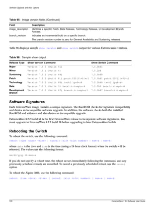
![Software Upgrade and Boot Options
use configuration [primary | secondary] [slot <slot_number> | all]
The configuration takes effect on the next reboot.
NOTE
If the switch is rebooted while in the middle of a configuration save, the switch boots to factory default
settings. The configuration that is not in the process of being saved is unaffected.
Returning to Factory Defaults
To return the switch configuration to factory defaults, use the following command:
unconfigure switch
This command resets the entire configuration, with the exception of user accounts and passwords that
have been configured, and the date and time.
To erase the currently selected configuration image and reset all switch parameters, use the following
command:
unconfigure switch all
Using TFTP to Upload the Configuration
You can upload the current configuration to a TFTP server on your network. The uploaded ASCII file
retains the command-line interface (CLI) format. This allows you to:
• Modify the configuration using a text editor, and later download a copy of the file to the same
switch, or to one or more different switches.
• Send a copy of the configuration file to the Extreme Networks Technical Support department for
problem-solving purposes.
• Automatically upload the configuration file every day, so that the TFTP server can archive the
configuration on a daily basis. Because the filename is not changed, the configured file stored in the
TFTP server is overwritten every day.
To upload the configuration, use the following command:
upload configuration [<ip address> | <hostname>] <filename> {every <time>}
where the following is true:
• ipaddress—Is the IP address of the TFTP server.
• hostname—Is the hostname of the TFTP server. (You must enable DNS to use this option.)
• filename—Is the name of the ASCII file. The filename can be up to 255 characters long, and cannot
include any spaces, commas, quotation marks, or special characters.
• every <time>—Specifies the time of day you want the configuration automatically uploaded on a
daily basis. If not specified, the current configuration is immediately uploaded to the TFTP server.
To cancel a previously scheduled configuration upload, use the following command:
upload configuration cancel
722 ExtremeWare 7.2.0 Software User Guide](https://image.slidesharecdn.com/extremewareuserguide72-110124002726-phpapp01/85/Extreme-wareuserguide72-722-320.jpg)
![Using TFTP to Download the Configuration
Using TFTP to Download the Configuration
You can download ASCII files that contain CLI commands to the switch to modify the switch
configuration. Three types of configuration scenarios that can be downloaded:
• Complete configuration
• Incremental configuration
• Scheduled incremental configuration
Configurations created in a chassis are not supported in a different model chassis. For example, a
configuration from a BlackDiamond 6808 is not supported in a BlackDiamond 6804. Configurations for
different models generate error messages for any line in the configuration that concerns unavailable
slots.
If you load a configuration from a different model, you can safely write the correct configuration over
the unsupported configuration.
Downloading a Complete Configuration
Downloading a complete configuration replicates or restores the entire configuration to the switch. You
typically use this type of download in conjunction with the upload configuration command, which
generates a complete switch configuration in an ASCII format. As part of the complete configuration
download, the switch is automatically rebooted.
To download a complete configuration, use the download configuration command using the
following syntax:
download configuration [<ip address> | <hostname>] <filename>
After the ASCII configuration is downloaded by way of TFTP, you are prompted to reboot the switch.
The downloaded configuration file is stored in current switch memory during the rebooting process,
and is not retained if the switch has a power failure.
When the switch completes booting, it treats the downloaded configuration file as a script of CLI
commands, and automatically executes the commands. If your CLI connection is through a Telnet
connection (and not the console port), your connection is terminated when the switch reboots, but the
command executes normally.
Downloading an Incremental Configuration
A partial or incremental change to the switch configuration may be accomplished by downloaded
ASCII files that contain CLI commands. These commands are interpreted as a script of CLI commands,
and take effect at the time of the download, without requiring a reboot of the switch.
To download an incremental configuration, use the following command:
download configuration [<ip address> | <hostname>] <filename> {incremental}
Do not download an incremental configuration when you have time-critical applications running. When
you download an incremental configuration, the switch immediately processes the changes, which can
affect the processing of other tasks. We recommend that you either download small incremental
configurations, or schedule downloads during maintenance windows.
ExtremeWare 7.2.0 Software User Guide 723](https://image.slidesharecdn.com/extremewareuserguide72-110124002726-phpapp01/85/Extreme-wareuserguide72-723-320.jpg)
![Software Upgrade and Boot Options
Scheduled Incremental Configuration Download
You can schedule the switch to download a partial or incremental configuration on a regular basis. You
could use this feature to update the configuration of the switch regularly from a centrally administered
TFTP server. As part of the scheduled incremental download, you can optionally configure a backup
TFTP server.
To configure the primary and/or secondary TFTP server and filename, use the following command:
configure download server [primary | secondary] [<ip address> | <hostname>] <filename>
To enable scheduled incremental downloads, use the following command:
download configuration every <time>
To display scheduled download information, use the following command:
show switch
To cancel scheduled incremental downloads, use the following command:
download configuration cancel
Remember to Save
Regardless of which download option is used, configurations are downloaded into switch runtime
memory, only. The configuration is saved only when the save command is issued, or if the
configuration file, itself, contains the save command.
If the configuration currently running in the switch does not match the configuration that the switch
used when it originally booted, an asterisk (*) appears before the command line prompt when using the
CLI.
Synchronizing MSMs
On the BlackDiamond switch, you can take the master MSM configurations and images and replicate
them on the slave MSM using the following command:
synchronize
In addition to replicating the configuration settings and images, this command also replicates which
configuration or image the MSM should use on subsequent reboots. This command does not replicate
the run-time configuration. You must use the save configuration command to store the run-time
configuration first.
Upgrading and Accessing BootROM
The BootROM of the switch initializes certain important switch variables during the boot process. If
necessary, BootROM can be upgraded, after the switch has booted, using TFTP. In the event the switch
does not boot properly, some boot option functions can be accessed through a special BootROM menu.
724 ExtremeWare 7.2.0 Software User Guide](https://image.slidesharecdn.com/extremewareuserguide72-110124002726-phpapp01/85/Extreme-wareuserguide72-724-320.jpg)
![Upgrading and Accessing BootROM
Upgrading BootROM
Upgrading BootROM is done using TFTP (from the CLI), after the switch has booted. Upgrade the
BootROM only when asked to do so by an Extreme Networks technical representative. To upgrade the
BootROM, use the following command:
download bootrom [<ip address> | <hostname>] <filename> {slot <slot>}
Accessing the BootROM Menu
Interaction with the BootROM menu is only required under special circumstances, and should be done
only under the direction of Extreme Networks Customer Support. The necessity of using these functions
implies a non-standard problem which requires the assistance of Extreme Networks Customer Support.
To access the BootROM menu, follow these steps:
1 Attach a serial cable to the console port of the switch.
2 Attach the other end of the serial cable to a properly configured terminal or terminal emulator,
power cycle the switch while depressing the spacebar on the keyboard of the terminal.
As soon as you see the BootROM-> prompt, release the spacebar. You can see a simple help menu by
pressing h . Options in the menu include
— Selecting the image to boot from
— Booting to factory default configuration
— Performing a serial download of an image
For example, to change the image that the switch boots from in flash memory, press 1 for the image
stored in primary or 2 for the image stored in secondary. Then, press the f key to boot from newly
selected on-board flash memory.
To boot to factory default configuration, press the d key for default and the f key to boot from the
configured on-board flash.
To perform a serial download, you can optionally change the baud rate to 38.4K using the b command,
and then press the s key to prepare the switch for an image to be sent from your terminal using the
XMODEM protocol. After this has completed, select the g command, to boot the image that is currently
in RAM. The switch restores the console port to 9600 bps, and begins the boot process.
NOTE
Doing a serial download does not store an image into flash, it only allows the switch to boot an
operational image so that a normal TFTP upgrade from the CLI can then be performed.
ExtremeWare 7.2.0 Software User Guide 725](https://image.slidesharecdn.com/extremewareuserguide72-110124002726-phpapp01/85/Extreme-wareuserguide72-725-320.jpg)

![Troubleshooting
Status LED on the I/O module turns amber:
Check the syslog message for a related I/O module error. If the error is an inserted an I/O module that
conflicts with the software configuration, use one of the following commands to reset the slot
configuration:
clear slot
configure slot <slot> module <module name>
Otherwise, contact Extreme Networks for further assistance.
ENV LED on the MSM turns amber:
Check each of the power supplies and all of the fans. Additionally, the status of these is indicated in the
show switch display. Look for the “Temperature” and “Power Supply” entries in the display.
Switch does not power up:
All products manufactured by Extreme Networks use digital power supplies with surge protection. In
the event of a power surge, the protection circuits shut down the power supply. To reset, unplug the
switch for 1 minute, plug it back in, and attempt to power up the switch.
If this does not work, try using a different power source (different power strip/outlet) and power cord.
Using the Command-Line Interface
The initial welcome prompt does not display:
Check that your terminal or terminal emulator is correctly configured.
For console port access, you may need to press [Return] several times before the welcome prompt
appears.
Check the settings on your terminal or terminal emulator. The settings are 9600 baud, 8 data bits, 1 stop
bit, no parity, XON/OFF flow control enabled.
The SNMP Network Manager cannot access the device:
Check that the device IP address, subnet mask, and default router are correctly configured, and that the
device has been reset.
Check that the device IP address is correctly recorded by the SNMP Network Manager (refer to the user
documentation for the Network Manager).
Check that the community strings configured for the system and Network Manager are the same.
Check that the SNMPv3 USM, Auth, and VACM configured fore the system and Network Manager are
the same.
Check that SNMP access was not disabled for the system.
728 ExtremeWare 7.2.0 Software User Guide](https://image.slidesharecdn.com/extremewareuserguide72-110124002726-phpapp01/85/Extreme-wareuserguide72-728-320.jpg)
![System Health Check
System Health Check
The system health check tests both the backplane and the CPU by periodically forwarding packets and
checking for the validity of these packets. All error messages are logged in the syslog and the
diagnostics CLI show output. A “CRIT” message will be posted to the log if any of the packet tests fail.
If you observe a failure, please contact Extreme Technical Support.
To enable system health check, use the following command:
enable sys-health-check
System health check is enabled by default.
To disable the system health checker, use the following command:
disable sys-health-check
To configure the system health checker, use the following command:
configure sys-health-check alarm-level [log | system-down | traps | default |
auto-recovery <number of tries> [online | offline]]
This command allows you to configure the switch’s reaction to a failed health check, and provides the
following options:
• log—posts a CRIT message to the log
• traps—posts a CRIT message to the log and sends a trap
• card-down—posts a CRIT message to the log, sends a trap, and brings the module down
• system-down—posts a CRIT message to the log, sends a trap, and brings the system down
The default option is log.
To view the status of the system health checker, use this command:
show diagnostics
System Memory Dump
You can download the entire contents of memory through the Ethernet management port. This is used
only for troubleshooting, and should not be used without assistance from Extreme Networks technical
support.
To transfer the dump, use the following command:
upload system-dump [<ip address>]
If you do not specify an IP address, the configured system-dump server IP address is used.
To specify the IP address to which to transfer a dump if the system-dump option is specified in the
configuration, use the following command:
configure system-dump server <ip address>
This address is also used if no address is provided in the upload system-dump command. The default
is 0 or “no IP”.
ExtremeWare 7.2.0 Software User Guide 733](https://image.slidesharecdn.com/extremewareuserguide72-110124002726-phpapp01/85/Extreme-wareuserguide72-733-320.jpg)
![Troubleshooting
To set an optional timeout for the dump transfer, use the following command:
configure system-dump timeout <seconds>
The default is 0. The minimum non-zero value is 120 seconds. The minimum recommended value is 480
seconds.
To return the system-dump configuration to the defaults, use the following command:
unconfigure system-dump
To display the system-dump server IP and dump-timeout, use the following command:
show system-dump
To specify a memory dump if a task generates a software exception, use the following command:
configure sys-recovery-level [none | [all | critical] [msm-failover | reboot |
shutdown | system-dump [maintenance-mode | msm-failover | reboot | shutdown]]]
The four options specify the action taken when the dump transfer is complete. The actions occur
whether or not the dump was successful. The maintenance-mode option leaves the switch in whatever
state it was in before the dump.
System Odometer
Each field replaceable component contains a system odometer counter in EEPROM. You can use the
show switch command to see how long an individual component has been in service since it was
manufactured. The odometer is supported on the following components:
Alpine
• SMMi
• Baseboard
• All modules
• PSU
BlackDiamond
• Master MSM and slave MSM
• Backplane
• All modules
Summit7i
• CPU
• Baseboard
• I/O boards
Summit48i
• CPU
734 ExtremeWare 7.2.0 Software User Guide](https://image.slidesharecdn.com/extremewareuserguide72-110124002726-phpapp01/85/Extreme-wareuserguide72-734-320.jpg)

![Troubleshooting
Manual Mode
Manual mode is initiated by the following command:
run diagnostics packet-memory
NOTE
This command is available on ExtremeWare 6.2.1 for BlackDiamond I/O modules, and ExtremeWare
6.2.2 and higher for BlackDiamond MSM, Alpine, and stackables. The command is only executed on
one module at a time, although you can queue up two run diagnostics commands at a time.
Automatic Mode (Auto Scan)
Automatic mode for initiating memory scanning is set up after the auto-recovery option is enabled
under the system health check configuration. This is done using the following commands:
For stackable and Alpine switches:
configure sys-health-check alarm-level [log | system-down | traps | default |
auto-recovery <number of tries> [online | offline]]
For BlackDiamond switches:
configure sys-health-check alarm-level [log | system-down | traps | default |
auto-recovery <number of tries> [online | offline]]
Automatic mode status is listed in the show switch output sys-health-check field.
Once auto-recovery mode is enabled, an automated background polling task checks every 20 seconds to
see if any checksums have occurred. Three consecutive samples must be corrupted for any module to
invoke autoscan. If autoscan is invoked, regardless of platform type or number of errors, there is an
initial period where the device is taken offline so the scan can be run.
Memory Scanning and Memory Mapping Functions
Once initiated (either automatically or by manual control) the memory scanning feature takes the
selected module offline, and initiates a thorough memory write-read operation to detect any permanent
single bit errors within the module's memory. This takes approximately 90 seconds and the module
remains offline for the duration of the scan.
Memory scanning and memory mapping behavior differs based on the platform, the mode you
configure (online or offline), and whether you configure auto-recovery or run the diagnostics manually.
736 ExtremeWare 7.2.0 Software User Guide](https://image.slidesharecdn.com/extremewareuserguide72-110124002726-phpapp01/85/Extreme-wareuserguide72-736-320.jpg)