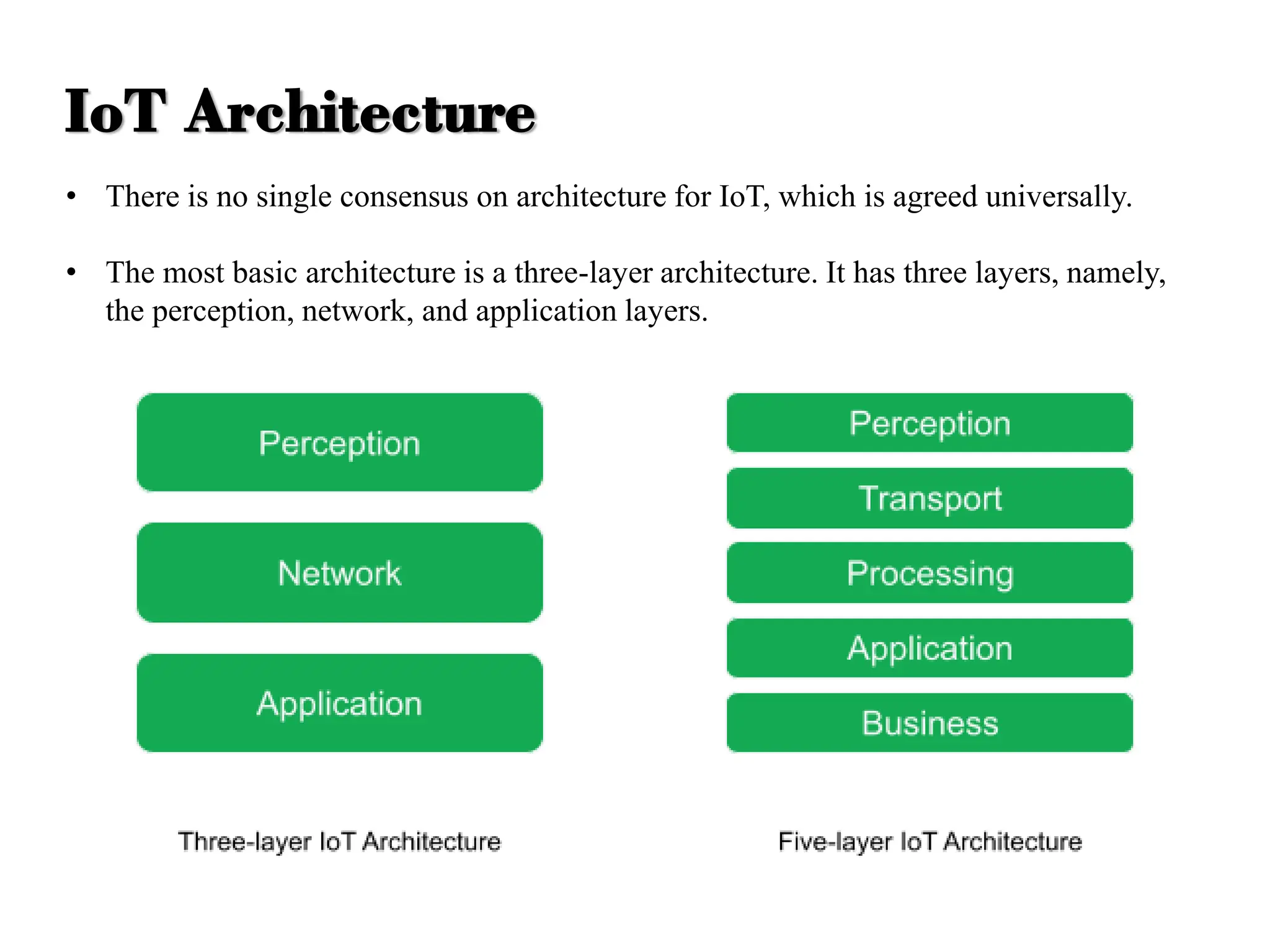
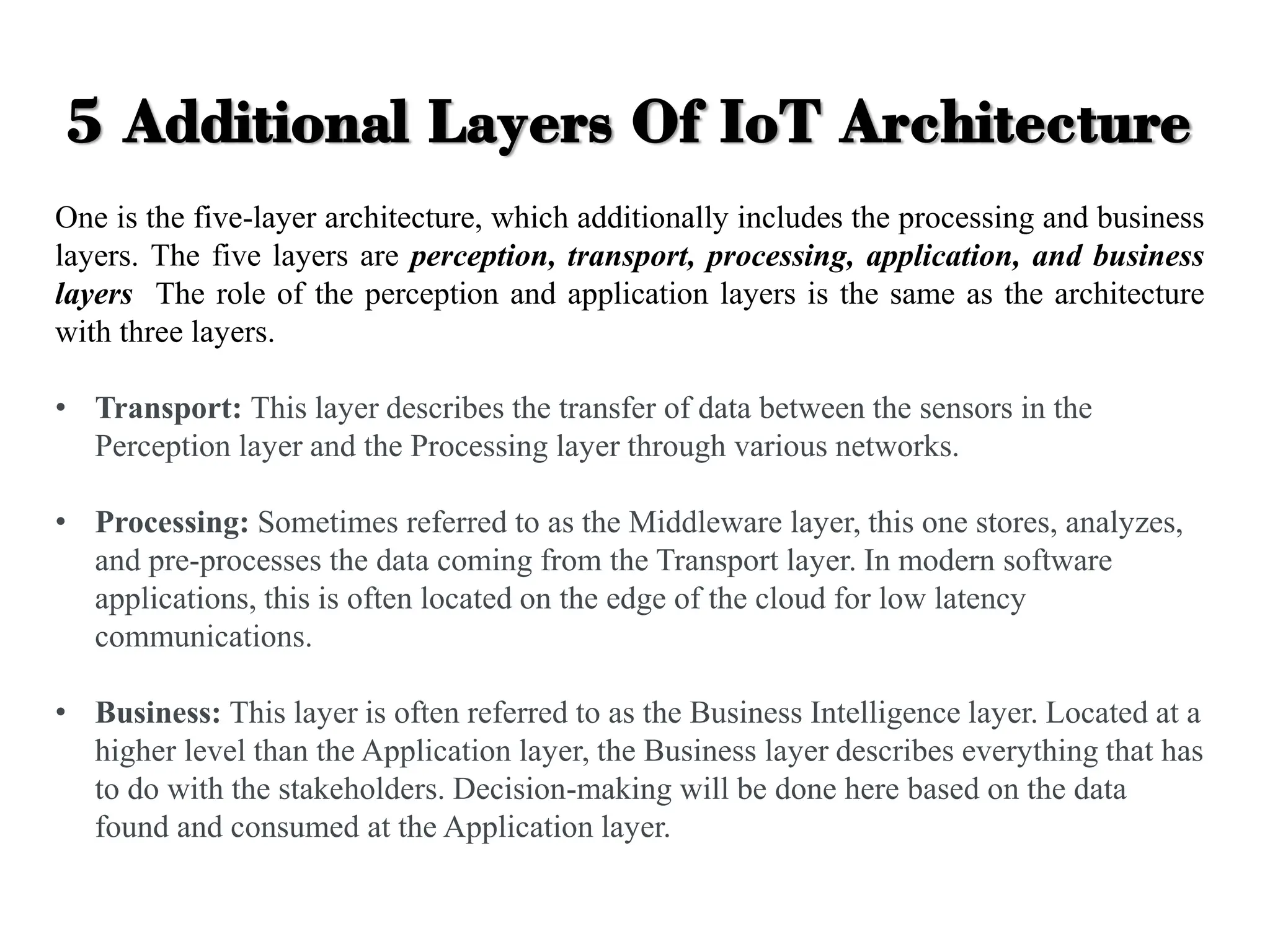
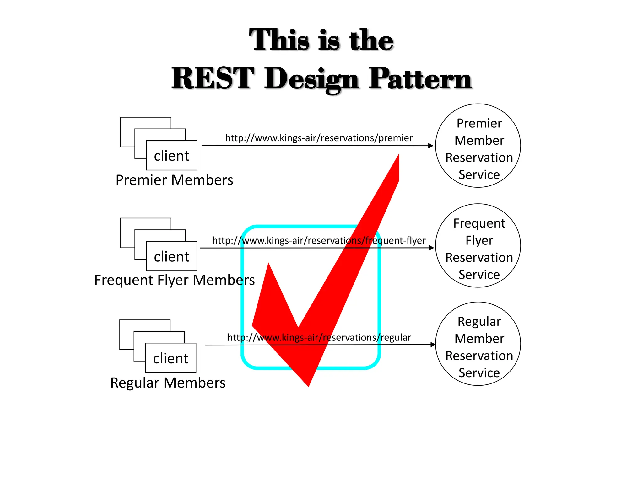
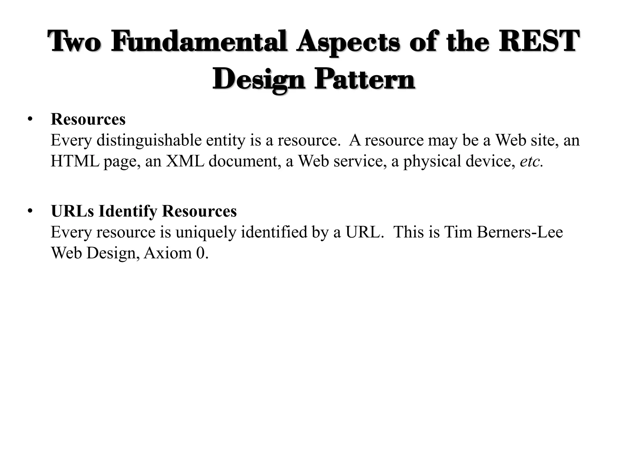
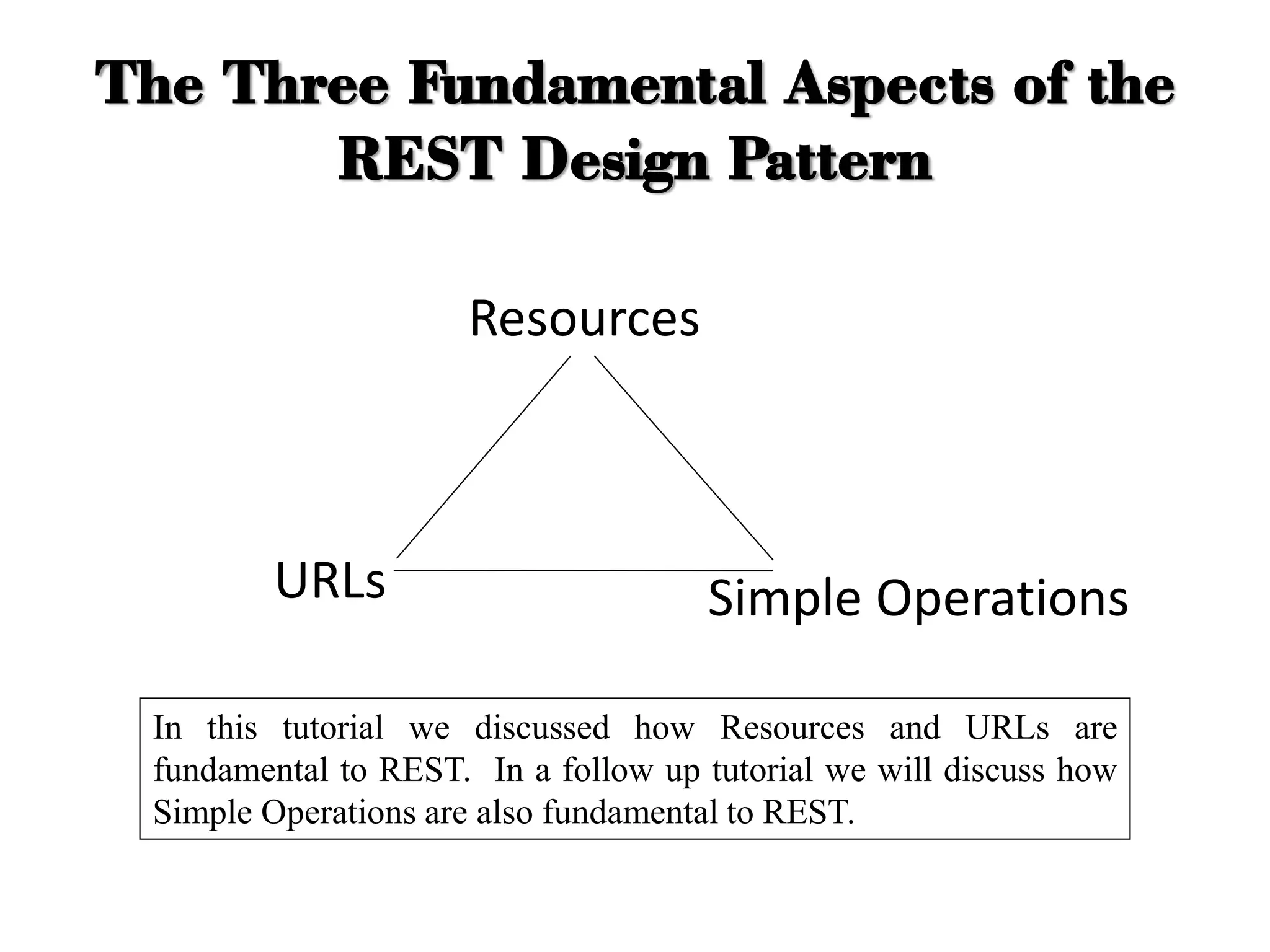
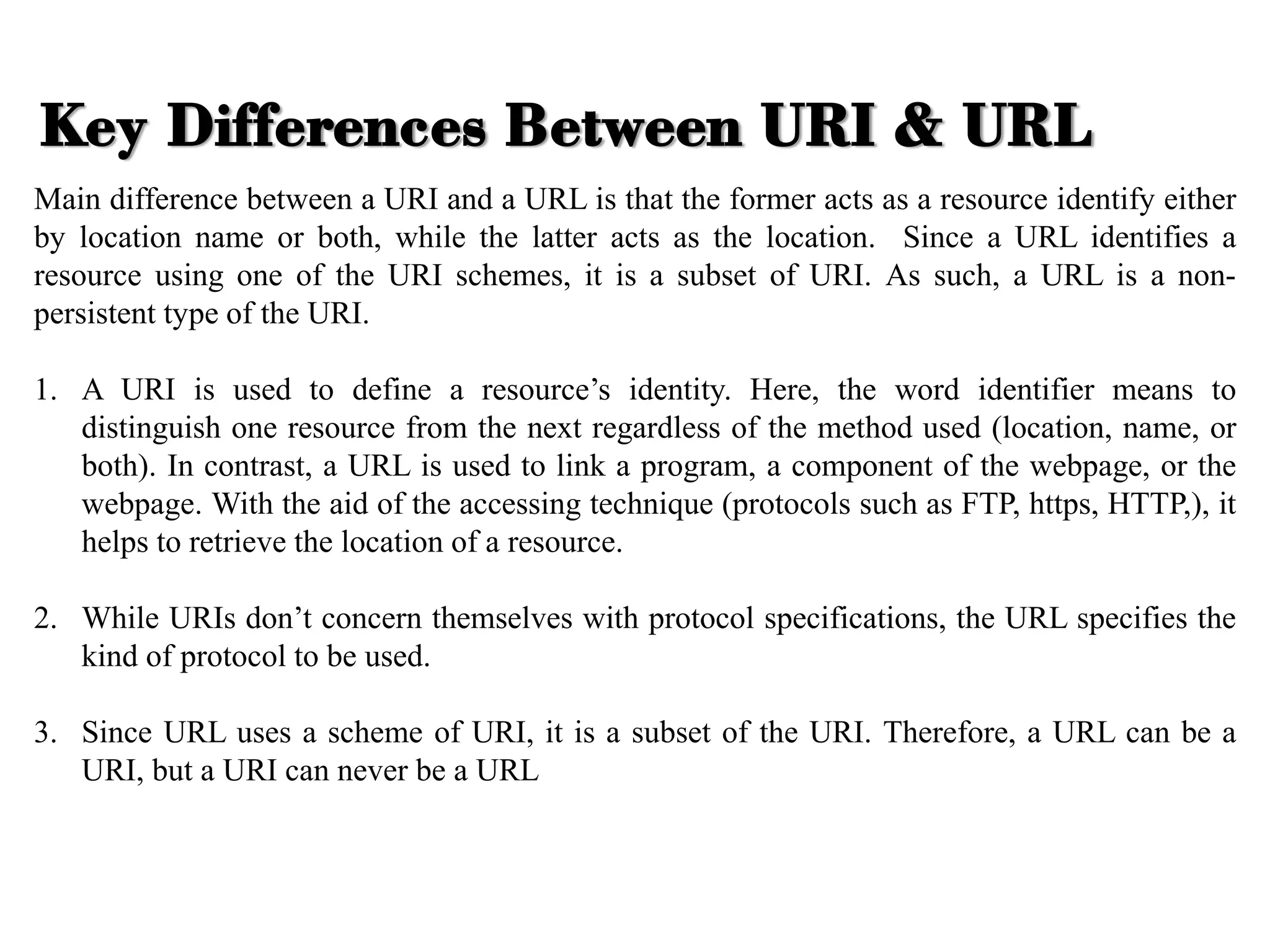
Internet Of Things
(7CS4-01)
Unit-3. Architecture & Reference Model
Department of Computer Science & Engineering
(Rajasthan Technical University, KOTA)
IoT Architecture
• There is no single consensus on architecture for IoT, which is agreed universally.
• The most basic architecture is a three-layer architecture. It has three layers, namely,
the perception, network, and application layers.
IoT Architecture
3 Major Layers Of IoT Architecture
The three-layer architecture has been the dominant model for IoT applications. The
three layers are Perception (or Devices), Network, and Application.
• Perception: The sensors themselves are on this layer. This is where the data comes
from. The data could be gathered from any number of sensors on the connected
device. Actuators, which act on their environment, are also at this layer of the
architecture.
• Network: The network layer describes how large amounts of data are moving
throughout the application. This layer connects the various devices and sends the
data to the appropriate back-end services.
• Application: The application layer is what the users see. This could be an
application to control a device in a smart-home ecosystem, or a dashboard showing
the status of the devices which are part of a system.
5 Additional Layers Of IoT Architecture
One is the five-layer architecture, which additionally includes the processing and business
layers. The five layers are perception, transport, processing, application, and business
layers The role of the perception and application layers is the same as the architecture
with three layers.
• Transport: This layer describes the transfer of data between the sensors in the
Perception layer and the Processing layer through various networks.
• Processing: Sometimes referred to as the Middleware layer, this one stores, analyzes,
and pre-processes the data coming from the Transport layer. In modern software
applications, this is often located on the edge of the cloud for low latency
communications.
• Business: This layer is often referred to as the Business Intelligence layer. Located at a
higher level than the Application layer, the Business layer describes everything that has
to do with the stakeholders. Decision-making will be done here based on the data
found and consumed at the Application layer.
4 Main Stages Of IoT Architecture
Another way to describe an IoT solution architecture is using a four-stage approach.
This architecture describes the various building blocks that constitute the IoT
solution. In this scenario, more emphasis is put on edge computing than the other
proposed designs.
• Devices: This stage is about the actual devices in the IoT solutions. These
devices could be sensors or actuators in the Perception layer. Those devices will
generate data (in the case of sensors) or act on their environment (in the case of
actuators). The data produced is converted in a digital form and transmitted to
the internet gateway stage. Unless a critical decision must be made, the data is
typically sent in a raw state to the next stage due to the limited resources of the
devices themselves.
• Internet gateways: The internet gateway stage will receive the raw data from the
devices and pre-process it before sending it to the cloud. This internet gateway could
be physically attached to the device or a stand-alone device that could communicate
with sensors over low power networks and relay the data to the internet.
• Edge or fog computing: In order to process data as quickly as possible, you might
want to send your data to the edge of the cloud. This will let you analyze the data
quickly and identify if something requires immediate attention. This layer typically
would only be concerned with recent data that is required for time-critical operations.
Some pre-processing might be done at this stage, too, to limit the data that is
ultimately transferred to the cloud.
• Cloud or data center: In this final stage, the data is stored for later processing. The
application and business layers live in this stage, where dashboards or management
software can be fed through the data stored in the cloud. Deep analysis or resource-
intensive operations such as machine learning training will happen at this stage.
IoT Reference
Model
• The IoT Reference Model
aims at establishing a
common grounding and a
common language for IoT
architectures and IoT
systems.
• It consists of the sub-models
shown in following Fig.
The yellow arrows show
how concepts and aspects of
one model are used as the
basis for another.
IoT Reference Model
IoT RM - Domain Model
o Foundation of the IoT Reference Model is the IoT Domain Model, which
introduces the main concepts of the Internet of Things like Devices, IoT Services
and Virtual Entities (VE), and it also introduces relations between these concepts.
o The abstraction level of the IoT Domain Model has been chosen in such a way that
its concepts are independent of specific technologies and use-cases.
o Based on the IoT Domain Model, the IoT Information Model has been developed.
o Defines the structure (e.g. relations, attributes) of IoT related information in an IoT
system on a conceptual level without discussing how it would be represented.
o The information pertaining to those concepts of the IoT Domain Model is
modeled, which is explicitly gathered, stored and processed in an IoT system.
The Entities, objects & Concepts in the domain model include:
1. Physical Entity
2. Virtual Entity
3. Device
4. Resource
5. Service
Domain Model
1. Physical Entity: The IoT System provides information about the physical
entity (using Sensor) or perform actuation upon the physical entity (e.g.
Switching on a light).
2. Virtual Entity: Virtual Entity is a representation of physical entity in the
digital world.
3. Device: Device provides medium between physical enteritis and Virtual
entities.
4. Resource: Resources are the software Components which can be either “on-
device” or “network resources”.
5. Service: Service provide an interface with the physical entity.
Domain Model Contd…
o The IoT Functional Model identifies groups of functionalities, of which most are
grounded in key concepts of the IoT Domain Model.
o A number of these Functionality Groups (FG) build on each other, following the
relations identified in the IoT Domain Model.
o The Functionality Groups provide the functionalities for interacting with the
instances of these concepts or managing the information related to the concepts,
e.g. information about Virtual Entities or descriptions of IoT Services.
o The functionalities of the FGs that manage information use the IoT Information
Model as the basis for structuring their information.
IoT RM - Functional Model
Device functional group
The Device FG contains all the possible functionality hosted by the
physical Devices that are used for increment the Physical Entities. This
Device functionality includes sensing, actuation, processing, storage, and
identification components, the sophistication of which depends on the
Device capabilities.
Communication functional group
The Communication FG abstracts all the possible communication
mechanisms used by the relevant Devices in an actual system in order to
transfer information to the digital world components or other Devices.
IoT Service functional group
The IoT Service FG corresponds mainly to the Service class from the IoT
Domain Model, and contains single IoT Services exposed by Resources
hosted on Devices or in the Network (e.g. processing or storage Resources).
Functional Model
Virtual Entity functional group
The Virtual Entity FG corresponds to the Virtual Entity class in the IoT Domain Model,
and contains the necessary functionality to manage associations between Virtual Entities
with themselves as well as associations between Virtual Entities and related IoT Services,
i.e. the Association objects for the IoT Information Model. Associations between Virtual
Entities can be static or dynamic depending on the mobility of the Physical Entities
related to the corresponding Virtual Entities.
IoT Service Organization functional group
The purpose of the IoT Service Organization FG is to host all functional
components that support the composition and orchestration of IoT and Virtual
Entity services. Moreover, this FG acts as a service hub between several other
functional groups such as the IoT Process Management FG when, for example,
service requests from Applications or the IoT Process Management are directed to
the Resources implementing the necessary Services.
IoT Process Management functional group
The IoT Process Management FG is a collection of functionalities that allows
smooth integration of IoT-related services (IoT Services, Virtual Entity Services,
Composed Services) with the Enterprise (Business) Processes.
Management functional group
The Management FG includes the necessary functions for enabling fault and
performance monitoring of the system, configuration for enabling the system to be
flexible to changing User demands, and accounting for enabling subsequent
billing for the usage of the system. Support functions such as management of
ownership, administrative domain, rules and rights of functional components, and
information stores are also included in the Management FG.
Security functional group
The Security FG contains the functional components that ensure the secure
operation of the system as well as the management of privacy. The Security FG
contains components for Authentication of Users (Applications, Humans),
Authorization of access to Services by Users, secure communication (ensuring
integrity and confidentiality of messages) between entities of the system such as
Devices, Services, Applications, and last but not least, assurance of privacy of
sensitive information relating to Human Users.
Application functional group
The Application FG is just a placeholder that represents all the needed logic for
creating an IoT application. The applications typically contain custom logic
tailored to a specific domain such as a Smart Grid.
Representational
State Transfer
(REST)
• REST is a design pattern.
• It is a certain approach to creating Web Services.
• To understand the REST design pattern, let's look at an example (learn
by example).
• REST is a term coined by Roy Fielding to describe an architecture
style of networked systems. REST is an acronym standing for
Representational State Transfer.
What is REST ?
"Representational State Transfer is intended to evoke an image of
how a well-designed Web application behaves: a network of web
pages (a virtual state-machine), where the user progresses through
an application by selecting links (state transitions), resulting in the
next page (representing the next state of the application) being
transferred to the user and rendered for their use."
Roy Fielding.
What is REST ?
Elements
 Components – Proxy , gateway etc.
 Connectors – client , server etc.
 Data – resource , representation etc.
REST
 Ignores component implementation details.
 Focus on roles of components, their interactions and their
interpretation of data elements.
REST – An Architectural Style
 Suppose that an airline wants to create a telephone reservation system
for customers to call in and make flight reservations.
 The airline wants to ensure that its premier members get immediate
service, its frequent flyer members get expedited service and all others
get regular service.
 There are two main approaches to implementing the reservation
service...
Example: Airline Reservation Service
The airline provides a single telephone number.
Upon entry into the system a customer encounters an automated message,
"Press 1 if you are a premier member, press 2 if you are a frequent flyer,
press 3 for all others."
Premier Members
Frequent Flyer Members
Regular Members
Airline Reservations
Answering
Machine
Premier
Customer
Representative
F.F.
Customer
Representative
Regular
Customer
Representative
Approach 1:
“Press 1 for Premier, Press 2 for…”
The airline provides several telephone numbers - one number for premier
members, a different number for frequent flyers, and still another for
regular customers.
Premier Members
Frequent Flyer Members
Regular Members
1-800-Premier
Premier
Customer
Representative
F.F.
Customer
Representative
Regular
Customer
Representative
1-800-Frequent
1-800-Reservation
Approach 2:
Telephone Numbers are Cheap! Use Them!
• In Approach 1 the answering machine introduces an extra delay, which is
particularly annoying to premier members. (Doesn't everyone hate those
answering systems)
• With Approach 2 there is no intermediate step. Premier members get instant
pickup from a customer service representative. Others may have to wait for
an operator.
Discussion
• Suppose now the airline (kings-air.com) wants to provide a Web
reservation service for customers to make flight reservations through
the Web.
• Just as with the telephone service, the airline wants to ensure that its
premier members get immediate service, its frequent flyer members get
expedited service, all others get regular service.
• There are two main approaches to implementing the Web reservation
service. The approaches are analogous to the telephone service...
Web Based Reservation Service
The airline provides a single URL. The Web service is responsible for
examining incoming client requests to determine their priority and process
them accordingly.
Premier Members
Frequent Flyer Members
Regular Members
Web
Reservation
Service
Determine
Priority
Premier
Customer
F.F.
Customer
Regular
Customer
client
client
client
Approach 1:
One Stop Shopping
• There is currently no industry accepted practice (rules) for expressing
priorities, so rules would need to be made. The clients must learn the rule, and
the Web service application must be written to understand the rule.
• This approach is based upon the incorrect assumption that a URL is
"expensive" and that their use must be rationed.
• The Web service is a central point of failure. It is a bottleneck. Load balancing
is a challenge.
• It violates Tim Berners-Lee Web Design, Axiom 0 (see next slide).
Approach 1:
Disadvantages
Web Design, Axiom 0
(Tim Berners-Lee, director of W3C)
• Axiom 0: all resources on the Web must be uniquely identified with a URI.
resource1
URL1
resource2
URL2
resource3
URL3
Approach 2:
URLs are Cheap! Use Them!
The airline provides several URLs - one URL for premier members, a
different URL for frequent flyers, and still another for regular customers.
Premier Members
Frequent Flyer Members
Regular Members
client
client
client
http://www.kings-air/reservations/premier
http://www.kings-air/reservations/frequent-flyer
http://www.kings-air/reservations/regular
Premier
Member
Reservation
Service
Frequent
Flyer
Reservation
Service
Regular
Member
Reservation
Service
Approach 2:
Advantages
• The different URLs are discoverable by search engines and UDDI registries.
• It's easy to understand what each service does simply by examining the URL,
i.e., it exploits the Principle of Least Surprise.
• There is no need to introduce rules. Priorities are elevated to the level of a
URL. "What you see is what you get."
• It's easy to implement high priority - simply assign a fast machine at the
premier member URL.
• There is no bottleneck. There is no central point of failure.
• Consistent with Axiom 0.
Recap
• We have looked at a reservation service.
• We have seen a telephone-based version and a Web-based version of the
reservation service.
• With each version we have seen two main approaches to implementing the
service.
• Which approach is the REST design pattern and which isn't? See the
following slides.
This Aren't the
REST Design Pattern
Premier Members
Frequent Flyer Members
Regular Members
Airline Reservation
Answering
Machine
Premier
Customer
Representative
F.F.
Customer
Representative
Regular
Customer
Representative
This is the
REST Design Pattern
Premier Members
Frequent Flyer Members
Regular Members
1-800-Premier
Premier
Customer
Representative
F.F.
Customer
Representative
Regular
Customer
Representative
1-800-Frequent
1-800-Reservation
This aren't the
REST Design Pattern
Premier Members
Frequent Flyer Members
Regular Members
Reservation
Web
Service
Determine
Priority
Premier
Customer
F.F.
Customer
Regular
Customer
client
client
client
This is the
REST Design Pattern
Premier Members
Frequent Flyer Members
Regular Members
client
client
client
http://www.kings-air/reservations/premier
http://www.kings-air/reservations/frequent-flyer
http://www.kings-air/reservations/regular
Premier
Member
Reservation
Service
Frequent
Flyer
Reservation
Service
Regular
Member
Reservation
Service
Two Fundamental Aspects of the REST
Design Pattern
• Resources
Every distinguishable entity is a resource. A resource may be a Web site, an
HTML page, an XML document, a Web service, a physical device, etc.
• URLs Identify Resources
Every resource is uniquely identified by a URL. This is Tim Berners-Lee
Web Design, Axiom 0.
The Three Fundamental Aspects of the
REST Design Pattern
Resources
URLs Simple Operations
In this tutorial we discussed how Resources and URLs are
fundamental to REST. In a follow up tutorial we will discuss how
Simple Operations are also fundamental to REST.
1. A primary benefit of using REST, both from a client and server's perspective, is
REST-based interactions happen using constructs that are familiar to anyone who
is accustomed to using the internet's HTTP.
2. REST is also a language-independent architectural style. REST-based
applications can be written using any language, be it Java, Kotlin, .NET,
AngularJS or JavaScript.
3. The other benefit of using REST is its pervasiveness. On the server side, there are
a variety of REST-based frameworks for helping developers create RESTful web
services, including REST let and Apache CXF.
Advantages Of REST
1. The benefit of REST using HTTP constructs also creates restrictions, however.
Many of the limitations of HTTP likewise turn into shortcomings of the REST
architectural style. For example, HTTP does not store state-based information
between request-response cycles, which means REST-based applications must
be stateless and any state management tasks must be performed by the client.
2. Similarly, since HTTP doesn't have any mechanism to send push notifications
from the server to the client, it is difficult to implement any type of services
where the server updates the client without the use of client-side polling of the
server or some other type of web hook.
3. From an implementation standpoint, a common problem with REST is the fact
that developers disagree with exactly what it means to be REST-based.
Disadvantages Of REST
Uniform Resource
Identifiers (URIs)
A URI, which stands for Uniform Resource Identifier, is a sequence of characters
that identifies a web resource by location, name, or both in the World Wide Web. It is
a method that allows for the uniform identification of the resources.
Basically, there are two types of URIs: URNs (Uniform Resource Names) and URLs
(Uniform Resource Locators).
What Is URI ?
This type of URI does not state which protocol should be used to locate and access
the resource; it simply labels the resource with a persistent, location-
independent unique identifier.
A URN will identify the resource throughout its lifecycle and will never change.
Each URN has three components: the label “urn,” a colon and a character string that
serves as a unique identifier.
Uniform Resource Name (URN)
Main difference between a URI and a URL is that the former acts as a resource identify either
by location name or both, while the latter acts as the location. Since a URL identifies a
resource using one of the URI schemes, it is a subset of URI. As such, a URL is a non-
persistent type of the URI.
1. A URI is used to define a resource’s identity. Here, the word identifier means to
distinguish one resource from the next regardless of the method used (location, name, or
both). In contrast, a URL is used to link a program, a component of the webpage, or the
webpage. With the aid of the accessing technique (protocols such as FTP, https, HTTP,), it
helps to retrieve the location of a resource.
2. While URIs don’t concern themselves with protocol specifications, the URL specifies the
kind of protocol to be used.
3. Since URL uses a scheme of URI, it is a subset of the URI. Therefore, a URL can be a
URI, but a URI can never be a URL
Key Differences Between URI & URL
Challenges
In IOT
1. Design Challenges
2. Development Challenges
3. Security Challenges
4. Other Challenges
IOT Challenges
IOT Design Challenges
IOT Development Challenges
IOT Development Challenges:
1. IoT Protocols
2. Security
3. Privacy
4. Data Flood
5. IPV6 Adoption
6. Analytics
7. Fragmentation
8. Interoperability
9. QoS
10.Power Management
IOT Security Challenges
Solution:
1. Resource Consumption
2. Reliability
3. Fragmentation
4. Security
5. Privacy
IOT Other Challenges
Q1. What are the architectural constraints of REST?
Q2. Write down the various challenges of IOT system.
Q3. Explain the design, and development challenges in detail.
Q4. Explain the levels of reference architectural model.
Q5. Describe the various Security Issues in Current IoT Systems.
ASSIGNMENT
Thank
You

"Exploring the Power of Internet of Things"

  • 1.
    Internet Of Things (7CS4-01) Unit-3.Architecture & Reference Model Department of Computer Science & Engineering (Rajasthan Technical University, KOTA)
  • 2.
  • 3.
    • There isno single consensus on architecture for IoT, which is agreed universally. • The most basic architecture is a three-layer architecture. It has three layers, namely, the perception, network, and application layers. IoT Architecture
  • 4.
    3 Major LayersOf IoT Architecture The three-layer architecture has been the dominant model for IoT applications. The three layers are Perception (or Devices), Network, and Application. • Perception: The sensors themselves are on this layer. This is where the data comes from. The data could be gathered from any number of sensors on the connected device. Actuators, which act on their environment, are also at this layer of the architecture. • Network: The network layer describes how large amounts of data are moving throughout the application. This layer connects the various devices and sends the data to the appropriate back-end services. • Application: The application layer is what the users see. This could be an application to control a device in a smart-home ecosystem, or a dashboard showing the status of the devices which are part of a system.
  • 5.
    5 Additional LayersOf IoT Architecture One is the five-layer architecture, which additionally includes the processing and business layers. The five layers are perception, transport, processing, application, and business layers The role of the perception and application layers is the same as the architecture with three layers. • Transport: This layer describes the transfer of data between the sensors in the Perception layer and the Processing layer through various networks. • Processing: Sometimes referred to as the Middleware layer, this one stores, analyzes, and pre-processes the data coming from the Transport layer. In modern software applications, this is often located on the edge of the cloud for low latency communications. • Business: This layer is often referred to as the Business Intelligence layer. Located at a higher level than the Application layer, the Business layer describes everything that has to do with the stakeholders. Decision-making will be done here based on the data found and consumed at the Application layer.
  • 6.
    4 Main StagesOf IoT Architecture Another way to describe an IoT solution architecture is using a four-stage approach. This architecture describes the various building blocks that constitute the IoT solution. In this scenario, more emphasis is put on edge computing than the other proposed designs. • Devices: This stage is about the actual devices in the IoT solutions. These devices could be sensors or actuators in the Perception layer. Those devices will generate data (in the case of sensors) or act on their environment (in the case of actuators). The data produced is converted in a digital form and transmitted to the internet gateway stage. Unless a critical decision must be made, the data is typically sent in a raw state to the next stage due to the limited resources of the devices themselves.
  • 7.
    • Internet gateways:The internet gateway stage will receive the raw data from the devices and pre-process it before sending it to the cloud. This internet gateway could be physically attached to the device or a stand-alone device that could communicate with sensors over low power networks and relay the data to the internet. • Edge or fog computing: In order to process data as quickly as possible, you might want to send your data to the edge of the cloud. This will let you analyze the data quickly and identify if something requires immediate attention. This layer typically would only be concerned with recent data that is required for time-critical operations. Some pre-processing might be done at this stage, too, to limit the data that is ultimately transferred to the cloud. • Cloud or data center: In this final stage, the data is stored for later processing. The application and business layers live in this stage, where dashboards or management software can be fed through the data stored in the cloud. Deep analysis or resource- intensive operations such as machine learning training will happen at this stage.
  • 8.
  • 9.
    • The IoTReference Model aims at establishing a common grounding and a common language for IoT architectures and IoT systems. • It consists of the sub-models shown in following Fig. The yellow arrows show how concepts and aspects of one model are used as the basis for another. IoT Reference Model
  • 10.
    IoT RM -Domain Model o Foundation of the IoT Reference Model is the IoT Domain Model, which introduces the main concepts of the Internet of Things like Devices, IoT Services and Virtual Entities (VE), and it also introduces relations between these concepts. o The abstraction level of the IoT Domain Model has been chosen in such a way that its concepts are independent of specific technologies and use-cases. o Based on the IoT Domain Model, the IoT Information Model has been developed. o Defines the structure (e.g. relations, attributes) of IoT related information in an IoT system on a conceptual level without discussing how it would be represented. o The information pertaining to those concepts of the IoT Domain Model is modeled, which is explicitly gathered, stored and processed in an IoT system.
  • 12.
    The Entities, objects& Concepts in the domain model include: 1. Physical Entity 2. Virtual Entity 3. Device 4. Resource 5. Service Domain Model
  • 13.
    1. Physical Entity:The IoT System provides information about the physical entity (using Sensor) or perform actuation upon the physical entity (e.g. Switching on a light). 2. Virtual Entity: Virtual Entity is a representation of physical entity in the digital world. 3. Device: Device provides medium between physical enteritis and Virtual entities. 4. Resource: Resources are the software Components which can be either “on- device” or “network resources”. 5. Service: Service provide an interface with the physical entity. Domain Model Contd…
  • 15.
    o The IoTFunctional Model identifies groups of functionalities, of which most are grounded in key concepts of the IoT Domain Model. o A number of these Functionality Groups (FG) build on each other, following the relations identified in the IoT Domain Model. o The Functionality Groups provide the functionalities for interacting with the instances of these concepts or managing the information related to the concepts, e.g. information about Virtual Entities or descriptions of IoT Services. o The functionalities of the FGs that manage information use the IoT Information Model as the basis for structuring their information. IoT RM - Functional Model
  • 17.
    Device functional group TheDevice FG contains all the possible functionality hosted by the physical Devices that are used for increment the Physical Entities. This Device functionality includes sensing, actuation, processing, storage, and identification components, the sophistication of which depends on the Device capabilities. Communication functional group The Communication FG abstracts all the possible communication mechanisms used by the relevant Devices in an actual system in order to transfer information to the digital world components or other Devices. IoT Service functional group The IoT Service FG corresponds mainly to the Service class from the IoT Domain Model, and contains single IoT Services exposed by Resources hosted on Devices or in the Network (e.g. processing or storage Resources). Functional Model
  • 18.
    Virtual Entity functionalgroup The Virtual Entity FG corresponds to the Virtual Entity class in the IoT Domain Model, and contains the necessary functionality to manage associations between Virtual Entities with themselves as well as associations between Virtual Entities and related IoT Services, i.e. the Association objects for the IoT Information Model. Associations between Virtual Entities can be static or dynamic depending on the mobility of the Physical Entities related to the corresponding Virtual Entities.
  • 19.
    IoT Service Organizationfunctional group The purpose of the IoT Service Organization FG is to host all functional components that support the composition and orchestration of IoT and Virtual Entity services. Moreover, this FG acts as a service hub between several other functional groups such as the IoT Process Management FG when, for example, service requests from Applications or the IoT Process Management are directed to the Resources implementing the necessary Services. IoT Process Management functional group The IoT Process Management FG is a collection of functionalities that allows smooth integration of IoT-related services (IoT Services, Virtual Entity Services, Composed Services) with the Enterprise (Business) Processes. Management functional group The Management FG includes the necessary functions for enabling fault and performance monitoring of the system, configuration for enabling the system to be flexible to changing User demands, and accounting for enabling subsequent billing for the usage of the system. Support functions such as management of ownership, administrative domain, rules and rights of functional components, and information stores are also included in the Management FG.
  • 20.
    Security functional group TheSecurity FG contains the functional components that ensure the secure operation of the system as well as the management of privacy. The Security FG contains components for Authentication of Users (Applications, Humans), Authorization of access to Services by Users, secure communication (ensuring integrity and confidentiality of messages) between entities of the system such as Devices, Services, Applications, and last but not least, assurance of privacy of sensitive information relating to Human Users. Application functional group The Application FG is just a placeholder that represents all the needed logic for creating an IoT application. The applications typically contain custom logic tailored to a specific domain such as a Smart Grid.
  • 21.
  • 22.
    • REST isa design pattern. • It is a certain approach to creating Web Services. • To understand the REST design pattern, let's look at an example (learn by example). • REST is a term coined by Roy Fielding to describe an architecture style of networked systems. REST is an acronym standing for Representational State Transfer. What is REST ?
  • 23.
    "Representational State Transferis intended to evoke an image of how a well-designed Web application behaves: a network of web pages (a virtual state-machine), where the user progresses through an application by selecting links (state transitions), resulting in the next page (representing the next state of the application) being transferred to the user and rendered for their use." Roy Fielding. What is REST ?
  • 24.
    Elements  Components –Proxy , gateway etc.  Connectors – client , server etc.  Data – resource , representation etc. REST  Ignores component implementation details.  Focus on roles of components, their interactions and their interpretation of data elements. REST – An Architectural Style
  • 25.
     Suppose thatan airline wants to create a telephone reservation system for customers to call in and make flight reservations.  The airline wants to ensure that its premier members get immediate service, its frequent flyer members get expedited service and all others get regular service.  There are two main approaches to implementing the reservation service... Example: Airline Reservation Service
  • 26.
    The airline providesa single telephone number. Upon entry into the system a customer encounters an automated message, "Press 1 if you are a premier member, press 2 if you are a frequent flyer, press 3 for all others." Premier Members Frequent Flyer Members Regular Members Airline Reservations Answering Machine Premier Customer Representative F.F. Customer Representative Regular Customer Representative Approach 1: “Press 1 for Premier, Press 2 for…”
  • 27.
    The airline providesseveral telephone numbers - one number for premier members, a different number for frequent flyers, and still another for regular customers. Premier Members Frequent Flyer Members Regular Members 1-800-Premier Premier Customer Representative F.F. Customer Representative Regular Customer Representative 1-800-Frequent 1-800-Reservation Approach 2: Telephone Numbers are Cheap! Use Them!
  • 28.
    • In Approach1 the answering machine introduces an extra delay, which is particularly annoying to premier members. (Doesn't everyone hate those answering systems) • With Approach 2 there is no intermediate step. Premier members get instant pickup from a customer service representative. Others may have to wait for an operator. Discussion
  • 29.
    • Suppose nowthe airline (kings-air.com) wants to provide a Web reservation service for customers to make flight reservations through the Web. • Just as with the telephone service, the airline wants to ensure that its premier members get immediate service, its frequent flyer members get expedited service, all others get regular service. • There are two main approaches to implementing the Web reservation service. The approaches are analogous to the telephone service... Web Based Reservation Service
  • 30.
    The airline providesa single URL. The Web service is responsible for examining incoming client requests to determine their priority and process them accordingly. Premier Members Frequent Flyer Members Regular Members Web Reservation Service Determine Priority Premier Customer F.F. Customer Regular Customer client client client Approach 1: One Stop Shopping
  • 31.
    • There iscurrently no industry accepted practice (rules) for expressing priorities, so rules would need to be made. The clients must learn the rule, and the Web service application must be written to understand the rule. • This approach is based upon the incorrect assumption that a URL is "expensive" and that their use must be rationed. • The Web service is a central point of failure. It is a bottleneck. Load balancing is a challenge. • It violates Tim Berners-Lee Web Design, Axiom 0 (see next slide). Approach 1: Disadvantages
  • 32.
    Web Design, Axiom0 (Tim Berners-Lee, director of W3C) • Axiom 0: all resources on the Web must be uniquely identified with a URI. resource1 URL1 resource2 URL2 resource3 URL3
  • 33.
    Approach 2: URLs areCheap! Use Them! The airline provides several URLs - one URL for premier members, a different URL for frequent flyers, and still another for regular customers. Premier Members Frequent Flyer Members Regular Members client client client http://www.kings-air/reservations/premier http://www.kings-air/reservations/frequent-flyer http://www.kings-air/reservations/regular Premier Member Reservation Service Frequent Flyer Reservation Service Regular Member Reservation Service
  • 34.
    Approach 2: Advantages • Thedifferent URLs are discoverable by search engines and UDDI registries. • It's easy to understand what each service does simply by examining the URL, i.e., it exploits the Principle of Least Surprise. • There is no need to introduce rules. Priorities are elevated to the level of a URL. "What you see is what you get." • It's easy to implement high priority - simply assign a fast machine at the premier member URL. • There is no bottleneck. There is no central point of failure. • Consistent with Axiom 0.
  • 35.
    Recap • We havelooked at a reservation service. • We have seen a telephone-based version and a Web-based version of the reservation service. • With each version we have seen two main approaches to implementing the service. • Which approach is the REST design pattern and which isn't? See the following slides.
  • 36.
    This Aren't the RESTDesign Pattern Premier Members Frequent Flyer Members Regular Members Airline Reservation Answering Machine Premier Customer Representative F.F. Customer Representative Regular Customer Representative
  • 37.
    This is the RESTDesign Pattern Premier Members Frequent Flyer Members Regular Members 1-800-Premier Premier Customer Representative F.F. Customer Representative Regular Customer Representative 1-800-Frequent 1-800-Reservation
  • 38.
    This aren't the RESTDesign Pattern Premier Members Frequent Flyer Members Regular Members Reservation Web Service Determine Priority Premier Customer F.F. Customer Regular Customer client client client
  • 39.
    This is the RESTDesign Pattern Premier Members Frequent Flyer Members Regular Members client client client http://www.kings-air/reservations/premier http://www.kings-air/reservations/frequent-flyer http://www.kings-air/reservations/regular Premier Member Reservation Service Frequent Flyer Reservation Service Regular Member Reservation Service
  • 40.
    Two Fundamental Aspectsof the REST Design Pattern • Resources Every distinguishable entity is a resource. A resource may be a Web site, an HTML page, an XML document, a Web service, a physical device, etc. • URLs Identify Resources Every resource is uniquely identified by a URL. This is Tim Berners-Lee Web Design, Axiom 0.
  • 41.
    The Three FundamentalAspects of the REST Design Pattern Resources URLs Simple Operations In this tutorial we discussed how Resources and URLs are fundamental to REST. In a follow up tutorial we will discuss how Simple Operations are also fundamental to REST.
  • 42.
    1. A primarybenefit of using REST, both from a client and server's perspective, is REST-based interactions happen using constructs that are familiar to anyone who is accustomed to using the internet's HTTP. 2. REST is also a language-independent architectural style. REST-based applications can be written using any language, be it Java, Kotlin, .NET, AngularJS or JavaScript. 3. The other benefit of using REST is its pervasiveness. On the server side, there are a variety of REST-based frameworks for helping developers create RESTful web services, including REST let and Apache CXF. Advantages Of REST
  • 43.
    1. The benefitof REST using HTTP constructs also creates restrictions, however. Many of the limitations of HTTP likewise turn into shortcomings of the REST architectural style. For example, HTTP does not store state-based information between request-response cycles, which means REST-based applications must be stateless and any state management tasks must be performed by the client. 2. Similarly, since HTTP doesn't have any mechanism to send push notifications from the server to the client, it is difficult to implement any type of services where the server updates the client without the use of client-side polling of the server or some other type of web hook. 3. From an implementation standpoint, a common problem with REST is the fact that developers disagree with exactly what it means to be REST-based. Disadvantages Of REST
  • 44.
  • 45.
    A URI, whichstands for Uniform Resource Identifier, is a sequence of characters that identifies a web resource by location, name, or both in the World Wide Web. It is a method that allows for the uniform identification of the resources. Basically, there are two types of URIs: URNs (Uniform Resource Names) and URLs (Uniform Resource Locators). What Is URI ?
  • 46.
    This type ofURI does not state which protocol should be used to locate and access the resource; it simply labels the resource with a persistent, location- independent unique identifier. A URN will identify the resource throughout its lifecycle and will never change. Each URN has three components: the label “urn,” a colon and a character string that serves as a unique identifier. Uniform Resource Name (URN)
  • 47.
    Main difference betweena URI and a URL is that the former acts as a resource identify either by location name or both, while the latter acts as the location. Since a URL identifies a resource using one of the URI schemes, it is a subset of URI. As such, a URL is a non- persistent type of the URI. 1. A URI is used to define a resource’s identity. Here, the word identifier means to distinguish one resource from the next regardless of the method used (location, name, or both). In contrast, a URL is used to link a program, a component of the webpage, or the webpage. With the aid of the accessing technique (protocols such as FTP, https, HTTP,), it helps to retrieve the location of a resource. 2. While URIs don’t concern themselves with protocol specifications, the URL specifies the kind of protocol to be used. 3. Since URL uses a scheme of URI, it is a subset of the URI. Therefore, a URL can be a URI, but a URI can never be a URL Key Differences Between URI & URL
  • 48.
  • 49.
    1. Design Challenges 2.Development Challenges 3. Security Challenges 4. Other Challenges IOT Challenges
  • 50.
  • 56.
  • 57.
    IOT Development Challenges: 1.IoT Protocols 2. Security 3. Privacy 4. Data Flood 5. IPV6 Adoption 6. Analytics 7. Fragmentation 8. Interoperability 9. QoS 10.Power Management
  • 58.
  • 59.
  • 61.
    1. Resource Consumption 2.Reliability 3. Fragmentation 4. Security 5. Privacy IOT Other Challenges
  • 62.
    Q1. What arethe architectural constraints of REST? Q2. Write down the various challenges of IOT system. Q3. Explain the design, and development challenges in detail. Q4. Explain the levels of reference architectural model. Q5. Describe the various Security Issues in Current IoT Systems. ASSIGNMENT
  • 63.