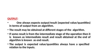
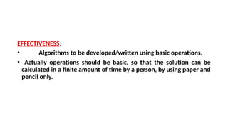
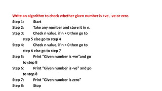
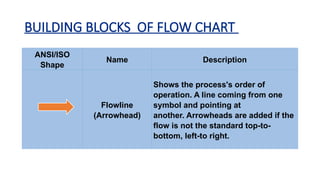
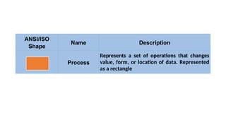
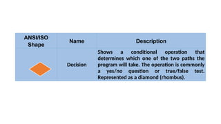
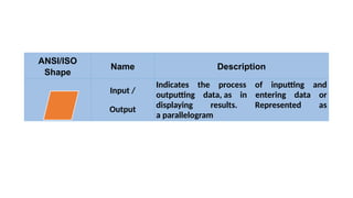
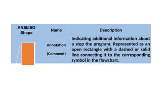
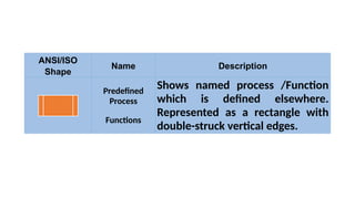
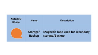
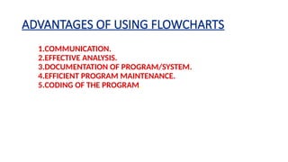
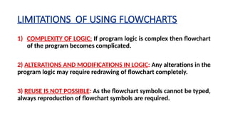
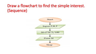
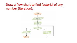
ALGORITHM and
FLOWCHART
•Algorithm can be defined as: “A sequence of
activities to be processed for getting
desired output from a given input.”
•To be an algorithm, set of
rules must be unambiguous and have a clear
stopping point.
What is Algorithm?
PROPERTIES OF ALGORITHM
• Donald Ervin Knuth has given a list of five properties for an algorithm,
these properties are:
1) FINITENESS
2) DEFINITENESS
3) INPUT
4) OUTPUT
5) EFFECTIVENESS
FINITENESS:
• An algorithm must always terminate after a finite number of
steps.
• It means after every step one reach closer to solution of the
problem and after a finite number of steps algorithm reaches to
an end point.
DEFINITENESS
• Each step of an algorithm must be precisely defined.
• It is done by well thought actions to be performed at each step of
the algorithm.
• Also the actions are defined unambiguously for each activity in the
algorithm.
INPUT
• Any operation you perform need some beginning
value/quantities associated with different activities in the
operation.
• So the value/quantities are given to the algorithm before it
begins.
OUTPUT:
• One always expects output/result (expected value/quantities)
in terms of output from an algorithm.
• The result may be obtained at different stages of the algorithm.
• If some result is from the intermediate stage of the operation then it
is known as intermediate result and result obtained at the end of
algorithm is known as end result.
• The output is expected value/quantities always have a specified
relation to the inputs.
EFFECTIVENESS:
• Algorithms to be developed/written using basic operations.
• Actually operations should be basic, so that the solution can be
calculated in a finite amount of time by a person, by using paper and
pencil only.
ALGORITHM EXAMPLES
Write an algorithm to find area of a rectangle.
Step 1: Start
Step 2: Take length and breadth and
store them as L and B?
Step 3: Multiply by L and B and store it
in area
Step 4: Print area
Step 5: Stop
Write an algorithm to check whether given number is +ve, -ve or zero.
Step 1: Start
Step 2: Take any number and store it in n.
Step 3: Check n value, if n > 0 then go to
step 5 else go to step 4
Step 4: Check n value, if n < 0 then go to
step 6 else go to step 7
Step 5: Print “Given number is +ve”and go
to step 8
Step 6: Print “Given number is -ve” and go
to step 8
Step 7: Print “Given number is zero”
Step 8: Stop
FLOWCHART
• The flowchart is a diagram which visually presents the flow of data
through processing systems.
• This means by seeing a flow chart one can know the operations perf
ormed and the sequence of these operations in a system.
• Algorithms are nothing but sequence of steps for solving problems.
• So a flow chart can be used for representing an algorithm.
• A flowchart, will describe the operations
(and in what sequence) are requiredto solve a given problem.
BUILDING BLOCKS OF FLOW CHART
ANSI/ISO
Shape
Name Description
Flowline
(Arrowhead)
Shows the process's order of
operation. A line coming from one
symbol and pointing at
another. Arrowheads are added if the
flow is not the standard top-to-
bottom, left-to right.
ANSI/ISO
Shape
Name Description
Terminal
Indicates the beginning and ending of a
program or sub-process. Represented as
a stadium, oval or rounded (fillet) rectangle.
They usually contain the word "Start" or
"End", or another phrase signaling the start or
end of a process, such as "submit inquiry" or
"receive product".
ANSI/ISO
Shape
Name Description
Process
Represents a set of operations that changes
value, form, or location of data. Represented
as a rectangle
ANSI/ISO
Shape
Name Description
Decision
Shows a conditional operation that
determines which one of the two paths the
program will take. The operation is commonly
a yes/no question or true/false test.
Represented as a diamond (rhombus).
ANSI/ISO
Shape
Name Description
Input /
Output
Indicates the process of inputting and
outputting data, as in entering data or
displaying results. Represented as
a parallelogram
ANSI/ISO
Shape
Name Description
Annotation
(Comment)
Indicating additional information about
a step the program. Represented as an
open rectangle with a dashed or solid
line connecting it to the corresponding
symbol in the flowchart.
ANSI/ISO
Shape
Name Description
Predefined
Process
Functions
Shows named process /Function
which is defined elsewhere.
Represented as a rectangle with
double-struck vertical edges.
ANSI/ISO
Shape
Name Description
On-page
Connector
Pairs of labelled connectors
replace long or confusing lines on
a flowchart page. Represented by
a small circle with a letter inside.
ANSI/ISO
Shape
Name Description
Off-page
Connector
A labelled connector for use when
the target is on another page.
Represented as a home plate-
shaped pentagon.
ANSI/ISO
Shape
Name Description
Storage/
Backup
Magnetic Tape used for secondary
storage/Backup
ANSI/ISO
Shape
Name Description
Storage/
Backup
Magnetic Disk used for secondary
storage/Backup
ADVANTAGES OF USING FLOWCHARTS
1.COMMUNICATION.
2.EFFECTIVE ANALYSIS.
3.DOCUMENTATION OF PROGRAM/SYSTEM.
4.EFFICIENT PROGRAM MAINTENANCE.
5.CODING OF THE PROGRAM.
LIMITATIONS OF USING FLOWCHARTS
1) COMPLEXITY OF LOGIC: If program logic is complex then flowchart
of the program becomes complicated.
2) ALTERATIONS AND MODIFICATIONS IN LOGIC: Any alterations in the
program logic may require re­
drawing of flowchart completely.
3) REUSE IS NOT POSSIBLE: As the flowchart symbols cannot be typed,
always reproduction of flowchart symbols are required.
Draw a flowchart to find the simple interest.
(Sequence)
Draw a flowchart to find bigger number
among two numbers (selection)
Draw a flow chart to find factorial of any
number (Iteration).

EXPLAINS ABOUT ALGORITHM and FLOWCHART.pptx

  • 1.
  • 2.
    •Algorithm can bedefined as: “A sequence of activities to be processed for getting desired output from a given input.” •To be an algorithm, set of rules must be unambiguous and have a clear stopping point. What is Algorithm?
  • 3.
    PROPERTIES OF ALGORITHM •Donald Ervin Knuth has given a list of five properties for an algorithm, these properties are: 1) FINITENESS 2) DEFINITENESS 3) INPUT 4) OUTPUT 5) EFFECTIVENESS
  • 4.
    FINITENESS: • An algorithmmust always terminate after a finite number of steps. • It means after every step one reach closer to solution of the problem and after a finite number of steps algorithm reaches to an end point.
  • 5.
    DEFINITENESS • Each stepof an algorithm must be precisely defined. • It is done by well thought actions to be performed at each step of the algorithm. • Also the actions are defined unambiguously for each activity in the algorithm.
  • 6.
    INPUT • Any operationyou perform need some beginning value/quantities associated with different activities in the operation. • So the value/quantities are given to the algorithm before it begins.
  • 7.
    OUTPUT: • One alwaysexpects output/result (expected value/quantities) in terms of output from an algorithm. • The result may be obtained at different stages of the algorithm. • If some result is from the intermediate stage of the operation then it is known as intermediate result and result obtained at the end of algorithm is known as end result. • The output is expected value/quantities always have a specified relation to the inputs.
  • 8.
    EFFECTIVENESS: • Algorithms tobe developed/written using basic operations. • Actually operations should be basic, so that the solution can be calculated in a finite amount of time by a person, by using paper and pencil only.
  • 9.
    ALGORITHM EXAMPLES Write analgorithm to find area of a rectangle. Step 1: Start Step 2: Take length and breadth and store them as L and B? Step 3: Multiply by L and B and store it in area Step 4: Print area Step 5: Stop
  • 10.
    Write an algorithmto check whether given number is +ve, -ve or zero. Step 1: Start Step 2: Take any number and store it in n. Step 3: Check n value, if n > 0 then go to step 5 else go to step 4 Step 4: Check n value, if n < 0 then go to step 6 else go to step 7 Step 5: Print “Given number is +ve”and go to step 8 Step 6: Print “Given number is -ve” and go to step 8 Step 7: Print “Given number is zero” Step 8: Stop
  • 11.
    FLOWCHART • The flowchartis a diagram which visually presents the flow of data through processing systems. • This means by seeing a flow chart one can know the operations perf ormed and the sequence of these operations in a system. • Algorithms are nothing but sequence of steps for solving problems. • So a flow chart can be used for representing an algorithm. • A flowchart, will describe the operations (and in what sequence) are requiredto solve a given problem.
  • 12.
    BUILDING BLOCKS OFFLOW CHART ANSI/ISO Shape Name Description Flowline (Arrowhead) Shows the process's order of operation. A line coming from one symbol and pointing at another. Arrowheads are added if the flow is not the standard top-to- bottom, left-to right.
  • 13.
    ANSI/ISO Shape Name Description Terminal Indicates thebeginning and ending of a program or sub-process. Represented as a stadium, oval or rounded (fillet) rectangle. They usually contain the word "Start" or "End", or another phrase signaling the start or end of a process, such as "submit inquiry" or "receive product".
  • 14.
    ANSI/ISO Shape Name Description Process Represents aset of operations that changes value, form, or location of data. Represented as a rectangle
  • 15.
    ANSI/ISO Shape Name Description Decision Shows aconditional operation that determines which one of the two paths the program will take. The operation is commonly a yes/no question or true/false test. Represented as a diamond (rhombus).
  • 16.
    ANSI/ISO Shape Name Description Input / Output Indicatesthe process of inputting and outputting data, as in entering data or displaying results. Represented as a parallelogram
  • 17.
    ANSI/ISO Shape Name Description Annotation (Comment) Indicating additionalinformation about a step the program. Represented as an open rectangle with a dashed or solid line connecting it to the corresponding symbol in the flowchart.
  • 18.
    ANSI/ISO Shape Name Description Predefined Process Functions Shows namedprocess /Function which is defined elsewhere. Represented as a rectangle with double-struck vertical edges.
  • 19.
    ANSI/ISO Shape Name Description On-page Connector Pairs oflabelled connectors replace long or confusing lines on a flowchart page. Represented by a small circle with a letter inside.
  • 20.
    ANSI/ISO Shape Name Description Off-page Connector A labelledconnector for use when the target is on another page. Represented as a home plate- shaped pentagon.
  • 21.
  • 22.
  • 23.
    ADVANTAGES OF USINGFLOWCHARTS 1.COMMUNICATION. 2.EFFECTIVE ANALYSIS. 3.DOCUMENTATION OF PROGRAM/SYSTEM. 4.EFFICIENT PROGRAM MAINTENANCE. 5.CODING OF THE PROGRAM.
  • 24.
    LIMITATIONS OF USINGFLOWCHARTS 1) COMPLEXITY OF LOGIC: If program logic is complex then flowchart of the program becomes complicated. 2) ALTERATIONS AND MODIFICATIONS IN LOGIC: Any alterations in the program logic may require re­ drawing of flowchart completely. 3) REUSE IS NOT POSSIBLE: As the flowchart symbols cannot be typed, always reproduction of flowchart symbols are required.
  • 25.
    Draw a flowchartto find the simple interest. (Sequence)
  • 26.
    Draw a flowchartto find bigger number among two numbers (selection)
  • 27.
    Draw a flowchart to find factorial of any number (Iteration).