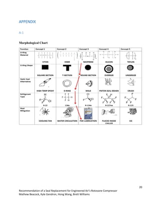
This report provides a recommendation for replacing the seals in Engineered Air's Rotovane compressor. The current Viton seals were found to be degraded due to incompatibility with the POE oil and R134 refrigerant. Through research and simulations, the report recommends replacing the Viton seals with Neoprene seals, which are more compatible with the operating fluids. Installing an oil flush line is also recommended to help cool the mechanical seal and reduce heat-related degradation. Physical testing of the recommended seals in the compressor is suggested to validate the findings.
![8
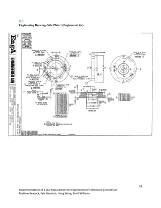
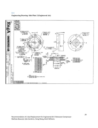
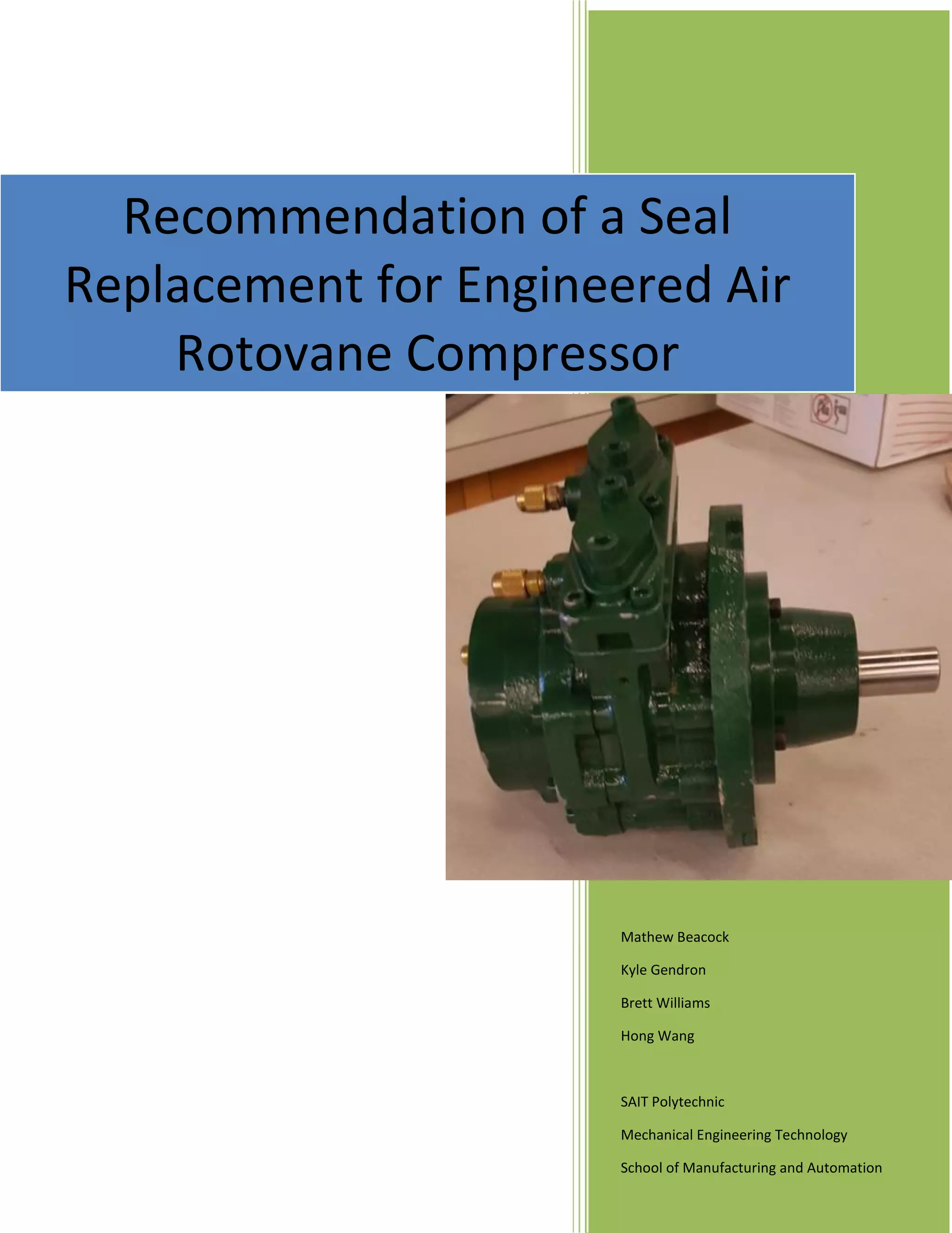
Recommendation of a Seal Replacement for Engineered Air’s Rotovane Compressor
Mathew Beacock, Kyle Gendron, Hong Wang, Brett Williams
When the compressor was received the shaft was very stiff and was not able to be rotated by hand. When
the mechanical seal was removed from the shaft, the shaft was able to turn much more freely. The
working length of the seal was checked using a flat surface table, depth gauge, calipers and micrometers
to make sure there was not too much spring tension on the seal faces. It was found to be at 32.47 mm
which is within its tolerance of 32.5 +/- .764mm. [1][2]. The seal was then re-assembled using lubrication
at the seal faces and it was found the shaft was much easier to turn. This could suggest a possible lack of
lubrication at the seal faces. There is some room to decrease spring tension and stay within tolerance if
necessary, but too much could cause leakage at the seal faces during operation.
DESIGN PROCESS
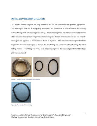
Initially it was just though that the O-ring failure was caused just from the incompatibility of the O-ring
material and the POE oil. After more investigation and complete disassembly of the compressor, it was
noted that the O-ring on the stationary element of the mechanical seal was the most affected. It was
thought that other than incompatibility with the fluids, excessive heat may be affecting the O-ring and
possibly speeding up the chemical degradation of the O-ring.
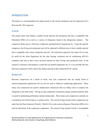
Heat issues
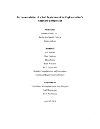
Excessive heat generated from contact between the mechanical seal faces is believed to have an effect on
the failure of the O-ring. Since all of the O-rings are in contact with the same fluid it is believed that there
is another mode of failure at play in this location which could be explained by excessive heat. A heat
propagation simulation of the affected components was performed using Solidworks as seen in Figure 5.
The stationary seal from the mechanical seal, O-Ring and outer housing was modeled and used for the
study.](https://image.slidesharecdn.com/7a3ba74d-3d41-49bb-a8d7-5f9917106fd1-160423022801/85/EngineeredAirGroupB_final_report_7_copies-14-320.jpg)
![10
Recommendation of a Seal Replacement for Engineered Air’s Rotovane Compressor
Mathew Beacock, Kyle Gendron, Hong Wang, Brett Williams
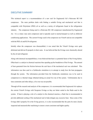
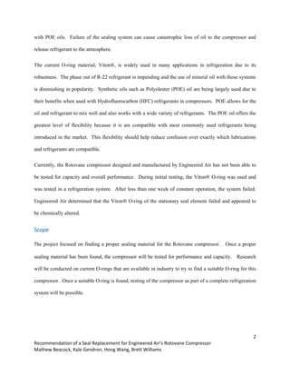
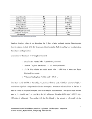
Heat Generation Calculation Process
Figure 6: Seal Face drawing
Calculating the heat generated at the seal face required many calculation:
1. Total face pressure Ptot = △P(B-K)+Psp
2. Mean face Dia. Dm=(Do+Di)/2
3. Running torque Tr=Ptot*A*f*(Dm/2000)
4. Heat generated H=Tr * N / 9548
Assumptions and estimations were made using the procedure outlined by Tom Arnold of Fluor [3].
Seal Face](https://image.slidesharecdn.com/7a3ba74d-3d41-49bb-a8d7-5f9917106fd1-160423022801/85/EngineeredAirGroupB_final_report_7_copies-16-320.jpg)
![12
Recommendation of a Seal Replacement for Engineered Air’s Rotovane Compressor
Mathew Beacock, Kyle Gendron, Hong Wang, Brett Williams
refrigerant but still establishes a good baseline of where to begin. It was also confirmed with Adam
Smolarchuk of John Crane Seals Inc. that a positive flush line is recommended.
“We recommend a positive flush via a flush line (typically Plan 11, which is a line off of pump discharge
into the seal chamber) because it provides both cooling and lubrication for the seal faces. In this
particular case we would recommend 1.5 - 2.5 Gallons per Minute of flush. But it may be hard to
achieve a substantial flush if the suction and discharge differential is very small (as indicated in the
reference drawing).” [4]
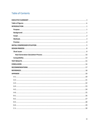
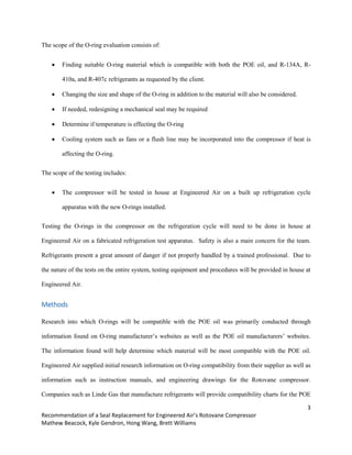
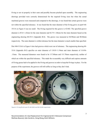
If it is determined that the mechanical seal O-ring is being affected by heat either from excess friction or
lack of fluid flush, then a flush line may need to be installed. The flush of fluid across the seal faces will
help to break through the “corona” which develops from the fluids being superheated between the seal
faces and evaporating into a gas [5][6]. The gas creates a barrier around the seal which prevents fluid
from reaching the seal faces further preventing them from being cooled. We can see in figure 7 the
corona which develops around the seal faces during operation.
Figure 7 - Corona Effect around Mechanical Seal Faces
Source: [6]](https://image.slidesharecdn.com/7a3ba74d-3d41-49bb-a8d7-5f9917106fd1-160423022801/85/EngineeredAirGroupB_final_report_7_copies-18-320.jpg)
![13
Recommendation of a Seal Replacement for Engineered Air’s Rotovane Compressor
Mathew Beacock, Kyle Gendron, Hong Wang, Brett Williams
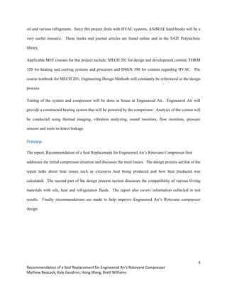
Compatibility
Being able to find an O-ring material for POE oil as well as R-134a refrigerant was the main goal of the
project. Since there are many commercially available O-rings that are suitable with a wide array of
refrigerant and oil combinations, it would be best to use an O-ring that would be compatible with the most
oil and refrigerant combinations as possible. These O-rings would also have to have a large operating
temperature range as the operating temperature of the compressor can vary greatly depending on
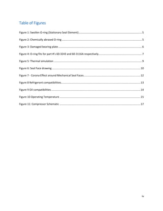
application and running conditions. Many O-ring manufacturers were contacted and compatibility
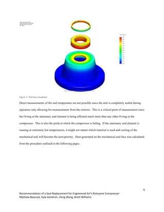
information was collected. Based on data from Parker Seals Inc. as seen in figure 8, it was determined
that the best choice for O-ring material that was compatible with R-134a refrigerant was Neoprene. It
was also found that Neoprene was best suited for refrigerants R-407C and R-410a based on a technical
bulletin released by DuPont Suva [7]. Based on the test data found by DuPont, it appears that Neoprene
is one of the materials less affected by the refrigerants and therefore would be a good choice for use with
a wide variety of refrigerants.
Figure 8 Refrigerant compatibilities
Source: [8]](https://image.slidesharecdn.com/7a3ba74d-3d41-49bb-a8d7-5f9917106fd1-160423022801/85/EngineeredAirGroupB_final_report_7_copies-19-320.jpg)
![14
Recommendation of a Seal Replacement for Engineered Air’s Rotovane Compressor
Mathew Beacock, Kyle Gendron, Hong Wang, Brett Williams
According to Angel Mendez of CPI Fluid Engineering, “Elastomer compatibility in general and
particularly in refrigeration type systems is not always straight forward. The way the elastomer is
affected by heat or cold, harden or soften, swell or shrink, static or dynamic application can sometimes
be considered a negative or even positive outcome depending on the effect. Most of the time the outcome
is swelling of the material, so if swelling is not desired then we would not recommend the use of this
material” [9]
Compatibility with POE oils vary largely depending on the brand and composition of the oil. According
to Stantech Technical Information as shown in Figure 9, it was concluded that the best O-Ring for POE
oil would be either nitrile or Neoprene. Since the Neoprene material is the most universally compatible
with the most used refrigerants, it was determined that the best O-ring to start with would be Neoprene.
Figure 9 Oil compatibilities
Source: [10]
Heat was another issue when it came to selecting a new O-ring. The O-rings selected needed to be within
the operating temperature of the compressor. It was not originally know the actual operating temperature
of the O-ring but was estimated to be approximately 160 degrees Fahrenheit. Based on operating](https://image.slidesharecdn.com/7a3ba74d-3d41-49bb-a8d7-5f9917106fd1-160423022801/85/EngineeredAirGroupB_final_report_7_copies-20-320.jpg)
![15
Recommendation of a Seal Replacement for Engineered Air’s Rotovane Compressor
Mathew Beacock, Kyle Gendron, Hong Wang, Brett Williams
temperature information as seen in figure 9, it was determined that all of the O-ring materials under
consideration under fell into the estimated operating temperature.
Figure 10 Operating Temperature
Source [11]
TEST RESULTS
Initially Engineered Air was to assemble a test apparatus in order to perform a live test-run of the
compressor once it was re-assembled with the new O-rings. The test apparatus will represent a chiller/AC
unit and will comprise of a condenser, intercooler and evaporator. The compressor test will be done by
running the equipment for an amount of time specified by Engineered Air while measuring the capacity,
pressure and other parameters set out by Engineered Air. Since it was believed that heat could possibly
be speeding up the breakdown of the O-ring, temperature will be measured. Since the temperature of the
mechanical seal cannot be directly measured as it is fully sealed and not accessible, a non-invasive
method must be used such as thermal imaging or a readings via laser thermometer. These measurements
will only give us the surface temperature. These measurements will be compared to the Solidworks
simulation that was produced using values based off of the assumed operating temperature and the](https://image.slidesharecdn.com/7a3ba74d-3d41-49bb-a8d7-5f9917106fd1-160423022801/85/EngineeredAirGroupB_final_report_7_copies-21-320.jpg)
![16
Recommendation of a Seal Replacement for Engineered Air’s Rotovane Compressor
Mathew Beacock, Kyle Gendron, Hong Wang, Brett Williams
amount of heat produced from friction as shown in Figure 5. If the external temperature of the actual
compressor reached a certain amount when measured during a live test, it would be concluded that heat is
affecting the O-ring and that could possibly be a cause of failure especially if it is operating outside of the
recommended operating temperature.
Unfortunately there have been many delays with ordering parts for the testing apparatus, Engineered Air
was not able to build up a test apparatus in time and the compressor with the replacement Neoprene O-
rings was not able to be tested in a live test run.
CONCLUSION
Based on the research done with compatibility and heat propagation, it is recommended that Engineered
Air change the O-ring material to Neoprene. Neoprene will be the most universally compatible O-ring for
many of the most commonly used refrigerants. Neoprene material falls within the operating temperature
of the compressor and will be a suitable material as long as the temperature is not too high. The
Neoprene O-rings were purchased from Jeff Christophers of Hi-tech Seals and he also confirmed that
Neoprene was a suitable material for the current situation [12].
Improving the accuracy of machining of compressor parts specifically the O-ring groves in the plates will
ensure that the O-rings will seat properly without the chance of being pinched during assembly and not
creating a proper seal. Having properly seated O-Rings will help to ensure that the compressor seals hold
under operating pressure and that there will be no leakage of any fluids. Installation of a positive flush
line may be necessary in order to break through the “corona” barrier created around the mechanical seal
during operation and keep the mechanical seal within correct operating temperatures. This will ensure
reliable operation of the mechanical seal and increase the overall longevity of the seals life.](https://image.slidesharecdn.com/7a3ba74d-3d41-49bb-a8d7-5f9917106fd1-160423022801/85/EngineeredAirGroupB_final_report_7_copies-22-320.jpg)
![18
Recommendation of a Seal Replacement for Engineered Air’s Rotovane Compressor
Mathew Beacock, Kyle Gendron, Hong Wang, Brett Williams
REFERENCES
[1] Adam Smolarchuk. John Crane Seals. (Feb. 04, 2016). Type 680 Seal Drawing and Tolerances.
Available e-mail: ASmolarchuk@johncrane.on.ca Message: The seal bellows should not over
compress to the point that it is impossible to turn the shaft by hand. But the bellows must
compress properly to ensure sealing during operation. The tolerance for the operating length of
the seal is ±0.030” (or ±0.762 mm).
[2] John Crane Seals, “Type 680 Low-temperature, General Duty All-Alloy-20 Edge-welded Metal
Bellows Seal, [Online]. Available:
https://www.johncrane.com/~/media/J/Johncrane_com/Files/Products/Technical%20Specification
/Seals/TD-670-676-680-8PG-BW-OCT2015.pdf [Accessed February 4 2016]
[3] Tom Arnold. Fluor. “Mechanical Seal Performance and Related Calculations” [Online]
Available: http://turbolab.tamu.edu/proc/pumpproc/p26/ch12_Arnold.pdf [Accessed Mar. 29th
,
2016]
[4] Adam Smolarchuck. John Crane Seals (Apr. 1st
, 2016). Flush line specifications. Available e-
mail: ASmolarchuk@johncrane.on.ca Message: we would recommend 1.5 - 2.5 Gallons Per
Minute of flush.
[5] U.J. Johnson. Purdue University “Design of Seal Cavities in Refrigeration Compressors” [Online]
Available: http://docs.lib.purdue.edu/cgi/viewcontent.cgi?article=2384&context=icec [Accessed
Apr. 06, 2016]
[6] M.R. Bariff. Purdue University “The Effect of Flashing Refrigerant on Mechanical
Shaft Seal Face Temperatures” [Online] Available:
http://docs.lib.purdue.edu/cgi/viewcontent.cgi?article=2253&context=icec [Accessed Apr. 06,
2016]](https://image.slidesharecdn.com/7a3ba74d-3d41-49bb-a8d7-5f9917106fd1-160423022801/85/EngineeredAirGroupB_final_report_7_copies-24-320.jpg)
![19
Recommendation of a Seal Replacement for Engineered Air’s Rotovane Compressor
Mathew Beacock, Kyle Gendron, Hong Wang, Brett Williams
[7] Chemours “Du-pont Technical Information”. [Online] Available:
https://www.chemours.com/Refrigerants/en_US/assets/downloads/h65905_Suva407C_410A_pus
h.pdf [Accessed Feb. 29th
, 2016]
[8] Parker Seals “Super Neoprenes for HVAC”. Technical Bulletin. [Online] Availible:
http://www.parker.com/Literature/O-Ring%20Division%20Literature/ord5724.pdf [Accessed
March 3 2016]
[9] Angel Mednez. CPI Fluid Engineering. (Feb. 10,2016). Compatibility of POE with various O-
rings. Available e-mail: anmz@cpifluideng.com Message: “HNBR or NBR can be an
acceptablecandidate as long as the nitrile content found in the formulation is above 36%.”
[10] Stantech Industries inc, “Alternate Refrigerant Blends and Material Compatibility
With Rubber Materials in Mobile Air Conditioning” Fort Worth Texas, January 1997
[11] Web Seal Inc. “Temperature Compatibility”, [Online] Available:
[http://www.websealinc.com/oring_temperatures.html. [Accessed February 26 2016]
[12] Jeff Christophers. Hi-Tech Seals. (Feb. 16, 2016). O-ring Issues. Available e-mail:
jeff.christopher@hitechseals.com Message: “Here is what my engineer had to say regarding the
info you had provided, sounds like Neoprene is our best option.”](https://image.slidesharecdn.com/7a3ba74d-3d41-49bb-a8d7-5f9917106fd1-160423022801/85/EngineeredAirGroupB_final_report_7_copies-25-320.jpg)