
Recommended
More Related Content
Similar to emc electromagnetics - Nasrin presentation.pptx
Similar to emc electromagnetics - Nasrin presentation.pptx (20)
Recently uploaded
Recently uploaded (20)
emc electromagnetics - Nasrin presentation.pptx
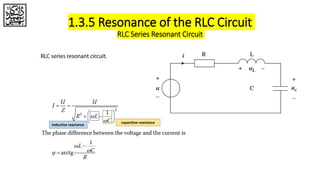
- 1. 1.3.5 Resonance of the RLC Circuit RLC Series Resonant Circuit capacitive reactance inductive reactance
- 2. The changing condition of current I with the frequency of changing in RLC series circuit self‐resonant frequency Series Resonance is used to measure the performance of the resonant circuit when considering the actual frequency characteristics of a capacitor, the equivalent circuit between the two terminals of the capacitor is the series circuit with LCR, while the designers should be more concerned about the voltage between the LCR terminals at this time, not the voltage between the terminals of C Thus, the series resonance can achieve better EMC effects. 1.3.5 Resonance of the RLC Circuit RLC Series Resonant Circuit
- 3. 1.3.5 Resonance of the RLC Circuit RLC Parallel Resonant Circuit
- 4. Relationship between current and frequency in RLC parallel resonance circuit. Parallel Resonance self‐resonant frequency When the resonance occurs, the currents in the two circuit branches I L and I C are approximately equal. At high frequency, the parasitic capacitance between the inductor terminals and the equivalent series resistance of the inductor must be considered. At this time, the inductor can achieve good EMC effect. 1.3.5 Resonance of the RLC Circuit RLC Parallel Resonant Circuit
- 5. 1.4 Common Mode and Differential Mode in the EMC Domain
- 6. 1.4 Common Mode and Differential Mode in the EMC Domain
- 7. 1.4 Common Mode and Differential Mode in the EMC Domain The common‐mode voltage is the voltage causing the common‐mode currents, and the differential‐mode voltage is the voltage causing the differential‐mode currents.
- 8. 1.5.1 Essence of the Radiated Emission Test
- 9. 1.5.1 Essence of the Radiated Emission Test The amplitude study of this common‐mode current that generates the common‐mode radiation is the key to analyzing the radiated emission problem. As shown in Figure 1.21, if the signal is flowing in the antenna with the current amplitude I, frequency F, then the field strength of the radiation at the distance D away from the antenna is When F ≥ 30 MHz, D ≥ 1 m and L < λ/2,
- 10. 1.5.1 Essence of the Radiated Emission Test In the electronic products, there are many unknown details, such as the parasitic capacitance and inductance between the signal lines, the parasitic capacitance between the signal lines and the ground reference plane, the lead inductance of the signal line, and so on. These parameters are frequency‐dependent, and their values are very small, so they are often ignored by the designers in the DC or low‐frequency applications. However, for high‐frequency radiated emission, these parameters are of increasing importance. These factors also generate the undesirable parasitic common‐mode current on the equivalent antenna in the products. Its current magnitude is small (usually below the level of mA or μA), but it is the main cause of the radiation.
- 11. 1.5.2 Essence of the Conducted Emission Test The linear impedance stabilization network (LISN) is the key equipment in the power port conducted emission test. It can be seen from Figure 1.33, the receiver is connected between the 1 kΩ resistor in the LISN and the ground. After the receiver and the LISN are interconnected, the 50 Ω impedance of the receiver’s signal input port is in parallel with the 1kΩ resistor in the LISN, and the equivalent impedance is close to 50 Ω, then it can be seen that, the essence of the conducted disturbance test on the power port is to measure the voltage across this 50 Ω impedance. When the 50 Ω impedance is constant, the essence of the conducted disturbances on the power port can be understood as the amplitude of the current flowing through the 50 Ω impedance. Two currents may flow through the 50 Ω impedance in the real products. One is IDM shown in Figure 1.33, and the other is ICM.
- 12. 1.5.2 Essence of the Conducted Emission Test Controlling the disturbance current not flowing through the 50 Ω impedance is the key to solve the conducted disturbance problem on the power port. The current probe is a key equipment to measure the conducted disturbances on the signal port. It can be clearly seen from Figure 1.34 that the current probe essentially measures the common‐mode current on the cable of the EUT. Of course, just as with the radiation model of the monopole antenna or the dipole antenna, the common‐mode current leading to the conducted disturbances on the signal port is usually not the normal operating current on the signal port, but some undesired common‐mode current. So, the test essence of the conducted disturbance on the signal port is the same as that of the radiated emission generated by the cable or the long conductor, which is equivalent as the monopole or the dipole antenna in the radiated emission test, but the test frequency band will not be the same.
- 13. Thanks for your Attention.