Download to read offline

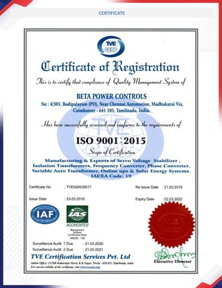


Beta Power Controls is an ISO 9001:2015 certified company established in 2007 in Coimbatore, India, specializing in manufacturing power saving and conditioning equipment. The company offers a range of products, including voltage stabilizers, isolation transformers, UPS systems, and renewable energy solutions, aimed at providing efficient energy for a greener future. With a commitment to quality and customer satisfaction, they focus on continuous improvement and innovative research to meet diverse industrial needs.