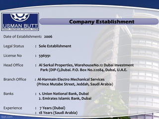
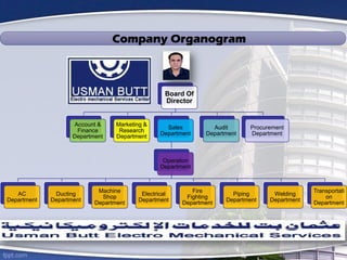
The document provides a company profile for Usman Butt Electro Mechanical Service Company, which was established in 2006. It operates out of Dubai and has a branch office in Jeddah, Saudi Arabia. The company has over 7 years of experience in Dubai and 18 years of experience in Saudi Arabia. It provides various electro-mechanical services, including HVAC, ducting solutions, AC repair and supply, and machine shop services. The company aims to provide quality services and reduce maintenance costs for customers.


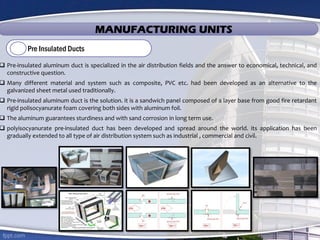
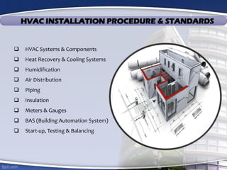
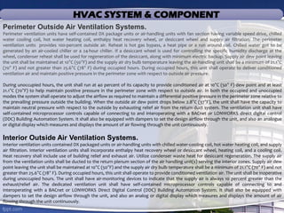

![HVAC SYSTEM & COMPONENT
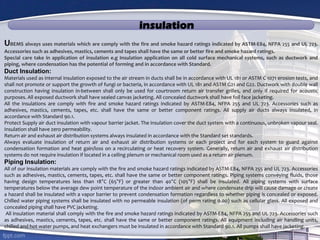
Gas Trains:
Boiler gas trains shall be in accordance with International Risk Insurance (IRI) standards.
Automatic Valve Actuators:
Gas valve actuators shall not contain NaK (sodium-potassium) elements since these pose a danger to maintenance personnel.
Venting:
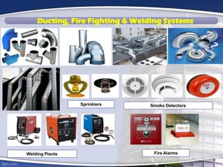
Products of combustion from fuel-fired appliances and equipment shall be delivered outside of the building through the use of
breeching, vent, stack and chimney systems. Breeching connecting fuel-fired equipment to vents, stacks and chimneys shall generally be
horizontal and shall comply with NFPA 54. Vents, stacks and chimneys shall generally be vertical and shall comply with NFPA 54 and 211.
Breeching, vent, stack, and chimney systems may operate under negative, neutral, or positive pressure and shall be designed relative to
the flue gas temperature and dew point, length and configuration of the system, and the value of the insulation techniques applied to
the vent. Venting materials may be factory fabricated and assembled in the field and may be double or single wall systems depending on
the distance from adjacent combustible or non-combustible materials. Material types, ratings and distances to adjacent building
materials shall comply with NFPA 54 and 211.
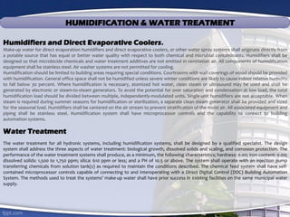
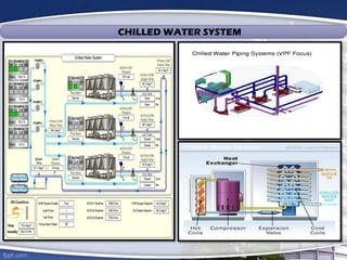
Steam-to-water heat exchangers shall be used in situations where district steam is supplied and a hot water space heating and domestic
hot water heating system have been selected. Double-wall heat exchangers shall be used in domestic hot water heating applications.
Plate heat exchangers shall be used for waterside economizer applications
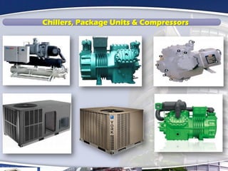
Chillers shall be specified in accordance with the latest Air-conditioning and Refrigeration Institute (ARI) ratings procedures and latest
edition of the ASHRAE Standard 90.1. As a part of the life cycle cost analysis, the use of high-efficiency chillers with COP and IPLV ratings
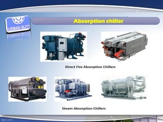
that exceed 6.4 (0.55 kW/ton) should be analyzed. Likewise, the feasibility of gas-engine driven chillers, ice storage chillers, and
absorption chillers should be considered for demand shedding and thermal balancing of the total system.
BACnet or LONWORKS Microprocessor-based controls shall be used. The control panel shall have self-diagnostic capability, integral
safety control and set point display, such as run time, operating parameters, electrical low voltage and loss of phase protection, current
and demand limiting, and output/input-COP [input/output (kW/ton)] information.](https://image.slidesharecdn.com/d2d280d1-bcc7-4266-8f32-6dd4ec6df3a8-150207035859-conversion-gate01/85/company-profile-36-320.jpg)