Aluminium World Journal 2013

Aluminium World Journal is published and distributed once a year to decision makers within the Aluminium industry. Aluminium World Journal provides readers -with exclusive company profiles and editorials - the resources to aid in decision making and management strategies. www.globalmediacommunication.com gmcproduction@gmx.com *Siemens Metals Technologies: The benchmark in aluminium rolling Effective Project management brings a lifetime of benefit for aluminum producers EPC & INDUSTRY PROJECTS *ABB SWITZERLAND: Rio Tinto Alcan ISAL Smelter in Iceland Expansion Project BAUXITE MINING TO ALUMINA * UC RUSAL: UC Rusal Recycling Red Mud PRIMARY SMELTING AND PROCESSES *STAS INC: The STARprobe TM A new technology allowing simultaneous measurements of four crylitic bath properties in only four minutes *ECL: The ECLTM New Concept Furnace Tending Assembly: focus on safety, productivity and Operational costs savings *FLSmidth: MÖLLER Alumina Handling Systems - High performance, high efficiency ANODE PLANT TECHNOLOGY *RIEDHAMMER GmbH *FIVES SOLIOS: HELIOS RT - REAL TIME CENTRAL CONTROL FOR ANODE BAKING FURNACES * STAS INC: World class electrolysis equipment from STAS *BROCHOT GROUP: ADVANCED TECHNOLOGY FROM BROCHOT - A PROVEN SOLUTION FOR ANODE SLOT CUTTING *INNOVATHERM: Upgrade of existing Fume Treatment Plants to cope with higher anode production requirements *ALSTOM: Novel Anode Bake Furnace Gas Cleaning MATERIALS HANDLING AND TRANSPORTATION *RTA ALESA *COPERION GmbH: How should a state of the art vacuum ship unloader look like? CARGOTEC SWEDEN BULK HANDLING AB: Totally enclosed Siwertell technology delivers on all counts * NEUERO: MARKET REVIEW -Developments in Alumina & Pet Coke Ship Unloaders *SMV A/S: FRESH THINKING FOR A BETTER WORKING ENVIRONMENT AND IMPROVED EFFICIENCY CORPORATE PROFILES Rolling Mill *ABB AB FORCE MEASUREMENT Cast House *HYCAST AS *Küttner IST Technology *JASPER GmbH Heat Treatment *SECO/WARWICK GROUP

Recommended
More Related Content
What's hot
What's hot (20)
Similar to Aluminium World Journal 2013
Similar to Aluminium World Journal 2013 (20)
More from Global Media Communication Ltd.
Recently uploaded
Recently uploaded (20)
Aluminium World Journal 2013
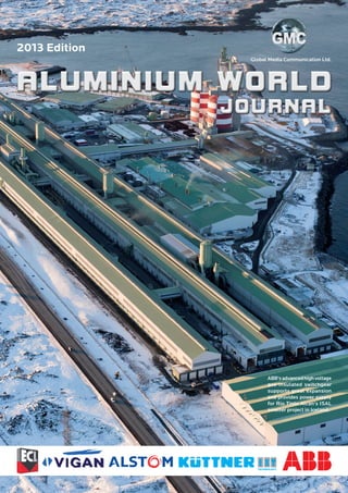
- 1. TECHNOLOGY 2013 Edition Global Media Communication Ltd. ABB'sadvancedhighvoltage gas-insulated switchgear supports great expansion and provides power supply for Rio Tinto Alcan's ISAL smelter project in Iceland.
- 2. 2 www.parsytec.com www.isravision.com Ingot Hot Rolling Cold Rolling Annealing Coil Treatment Coating Finishing Packaging Automotive End Markets „Ensure Higher Quality, Increase Productivity & Improve Process with SURFACE MASTER“ Non-Ferrous Ferrous Aluminium MASTERSURFACE Yield Optimization! … Beyond Inspection! ISRA VISION Provides the Key to Productivity: 25 Years of Experience with Thousands of Installations in More than 20 Countries around the Globe. Always close to You with our Customer Support & Service Team. V I S I O N ISRA Partner With The Global Leader In Surface Inspection. Get MORE Out Of YOUR Production.
- 3. 3AWJ 2013 Foreword By Christopher Fitcher-Harris Aluminium World Journal 2013 features editorials, case studies, company profiles, and product reviews. The publication is divided by industry sector sections to ensure ease of navigation. The information contained in each section provides readers with the tools to reduce operating costs, increase productivity, and increase the life cycle of technology. This edition contains a special feature report produced by Siemens Metals Technologies entitled "The benchmark in aluminium rolling - Effective Project management brings a lifetime of benefit for aluminium producers". I take this opportunity to thank the participating companies for providing Aluminium World Journal 2013 with editorial, company profiles, advertisements and corporate sponsorship. Aluminium World Journal 2013 is available for you to read online, download, and in print format. Visit us online at: www.globalmediacommunication.com If you should wish to discuss with me anything concerning the content of this edition, do not hesitate to contact me. Hope you enjoy the read! Christopher Fitcher-Harris Managing Director Managing Director Christopher Fitcher-Harris, Production Manager Sofia Henriksson Sales Manager Peter Jones Production Design: row1graphics Published by: Global Media Communication Limited Telephone: +44 208 579 0594 E-mail: gmcproduction@gmx.com Website: globalmediacommunication.com The opinions and views expressed in the editorial of content in this book are those oftheauthorsaloneanddonotnecessarily representtheviewsofanyorganisationwith which they may be associated. Material in advertisements and promotional features may be considered to represent the views of the advertisers and promoters. The views and opinions expressed in this book do not necessarily express the views of the publisher. While every care has been taken in the preparation of the book, the publishers are not responsible for such opinions and views or for any inaccuracies in the articles or advertisements. ©2013 The entire contents of this publication are protected by copyright. Full details are available from the publishers. All rights reserved. No part of this publication may be reproduced, stored in a retrieval system or transmitted in any form or by any means, electronic, mechanical, photocopying, recording or otherwise without the prior knowledge of the copyright owner. Cover illustration: ABB Switzerland Ltd. Aluminium World Journal 2013 Global Media Communication Ltd.
- 4. ON-LINE DEFECT DETECTION, IDENTIFICATION AND REPORTING For further information visit www.cognex.com/sisd email SmartView@cognex.com or call: US +1 508 650 4141 Europe +49 721 66390 China +86 21 63517377 Japan +81 35977 5400 REAL TIME INSPECTION OF ALUMINIUM ENABLES FASTER PROCESS CORRECTION AND BETTER YIELD OPTIMIZATION. Surface Vision
- 5. AWJ 2013 INDEX Special Feature p. 7-14 EPC and Industry Projects p. 15-20 Bauxite Mining To Alumina p. 21-24 Primary Smelting and Processes p. 25-34 Anode Plant Technology p. 35-56 Materials Handling And Transportation p. 57-74 Company Profiles p. 75-85 Advertiser and Web Index p. 86
- 6. 6 During the past five decades we have supplied hundreds of new and modernized mills setting the benchmark for producing quality strip in an efficient manner. The market is ever changing and demands highest yield and tolerances while minimizing environmental impact. Siemens VAI is at the forefront of this challenge. As a total solution provider the Dynamic Shape Roll DSR© has been developed as a variable force distribution actuator, replacing a conventional solid back-up roll, Improving mill productivity and reducing operating costs. The DSR© enables you to meet market challenges of today and the future. Your mill will produce a harder, wider and thinner product portfolio ensuring product flatness, increase your schedule flexibility, reduce material breakages and roll changes. The Intelligent flatness control algorithm uses feedback from the shape roll to generate signals to vary the force distribution across strip width. The DSR© ’s performance is impressive; eliminating undesirable roll contact and stress peaks. The control range is considerably larger than 6hi and contoured roll Answers for industry. siemens-vai.com Focus on Precision, Yield and Green design mills. True dynamic control is achieved by fast response of the pads to changes in the force distribution reference. DSR© Benefits: Yield Savings – Achieves target flatness quicker and retains longer during tail out. No warm-up coils required during mill start-up or width change. Rolling passes reduced. Rolling speed increased. Productivity increased (product mix dependant). Number of Back Up roll changes reduced. Retrofitting of DSR© requires minimal downtime and recommissioning. Be the leader in the field – with SIROLL ALU solutions from Siemens VAI, a global supplier and your local partner. Set the benchmark in Aluminum Rolling!
- 7. 7AWJ 2013 SPECIAL FEATURE Siemens Metals Technologies The Benchmark In Aluminium Rolling p. 8-12 Effective Project Management p. 13-14
- 8. 8 GLOBAL ISSUES siemens-vai.com Focus on Precision, Yield and Green Set the benchmark in Aluminum Rolling! Answers for industry. We know what we’re talking about when it comes to aluminum rolling. During the past five decades we have supplied hundreds of new and modernized mills that set the benchmark for producing quality strip in an efficient manner. The market is ever changing and now demands highest yield and tolerances while minimizing environmental impact. Siemens VAI is at the forefront of this challenge. On the basis of immense process know- how and engineering experience, Siemens VAI works with our customers to meet their targets for productivity, quality, yield and flexibility. As a total solution provider, maximum mill performance is assured with the latest equipment design, advanced technological packages, sophisticated electrical, automation, environmental systems, and a full range of vertically integrated supply packages. With specialized technologies for thickness, profile and flatness control, the strictest quality and tolerance demands are met for all downstream product requirements. At every stage of a mill’s productive lifetime, we have the right solution to ensure that your mill performs at its peak level. Our portfolio includes: New plants and mill modernizations Complete equipment supply Electrical and automation systems Consultancy services and mill audits Customized mill products Worldwide, around-the-clock services Be the leader in the field – with SIROLL ALU solutions from Siemens VAI, a global supplier but your local partner. E10001-M1-Z53-V1-7600
- 9. 9AWJ 2013 The Benchmark in Aluminium Rolling Siemens Metals Technologies is a global leader in the Metals Industry, supplying the world’s metal producers and processors with world class equipment and services. Metals Technologies (MT) in the UK is the global Centre of Competence (CoC) for aluminium and Rolling Mills with responsibility for the engineering, supply,installationandcommissioning, and technological development and innovation on a worldwide scale. Siemens MT was established in the United Kingdom 170 years ago and is made up of a merger of a number of companies, namely Loewy Robertson, Davy Corporation, Davy International, Kvaerner Metals and most recently Voest-Alpine Industrieanlagenbau (VAI). The UK team is made up of over 260 highly qualified people with many years of experience based on a strong heritage dating back through the mergers and acquisitions mentioned above. With our sophisticated know- how and our deep experience in aluminium, ranging from hot rolling to the finished product, including cold rolling and foil mills, Siemens MT can meetbothupstreamanddown-stream demands and build the mill that fits the client’s requirements. • Our solution has everything to bring aluminium rolling mills up to speed. This includes:- • The most powerful roll drives for higher throughput • State of-the-art mechanical and hydraulic solutions to optimize performance and operational efficiency • Online process models and neural networks will enable you to produce more accurately than ever before • Proven automation solutions to maximize your plant’s end-to-end consistency • Reliability and security for the future Siemens MT is the only mill builder with in-house capabilities to bring togetherthemechanicalandelectrical technologies in one package. Strategy We use a wide range of specialised technologies such as SIROLL DSR® (Dynamic Shape Roll), SIROLL SmartCrown®, AGC, automatic profile and AFC flatness control along with in- house technological instrumentation to achieve highest product quality. Key to the companies’ success is the Project Management and Quality Management systems which are used within Siemens MT. The systems are based on many years of experience gained from the application in numerous projects and are relevant for both small and larger projects. Project Management ensures for the customer, not only conformity with our quality standards but also that delivery and commissioning take place on schedule, while Siemens MT benefit from the cost and quality control. Siemens MT sources equipment from the global market, whilst ensuring that our quality systems are adhered to by the suppliers. Equipment classed as Intellectual Property (IP) is made exclusively in our own workshops. These manufacturing centres are based in Montbrison, France, Shanghai, China and in Worcester, USA. All these specialised shops build the mills components and provide global support for the mill business. Core Competence Siemens MT supply a range of aluminium rolling mills for hot rolling, coldrollingandfoilrollinginvariousroll configurations and for all strip widths. The full range of cold rolling mills including breakdown mills, tandem mills with two, three, four or five stands and thin strip mills for light gauges including foil roughing are also available. The mill stands are of 4-high or 6-high design and provide the flexibility to cover the complete range of alloys over a wide gauge range. Strip widths are ranging up to 2,100 mm, and future expectations are of widths up to 3,000 mm. Latest references include:- • Three Single-stand foil mills for Shanghai Shenhou in 2006 • Single-stand cold rolling mill for Chinalco Henan in 2011 • Single-stand cold rolling mill for Chinalco South West Aluminium in 2011 • Three-stand hot finishing mill for Chinalco Ruimin in 2011 • Three-stand hot finishing mill addition for Novelis Korea in 2011 • Single-stand 4 metre wide plate mill for Aleris-Dingsheng in 2011 • Single-stand hot reversing mill for Chinalco Nela in 2012 In addition during the last 5 years we have supplied over 200 foil mill Technological Control Systems (TCS) for thickness and flatness control, over 50 system’s were supplied to Dingsheng Aluminium alone. The Chinese market continues to grow andisakeymarketforSiemensMT;this is why Siemens MT has developed a range of foil mill configurations based on a standard design for each mill providing economical solutions, fast delivery and minimised production start-up.
- 10. 10 Key Technologies SIROLL Dynamic Shape Roll (DSR®) The SIROLL DSR® has its origins back in the paper industry with the NIPCO roll from Sulzer Escher Wyss. Paper mills have always tended to be much wider than mills in the metals industry and problems of stability occur at widths above 1,800mm. The SIROLL DSR® was developed to give improved control under these conditions. Siemens MT have now taken this technology and extended it into the metals rolling field. SIROLL DSR® replaces the top solid backup roll usually employed in 4-high stands. It provides improved flatness control, especially in the critical areas at the head and tail ends of the strip. This allows for significant improvements in overall coil yield. Currently the company considers the SIROLL DSR® to be the only truly online dynamic actuator that can enable symmetric and asymmetric changes to the roll gap profile during ongoing production. Operational benefits of the SIROLL DSR® include:- • Head and Tail Flatness – improved yield by achieving flatness guarantees quicker than conventional roll • Overall Flatness – flatness guarantees of less than 3 I units have been achieved with the SIROLL DSR® • Width Changes - with the SIROLL DSR® it is possible to switch rolling widths by considerable amounts (in excess of 600mm) and to still achieve excellent flatness without any warm-up (transition) coils • Cold Starts - these are particularly impressive with a SIROLL DSR®, body of coil flatness of 8 I units after just over 90 metres rolled have been achieved after a prolonged stop-page of sixteen hours on 0.447mm strip at 1,870mm strip width Based on a review of a typical new large cold mill producing around 100,000 tonnes per annum Siemens MT have estimated potential benefits in the order of millions of dollars per year. This of course does depend on the product mix. The savings are approximately evenly divided between the benefits from improvements to the head and tail performance and the ability to minimise out of specification material at width changes. SIROLL DSR® Sectional Diagram SPECIAL FEATURE Cold Aluminium DSR® Mill at Chinalco Henan
- 11. 11AWJ 2013 SIROLL Air Bearing Shapemeter Roll Section SIROLL Air Bearing Shapemeter Roll Withover500referencesworldwidethe SIROLL Air Bearing Shapemeter roll is Siemens MT principle technology for the on-line measurement of flatness for both the Aluminium and Steel sheet and foil applications. The SIROLL Air Bearing Shapemeter roll comprises a series of hardened, precision ground rotors, supported by air film bearings on a stationary stainless steel arbor. This design results in low inertia rotating elements with negligible frictional resistance usuallyinherentinairbearings,thereby eliminating the need for helper drives. Connected by a detachable pneumatic umbilical cord the electronics are mounted remotely from the roll for easy access and protection from harsh mill environments. An array of jets supplies each rotor with air from a common plenum chamber in the centre of the arbor. The differential pressure measured between the top and bottom of the inside of each bearing is proportional to the load applied to the rotor. Hence, the tension is calculated at each rotor position across the width of the strip to provide the tension profile or ‘shape’ of the rolled strip. Each differential pressure output is measured by means of a high integrity pneumatic transducer, which is remotely located in the transducer housing attached to the end of the shapemeter arbor. Each measuring channel has a single moving part, the rotor. All other parts are stationary, includingthemeasurementandsignal transfer elements. The signal outputs provide continuous readings that are independent of mill speed allowing a fast signal response and high accuracy even at low rolling speeds. Key benefits of the SIROLL Air Bearing Shapemeter include:- • Lower Cost Solution – Solid type rolls more expensive • Very Low Inertia Rotors – No drive system required • Very Compact Design – Greater installation flexibility • Simple Design – Low maintenance, can be serviced on site by customer • No Electric's in Roll – Pressure Transducers etc mounted in remote Transducer box • Signal Output – Continuous & independent of mill speed SIROLL Integral Solenoid Valve Sprays (ISV) The SIROLL ISV Sprays is one of the metal industries leading spray valves, with over 300 references worldwide the SIROLL ISV Sprays have been supplied to the rolling industry for over 25 years. Proven extensively in both steel and aluminium industries, the SIROLL ISV Sprays are suitable for all mill types, from hot mills through to aluminium foil mills. SIROLL ISV Sprays Chinalco Southwest Aluminium Mill
- 12. 12 SPECIAL FEATURE The SIROLL ISV Sprays system is designed to apply zone cooling and lubrication to the work rolls. The system removes residual flatness errors and controls the bulk temperature of the mill during the rolling process. Temperature control is achieved by modulating the coolant through individual ISV valves thereby controlling the thermal profile of the work rolls. Nozzle configurations are specifically designed, using advanced thermal modelling, to optimise the spray patterns and coolant flow rates tosuittherequirementsoftheprocess. Schneider® Coolant Filtration Schneider® Coolant Filtration Coolant filtration is an essential element in the rolling and forming of all metals. Since 2004 Siemens MT has supplied the Schneider® Coolant Filtration system for aluminium hot and cold mills, steel, stainless steel, copper/brass mills and for 2-piece can making plants. The market leader in the design, supplyandoperationofmineraloiland emulsion coolant filtration systems, Schneider Filtration ‘know-how’ from SiemensMTwillimproveperformance and product quality throughout the rolling and forming process. The very high levels of filtration achieved for both mineral oils and emulsionswhenusingtheSchneider® Coolant Filtration system maintains the coolant in ‘as-designed’ condition. The system extends the life of the coolant providing an exceptional sheet surface and foil quality. Specific system design features and auxiliary components are unique to the technology. Today’s modern semi- synthetic coolants require a different approach to coolant handling and filtration. Traditional methods do not meetthenewdemandsforcleanerlow smut sheets and for the conditioning of the emulsion to keep the coolant to its original design specification. Filtration to and below the oil drop- By doing this, the optimal thermal performance may be achieved for each and every application regardless of the rolling duty or individual pass schedules. As a complement to the SIROLL ISV Sprays and to minimise shape errors at the strip edge, Siemens MT also offer an integrated Hot Edge Spray System to spray hot coolant outboard of the strip edge to reduce work roll thermal gradients. Key benefits of the SIROLL ISV Sprays include:- • Easy Maintenance • Universal Valve for all Mill Types • Robust Design • Small Installation Envelope • High Reliability • Advanced Thermal Modelling • Stainless Steel Valve let size is easily accomplished with specially designed filter cloth media for depth filtration using multiple layers of different media. Over 1400 Schneider® Coolant Filtration systems are being used today to roll, Aluminium, Steel, Stainless Steel, Copper/Brass, Titanium, Zinc and similar metals. The Schneider® system has become the industry standard in the rolling and can industry. Key benefits of the Schneider® Coolant Filtration include:- • Improved Filtration Performance – less than 10μm • Improved Product Quality • Patented Green Filter Media - safe to handle, no dust hazard • Reduced Waste Streams - zero waste available • Eliminates Coolant Dumps • Low Operating Costs • Improved Process Performance – increased roll life
- 13. 13AWJ 2013 Effective project management brings a lifetime of benefits for aluminium producers Author; Albert Renshaw – Senior Project Manager and PM@Siemens UK Champion (RPP), Siemens VAI Metals Technologies For aluminium producers, when building or modernising a production line, the investment amount required is not the only issue to be considered. Any delays to a modernisation or the belated commissioning of a new line means loss of production and financial revenue. Therefore, choosing the right partner for a project is as important as choosing the right technology. A partner capable of providing effective management from conception to production ensures that an aluminium plant is built on-time and according to specification. This is the basis for maximising value. Professional project management provided on a global stage is a core competence of Siemens and a vital success factor for our customers. Project management is the process by which projects are defined, planned, monitored, controlled and delivered such that the agreed benefits are achieved. In general, more than 50% of Siemens global sales is project- related. In 2001, Siemens embarked upon the global project management programme“PM@Siemens”tosupport the continuous and sustainable improvement of project management processesinallofitsbusinessactivities worldwide. The aim was to establish best practice through the application of knowledge, skills, tools and techniques in order to ensure business excellence. Siemens employs more than 15,000 project managers, all working in accordance with the company values of “excellence, innovative and responsible.” The philosophy is simple; there are clearly defined roles and responsibilities for all those involved in a project. The programme ensures that state-of-the-art processes, methodologies and tools are applied in ways appropriate to the complexity of the tasks. By undertaking both comprehensive training and an internal certification process, Siemens safeguards that its project managers are trained and qualified such that they are able to manage a project On-Going Service & Support Service to existing aluminium producers and new customers is critical to capture new business, customers continue to request the following studies:- • Plant and Mill Studies – studies to investigate ways to increase plant productivity or change specific mill or product parameters which can help clients choose the most cost effective investment route for future plant modernisation • Mill Performance Optimisation Studies – advice from rolling process experts on how to improve and optimise mill productivity within the constraints of the existing equipment • Mill Alignment and Condition Studies – measurement and analysis of the status of existing equipment with corresponding report and recommendations • Spares, Service and Training Support – existing Siemens clients can be offered complete product life cycle services including spares, product training and site support from Siemens service engineers SiemensMTengineeringoffersthefull range of studies as described above and has a number of technological tools and instruments available to provide complete plant analysis, fault identification, FE analysis, and sophisticated reporting. Author: G.Garfitt, BEng (Hons), MIET, CEng, MBA Sales Manager Plate and Aluminium Mills Contact Information: Siemens plc Metals Technologies E- mail: aluminiummill.metals@ siemens.com professionally. Siemens project managers are empowered to do the right things in the right way and at the right time to accomplish the project goals. As a global partner, this means globally uniform procedures that are always executed in a systematic and professional manner by appropriately trained and qualified staff. As a result of the PM@Siemens programme, Siemens was the first corporate company to have its project management programme accredited by the Association for Project Management (APM), itself one of the largest professional bodies of its kind in Europe. The need to find the right partner for a project has already been emphasised. Siemens VAI Metals Technologies is a life-cycle partner for the metals industry. Its UK headquarters, located inSheffield,incorporatestheplateand aluminium rolling mills businesses, including the associated engineering and technology. Mark Chatterton, DirectoroftheSiemensVAIAluminium Business, sees many advantages in leveragingtheengineeringandproject
- 14. 14 SPECIAL FEATURE management experience gained by boththePlateandAluminiumBusiness areas during the recent boom years in the metals market. “Siemens global project management experience is one of our core strengths, which differentiatesusfromourcompetitors. The company is driven to ensure that our project management skills are ‘best practice.’ As part of the company- wide, global project management programme, both plate mill and aluminium mill project teams have demonstrated these skills through the completion of many complex metallurgical infrastructure projects during the last fve years”. These are exciting times for the Siemens VAI Aluminium Business, as a number of high-profile projects have recently been commissioned and put into full operation. The following examplesshowthetypicalbreadthand complexityofprojectsdeliveredbythe Siemens VAI Aluminium group: This project comprises the supply of a single-stand aluminium rolling mill for Aleris Dingsheng Aluminium (Zhenjiang)Co.LtdinJiangsuProvince, China. The rolling mill is designed to produce 250,000 tons per annum of heat-treated and non-heat-treated sheets and plates in widths of up to 4.1 meters. It is the first aluminium plate mill ever to be implemented by Siemens. Commissioning was completed in early 2013. The Siemens supplyscopeincludedmechanicaland electrical equipment for the four-high rolling stand, a hydraulic shear and the roller tables for the new rolling mill. New3-standaluminiumfinishingmill for Novelis Korea Ltd. For this project a new three-stand finishing line was added to the existing rollingmillthatwasoriginallysupplied by Siemens in 1993. The project boosted capacity and enables future production of high-grade aluminum strip for the automobile and beverage can industries. Siemens supplied the mechanical and electrical equipment for this tandem rolling mill, including a coiler and a coil-handling system. Lightweight cropping shears are installed in the entry section of the finishing line. The first coil was rolled in June 2013. The extended hot rolling mill will greatly increase annual capacity and will be capable of rolling strip up to 2,250 millimeters wide with a thickness spectrum from 1.8 to 6 millimeters. Novelis Korea Ltd. is a subsidiary of Novelis Inc. based in Atlanta, Georgia, USA, a leading producer of aluminum and aluminum products. Novelis Inc. operates around 30 production facilities worldwide. The company is the global leader for rolled aluminum products and in aluminum recycling. Recently commissioned projects in China include the 1+4 hot mill at Chinalco Ruimin, the 1+1 hot mill at Chinalco North East Light Aluminium, thecoldmillwithDynamicShapeRolls (DSR) at Henan Zhongfu Aluminium, and the cold mill with DSR at Chinalco Southwest in Chongqing, China. These projects are currently setting the benchmarks for aluminum rolling plantsanddemonstratethebenefitsto be gained from a partner who can offer excellence in project management across all sectors of the industry. Contact Information: Siemens plc E-mail: aluminiummill.metals@siemens. com Follow us on Twitter at: www.twitter.com/siemensuknews The Siemens Industry Sector (Erlangen, Germany) is the world's leading supplier of innovative and environmentally friendly products and solutionsforindustrialcustomers.With end-to-end automation technology and industrial software, solid vertical- market expertise, and technology- based services, the Sector enhances its customers' productivity, efficiency, and flexibility. With a global workforce of more than 100,000 employees, the Industry SectorcomprisestheDivisionsIndustry Automation, Drive Technologies and Customer Services as well as the Business Unit Metals Technologies. For more information, visit http://www.siemens.com/industry Aleris Aluminium Plate Mill Novelis
- 15. 15AWJ 2013 EPC AND INDUSTRY PROJECTS ABB Switzerland Rio Tinto Alcan ISAL Smelter in Iceland Expansion Project p. 16-20
- 16. 16 EPC AND INDUSTRY PROJECTS Rio Tinto Alcan ISAL Smelter in Iceland Expansion Project Introduction The power intensive industry, which is characterised here as manufacturers needing more than 7 MWh/t of their outputproduct,ishighlydependenton the technological development of the manufacturing companies in the areas of products conveying, transforming, switching and controlling power at medium and high voltages. It is of mutual benefit to these companies to cooperate for continuous improvementsofqualityandefficiency of their products and processes. For Rio Tinto Alcan (RTA), HSE (Health- Safety-Environment) aspects of their equipment and production processes are paramount in their evaluation for construction and operation potential. The engineering and production technique of ABB in the field of SF6 insulated switchgear, has presently reached such a level that smelters with high HSE-demands combined with high demands of availability and reliability of equipment, can take confidence in choosing medium voltage switchgear. The specific properties of SF6 are further outlined below. Electrical Properties The excellent dielectric properties of SF6 are attributable to the electronegative character of its molecule. It has a pronounced tendency to capture free electrons forming heavy ions with low mobility, making the formation of electron avalanches very unlikely. The dielectric strength of SF6 is about 2,5 times higher than that of atmospheric air under the same conditions, and this leads to space demand of only 1/10th of conventional air insulated switchgear. This fact is decisive for economical considerations in many cases for voltage levels of 33 kV and higher. Chemical Properties SF6 can be heated to 500°C without decomposition in the absence of catalytic metals. SF6 is non- flammable. Therefore, the risk of ignition caused by an SF6 switchgear malfunction is practically zero, as well as the risk of damage caused by an external fire is as limited as possible. The fault current interruption capability of SF6 is excellent. In its pure state, SF6 is nontoxic, and this is regularly confirmed on new gas prior to delivery, by placing mice in a gas mixture of 80 % SF6 and 20% oxygen for a period of 24 hours (biological test recommended by IEC 376). 220kV AIS Footprint
- 17. 17AWJ 2013 Operation and Maintenance The temperature within an arc in the interruption chamber can be 15 000 K. However, only minor decomposition remnants are present after each interruption. CIGRE WG 23.10 is working on an SF6 recycling guide, covering purity criteria for SF6 SWG. Criteria for handling of SF6 are based on IEC 376 Standards for safety of personnel and environment. These factors contribute in minimizing emissions to the atmosphere. The normal leakage rate of HV Switchgear can be expected to be 0,1 % - 0,5 % per year. Onlyauthorisedpersonnelareentitled to work with SF6 in Iceland and other EEA (European Economic Area – an outer Layer of the EU) countries, as mandated by an EU directive. Two electricians of our substation staff have passed through tests after theoretical and practical training of SF6 Gas Treatment with ABB near Mannheim in Germany. RTA ISAL have acquired special equipment which is dedicated for the sampling, testing, emptying and refilling purposes. RTA ISAL keeps track of its mass of gas by annually weighing the reserve gas and by having SF6 gas detectors in the switchgear room and in the cable cellar connected to the alarm system ofthesubstation.Thepressuregauges of each gas compartment are read off once a week. They are also equipped with a warning and alarm/trip level. Environmental Aspects SF6 does not contribute significantly to stratospheric ozone depletion, as it contains no chlorine, which is the main agent in ozone catalysis, nor to the Greenhouse effect, because the quantities present in the atmosphere are very small. SF6 has infrared absorption characteristics and is considered a minuscule Greenhouse gas, duetoits very long lifetime in the atmosphere. It's contribution to global warming however is very small, due to the extremely low concentration of SF6 in the atmosphere. Assessment on Engineering: Theexperienceofmost,ifnotall,users of SF6 switchgear, for a wide range of operating conditions, is that this technology has brought advantages in performance, size, weight, global costs and reliability. However, for this endeavour to be implemented,itisnecessarytoperform a rigid risk analysis. This is carried out jointly by knowledgeable consultants with experience on operation, the operators and maintenance staff of the owner, and the manufacturer. The findings of such risk analysis and an SQRA (Semi Quantitative Risk Analysis) shall form the basis for the engineering of the switchgear. The modern SF6 Switchgear, as for instance manufactured by ABB in Germany, is an extremely safe equipment against Arc Flash. In spite of this, the standard policy of RTA ISAL is to control it remotely from the control rooms. Switchgear Room: The IPU project (ISAL Production Upgrade) needed space for the installation of 13 bays of 60 kV Circuit Breakers on double busbar. Due to the limited space available near the seaside, accommodating an air insulated switchgear would not have been possible without costly landfill. The gas-insulated switchgear (GIS) technology offered a feasible solution on the available land. It was therefore decided to construct a concrete building beside the two 220/60 kV, 200 MVA, bays for the Step-down transformersfeedingeachhalfof both 60 kV busbars. The link from the ABB’s latest development in GIS has been to reduce the overall footprint drastically Out of the total contribution of all agents, the contribution of SF6 (less than one part in ten thousand, 0,1 promille) is negligible. secondary of these Step-downs is an SF6 insulated busbar.
- 18. 18 EPC AND INDUSTRY PROJECTS degree of precision in the civil part and in installation of transformers and switchgear. Avoiding cable connection here, offers the possibility of undistorted condition analysis of the transformers among other benefts. On the GIS, the local manoeuvring cubicles have indicators for the position of the respective switches. However, for safety reasons, normally the manoeuvring of the switches takes place at the substation’s SCADA system, or in one of the two new Control Rooms constructed by IPU. The GIS-room is fitted with an overhead crane. This was integrated with the installation of the switchgear, and can be utilized in repair of the switchgear if required. The GIS is not particularly maintenance demanding, but ISAL intends to incorporate it in its switchgear maintenance scheme, recording the pattern of the control circuit of the trip coils, the pattern of the main current under the interruption period and to record the length of the total interruption period. Control System ISAL‘s main substation is supervised by an Allen-Bradley Control Logix controller, SuperMaster, that monitors the status of high voltage and auxiliary equipment, interfaces with Landsnet, the national grid operator, and controls transformer cooling, filter banks and collects usage data (energy, water consumption, etc.). Landsnet can enforce automatic curtailment of plant load remotely from their National Control Centre. The required load reduction is divided among the potlines and adjusted for plant power variations by the SuperMaster. The new high voltage (HV) equipment transformers, 220kV air-insulated switchgear (AIS) and 60kV gas-insulated switchgear (GIS) are controlled and supervised by ABB Relian protective relays. A communication gateway, ABB COM600, passes information between the protective relays (status, process values, commands, etc.) and SuperMaster, as well as the InTouch SCADA system. In case of failure of the plant‘s SCADA system, the COM600 can be used for supervision and control of the HV equipment. Each of the potlines is controlled, protected and supervised by its respective potline current controller. PL1 and PL2 are controlled by state of the art A-B Control Logix controllers and PL3 by an ABB Controller (PSR). The existing diode rectifer units of PL1 and PL2 are directly controlled by their potline controllers, but rectifier units of potline 3 are each controlled by an ABB PSR. In case of a potline master controller failure, all rectifier units can be operated manually in stand- alone mode. The new rectifier units are each controlled by a specialized ABB AC 800 PEC rectifier controller. The new units fulfill the same requirement, as the existing ones, of being able to provide current to their potline in the absence of a potline controller, in a stand-alone mode. Communications: As the IPU project was one of integrating new equipment with existing equipment, several communication paths had to be developed. • SuperMaster / COM600 communicate through a serial link using the IEC 60870- 5-101 protocol. A ProSoft module for the Control Logix platform is used This technique demanded a high
- 19. 19AWJ 2013 and software was developed to pass information and commands back and forth. • InTouch SCADA / COM600 as well as Relian / COM600 communicate over Ethernet using the IEC 61850-8-1 protocol. Paths 1) and 2) are completely independent, allowing the SuperMaster to supervise operation and to generate redundant alarms/ warnings in case of break down of COM600 / SCADA communications. • SuperMaster / PML power monitoring devices ION 7600 communicate through an RS-485 link using the Modbus RTU protocol. A ProSoft module for the Control Logix platform is used and software was developed to collect data from the intelligent power meters. Supervision and redundant control of plant power transformer OLTC voltage regulators (21 kV) is also done via a Modbus link. • InTouch SCADA / PML power monitoring devices communicate over Ethernet. A proprietary Schneider Electric (ex. Power Measurement Limited of Canada) ION Enterprise system collects detailed data from the ION 7600 meters, transients, sag/swell, power quality and historical data into a MS SQL database. • Potline Controllers PL1 and PL2 / AC 800 PEC rectifier controllers communicate over Ethernet using the EtherNet/IP protocol. The interface on the PEC side is an Anybus module developed by HMS Industrial Networks. As the EtherNet/IP Anybus module‘s implementation allows only point to point communication, gateways were required for the swing units S1 and S2, as they can be connected to any potline and therefore have to be able to communicate with all the potline controllers. The seamless integration of the PEC controllers of the rectifier units makes them appear as Allen-Bradley equipment to the rest of the world (SCADA, MES, potline controllers, etc.) • Potline Controller PL3 PSR / AC 800 PEC rectifier controllers S1 and S2 communicate over an ABB proprietary PowerLink using an ABB PSR-PSR protocol. • The four AC 800 PEC controllers communicate with each other through a dedicated redundant PowerLink. In Conclusion As demonstrated by the Rio Tinto Alcan Isal Smelter Production Upgrade project, GIS can be integrated into existing facilities to support expansion and power supply for smelters with high energy and health and safety requirements. SF6 insulated switchgear is an enviromentally friendly and safe technology, with excellent operational capacities. An upgrade can be fully tailored through engineering solutions to work with, and around, existing technologies, even where space restrictions may need to be considered. Futhermore, the communication and control systems are designed to integrate seamlessly with existing ones, to provide flexibility and economical advantages, while securing optimal performance. Authors: Bjarni Jonsson, RTA ISAL Leader of the Electrical Services, Haflidi Loftsson, Staki ehf Chief Engineer and Max Wiestner, Head of the Aluminium business within ABB
- 20. 20 SURFACE INSPECTION ABB’s history of powering primary aluminium plants started 45 years ago. Since then, we have supplied complete electrification solutions and substations to more than 60 aluminium smelters worldwide. The modernization of an existing plant to the latest standards and production and efficiency levels – performed while it is still in operation – requires a different set of skills and competencies than building a green- field plant. ABB has in-depth knowledge of the aluminium production process and the experience necessary to execute complex projects – always with the objective to keep your production running day and night. For more information, visit us at www.abb.com/aluminium Keeping your production running day and night? Certainly. Global Product Group Aluminium 5405 Baden 5 Dättwil, Switzerland aluminium@ch.abb.com
- 21. 21AWJ 2013 BAUXITE MINING TO ALUMINA UC Rusal About UC Rusal p. 22 Recycling Red Mud p. 23-24
- 22. 22 About UC RUSAL UC RUSAL is a leading, global producer of primary aluminium and alloys with a particular focus on the production and sale of value-added products and one of the world's major producers of alumina. Thecompany’scurrentcapacitymeans it is able to produce 4.7 million tonnes of aluminium, 11.5 million tonnes of alumina and 80 thousand tonnes of foil per annum. In 2012 RUSAL accounted for approximately 9% of global production of aluminium and 8% of alumina. RUSAL operates in 19 countries on 5 continents. The company employs 72,000 people across the globe. RUSAL’s assets include 15 aluminium smelters, 12 alumina refineries, 8 bauxite mines, 3 aluminium powder plants, 3 silicon factories, 3 secondary aluminium plants, 4 foil mills, 2 cryolite and 2 cathode plants. Within its upstream business, UC RUSALisverticallyintegratedtoahigh degree, having secured substantial supplies of bauxite and alumina production capacity. The Company’s core smelters, located in Siberia, Russia, benefit from access to stranded low-cost hydro generated electricity enabling it to be a low- cost producer of aluminium, with its principal Siberian facilities in close proximity to important European and Asian markets. The Company’s key sales markets are Europe, Russia and the CIS countries, NorthAmerica,South-EastAsia,Japan andKorea.Themajorendusersconsist of over 700 companies representing transport, construction and package industries. RUSAL has a strong growth potential – around 1 million tonnes of attributable aluminium capacity are currently under construction (equivalent to 25% of the current Company’s production volume): - The BEMO Project, which involves the construction of the 3,000 megawatt BEMO HPP and BEMO aluminium smelter in the Krasnoyarsk region of Russia with a design capacity of 588 thousand tonnes of aluminium per annum; - The Taishet aluminium smelter in the Irkutsk region of Russia has a design capacity of 750 thousand tonnes of aluminium per annum. The company was founded in 2000 and, following its merger with SUAL and the alumina assets of Glencore, becametheglobalaluminiumindustry leader in 2007. RUSAL has a 27.8% interest in Norilsk Nickel, the world’s largest producer of nickel and palladium and one of the largest producers of platinum and copper. Together with Kazakhstan’s National Welfarefund“Samruk-Kazyna”RUSAL is developing the Ekibastuz coalfield in Central Asia. RUSAL is currently focusing on strengthening its competitive advantages, including low production cost, considerable raw material base, proprietary R&D capabilities and proximity to key markets. RUSAL owns proprietary smelting technologies (RA-300, RA-400 and RA-500) and is developing new ones, including a revolutionary inert anode technology. RUSAL’s ordinary shares are listed on The Stock Exchange of Hong Kong Limited (Stock code: 486). Global depositary shares representing UC RUSAL’s ordinary shares are listed on the professional board of NYSE Euronext Paris (RUSAL / RUAL). Russian depositary receipts representing RUSAL’s ordinary shares are listed on the Moscow Exchange (RUALR/RUALRS). RUSAL's shareholders are En+ (48.13%), ONEXIM Group (17.02%), SUAL's shareholders (15.80%), Glencore's subsidiary Amokenga Holdings (8.75%) and RUSAL's management. There is a 10.03% free-float. Official website: www.rusal.com UC RUSAL is a leading global aluminium producer. BAUXITE MINING TO ALUMINA
- 23. 23AWJ 2013 Recycling red mud Annual world aluminium production is expected to break the 50,000,000 tonnes barrier this year. Making one tonne of aluminium requires about two tonnes of alumina. The production of two tonnes of alumina creates from two up to four tonnes of red mud or bauxite residue, presently waste from the Bayer process and a potentially valuable resource. The total amount of bauxite residue produced in the world annually is estimated at around 200 million tonnes. Red mud is a mineral residue left after the extraction of alumina from bauxite in the course of the Bayer Process, the principal industrial method of processing bauxite ores into alumina. Bauxite is one of the most complex industrial ores, containing almost all elements of the periodic table in different quantities with alumina being the predominant component (making some 30 to 60% mass of all ore components). Other major oxides With todays technology, alumina and sometimes gallium are the only commercial products being extracted from bauxite ores. constituting industrial bauxites are Fe2O3 (from 5 to 25% mass, SiO2 from 1 to 9 %, TiO2 from 1 to 7 %). Like most ores and soils, bauxite can also contain trace quantities of metals such as beryllium, cadmium, chromium, lead, manganese, arsenic, mercury, nickel and naturally occurring radioactive materials. To achieve extraction of the main components, more advanced technologies are to be evolved. With today’s technology, alumina and sometimes gallium are the only commercial products being extracted from bauxite ores. Correspondingly, bauxite residue is primarily composed of the insoluble in the alkaline Bayer liquors fraction of the bauxite ore, and some Ca and Na aluminosilicates formed in the process as secondary reactions. At present, the amount of bauxite residue being processed is limited. Alumina production waste is mainly disposedofinspecialfacilitiesknownas bauxe residue disposal areas (BRDAs). Due to the Bayer process, red mud has residual alkalinity. The pH level of the residue is generally up to 13 or higher in some cases, due to the presence of alkaline sodium compounds, such as sodium hydroxide. Because of the very small sizes of bauxite residue particles (less than 100 microns) it can be easily carried by wind over fairly long distances from BRDAs. To prevent the red mud from being carried out from BRDAs and causing harm to the environment or people, differentmethodsarebeingusedsuch as construction of new BRDAs with special membranes and protective layers,drydisposal,'slopeddeposition' etc. With regards to RUSAL, the company pays very special attention to the environmental safety at all of its operations and constantly monitors the situation at each of its BRDAs. Treatment methods include reducing pH by carbonation, washing with large quantities of seawater adding gypsum, other amendments such as bitterns, (all of which replace sodium with more favourable elements such as calcium and magnesium) as well as increasing
- 24. 24 Chinese national governments. For instance, RUSAL's recycling project was supported by the Ministry of Science as a next-generation technology. RUSAL's involvement in the red mud recycling project is one of themainfocusesofthecompanyinthe sphere of environmental stewardship. RUSAL’s Engineering and Technology Centre is the project's engine, which is supported by a think-tank, consisting of major Russian technology and engineering partners. The Chinese government has set a target of recycling 10% of all of its red mud by 2015, and our Chinese colleagues from Chalco have already introduced several solutions taken from the iron and rare-earth metals extraction industry, to use the residue for the steel and concrete industry. TherecentmemorandumbetweenUC RUSAL and Chalco foresees joint R&D projects, and we hope that together we can find ways to solve the red mud problem. At present, the recycling of alumina productionwasteisaglobalchallenge. The maximum recycling rate is about 30% for an individual plant. Worldwide bauxite residue processing does not exceed5milliontonnesperyear,which means that less than 1/40th of the amountproducediscurrentlyrecycled. The industry targets regarding the red mud problem are quite ambitious. The International Aluminium Institute predictsthatatleast25%ofallredmud will be recycled by 2025. This means that a comprehensive technology for complete bauxite residue processing to marketable value-added products is required to be developed. Bauxite is one of the most complex industrial ores, containing almost all elements of the periodic table. organic matter content by mixing in organic waste or establishing grass pasture to initiate the nutrient cycle. ThisisthecaseofQueenslandalumina refinery (QAL) in Australia (RUSAL owns a 20% stake in the refinery), where red mud is neutralized with seawater. Onewayoranother,themajorproblem is that there is no established bauxite residue processing technology that would be able to be applied at all the aluminarefineriesintheworldbecause the bauxite composition (depending on the deposit) differs greatly. Finding a way to utilize the red mud in other industries, instead of disposing it in BRDAs, could develop as the best solution moving forward. Today bauxite residue can be used in the steel industry as an iron- containing raw material, in cement production, road construction as well as in agriculture. A part of the bauxite residue is used as an absorbent of industrial gas, to treat industrial and municipal wastewater, as a reductant for soil, absorbent of heavy metals and other harmful substances, as a coagulant, pigment, catalyst and ceramic. RUSAL, which is one of the world’s largest alumina producers, is now building a pilot recycling plant at the Ural aluminium smelter (UAZ), Russia with an annual capacity of 40,000 tonnes looking to expand it up to 200,000 tpa. According to our analysis, the demand for red mud and its byproducts stands at 3 million tonnes per annum from Russian enterprises only, which can easily generate a return on planned investments. The main consumers of the plant in Russia will be the iron and steel industry and the construction sector. Following the launch of this facility, UAZ will establish red mud treatment operations, -creating a new niche on the market- furthering the potential to implement the technology in other RUSAL plants. Red mud recycling technologies are being cultivated by the Russian and BAUXITE MINING TO ALUMINA Bauxite residue can be used in the steel industry as an iron- containing raw material.
- 25. MÖLLER® Alumina ©DUBAL Expertise in ©NorskHydro 25AWJ 2013 PRIMARY SMELTING AND PROCESSES STAS Inc. THE STARprobe™ p. 26-27 ECL The ECL™ New Concept Furnace Tending Assembly p. 28-31 FLSmidth MÖLLER Alumina Handling Systems p. 32-33 Riedhammer Carbon Baking Technology p. 34
- 26. 5 1 7 7 3 8 2 4 26 PRIMARY SMELTING AND PROCESSES The STARprobe™ A new technology allowing simultaneous measurements of four cryolitic bath properties in only four minutes 1- Cart 2- Reusable probe tip 3- Probe 4- Electronic probe head 5-Interface computer 6-Power unit 7- Battery pack 8-Telescopic towing arm During the last 10 years, Alcoa has developed a new device called the STARprobe™ [1, 2, 3]. This technology, now available through STAS, is a portable device that takes real time measurements of four bath properties in electrolysis cells: Superheat Temperature Alumina concentration Ratio (excess AlF3) (STAR) This synchronicity of measurements is the most important step forward in improving the control and efficiency of electrolysis cells. Figure 1 shows one STARprobe™. The device kit consists of a mobile cart and two probes, one communication panel, one interface computer, one power unit, one battery pack and a telescopic towing arm in the front. How it works The probe concept consists in making a Differential Thermal Analysis (DTA), which is a proven method [4], on a bath sample and a reference. The reusable Figure 1: STARprobe™ device kit probe tip (Figure 2) includes two high-precision type K thermocouples, dynamically paired for compatibility. The thermocouple on the left records thecoolingrateofthebathsample,while the thermocouple on the right records the cooling rate of the reference. During the cooling process – the bath sample liquidus temperature – cryolite starts to solidify, which slows the bath sample cooling rate even further. At the eutectic temperatureofthebathcryolite-alumina phase diagram, the alumina starts to solidify as well. Finally, at a much lower temperature -that has reduced down to the eutectic temperature of the bath cryolite AlF3 phase diagram (Figure 1 of [1]) -the excess AlF3 finally solidifies. The reference temperature is selected as the X coordinate instead of the time, so the analysis results of the bath sample are not affected by fluctuating ambient conditions [1]. In fact, the shape of the curve depends on two things only: the design of the probe tip and the composition of the bath sample. This means that for a given probe tip design, the shape of the curve is solely dependant on the composition of the bath sample. The correlation algorithm is very fast, and the calculated results are equivalent to the XRD analysis, as presented [1] and as independently verified on many occasions so far by the author in demonstrations performed in smelters all around the world (for example, see [5]). How it is used in the potroom The reusable, consumable probe tip can take around 100 measurements. It is connected to the probe head through a probe lance, as seen in Figure 3. An operatorcanusetwoofthoseassemblies to measure cells simultaneously. That way, a trained operator can obtain an average time of just under 4 minutes per measurement. Figure 3: Probe assembly The probe head includes a very high resolution electronic thermocouple readerthatreadsthethermocouplesand transmits data via Wifi to the tablet PC running the STARprobe™ application. One tablet PC can simultaneously process the data from the two probe heads. After a few seconds, the results are displayed on the tablet screen (left side of Figure 4), stored in a file on the tablet and can be transmitted automatically to the plant database and/ or to the pot control system. Figure 4: STARprobe™ application displaying the results ONE STEP AHEAD
- 27. 3 12 27AWJ 2013 1 Sample cup Contains bath sample 2 Reference side Provides a reference cooling curve 3 Thermocouple connectors Measures temperatures Figure 2: Reusable probe tip Potential of process control improvements using the STARprobe™ The conventional way to control the bath ratio and the temperature is to regularly take bath samples and measure the bath temperature. Most of the time, bath sampling is not synchronized with bath temperature measurement. In any case, due to the delay in getting the bath sample analyzed, the cell controller typicallyneverreceivesnewtemperature and ratio data at the same time. This lack of synchronicity between the bath ratio and bath temperature data and the lag in getting the ratio data can be totally eliminated by using the STARprobe™ to measure both parameters at the same time and by immediately transmitting the results to the database and to the pot control system via Wifi . Furthermore, a typical bath ratio control logic uses the data for both the bath temperature and bath ratio in order to control the bath ratio by adjusting the amount of AlF3 added to the cell, assuming a given and constant cell superheat. As presented in [7], any inconsistencies between the target bath ratio and the target bath temperature can create instabilities in the feedback control loop. Since the STARprobe™ also measures thebathsuperheat,thebathratiocontrol and the bath temperature control – or rather the bath superheat control – can be decoupled. The bath ratio can be controlled by adjusting the amount of AlF3 andthebathsuperheatbyadjusting the target cell pseudoresistance independently [8]. Improvements have already been achieved in more than 10 of Alcoa’s plants in terms of process control. In parallel with the development of the STARprobe™,Alcoahasdevelopedanew cell controller called QLC which takes full advantage of its STARprobe™ bath properties measurement technology. The QLC automatically acquires the results of STARprobe™ measurements in real time via Wifi [1,6]. The gains guaranteed by Alcoa [6] are the following: • 0.5% current efficiency (proven) • 35 mV voltage savings (proven) • 5% AlF3 savings (proven) • 100-150 day potlife improvement (still to be established) • One time capital cost saving (X-ray equipment) (proven) • Labor savings for sampling/ analysis (proven) • Improved understanding by operators (proven) The STARprobe™ technology is a new way to control electrolysis cells. Other companies around the world have already taken advantage of this new opportunity. STAS is the exclusive supplier for the STARprobe™ technology and offers demonstrations upon request: www.stas.com/en/starprobe References [1] Xiangwen Wang, Bob Hosler and Gary Tarcy, Alcoa STARprobe™, Light Metals, (2011), 483-489. [2] Bob Hosler, Xiangwen Wang, Jay Bruggeman and Patrick O’Connor, Molten Cryolytic Bath Probe, US patent no. 2005/0069018 A1. [3] Xiangwen Wang, Bob Hosler and Gary Tarcy, Systems and Methods Useful in Controlling Operation of Metal Electrolysis Cells, US patent no. 2007/0295615 A1. [4]R.C.Mackenzie,DifferentialThermal Analysis, Academic press London, 1970. [5] M. Dupuis, P. Bouchard and J.-P. Gagné, Measuring bath properties using the STARprobe™ , 19th International ICSOBA Symposium (2012). [6] Wang, X., Tarcy, G., Batista, E. and Wood, G. Active pot control using Alcoa STARprobe™, Light Metals, (2011), 491-496. [7]M.Dupuis,ExcessAlF3concentration in bath control logic, National Conference on Advancements in Aluminium Electrolysis, Indian Institute of Metals, Angul Chapter, (2006). [8] M. Dupuis and J-P. Gagné, Testing a new STARprobe™, ALUMINIUM 89 (2013) 1/2, 76-79. Contact Information: PierreBouchard,Eng.,M.Sc.-President Telephone Office: + 1-418-696-0074 ext. 2222 bouchard.pierre@stas.com www.stas.com Jean-Pierre Gagné, Eng., M. Eng. – Technical Manager, Electrolysis and Carbon Technologies : Telephone Office: + 1-418-696-0074 ext. 2417 jpgagne@stas.com www.stas.com
- 28. 28 Innovation in motion Innovation is in everything we do and in all the equipment we design and build. For over 60 years, ECL™ has been the benchmark for reliable, high quality and cost-effective equipment for aluminium smelters, for all technologies. We will maintain that focus now and in the future. www.ecl.fr
- 29. 29AWJ 2013 The ECL™ New Concept Furnace Tending Assembly: Focus on safety, productivity and operational costs savings Since the first Furnace Tending Assembly (FTA) commissioned by ECL™ in 1963 in Slatinia, Romania, the design and tasks of this machine have evolved. For the first time in industry history, ECL™ has performed a total rethink of the FTA, based on: • A modular structure providing higher performances in terms of: safety, shorter commissioning time, productivity, quality and operational cost savings. • A streamlined architecture - providing significant weight and height reductions. • Better, faster and more efficient coke suction flow rates and enhanced speed in tool movement. • The possibility to have one or two grabs and/or one or two filling pipes on the crane. • An evolutionary design greatly improving maintenance access, costs and ergonomics. ECL™ has focused its efforts in safety, productivity and operational costs- savings in order to deliver a new concept FTA achieving maximum availability and reliability. A modular and streamlined structure Most FTAs consists of a twin girder cross travel structure supporting a tools trolley. Each machine is tailor- made for the smelters following the specific requirements and technical imperatives of the production technology used. The ECL™ New Concept FTA is based on a modular structure, that offers several advantages over conventional designs. It’s lighter than a regular crane. As the FTA is the main piece of equipment supported by the baking furnace building’s rails, this weight reduction has a direct impact on their design and cost requirements. The modular concept leads to a simplification of the FTAs overall structure. Each of the crane’s constituting elements and the links between them (pneumatics, electrics and optical) have gone through a total rethink that makes them individual modules rather than imbricated elements. The resulting crane is faster to commission and easier to maintain. Furthermore, the location of the FTA tools (dedicated for working on the pits) has been modified to greatly improve the operator’s visibility. Consequently the accuracy of tools’ movements is improved, - reducing the potential of damage on the tools and flue walls. The modularity of the cranes also allows flexibility with regard to implementing upgrades. A second grab and/or a second filling pipe, can be installed on a machine to facilitate a possible increase in anode production. Whereas the design of all FTAs is made according to the customer’s requirements, the ECL™ New concept FTA leaves room for further enhancements and future developments.
- 30. 30 PRIMARY SMELTING AND PROCESSES Environment, Health and Safety first In harsh environments with heat, gas, and dust; it is essential to prioritize environment, health and safety for the smelter and above all the operators. The Research & Development department of ECL™ had a strong focus on providing an ergonomic cabin, paying special attention to air quality and temperature control, visibility, safety and reliability. To minimize the safety risks (falling, pinching, crushing, suffocation) ECL™ has equipped its crane with the following safety features: • Retractable step ladder with guardrail to access the crane. • An emergency evacuation access - whatever the position of the main trolley - in case of power cut or damages on tools in the furnace. • Higher number of emergency stops and push buttons. • Improved lighting - accomplished by relocation of floodlights to minimise shade interference. Further, the cabin itself has been subject to many changes and transformed into a shell around the operator. The cabin is more spacious: itssizeincreasedby75%.Thenewsize of the cabin brings many advantages. The operator benefits from a 70% widerwindowarea,providingabrighter environment and better visibility. With a visibility range of 10 metres under the cabin, the operator is now able to see the bottom of the pit which makes the operation of coke filling and sucking much easier. 2 to 3 people can fit in the cabin simultaneously, which offers a great opportunity for training and management purposes. The seats have been rethought and are now motorized - enabling cross travel movements to facilitate and guarantee seat position accuracy perfectly in front of the tools. The seat includes height adjustment as well as air and mechanical suspension, arm support and body fixation for greater ease and flexibility. As an additional option cameras can be installed on the suction pipe, which will eliminate back bending and improve the overall safety observation. The operator can also adapt the control units (joystick) according to his morphology. The smooth driving of the FTA is therefore facilitated and fatigue of the driver considerably reduced. An easy maintenance, safer and cheaper By redesigning its FTA, ECL™ has significantly improved the working environment for the operator, as well as enabled maintenance works to be carried out - which was previously problematic due to the difficult access to key areas of concern. The New Concept FTA is now equipped with several onboard platforms and access points, including: New cabin; more spacious, better visibility and improved ergonomy
- 31. 31AWJ 2013 • A complete upper platform giving full access to the grab hoist unit, the top of the storage hopper (sucking pipe elbow) and the top of the filter hopper to perform filter bags changing. • Maintenance platform, which provides access to the valve situated between the cyclone and the filter hopper as well as the valve used to control the de- dusting sucking during the pit filling phase. • A platform situated at the top of the sucking pipe. • Direct access point to the 25 metric tons hoist, situated above the main trolley. • Direct access point situated between the top of the FTA girder and the long travel maintenance platform. • Lifting points and lifting rails - installed directly on the crane - to facilitate dismantling of the heavy components that are not directly a accessible (moto-reducer, air condition unit, hoist unit). No effort has been spared in ensuring thesafetyforboththeoperatorandthe maintenance staff. The large number of onboard platforms puts an end to having to rely on any cumbersome external mobile platform, which is usually unavailable when required. A New Concept FTA combining reliability and greater performance A double filling pipe The new architecture of the FTA is based on a double filling pipe assembly that can be used individually or simultaneously. This system of double filling pipe compared with a conventional FTA (1 filling pipe, 1 grab and 1 sucking pipe) allows an increase of almost 10% of the FTA utilization rate and therefore productivity. FTA utilization rate is carefully computed by ECL™ engineers to match the customer’s production needs, while ensuring a minimum 25% backup capacity. This approach ensures that the FTA is not oversized (which would result in over pricing) and that the anode production requirement is met. ECL™ engineers also worked to make the filling pipe more resistant to shocks, coke temperature variation as well as decreasing the risks of pipe blocking and falling. A powerful sucking pipe From a rate of 65 m3/h to a rate of 110m3/h: this is the new suction capacity of the sucking pipe set up in the FTA which almost doubles suction speed. Moreover, the sucking pipe is equipped with a new shock absorption system which assists in avoiding the risk of crushing for the pipes. Conclusion Here is the reality: produce more, faster, at a lower cost in a safer way. The New Concept FTA helps to achieve all this. Author: Anne-Gaëlle Hequet, Communication Manager with ECL, fully part of Rio Tinto Alcan. Double filling pipe system
- 32. 32 PRIMARY SMELTING AND PROCESSES About FLSmidth FLSmidth®isamarket-leadingsupplier of equipment and services to the global minerals and cement industries. FLSmidth supplies everything from single machine units to complete minerals and cement flow sheets including associated services. With more than 15,000 employees, FLSmidth is a global company with headquarters in Denmark and local presence in more than 50 countries including project and technology centres in Denmark, India, USA and Germany. FLSmidth has over the past 131 years developed a business culture based on threefundamentalvalues:competence, responsibility and cooperation. It is FLSmidth’s vision to be the customers’ preferred full-service provider of sustainable minerals and cement technologies. This is reflected in focused research and development efforts aimed at fulfilling customers’ future needs in terms of innovative technical solutions, high reliability and availability, minimum environmental impact, and the lowest possible product lifecycle costs. The FLSmidth in-house resources are primarily engineers who develop, plan, design, install and service equipment, with most of the manufacturing being outsourced to a global network of subcontractors. This has proven to be both a robust and sustainable business model. FLSmidth therefore has a flexible cost structure, which makes it possible to plan and adjust resources to prevailing market conditions. FLSmidth is a learning organization, and our people are our most valuable resource. FLSmidth’s strategy entails strongemphasisonselecting,attracting and retaining the right people who can support value creation in FLSmidth. FLSmidth in the alumina business FLSmidth first entered the alumina industrymorethan100yearsago.Today FLSmidth has an experienced team of engineers and support staff with extensive alumina experience located in offices around the world – and offers the latest equipment for most areas of an alumina plant. Red side, white side and alumina handling Based on the Bayer process, invented by the Austrian chemist Josef Bayer, the aluminaproductionprocesscanbesplit into a ‘red side’ and a ‘white side’. Red side solutions FLSmidth offers equipment for the complete bauxite handling, storage, crushing and grinding flowsheet, complementing the digestion or dissolution of bauxite in hot caustic liquor. This is followed by the complete Settler-Washer train flowsheet for Red Mud using the leading technology acquired from Dorr-Oliver Eimco. White side solutions FLSmidth offers white side equipment, covering the complete flowsheet after the hydrate precipitation process, including MÖLLER equipment technology for alumina handling and load-out. Overall, FLSmidth equipment covers more than 50 percent of the equipment needs of a complete alumina plant, from the bauxite mine to the above refinery equipment. In addition, FLSmidth also offers all equipment for alumina handling in the smelters. MÖLLER Technology Through MÖLLER® technology, FLSmidth specializes in design, engineering,procurement,erectionand commissioning of pneumatic material handling systems for turnkey projects and components for the alumina industry. Our capabilities of handling fresh alumina, reacted alumina, crushed bath and aluminiumfluoride comprise of: • Large capacity storage silo (up to 85.000 t realized) including anti- segregation filling and discharge • MÖLLER airlift conveying systems (up to 6oo t/h realized) • Pressure vessel dense phase conveying either with MÖLLER Turbuflow® or our standard conveying pipe • MÖLLER screw pump conveying systems • Truck/wagon loading and unloading stations • Dosage systems • MÖLLER Fluidflow® pipe air slide and rectangular air slide conveying systems • MÖLLER direct pot feeding systems either with 100 % MÖLLER Fluidflow pipe air slide conveying technology or as a hybrid of MÖLLER Turbuflow conveying pipe and MÖLLER Fluidflow pipe air slide • PTM filling stations • Modular designed systems – plug and play - For more than 75 years the MÖLLER® brand has stood for high quality standard systems with more than 5000 references worldwide. Actual contracts under execution for Emirates Aluminium Smelter (reacted alumina silos, MÖLLER direct pot feeding system, PTM filling stations, fresh alumina truck unloading stations and pressure vessel dense phase conveying systems for a mix of crushed bath/alumina oxide) and for UC RUSAL/RusHydro’s Boguchansky Aluminium Smelter (MÖLLER direct pot feeding system) prove the strong position of FLSmidth in the global aluminium smelter industry. FLSmidth Hamburg GmbH Haderslebener Strasse 7 25421 Pinneberg, Germany hamburg@flsmidth.com Phone: +49 4101 7880 MÖLLER Alumina Handling Systems - High performance, high efficiency.
- 33. 33AWJ 2013 FLSmidth is your expert in handling of fresh alumina, reacted alumina, crushed bath and aluminiumfluoride Large capacity storage silo including anti-segregation filling and discharge MÖLLER airlift conveying Pressure vessel dense phase conveying either with MÖLLER Turbuflow® or standard conveying pipe Truck/wagon loading and unloading stations Dosage systems MÖLLER Fluidflow® pipe air slide conveying systems MÖLLER direct pot feeding systems PTM filling stations Modular designed systems - plug and play - FLSmidth Hamburg GmbH Tel: +49 4101 788-0 hamburg@flsmidth.com www.flsmidth.com Alumina handling Expertise in ©NorskHydro
- 34. 34
- 35. 35AWJ 2013 ANODE PLANT TECHNOLOGY Fives Solios Real Time Central Control For Anode Baking Furnaces p. 36-39 STAS Inc. World Class Electrolysis Equipment p. 40-41 Brochot Group Advanced Technology From Brochot p. 42-45 Innovatherm Upgrade Of Existing Fume Treatment Plants p. 46-51 Alstom Novel Anode Bake Furnace Gas Cleaning p. 52-55
- 36. 36 ANODE PLANT TECHNOLOGY Qatalum is operating one of the most efficient and most environmentally- friendly aluminium smelters in the world. By implementing the best available technology in terms of Firing & Control Systems and Fume Treatment Centers on the Anode Baking Furnaces, Qatalum ensures that the operation of its furnaces is safe and that the stack emissions of condensed and volatile tars, dust and hydrogen fluoride are kept under the most stringent environmental levels. Thanks to its long experience both in Firing & Control Systems and FumeTreatment Centers, Fives Solios offers additional synergies as part of an integrated FCS/FTC design to further improve emissions, OPEX, working and safety conditions for a more reliable Anode Baking Furnace. Fives Solios, designing today the plants of the future What about the compliance of your Anode Baking Furnace? Qatalum selected Fives Solios’ solutions for its Anode Baking Furnace to comply with the highest standards in terms of safety and emissions Driving progresswww.fivesgroup.com
- 37. 37AWJ 2013 HELIOSRT - REAL TIME CENTRAL CONTROL FOR ANODE BAKING FURNACES Summary For more than 20 years, the mobile ramps composing the fires of the Firing and Control system (FCS) have been controlled and monitored by redundant computers (Central Control System). The master computer makes calculations based on data collected from each ramp through thecommunicationnetwork.Theramp PLCs have no other functions than applying the commands sent by the master computer. (See figure 2). In the last ten years, the CAPEX and OPEX of the control system architecture have increased with no significant improvements regarding the anode baking process, day to day operation and maintenance. Indeed, the main changes were only to replace the wired network by an Ethernet Wireless one and to fulfil the new safety requirement, the PLC became Safety Integrated PLC (SIPLC). Fives Solios has developed HeliosRT, an innovative solution based on a Real Time Ethernet Network that allows entrusting the entire FCS control to the Central Computers only, without distributed PLC. The control system architecture is greatly simplified: it uses only one Real Time Central Controller and remote Inputs/Outputs for each mobile piece of equipment. (See figure 3). The robustness and reactivity of the control as well as the required safety loops are preserved. The maintenance and day to day operation are simplified. Furthermore, Real Time Network and accurate time synchronisation between the ramps open new perspectives to improve the Baking Process management and to enhance Safety. Simplified Day to Day Operation HeliosRT is fully automatic: less intervention is required from the operator. All the operator action and follow- up are done using only Real Time Supervisory Human Machine Interface (RTS-HMI – Control Screens). Indeed, the ramp screens and their dedicated HMI are replaced by the RTS HMI displayed on screens located on each side of the Anode Baking Furnace (ABF) and on WiFi tablet PC for a local control close to each ramp for unusual or maintenance operations. Industrial, Open and Well-Proven Technology HeliosRT isamodernsolutionbasedon anopenandwell-proventechnologyin many industries: Ethercat technology [2] is used for the Real Time Network along with Twincat from Beckhoff as Real Time Controller. Reliable Network Earlier, WiFi Networks have simplified the conventional infrastructure, but they are more difficult to install, to configure and to maintain because they can be disturbed by other WirelessNetworksorradiousers(such as meteorological and army radars) [1]. Moreover, the WiFi infrastructure increases the latency time that is already present in the communication on any TCP/IP Ethernet network. This can become an issue with SIPLC that required for their safety data to be updated regularly. It also forbids the developmentofnewcontrolprinciples basedonanenhancedsynchronization of the ramp actuators. HeliosRT Ethercat Network is a wired Class C Ethernet Network that uses dedicated hardware on the slave device side and a dedicated process data protocol transported directly in the Ethernet Frame to ensure high performance. The dedicated components simplified the network implementation and unlike a WiFi Network, the Ethercat Network has predictable and steady performances Enhanced Safety To achieve the same level of Safety as expected by most users and as promoted by Fives Solios, reliable Figure 1 – Anode Baking Furnace
- 38. 38 ANODE PLANT TECHNOLOGY continuous communications between thepiecesofequipmentaremandatory andmodernconventionalarchitectures required SIPLCs on the key ramps (Auxiliary Equipment, Exhaust Ramp & Heating Ramp) are required for managing independent safety loops in addition to the Process Safety handled by the Process Controller. HeliosRT Safety is enhanced compared to a modern conventional architecture using SIPLC but without the cost impact of the SIPLC technology. The safety loops, that were managed by several SIPLCs, tasks are now managedbyonlyonededicatedSafety Controller. The testing maintenance and traceability of the safety program, which are key points of the standard IEC 61508, are easier as there is only one safety program to manage. The safety loops are more robust and thereactivityofthesystemisimproved as there are no perturbations due to any communication latency time. HeliosRT technology allows reliable and accurate localization of the ramp onthefurnace.Withthegeneralisation of the WiFi Network, unless costly systems were integrated, the system was depending on the operator inputs to know on which section the ramp was localized. This could have consequences on the Process follow- up and on the Safety. Because the Real Time Controller is running on an Industrial Computer, the great calculation power available allowsincreasingtheaccuracyofsome Safety Modules developed by Fives Solios such as the blocked flue wall detection. Robustness Improved By design, HeliosRT architecture is simple to understand and to maintain. The hardware is reduced, and has less active components to be programmed before change-over (no WiFi Network with very specific settings, no Ethernet component switches or others to be programmed, no complicated IP address plan to be set, no firmware to be updated on all the components, so they can be compatible with each other, and so on). Moreover, by reducing the number of components on the ramps, their electrical cabinets are simplified and their sizes are reduced along with the solicitations for the air-conditioning system. The Ethercat Network is a redundant wired network. The Communication is more reliable than on a WiFi Network because it cannot be disturbed by external phenomena. Of course this Network could suffer from the same problems as other Wired Networks such as plugs, sockets and cables that are cumbersome and cannot endure cyclic change-over. For that reason, specific cables and plugs were tested to be more resistant and easy to change. Backup solutions such as additional cables and plugs are part of the design so that process continuity is always ensured. Figure 2 - ABF Control System Architecture
- 39. 39AWJ 2013 Anode Baking Process Improvement HeliosRT “Injector Matrix Control” specific algorithm combines the temperature set points set by the operator and the temperatures read for each flue wall with other measurements such as CO, air flow inside the flue wall and so on, to calculate the optimal injector sequencing. The Real Time Network and accurate time synchronization between the ramps allow an accurate sequencing of the injection, to optimise the air consumption inside each flue wall along with the fuel flow across each Heating Ramp. Flooding situations are avoided. A complete combustion and a homogenous injection flame are preserved. The advanced injection management leads to significant gain on the overall fuel consumption and a reduction of the unburnt fuel residues along with an improvement for the homogeneity and consistency of the baking level -inside and across- the various pits. HELIOSRT HeliosRT reduces the investment cost (CAPEX) of the FCS and provides several operation benefits: improved safety, less maintenance, lower energy consumption, and fewer unburnt emissions. HeliosRT is an innovative solution to a more efficient FCS based system on a well proven technology in many industries. A first industrial reference on anode baking furnaces for the aluminiumindustrywillstartoperation in 2013. References 1. Nicolas Fiot, Christian Coulaud, “Wireless communication for secured Firing and Control Systems in Anode Baking Furnaces”, TMS2011. 2. Ethercat Technology Group – General presentation. 3. Nicolas Fiot, Xavier Genin “New Central Control System Architecture for Anode Baking Furnaces”, TMS2012. By Nicolas FIOT, Solios Carbone, 32 rue Fleury Neuvesel, BP24, 69702 Givors Cedex, France Figure 3 – New ABF Control System Architecture
- 40. 40 ANODE PLANT TECHNOLOGY WORLD CLASS ELECTROLYSIS EQUIPMENT FROM STAS CAT / Covered Anode Tray STAS has developed new technologies dedicated to the potrooms and the rodding shop, among which the AAPS / Automatic Anode Positioning System andtheCAT/CoveredAnodeTray,which are used in the potroom to improve operational and safety aspects of the anode changing process, and the EIC / Electrically Isolated Platform which provides a fully safe environment for the operators working above the pots. On the existing conveyor system of the rodding shop plant, STAS provides an Anode Butt Inspection System (ABIS) and also an Anode Stub Inspection System (ASIS) to perform the automatic inspection of anode butts and stubs. The Automatic Anode Positioning System In modern aluminium smelters, huge amounts of prebaked anodes need to be replaced continually and properly positioned in electrolysis cells. However, manualpositioningmethods–evenwith the best trained operating crews – are quite conducive to variability and a lack of consistency, exposing operators to safety hazards. The Automated Anode Positioning System, or AAPS, is a fully automated system developed by Alcoa Canada & STAS which can be implemented on existing or new Pot Tending Machines (PTMs) to ensure optimal anode positioning. Based on laser measurements using the anodic beam as a reference, the AAPS also relies on loadsensingdevicestoavoidpositioning errors related to mechanical play. WiththeAAPS,thedurationoftheanode replacement cycle can be reduced by up to 25%. The system is also designed to minimize the period of time between the removal of the anode butts from the electrolysis cell and their storage in the transport tray. The system therefore contributes in improving the health and safety conditions for floor operators by reducingtheirexposuretoHFemissions, gases and particulates. Using the AAPS in combination with the Covered Anode Tray (see below), the anode butts can be quickly loaded into closed containers, which further reduces HF emissions in the potroom. The Covered Anode Tray Once the used anodes (anode butts) are removed from the cells, they are usually placed on anode trays for transportation and cooling, a process during which Hydrogen Fluoride (HF) – a particularly toxic gas for the environment and human beings – is generated in large quantities. Manufactured by STAS, the Covered Anode Tray, or CAT, is a specifically designed container that confines the cooling anode butts in an enclosed container shortly after their removal from the cells in order to reduce HF emissions from the anode butts by up to 50% [1]. The panels of the closed container are automatically activated by the movement of the anodes when they are inserted or removed. The CAT features a patented mechanism used to seal the gap around the anode rod and to ensure optimum confinement while minimising downtime and maintenance costs. The geometry of the containers can be easily adapted for use with any plant anode trays and transport vehicles. The Electrically Isolated Platform Live parts up to 2 KV are within reach in certain layouts of a Hall-Heroult potroom, special tools are required during operation and maintenance activities to protect workers against electrical hazards. Thanks to its triple level of isolation, the Electrically Isolated Platform or EIP virtually eliminates electrical hazards by preventing the circulation of an electric current between the live parts and the ground, thus ensuring the safety of the operator. STAS uses industrial boom lifts and modifiesthemwithveryspecificelectrical insulation material at the first joint hinge, which eliminates the possibility of short circuits if a boom lift were to come into contact with two different electrical potentials in the potroom. An important feature of the STAS EIP is its Realtime Isolation Supervisory System (RISS) that validates the insulation of the boom lift in real time, using STAS’ proprietary instrumentation. If for any reason the electrical insulation is broken, the platform operator, while still protected against electrical shocks, is immediately informed by an alarm that an insulation barrier is non-functional ONE STEP AHEAD
- 41. 41AWJ 2013 and that maintenance is required. STAS Anode Butt Inspection System and Anode Stub Inspection System At the end of their life cycle, anode butts need to be cleaned from the bath residue before recycling the residual carbon. Inadequate cleaning leads to highsodiumlevelsintheresidualcarbon (which is reused in the anode fabrication process), causing problems such as cracks in the anodes and shortened life expectancy of the anode baking furnaces. In addition, abnormal shapes (defects) couldindicatetheneedtoadjustprocess parameters such as the thickness of the carbon that remains underneath the cast iron thimbles, which gives information on the anode cycle, etc. Such process data provides relevant information for optimizingthefabricationofnewanodes and the electrolysis process. Typically, only a few anode butts are manually inspected, and limited useful information is available from such an inspection scheme. After the removal of residual carbon and cast iron thimbles, the stubs of each anode rod assembly also have to be carefully inspected to determine if the assembly can be used again or if it needs to be routed to the repair area. Stubs tend to deform and corrode in the EIP / Electrically Isolated Platform cells, and such defects can reduce the efficiency of, or jeopardize the anode assembly process, or cause major downtimes when faulty stubs have to be removed. To take all these problems into consideration, STAS supplies two automated systems based on high- resolution artificial vision: the ABIS / Anode Butt Inspection System [2] and the ASIS / Anode Stub Inspection System [3]. The ABIS measures a certain number of geometrical characteristics of the anode butts and is easily integrated into the conveyor system of the rodding shop. The ABIS measures and analyses all the anode butts processed at the rodding shop, identifies a certain number of defects, and performs the monitoring of anode butt cleanliness with regard to the residual bath remaining on the surface. The ASIS measures more than 30 geometrical parameters associated to the anode rods and stubs. These measurements are used to route rod assemblies through the repair area or to the equipment used to align up the external stubs if repairs are needed. The measured parameters are stored in the plant database. The characteristics of each anode rod can be followed up, and statistical analyses are made available for process control. The ABIS and the ASIS are available separately but can be combined to ensure the best possible performance regarding anode cycle optimization. About STAS STAS Inc. (www.stas.com) is a well established company and a recognised leaderinitsinnovativeabilitiestodevelop, fabricate and commercialise new technologically advanced equipment for the aluminium industry. STAS is serving a global market place on a custom-made basis, with quality specifications that comply with world standards. Founded in 1989, STAS employs more than 150 persons, including 80 engineers and technicians with broad expertise in process and design. STAS’ headquarters are in the heart of Quebec, Canada, where about 2.5 million tonnes of aluminium are produced by some of the world’s most technologically advanced plants. STAS holds licenses with Rio Tinto Alcan and Alcoa. References [1] Jean-Pierre Gagné et al, HF Emission Reduction from Anode Butts Using Covered Trays, Light Metals, (2012), 557-560. [2] Jean-Pierre Gagné et al, ANODE BUTT AUTOMATED VISUAL INSPECTION SYSTEM, Light Metals, (2008), 895-898. [3] Jean-Pierre Gagné et al, ANODE STUB INSPECTION SYSTEM, Light Metals, (2007), 1021-1024. Contact Information: Jean-Pierre Gagné, Eng., M. Eng. – Technical Manager, Electrolysis and Carbon Technologies : Telephone Office: + 1-418-696-0074 ext. 2417 jpgagne@stas.com www.stas.com ASIS / Anode Stub Inspection System ABIS / Anode Butt Inspection System
- 42. 42 ANODE PLANT TECHNOLOGY BROCHOT, YOUR PARTNER IN THE LIGHT METAL INDUSTRY ALUMINIUM Potrooms • Electric pot ramming machines with paste feeding machines and/or data box • Anode raising beam On a single machine delivery or on a turnkey basis : Carbone plant • Full anode handling system and rodding shop equipment • Cast house • • • • Water cooling system AFTER-SALES SERVICES • • Maintenance and training • Spare Parts SIMULATION of all processes on demand Special vehicles • Furnace charging and tending machine • Transport of bath or alumina • • • 93297 Tremblay en France Cedex www.brochot.frTel: Fax: brochot@brochot.fr
- 43. 43AWJ 2013 ADVANCED TECHNOLOGY FROM BROCHOT A PROVEN SOLUTION FOR ANODE SLOT CUTTING The French based company : Brochot is a well-established supplier of production process equipment to the non-ferrous metals industry. The company is represented on a worldwide basis with offices in Canada, China, Russia and Middle-East and 3 workshops in Quebec, France and China. The company’s portfolio is extensive and increasing, in particular with the addition of recent equipment supplytothecopperandzincindustries by the Brochot Hydromet division. Brochot’sprincipalactivityremainsthe design, development, manufacturing and supply of equipment for the primary aluminium sector. In this sector Brochot is well known for supply of individual machines and complete turnkey projects for anode rodding shops and anode handling installations. A recent successful installation is the supply of an anode slot cutting machine to the NALCO plant in Angul, India. This machine is part of an on- going development of the Brochot anode slot cutting design, which seeks to improve and adapt the design to the varying criteria of individual smelter sites. Brochot continues to invest in the development of new and revised designs for its slot cutting machine, and future orders will incorporate a number of improvements to cycle timesandadaptationstoclientslotting requirements Advantages of slotted anodes The use of slotted anodes is now well established in aluminium smelter pot lines. The slotting of anodes is known to give improvements in pot efficiency by reducing the formation of bubble films (which create higher electrical resistance), reducing anode cracking and allowing use of increased pot currents. The cost of aluminium production is highly dependent on the cost of energy used in the reduction process and efficiency gains from slotted anodes have a direct cost benefit. Studies have shown that a large part of the gases (mostly carbon dioxide and carbon monoxide) generated by the reduction process are formed on the underside of the anode block and Brochot anode slot cutting machine during workshop testing the build-up of a layer of gas increases the cell resistance. The distance needed by a gas bubble to escape from the underside of the anode is a determiningfactorinthedevelopment of the layer thickness and basically, the shorter the escape distance the lower the resistance created by the gas layer will be. As anode sizes grow, the problem of the gas layer increases. The introduction of slots into the anode therefore simulates, for as long as the slot exists, the effect of using a smaller anode by providing an escape path for the gas bubbles formed on the underside of the anode. Slot configurations Anode slotting arrangements have existed in two configurations – lengthwise slots and transverse slots. These slots can be formed in two ways – by moulding during the formation of green anodes or by machining the slots in baked anodes. It is accepted that the longitudinalslotconfigurationdelivers the greatest benefit and the Brochot slot cutting machine produces slots in this direction. The use of moulded slots has a number of disadvantages compared to machined slots. Slot forming plates introduced in green anode moulds can affect the paste distribution and compaction around the slots. The slots are wider than machined slots and they can become clogged with packing coke at the anode baking stage. The wider slots also reduce the overall mass of carbon consequently reducing the life of an anode. Such slots create more fragile green anodes and increase rejection rates during the green anode forming, cooling and transportation stage. These problems are exacerbated with increases in the slot depth which would be potentially useful in maintaining the slot through a greater part of the anode life.
- 44. Brochot slot cutting unit 44 Machine installation and construction The Brochot slot cutting machine is intended to be used as an integrated part in the anode handling system. The machine is integrated into the anode conveying lines, receiving anodes from the baked anode storage areas and cutting the slots before transfer to the anode rodding shop. At NALCO the Brochot machine was integrated as a retrofit into the existing conveyor line just before feeding the anode rodding station. The machine installationwasadaptedtotheexisting slope of the conveyor and the machine integrates the possibility of changing its configuration to allow a ‘pass through’ condition. Space restrictions in this plant do not allow the use of a by-pass conveyor. The basic elements of the machine are a strong, rigid frame which supports an anode transport carriage and anode lifts, a powerful gearmotor whichdirectlydrivestheshaftmounted cutting tool discs, entry and exit roller conveyors, and a fully enveloping enclosure to retain carbon dust within the machine, whilst assuring operator safety. Slot parameters The machine delivered to Nalco can cut a variety of slot configurations, including horizontal slots and sloped slots up to 450mm deep. In this machine the slot cutting unit is in a fixed mounting configuration. Brochot, as mentioned below, can deliver other slot dimensions as well. This simple and robust solution. is well adapted to the clients needs. Brochot can also offer machine configurations with mobile slot cutting unit mountings, where the position of the cutting discs can be raised or lowered. The position of the slots in the anode is normally predefined by the client, but nevertheless, the distance between the slots may be modified by changing the disc mounting spacers. To aid the exit of gas bubbles from the slots, the top of the slot is often inclined. This parameter can be quickly and easily changed in the Brochot machine by the addition or removal of spacers on the anode support pads of the transport carriage. This operation inclines the anode, relative to the machine chassis, so that the depth of cut is greater at one end of the anode than at the other. We emphasize that Brochot is manufacturing its own in-house blade, which is designed for the specific application of each customer. The stability of the slot cutting discs is very important for reliable operation of the slot cutting machine. Disc diameters for deep slots become very large compared to the disc section. One of the objectives of slot cutting is to create a significantly smaller slot than in a moulded anode. The disc stability is related to its thickness, materials, detail design and fixing arrangements. Any run-out in the cutting discs will cause premature wear to cutting tools, createslocalisedtoolheatingandslots thatarewiderthandesired.Thedesign of the Brochot disc ensures excellent stability of the disc with respect to the mechanical loads and the thermal variations caused by cutting anodes which are still at a high temperature, particularly in the core of the anode. For NALCO, Brochot has produced tooling which produces an 11.5mm inclined slot with two slots per anode. Brochot can also offer machines with slot capacity up to 450mm with small slot widths. The machine offered by Brochot is a fully automated process machine wherethetypeofproducttobetreated is defined by the requirement of a particularsmelteroranodeproduction unit. Within the limitations of the machine sizing determined at the outset, the machine can be adapted to accommodate changes in slot dimensions (depth, length, slope, fully traversing or partially traversing slots, distance between slots) when production parameters change. Anode slot cutting in progress ANODE PLANT TECHNOLOGY