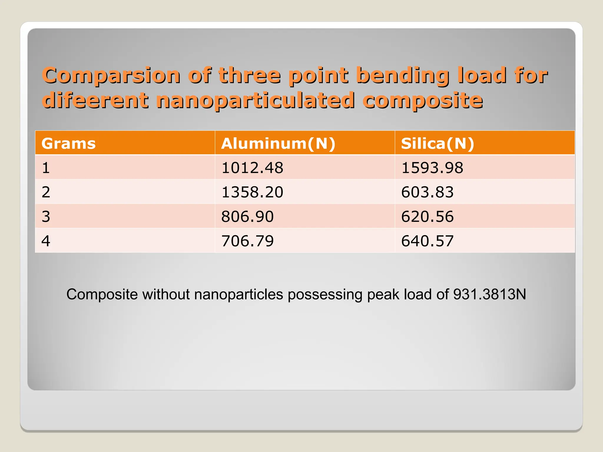
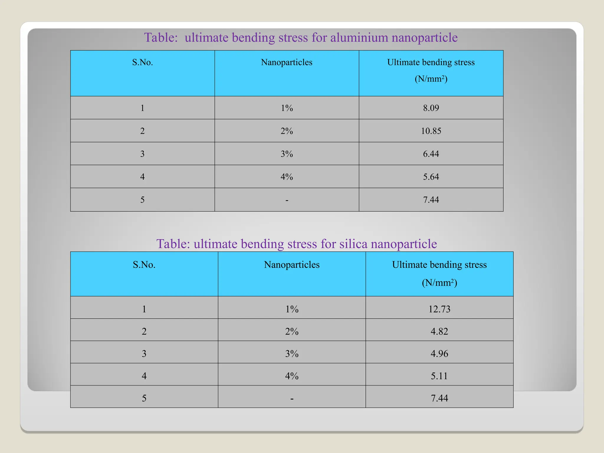
This research focuses on the development of multiscale reinforcement composites using nanoparticles to enhance properties such as tensile strength and flexural rigidity for applications in various industries. Key findings indicate that aluminum and silica nanoparticles significantly improve the mechanical properties of composites, with notable increases in tensile and bending strength. The study establishes a foundation for further exploration of nanoparticle-enhanced composites and their manufacturing processes.