Eagle Composite Hose - Petroleum Hose - Fluid Transfer hose

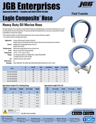
Eagle Composite Hose - Petroleum Hose - Fluid Transfer hose - Heavy Duty Oil Marine Hose. This composite Petroleum Hose is for handling the suction and discharge of gasoline, diesel fuel, paraffin, kerosene, lubricating oils, 100% aromatics, black oils and heavy lubricants and solvents. The petroleum hose assembly is ideal for loading and unloading barges, ocean tankers and bunkering services, and other dockside operations. The composite hose carcass is constructed of multiple layers of polypropylene fabric, film and polyester barrier layers. The cover is abrasion resistant PVC impregnated fabric. It is reinforced with high tensile strength galvanized inner and outer wire. This tough PVC outer cover is resistant to dragging wear, abrasion, UV and ozone. Electrical continuity is achieved by the two wires bonded to the end fitting. This helps dissipate accumulated charge and avoids static flash. The spiral wound high tensile galvanized inner and outer wires provide the strength and flexibility to maintain hose integrity.

Recommended
Recommended
More Related Content
What's hot
What's hot (20)
Similar to Eagle Composite Hose - Petroleum Hose - Fluid Transfer hose
Similar to Eagle Composite Hose - Petroleum Hose - Fluid Transfer hose (20)
More from JGB Enterprises, Inc.
More from JGB Enterprises, Inc. (20)
Recently uploaded
Recently uploaded (20)
Eagle Composite Hose - Petroleum Hose - Fluid Transfer hose
- 1. Fluid Transfer JGB Enterprises Eagle Composite ® Hose Heavy Duty Oil Marine Hose Application: Suction and Discharge of Gasoline, Diesel fuel, Paraffin, Kerosene, Lubricating Oils, 100% aromatics, black oils and heavy lubricants and solvents. Carcass: Multiple layers of polypropylene fabric, film and polyester barrier layers Reinforcement: High tensile strength galvanized inner and outer wire Cover: Abrasion resistant PVC impregnated fabric Temperature: -22°F to +176°F (-30°C to +80°C) Flange: Fix x floating per ANSI B 16.5 CARBON STEEL 150LBS SPECIFICATION (*Complies with USCG 33CFR 154.500) Vic: Standard cut groove carbon steelVic Safety Factor: 4:1 Branding: EAGLE COMPOSITE ® OIL SERVICE S&D CARGO 200PSI MAXWP #Q## USCG 33CFR 154.500 Part # ID MaxWP Burst Bend Radius Weight Max. Length in psi psi in lb/ft ft 006-0642-0010I/0020I 4 200 850 16 3.5 65 006-0962-0010I/0020I 6 200 850 23 7.7 65 006-1280-0010I/0020I 8 200 850 32 12.0 65 006-1600-0010I/0020I 10 200 850 40 16.9 40 006-1920-0010I/0020I 12 200 850 47 19.8 40 Approximate weight of Fix x Floating Flange Hose Size Hose Length Weight Hose Length Weight in ft lbs ft lbs 4 10 70.55 20 99.20 6 10 160.94 20 233.69 8 10 264.56 20 381.40 10 10 363.76 20 507.06 12 10 551.25 20 760.01 Approximate weight ofVic xVic Hose Size Hose Length Weight Hose Length Weight in ft lbs ft lbs 4 10 52.91 20 85.98 6 10 136.69 20 209.44 8 10 227.08 20 343.92 10 10 319.67 20 462.97 12 10 396.43 20 696.16 (Approved by DNV GL / *Complies with USCG 33CFR 154.500) ® JGB ® Headquarters Liverpool, NY 13088 (315) 451-2770 Buffalo Branch Cheektowaga, NY 14225 (716) 684-8224 Southeast Hub Charlotte, NC 28273 (704) 588-9920 St. Louis Branch St. Louis, MO 63123 (314) 487-3144 Williston Branch Williston, ND 58801 (701) 774-2195 Houston Branch Pasadena, TX 77503 (281) 930-7777 Click for directions: Download the JGB® Mobile AppWARNING: Cancer and Reproductive Harm - www.P65Warnings.ca.gov Connect with us: www.jgbhose.com The Eagle Composite ® Hose assembly is recommended for loading and unloading barges, ocean tanker & bunkering services, and is recommended for other doc side operations.The spiral wound high tensile galvanized inner and outer wires provide the strength and flexibility to maintain hose integrity. * All Pre-Made Assemblies are 100% hydrostatically tested, and are received with factory supplied test certificates which are available upon request. ISO 9001:2015 Certified
- 2. HANDLING & MAINTENANCE Traction: Do not use hose in between (FIG. 1). Let it form a small curve (FIG. 2). Torsion: Hose is not manufactured to work in torsion (FIG. 3). During installation it is essential to ensure that the hose is not twisted. Let it follow an ideal lay-line (FIG. 4). Bending Radius: Installation tighter than the minimum bending radius reduces the life of the hose considerably. Moreover it is necessary to avaoid bending close to the end fittings (FIG. 5 & 6). Installation: The hoses must be supported to allow normal movement when must under pressure (dimentionsl variations). Do not rest hose on sharp edges (FIG. 7 & 7B). Take adequate precautions (FIG. 8 & 8B). Do not support hoses with ropes or chains (FIG. 9). Flexible hose supports or polyester slings are recommended. (FIG. 10) Storage: Hose must be stored in a relaxed condition free from tension, compression or other deformation. Contact with objects that could pierce or cut must be avoided. When not in use, hose should be stored in a dark place preferably, avoiding direct sunlight and rain. It must be protected from rodents and insects. When such a risk is probable, appropriate precautions must be taken. Norms and Method of Use: Prior to installation it is necessary to check the characteristics of the hose carefully to ensure that type, diameter and length conform to the required specification. (FIG 12) Moreover a visual check must be carried out to make sure that there are no obstructions, cuts damaged cover or any other evident imperfections (FIG 11). Although the hoses are manufactured to guarantee exceptional resistance to abrasion, it is advisable to move them with care, avoiding knocks, dragging over abrasive surfaces or crushing. Furthermore, hoses must not be pulled violently when twisted or knotted. Maintenance : Even when choice, storage and installation is carried out correctly, regular maintenance is necessary. During regular checks, special attention must be paid to couplings and to the appearance of irregularities which can indicate deterioration of the hose. After use, it is advisable to empty the hoses carefully and if necessary, clean thoroughly. We recommend in any case, that the hoses be checked and tested under pressure once a year. NEVER weld reduction couplings or flanges onto original hose fittings. NEVER close or hold the coupling ferrules in a bench vice as they could be deformed. If necessary, hold the hose itself, closing the vice onto the outside spirals of the hose. FIG 12 FIG 8b FIG 8 FIG 6 FIG 4 FIG 2 FIG 5 FIG 3 FIG 7 FIG 9 FIG 10 FIG 7b FIG 1 FIG 11 The following recommendations are the minimum to which the user must adhere. Eagle Slings 5000lb capacity Available 6”through 12”ID