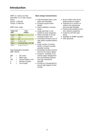
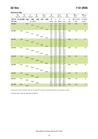
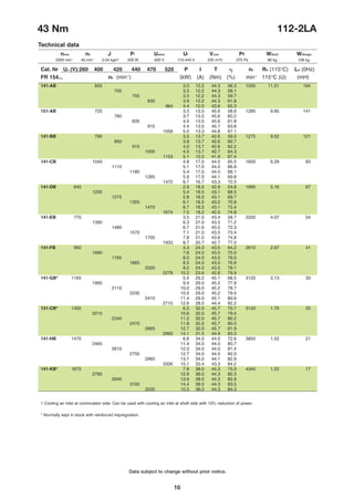
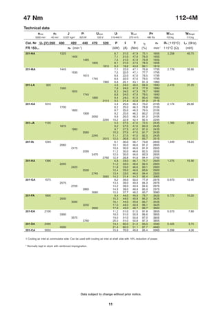
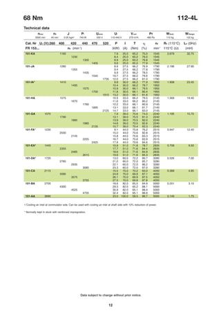
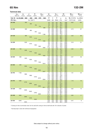
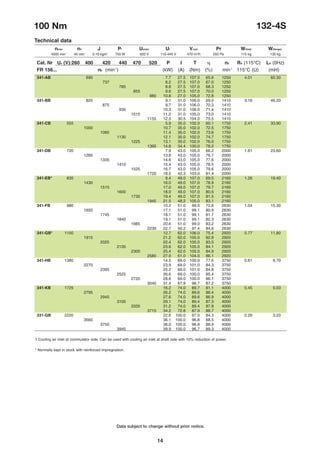
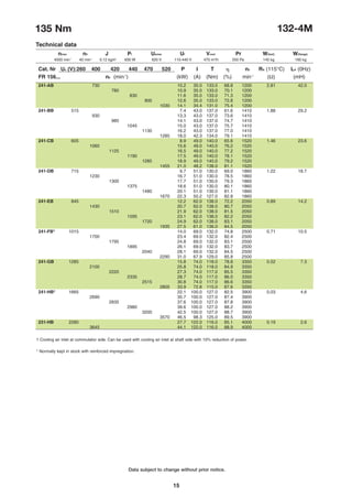
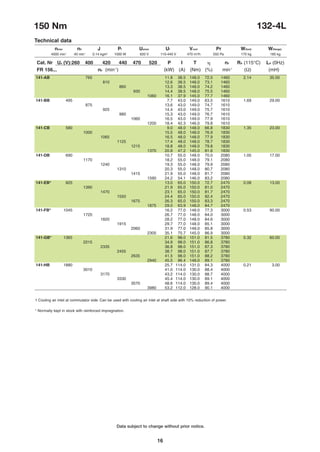
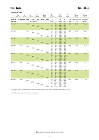
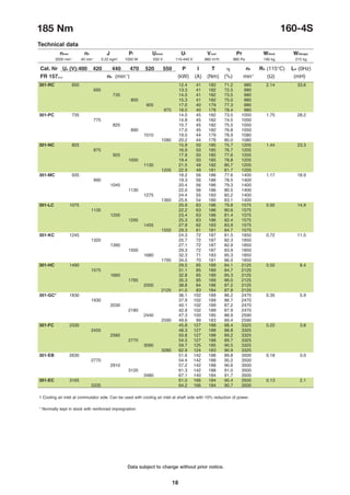
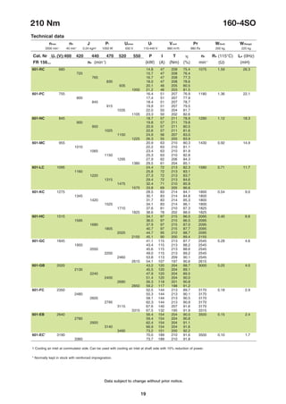
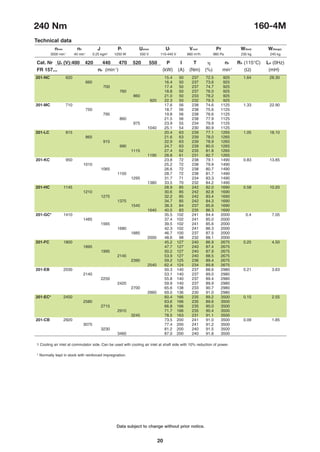
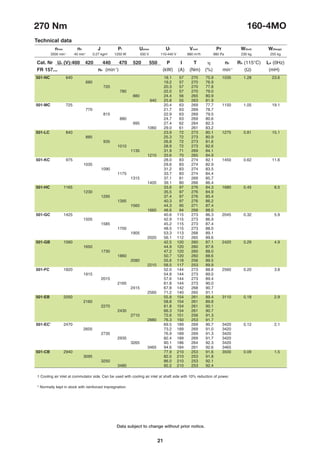
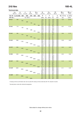
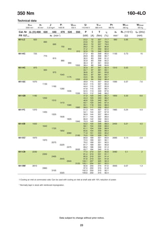
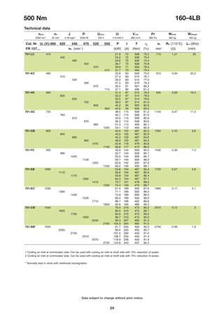
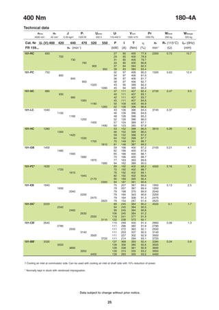
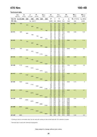
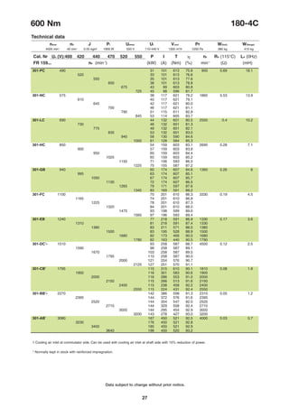
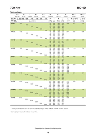
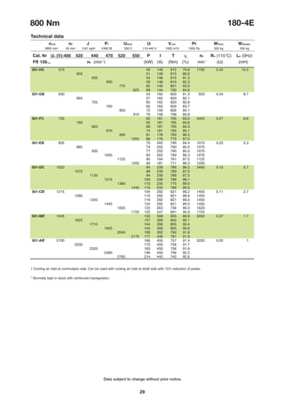
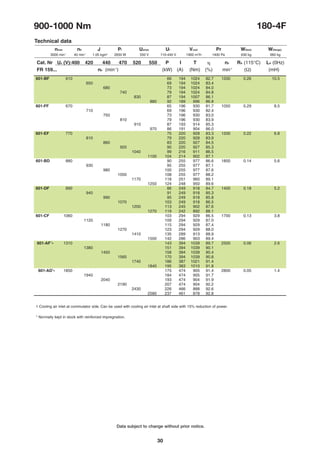
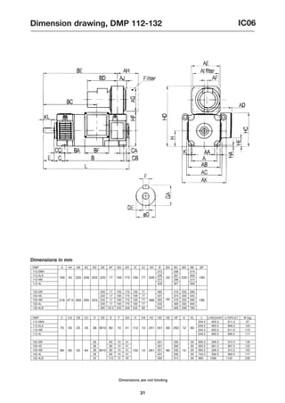
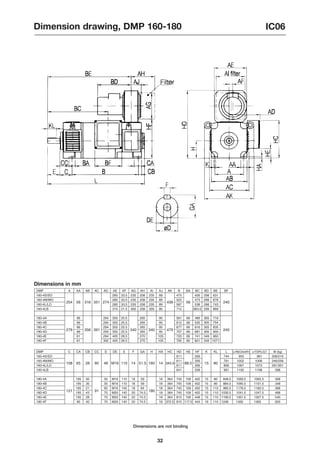
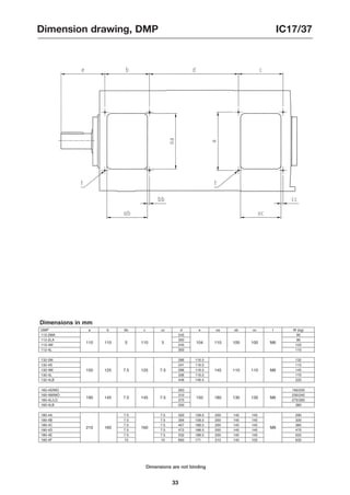
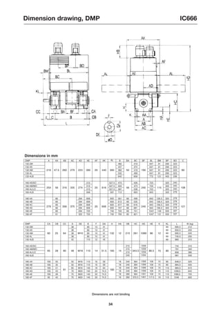
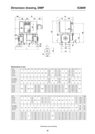
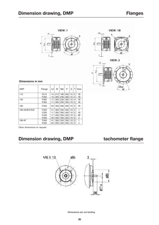
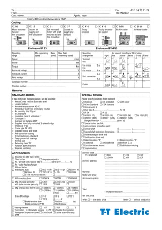
SlideShare a Scribd company logo
DMP catalogue
1-200 kW, 5-1000 Nm
DC Motors
Introduction .................................................................
Options .......................................................................
Application data ..........................................................
Output data ................................................................
Dimension drawings, IC06 .........................................
Dimension drawings, IC17/37 ....................................
Dimension drawings, IC666 .......................................
Dimension drawings, IC86W ......................................
Dimensions, flanges ...................................................
Order form ..................................................................
p. 3
p. 4
p. 5
p. 7
p. 31
p. 33
p. 34
p. 35
p. 36
p. 37
List of contents
Basic design characteristics
Fully laminated stator, main
poles and interpoles.
Compact square frame
design.
Easy installation of acces-
sories.
Large openings in end
shields for easy inspection.
Stator windings of varnish
insulated copper wire.
Laminated armature core of
high grade insulated electro-
plate.
Large number of cooling
ducts in armature provide
excellent cooling.
Scrambled armature lamina-
tions for low torque ripples.
Armature windings of var-
nished copper designed for
low commutating stresses
and high mechanical
strength.
Armature is impregnated to
ensure high degree of heat
transfer.
DMP d.c. motors are fully
laminated, 2 or 4 pole, square
frame.
Output: 1-200 kW
Torque: 5-1000 Nm
DMP motor range:
Type designation example :
DMP 180-4E
DM = DC motor
P = Motor type
180 = Centre height in mm
4 = Number of poles
E = Core length
3
Introduction
Brush holders with spring
loaded pressure fingers.
Prepared for a number of
options and accessories
ensuring high flexibility.
Painting with excellent corro-
sion resistant properties.
Conforms with IEC stan-
dards.
Available as NEMA standard.
CSA approved.
·
·
·
·
·
·
·
·
·
·
·
·
·
·
·
·
Frame size
DMP
112-2
112-4
132-2
132-4
160-4
180-4
Core
lengths
MA, LA
M, L
M
S, M, L, LB
S, SO, M, MO, L, LO, LB
A, B, C, D, E, F
Frame size DMP 112-2 112-4 132-2 132-4 160 180
Cooling forms
IC06 (IP23) Force ventilated
IC17 (IP23) Single pipe ventilated
IC37 (IP54) Double pipe ventilated
IC410 (IP54) Totally enclosed
IC416 (IP54) Totally enclosed, fan cooled
IC666 (IP54) Air-air cooled
IC86W (IP54) Air-water cooled
Other cooling forms available
Protection
IP55
Mounting forms
IM1001 Horizontal foot
IM1002 Horizontal foot, two shaft ends
IM2001 Horizontal foot and flange
IM2011 Vertical foot and flange
Other mounting forms available
Modifications and accessories
Compound winding
Pressure switch
Temperature sensor, interpole
Temperature sensor, field winding
Bearing sensor
Grounding brush
Heating element
Brush wear sensor
Special shaft
Roller bearing d-end
Shaft seal, d-end
Special balance Class ‘R’
Special paint (RAL colour)
Special corrosion protection
Transparent inspection cover
Brake
Gearbox
Tachos with coupling
REO 444R1 (60v/1000min-1
)
TDP 0.2 LT-4 (60v/1000min-1
)
Others available
Pulse generators
POG 9 D (1-1250 ppr)
HG650 or DG60L (1024 ppr)
Others available
4
Options
o
o
o
o
o
o
o
o
o
o
o
o
o
o
o
o
o
o
o
o
o
o
o
o
o
o
o
o
o
o
o
o
o
o
o
o
o
o
o
o
o
o
o
o
o
o
o
o
o
o
o
o
o
o
o
o
o
o
o
o
o
o
o
o
o
o
o
o
o
o
o
o
o
o
o
o
o
o
o
o
o
o
o
o
o
o
o
o
o
o
o
o
o
o
o
o
o
o
o
o
o
o
o
o
o
o
o
o
o
o
o
o
o
o
o
o
o
o
o
o
o
o
o
o
o
o
o
o
o
o
o
o
o
o
o
o
o
o
o
o
o
o
o
o
o
o
o
o
o
o
o
o
o
o
o
o
o
o
o
o
o
o
o
o
o
o
o
o
o
o
o
o
o
o
o
o
o
o
o
o
o
o
o
o
o
o
o
o
o
o
o
o
o
o
o
o
o
o
o
o
o
o
5
Application data
Standards
IEC 34 - IEC 72 etc.
Insulation
Class H
Temperature rise
Class F
Balance
IEC 34-14 grade 'N' standard.
Grade 'R' on request.
Overload capacity
180% xFLC for
15 sec. every 5 minutes
30 sec. every 30 minutes
Terminal box
Standard position: On right hand
side (facing D-end).
Mounting of terminal box on top
or left hand side on request.
DMP motors are delivered with
a large terminal box IP55 includ-
ing knockout openings:
DMP 112 – 132
2 x Ø 28.5 (PG 21)
2 x Ø 20.5 (PG 13.5)
Cable entry from Drive end.
DMP 160 – 180
2 x Ø 55 (PG 42)
4 x Ø 28.5 (PG 21)
Cable entry from above or
below.
Blower position
Standard: On top of the motor at
the non-drive end.
Other positions on request.
Blower is supplied without filter
as standard.
Filter on request.
Bearings
Grease lubricated ball bearings
as standard.
For belt drive please contact our
sales offices.
Heat exchangers
Air/water (IC86W):
Air/water exchangers are espe-
cially recommended for polluted
environment.
Standard is for clean water.
For corrosive water on request.
Position on top of the motor as
standard. Fan motor at N-end.
Water connection flanges at
right hand side (facing D-end).
Max. water pressure 10 PSI
Max. inlet water temperature
250
C. A water temperature rise
of 8-100
C must be expected.
For motors with low loads or a
low incoming water temperature,
a temperature regulator is
recommended to avoid conden-
sation in the cooling air circuit
and to minimize water consump-
tion.
A constant speed fan circulates
the internal cooling air. A polya-
mide filter is provided for carbon
dust.
Air/air (IC666):
Air/air heat exchangers are
recommended where water is
not available for cooling purpo-
ses.
The output of a motor with
air/air exchanger will be approxi-
mately 20% lower compared to
cooling forms IC06/17/37/86W.
Position: On top of the motor as
standard.
Two constant speed fans at top
of the heat exchanger to provide
air circulation for the outer and
inner circuits.
Detailed heat exchanger information on request.
6
Fan blower motor data
DMP Unet , fnet (Y) IY (A) Unet, fnet (∆) I∆ (A) Pfan (kW) Wfan (kg)
112 3x380-420 V. 50 Hz 0.70 3x220-240 V. 50 Hz 1.20 0.25 7
132-2M 3x440-480 V. 60 Hz 0.70 3x250-280 V. 60 Hz 1.20 0.30
132-4S/M/L 3x500 V. 50 Hz 0.60 - - 0.25
132-4LB 3x380-420 V. 50 Hz 2.10 3x220-240 V. 50 Hz 3.60 0.75 16
160-4S/M/L 3x440-480 V. 60 Hz 2.00 3x250-280 V. 60 Hz 3.50 0.90
3x500 V. 50 Hz 1.40 - - 0.75
160-4LB 3x380-420 V. 50 Hz 2.90 3x220-240 V. 50 Hz 5.00 1.30 18
3x440-480 V. 60 Hz 2.80 3x250-280 V. 60 Hz 5.00 1.50
3x500 V. 50 Hz 2.30 - - 1.30
180-4A/B/C/D 3x380-420 V. 50 Hz 3.00 3x220-240 V. 50 Hz 5.20 1.50 18
3x440-480 V. 60 Hz 2.90 3x250-280 V. 60 Hz 5.00 1.75
3x500 V. 50 Hz 2.70 - - 1.50
180-4E/F 3x380-420 V. 50 Hz 5.80 3x220-240 V. 50 Hz 10.0 2.70 20
3x440-480 V. 60 Hz 5.80 3x250-280 V. 60 Hz 10.0 3.00
3x500 V. 50 Hz 4.60 - - 2.70
Unet , fnet (Y) Supply voltage, frequency Y
IY Current Y
Pfan Power
Unet , fnet (∆) Supply voltage, frequency ∆
I∆ Current ∆
Wfan Total fan weight
Bearings
Drive end Non-drive end
DMP Ball bearing Roller bearing
112 6308-C3 NU 308 ECP 6208-2RS 1-HT-C3
132 6309-C3 NU 309 ECP 6307-2RS 1-HT-C3
160 6310-C3 NU 310 ECP 6309-2RS 1-HT-C3
180-4A/B/C/D/E 6215-C3 NU 2215-ECP 6312-2RS1-HT-C3
180-4F 6315-C3 NU 315 ECP 6312-2RS1-HT-C3
Application data
7
Select motor frame size against
voltage, output and speed. For
intermediate output, take the
nearest higher output listed
under the next frame size. For
intermediate speed take the
next lower speed listed within
the output required. The output
lists are based on:
• Cooling forms
IC06/IC17/IC37/IC86W.
• The armature circuit resis-
tance listed is for duty
warm condition.
• The inductance listed is for
the armature circuit.
• Motor supply from 3-phase
fully controlled thyristor.
Constant power/constant
torque
The full field or base speed and
maximum speed through field
control with constant output is
listed for each winding.
Armature voltage: For -10% the
output and speed are proportio-
nal to the voltage.
For higher shunt field ranges,
please refer to sales offices.
With a combination of armature
voltage/shunt control greater
constant power ranges can be
obtained.
Duty cycles
Ratings: All outputs are duty
type S 1 and motors are fed
from a 3-phase fully controlled
thyristor where the form factor
is 1.05.
Field windings
All motors in the output lists
have separate excitation, the
field being shunt wound.
Compound winding can be
supplied on request.
Motors with compound winding
may have nominal data which
differ from those shown in the
output lists.
Armature voltage
For other armature voltages,
please contact our sales offices.
Ambient temperature and
altitude
Outputs in this catalogue are
based on max. 400
C ambient
temperature and motor located
at max. 1000 metres above sea
level.
If ambient temperature and/or
altitude is higher, contact our
sales office.
NEMA output data
NEMA catalogue available on
request.
Stock motors
Motors indicated with the sign✱
in the output data lists are
available from stock and can be
delivered promptly.
The stock motors are available
according to following specifica-
tion. Motor fan, standard tacho-
generator and coupling can be
fitted on request.
• IM 1001, IP 23, IC 17, desig-
ned for cooling air inlet at
either D or N-end (when
possible, cooling air inlet
should always be at the D-
end of DMP motors).
• Cylindrical roller bearing on
D-end.
• Terminal box on right hand
side (facing D-end).
• Balanced with half key.
• Thermostats NC.
• PTC thermistors.
• Name plate and documents
in English.
• Rating data as standard
motors but field weakening
is only allowed up to 25 %
overspeed for stock
motors.
• Stock motors have a paral-
lel /serial connection sui-
table for an excitation volta-
ge of 170-180-190/340-360-
380 V.
• Stock motors have reinfor-
ced impregnation.
Output data
8
Technical data
nmax n0 J Pf Uamax Uf Vcool Pr W(foot) W(flange)
nmax Max mechanical speed
n0 Min speed at constant torque
J Moment of inertia
Pf Excitation power
Uamax Max rated voltage
Uf Excitation voltage
Vcool Cooling air flow
Pr Static pressure drop (IC17, IC37)
W(foot) Weight: foot mounting *
W(flange) Weight: flange mounting *
*excl. accessories
Cat. Nr Ua (V): 400 420 440 470 520 550 P I T h n2 RA (115°C) LA (0Hz)
FR 157… nb (min-1
) (kW) (A) (Nm) (%) min-1
(Ω) (mH)
nb Base speed
Ua Armature voltage
P Mechanical power
I Armature current
T Torque
h Efficiency IEC
n2 Max electrical speed
RA Armature resistance
LA Armature inductance


Data subject to change without prior notice.
Output data
9
30 Nm
Data subject to change without prior notice.
112-2MA
Technical data
nmax n0 J Pf Uamax Uf Vcool Pr W(foot) W(flange)
241-AB 1000 3.2 12.2 31.0 61.1 1605 9.84 120
1075 3.5 12.2 31.0 62.8
1145 3.7 12.2 31.0 64.1
1255 4.1 12.2 31.0 66.0
1440 4.6 12.0 30.4 68.9
241-BB 645 2.0 13.5 29.1 50.3 1960 7.78 88
1235 3.8 13.5 29.3 65.0
1315 4.0 13.5 29.3 66.2
1400 4.3 13.5 29.3 67.5
1525 4.7 13.5 29.3 69.2
1745 5.3 13.3 28.8 71.8
241-CB 860 2.8 17.0 30.8 57.4 2480 5.14 61
1570 5.1 17.0 30.8 70.0
1670 5.4 17.0 30.8 71.2
1770 5.7 17.0 30.8 72.2
1920 6.2 17.0 30.8 73.6
2180 6.9 16.7 30.3 75.8
251-CB 1010 3.2 18.5 30.2 61.1 3060 4.21 49
1795 5.7 18.5 30.2 61.1
1905 6.0 18.5 30.2 73.5
2015 6.4 18.5 30.2 74.5
2185 6.9 18.5 30.2 75.7
2475 7.7 18.2 29.7 77.7
241-DB 1185 3.8 21.0 30.4 64.4 3250 3.33 39
2070 6.6 21.0 30.4 74.8
2195 7.0 21.0 30.4 75.7
2320 7.4 21.0 30.4 76.5
2510 8.0 21.0 30.4 77.7
2832 8.9 20.7 29.9 79.4
241-EB* 1445 4.5 23.7 30.0 69.1 3835 2.42 30
2450 7.7 23.7 30.0 77.9
2595 8.2 23.7 30.0 78.7
2740 8.6 23.7 30.0 79.4
2955 9.3 23.7 30.0 80.4
3325 10.3 23.3 29.5 81.8
231-EB 1740 5.8 29.0 31.6 72.3 3595 1.75 30
2920 9.6 29.0 31.5 80.1
3085 10.2 29.0 31.5 80.8
3255 10.7 29.0 31.5 81.4
231-FB 2175 7.0 34.0 30.8 75.7 3835 1.25 15
3590 11.5 34.0 30.7 82.3
3790 12.2 34.0 30.7 82.9
3995 12.8 34.0 30.7 83.4
231-GB1
2820 8.7 41.0 29.6 79.0 5000 0.85 10
4590 14.2 41.0 29.6 84.3
Cat. Nr Ua (V):260 400 420 440 470 520 P I T h n2 RA (115°C) LA (0Hz)
FR 154... nb (min-1
) (kW) (A) (Nm) (%) min-1
(Ω) (mH)
5000 min-1
40 min-1
0.03 kgm2
420 W 620 V 110-440 V 235 m3
/h 375 Pa 90 kg 102 kg

1 Cooling air inlet at commutator side. Can be used with cooling air inlet at shaft side with 10% reduction of power.
* Normally kept in stock with reinforced impregnation.
Data subject to change without prior notice.
10
43 Nm 112-2LA
Technical data
nmax n0 J Pf Uamax Uf Vcool Pr W(foot) W(flange)
141-AB 655 3.0 12.2 44.3 56.3 1055 11.51 164
705 3.3 12.2 44.3 58.1
755 3.5 12.2 44.3 59.7
830 3.9 12.2 44.3 61.8
964 4.4 12.0 43.6 65.3
151-AB 725 3.5 13.5 45.6 58.6 1280 9.85 141
780 3.7 13.5 45.6 60.2
835 4.0 13.5 45.6 61.8
915 4.4 13.5 45.7 63.8
1058 5.0 13.3 44.8 67.1
141-BB 790 3.5 13.7 42.6 59.0 1275 9.52 121
850 3.8 13.7 42.6 60.7
910 4.0 13.7 42.6 62.2
1000 4.5 13.7 42.7 64.3
1153 5.1 13.5 41.9 67.4
141-CB 1040 4.8 17.0 44.0 65.5 1650 6.29 83
1110 5.1 17.0 44.0 66.8
1180 5.4 17.0 44.0 68.1
1285 5.9 17.0 44.1 69.8
1472 6.7 16.7 43.3 72.5
141-DB 645 2.9 18.5 42.9 54.8 1895 5.16 67
1200 5.4 18.5 43.1 68.5
1275 5.8 18.5 43.1 69.7
1355 6.1 18.5 43.2 70.8
1470 6.7 18.5 43.1 72.4
1674 7.5 18.2 42.5 74.8
141-EB 770 3.5 21.0 43.4 58.7 2200 4.07 54
1390 6.3 21.0 43.5 71.2
1480 6.7 21.0 43.5 72.3
1570 7.1 21.0 43.5 73.4
1705 7.8 21.0 43.6 74.8
1933 8.7 20.7 42.7 77.0
141-FB 950 4.3 24.0 43.5 64.2 2610 2.97 41
1660 7.6 24.0 43.5 75.0
1765 8.0 24.0 43.5 76.0
1865 8.5 24.0 43.5 76.9
2020 9.2 24.0 43.5 78.1
2278 10.2 23.6 42.8 79.9
141-GB* 1165 5.5 29.2 45.1 68.5 3120 2.13 30
1995 9.4 29.0 45.2 77.9
2110 10.0 29.0 45.2 78.7
2230 10.5 29.0 45.2 79.5
2410 11.4 29.0 45.1 80.6
2710 12.6 28.5 44.4 82.2
131-CB* 1305 6.2 32.0 45.7 70.7 3120 1.76 25
2210 10.6 32.0 45.7 79.4
2340 11.2 32.0 45.7 80.2
2470 11.8 32.0 45.7 80.0
2665 12.7 32.0 45.7 81.9
2993 14.1 31.5 44.9 83.3
141-HB 1470 6.8 34.0 44.0 72.6 3850 1.52 21
2465 11.4 34.0 44.0 80.7
2610 12.0 34.0 44.0 81.4
2750 12.7 34.0 44.0 82.0
2965 13.7 34.0 44.1 82.9
3326 15.1 33.4 43.3 84.2
141-KB* 1675 7.8 38.0 44.3 75.0 4340 1.22 17
2785 12.9 38.0 44.3 82.3
2940 13.6 38.0 44.3 82.9
3100 14.4 38.0 44.3 83.5
3335 15.5 38.0 44.3 84.3
Cat. Nr Ua (V):260 400 420 440 470 520 P I T h n2 RA (115°C) LA (0Hz)
FR 154... nb (min-1
) (kW) (A) (Nm) (%) min-1
115°C (Ω) (mH)
5000 min-1
40 min-1
0.04 kgm2
500 W 620 V 110-440 V 235 m3
/h 375 Pa 96 kg 108 kg

1 Cooling air inlet at commutator side. Can be used with cooling air inlet at shaft side with 10% reduction of power.
* Normally kept in stock with reinforced impregnation.
Data subject to change without prior notice.
11
47 Nm 112-4M
Technical data
nmax n0 J Pf Uamax Uf Vcool Pr W(foot) W(flange)
201-NA 1325 6.7 21.0 47.9 75.1 1655 3.258 40.75
1405 7.1 21.0 47.9 76.0 1655
1485 7.5 21.0 47.9 76.9 1655
1605 8.1 21.0 47.9 78.0 1655
1810 8.3 19.2 43.8 80.1 1810
201-MA 1445 7.1 22.0 47.1 76.8 1795 2.776 35.80
1530 7.5 22.0 47.1 77.7 1795
1615 8.6 22.0 47.0 78.5 1795
1745 8.6 22.0 47.0 79.5 1795
1960 8.8 20.1 43.1 81.3 1960
201-LA 920 4.6 24.0 48.0 68.9 1890 2.416 31.20
1565 7.8 24.0 47.9 77.9 1890
1655 8.3 24.0 47.9 78.7 1890
1745 8.8 24.0 47.9 79.5 1890
1890 9.4 24.0 47.9 80.4 1890
2115 9.5 21.4 42.8 81.9 2115
201-KA 1010 4.9 25.0 46.3 70.2 2105 2.174 26.90
1700 8.2 25.0 46.3 78.8 2105
1800 8.7 25.0 46.3 79.5 2105
1900 9.2 25.0 46.3 80.2 2105
2050 9.9 25.0 46.3 81.2 2105
2295 10.2 22.9 42.4 82.5 2295
201-JA 1120 5.5 27.5 47.0 72.5 2435 1.783 22.90
1870 9.2 27.5 47.0 80.3 2435
1980 9.7 27.5 47.0 81.0 2435
2085 10.3 27.5 47.0 81.7 2435
2245 11.1 27.5 47.0 82.5 2435
2515 12.0 26.6 45.5 83.7 2515
201-IA 1240 6.1 30.0 46.7 73.8 2655 1.549 19.25
2060 10.1 30.0 46.6 81.2 2655
2175 10.6 30.0 46.6 81.9 2655
2295 11.2 30.0 46.6 82.5 2655
2470 12.0 30.0 46.6 83.3 2655
2760 12.9 28.8 44.8 84.4 2760
201-HA 1390 6.8 33.0 46.7 75.7 2920 1.275 15.90
2295 11.2 33.0 46.6 82.5 2920
2420 11.8 33.0 46.6 83.1 2920
2550 12.4 33.0 46.6 83.6 2920
2745 13.4 33.0 46.6 84.4 2920
3065 14.2 31.4 44.3 85.4 3065
201-GA 1575 8.2 39.0 50.0 77.9 2975 0.973 12.90
2575 13.5 39.0 49.9 84.0 2975
2720 14.2 39.0 49.9 84.6 2975
2860 14.9 39.0 49.9 85.0 2975
3080 15.5 37.7 48.2 85.7 3080
201-FA 1800 9.4 44.0 49.9 79.7 3425 0.772 10.20
2930 15.3 44.0 49.8 85.2 3425
3090 16.1 44.0 49.8 85.7 3425
3250 17.0 44.0 49.8 86.1 3425
3500 17.8 43.0 48.7 86.7 3500
201-EA 2100 11.2 51.0 51.0 81.8 3855 0.573 7.80
3390 18.0 51.0 50.8 86.6 3855
3575 19.0 51.0 50.8 87.0 3855
3760 20.0 51.0 50.8 87.3 3855
201-DA 2495 13.4 60.0 51.3 83.5 4460 0.425 5.75
4000 21.4 60.0 51.1 87.7 4460
201-CA 3055 15.9 70.0 49.8 85.4 5000 0.298 4.00
Cat. Nr Ua (V):260 400 420 440 470 520 P I T h n2 RA (115°C) LA (0Hz)
FR 153... nb (min-1
) (kW) (A) (Nm) (%) min-1
115°C (Ω) (mH)
5000 min-1
40 min-1
0.037 kgm2
625 W 550 V 110-440 V 270 m3
/h 480 Pa 103 kg 115 kg

1 Cooling air inlet at commutator side. Can be used with cooling air inlet at shaft side with 10% reduction of power.
* Normally kept in stock with reinforced impregnation.
12
Data subject to change without prior notice.
68 Nm 112-4L
Technical data
nmax n0 J Pf Uamax Uf Vcool Pr W(foot) W(flange)
101-KA 1160 7.9 25.0 65.2 75.0 1545 2.679 32.75
1230 8.4 25.0 65.2 76.0 1545
1300 8.9 25.0 65.2 76.8 1545
1405 9.6 25.0 65.2 77.9 1545
101-JA 1280 8.9 27.5 66.2 76.9 1790 2.196 27.90
1355 9.4 27.5 66.2 77.8 1790
1435 9.9 27.5 66.2 78.5 1790
1545 10.7 27.5 66.2 79.6 1790
1735 12.0 27.5 66.2 81.0 1790
101-IA* 1410 9.8 30.0 66.2 77.9 1950 1.908 23.45
1495 10.4 30.0 66.2 78.7 1950
1575 10.9 30.0 66.1 79.5 1950
1700 11.8 30.0 66.1 80.4 1950
1910 13.2 30.0 66.1 81.8 1950
101-HA 1575 10.9 33.0 66.2 79.5 2145 1.569 19.40
1670 11.6 33.0 66.2 80.2 2145
1760 12.2 33.0 66.1 80.9 2145
1895 13.1 33.0 66.1 81.7 2145
2125 14.7 33.0 66.1 83.0 2145
101-GA 1070 7.9 39.0 70.6 74.0 2240 1.195 15.70
1790 13.1 39.0 70.5 81.3 2240
1880 13.9 39.0 70.5 82.0 2240
1980 14.6 39.0 70.5 82.6 2240
2135 15.7 39.0 70.4 83.3 2240
101-FA* 1230 9.1 44.0 70.8 76.2 2515 0.947 12.40
2030 15.0 44.0 70.6 82.8 2515
2145 15.8 44.0 70.6 83.3 2515
2255 16.7 44.0 70.6 83.9 2515
2425 17.9 44.0 70.6 84.6 2515
101-EA* 1445 10.9 51.0 71.8 78.7 2835 0.708 9.50
2355 17.7 51.0 71.6 84.4 2835
2485 18.6 51.0 71.6 84.9 2835
2615 19.6 51.0 71.6 85.3 2835
101-DA* 1720 13.0 60.0 72.2 80.7 3280 0.526 7.00
2785 21.0 60.0 72.0 85.7 3280
2935 22.1 60.0 72.0 86.2 3280
3085 23.3 60.0 72.0 87.0 3280
101-CA 2115 15.5 70.0 70.2 83.0 4050 0.368 4.85
3390 24.8 70.0 69.9 87.1 4050
3575 26.1 70.0 69.9 87.5 4050
3755 27.5 70.0 69.8 87.8 4050
101-BA 2705 18.6 82.0 65.5 84.9 5000 0.251 3.10
4300 29.3 82.0 65.2 88.1 5000
4525 30.9 82.0 65.1 88.4 5000
4755 32.4 82.0 65.1 88.6 5000
101-AA 3690 23.0 100.0 59.5 86.7 5000 0.149 1.75
Cat. Nr Ua (V):260 400 420 440 470 520 P I T h n2 RA (115°C) LA (0Hz)
FR 153... nb (min-1
) (kW) (A) (Nm) (%) min-1
115°C (Ω) (mH)
5000 min-1
40 min-1
0.05 kgm2
740 W 550 V 110-440 V 270 m3
/h 480 Pa 110 kg 122 kg
1 Cooling air inlet at commutator side. Can be used with cooling air inlet at shaft side with 10% reduction of power.
* Normally kept in stock with reinforced impregnation.
13
Data subject to change without prior notice.
65 Nm 132-2M
Technical data
nmax n0 J Pf Uamax Uf Vcool Pr W(foot) W(flange)
241-AB 605 4.0 16.4 63.1 56.1 1460 8.93 132
650 4.3 16.4 63.1 57.9 1480
700 4.6 16.4 63.1 59.5 1480
770 5.1 16.4 63.4 61.7 1480
898 5.8 16.1 62.1 65.2 1480
241-BB 830 5.6 20.5 64.3 63.7 1725 5.73 87
885 6.0 20.5 64.3 65.1 1725
945 6.4 20.5 64.3 66.5 1725
1035 7.0 20.5 64.3 68.3 1725
1186 7.9 20.2 63.3 71.2 1725
241-CB 980 6.6 23.3 64.6 67.0 1950 4.50 68
1045 7.1 23.3 64.6 68.3 1950
1110 7.5 23.3 64.6 69.5 1950
1210 8.2 23.3 64.6 71.2 1950
1383 9.2 22.9 63.5 73.8 1950
241-DB 1200 8.3 27.5 66.1 71.7 2200 3.18 51
1275 8.8 27.5 66.1 72.8 2200
1350 9.3 27.5 66.1 73.9 2200
1465 10.1 27.5 66.1 75.3 2200
1664 11.3 27.0 65.0 77.5 2200
231-AB 745 5.3 30.5 67.6 62.2 1860 2.60 43
1330 9.4 30.5 67.7 73.8 1860
1415 10.0 30.5 67.7 74.9 1860
1495 10.6 30.5 67.7 75.8 1860
1620 11.5 30.5 67.7 77.1 1860
1835 12.8 30.0 66.5 79.0 1860
251-EB 830 5.6 32.0 64.9 63.6 2650 2.37 36
1465 10.0 32.0 65.0 74.8 2650
1555 10.6 32.0 65.0 75.8 2650
1650 11.2 32.0 65.0 76.7 2650
1785 12.2 32.0 65.1 77.9 2650
2019 13.5 31.5 63.9 79.9 2650
241-EB 945 6.6 36.0 66.5 66.5 2840 1.93 30
1650 11.5 36.0 66.4 76.7 2840
1750 12.2 36.0 66.4 77.7 2840
1850 12.9 36.0 66.4 78.5 2840
2000 13.9 36.0 66.4 79.6 2840
2257 15.4 35.4 65.3 81.4 2840
251-FB 1100 7.7 40.0 66.5 70.1 3160 1.51 24
1880 13.1 40.0 66.5 79.1 3160
1990 13.9 40.0 66.5 79.9 3160
2105 14.6 40.0 66.5 80.7 3160
2270 15.8 40.0 66.5 81.7 3160
2554 17.5 39.3 65.3 83.2 3160
241-FB 1280 9.1 46.0 68.0 73.0 3480 1.16 19
2155 15.4 46.0 68.1 81.1 3480
2280 16.3 46.0 68.1 81.8 3480
2405 17.1 46.0 68.1 82.5 3480
2595 18.5 46.0 68.1 83.3 3480
2911 20.4 45.2 66.9 84.7 3480
241-GB 1505 10.6 52.0 67.3 75.4 4000 0.92 15
2500 17.6 52.0 67.3 82.7 4000
2645 18.7 52.0 67.3 83.3 4000
2790 19.7 52.0 67.3 83.9 4000
3000 21.2 52.0 67.4 84.7 4000
231-DB 1820 12.7 60.0 66.9 78.7 4000 0.65 11
2990 20.8 60.0 66.6 84.9 4000
3155 22.0 60.0 66.6 85.4 4000
3320 23.2 60.0 66.6 85.9 4000
231-EB 2240 15.6 72.0 66.5 81.0 4000 0.47 8
3640 25.3 72.0 66.5 86.3 4000
Cat. Nr Ua (V):260 400 420 440 470 520 P I T h n2 RA (115°C) LA (0Hz)
FR 154... nb (min-1
) (kW) (A) (Nm) (%) min-1
115°C (Ω) (mH)
5000 min-1
40 min-1
0.09 kgm2
550 W 620 V 110-440 V 435 m3
/h 400 Pa 132 kg 147 kg
1 Cooling air inlet at commutator side. Can be used with cooling air inlet at shaft side with 10% reduction of power.
* Normally kept in stock with reinforced impregnation.
Data subject to change without prior notice.
14
100 Nm 132-4S
Technical data
nmax n0 J Pf Uamax Uf Vcool Pr W(foot) W(flange)
341-AB 690 7.7 27.5 107.0 65.6 1250 4.01 60.30
737 8.2 27.5 107.0 67.0 1250
785 8.8 27.5 107.0 68.3 1250
855 9.6 27.5 107.0 70.0 1250
980 10.8 27.0 105.0 72.8 1250
341-BB 820 9.1 31.0 106.0 69.0 1410 3.16 46.20
875 9.7 31.0 106.0 70.3 1410
930 10.3 31.0 106.0 71.4 1410
1015 11.2 31.0 105.0 73.0 1410
1155 12.5 30.5 104.0 75.5 1410
341-CB 555 5.9 35.0 102.0 60.1 1750 2.41 33.90
1000 10.7 35.0 102.0 72.5 1750
1065 11.4 35.0 102.0 73.6 1750
1130 12.1 35.0 102.0 74.7 1750
1225 13.1 35.0 102.0 76.0 1750
1390 14.6 34.4 100.0 78.2 1750
341-DB 720 7.9 43.0 105.0 66.2 2000 1.61 23.60
1260 13.8 43.0 105.0 76.7 2000
1335 14.6 43.0 105.0 77.6 2000
1410 15.4 43.0 105.0 78.5 2000
1525 16.7 43.0 105.0 79.6 2000
1720 18.5 42.3 103.0 81.4 2000
341-EB* 835 9.4 49.0 107.0 69.5 2160 1.26 19.40
1430 16.0 49.0 107.0 78.9 2160
1515 17.0 49.0 107.0 79.7 2160
1600 18.0 49.0 107.0 80.5 2160
1730 19.4 49.0 107.0 81.5 2160
1945 21.5 48.2 105.0 83.1 2160
341-FB 980 10.2 51.0 99.0 72.6 2630 1.04 15.30
1650 17.1 51.0 99.1 80.9 2630
1745 18.1 51.0 99.1 81.7 2630
1840 19.1 51.0 99.1 82.3 2630
1985 20.6 51.0 99.0 83.2 2630
2230 22.7 50.2 97.4 84.6 2630
341-GB* 1150 12.7 62.0 106.0 75.4 2920 0.77 11.80
1915 21.2 62.0 105.0 82.8 2920
2025 22.4 62.0 105.0 83.5 2920
2135 23.6 62.0 105.0 84.1 2920
2300 25.4 62.0 105.0 84.9 2920
2580 27.9 61.0 104.0 86.1 2920
341-HB 1380 14.5 69.0 100.0 77.6 3750 0.61 8.70
2270 23.9 69.0 101.0 84.3 3750
2395 25.2 69.0 101.0 84.8 3750
2525 26.6 69.0 100.0 85.4 3750
2720 28.6 69.0 100.0 86.1 3750
3040 31.4 67.9 98.7 87.2 3750
341-KB 1725 16.2 74.0 89.7 81.1 4000 0.45 5.03
2795 26.2 74.0 89.6 86.4 4000
2945 27.6 74.0 89.6 86.9 4000
3100 29.1 74.0 89.4 87.3 4000
3335 31.2 74.0 89.4 87.8 4000
3715 34.2 72.8 87.9 88.7 4000
331-GB 2220 22.6 100.0 97.0 84.3 4000 0.26 3.20
3560 36.1 100.0 96.8 88.5 4000
3750 38.0 100.0 96.8 88.9 4000
3945 39.9 100.0 96.7 89.3 4000
Cat. Nr Ua (V):260 400 420 440 470 520 P I T h n2 RA (115°C) LA (0Hz)
FR 156... nb (min-1
) (kW) (A) (Nm) (%) min-1
115°C (Ω) (mH)
4000 min-1
40 min-1
0.10 kgm2
750 W 620 V 110-440 V 470 m3
/h 550 Pa 115 kg 130 kg
1 Cooling air inlet at commutator side. Can be used with cooling air inlet at shaft side with 10% reduction of power.
* Normally kept in stock with reinforced impregnation.
15
Data subject to change without prior notice.
135 Nm 132-4M
Technical data
nmax n0 J Pf Uamax Uf Vcool Pr W(foot) W(flange)
241-AB 730 10.2 35.0 133.0 68.8 1200 2.81 42.0
780 10.9 35.0 133.0 70.1 1200
830 11.6 35.0 133.0 71.3 1200
900 12.6 35.0 133.0 72.8 1200
1030 14.1 34.4 131.0 75.4 1200
241-BB 515 7.4 43.0 137.0 61.6 1410 1.88 29.2
930 13.3 43.0 137.0 73.6 1410
985 14.1 43.0 137.0 74.7 1410
1045 15.0 43.0 137.0 75.7 1410
1130 16.2 43.0 137.0 77.0 1410
1285 18.0 42.3 134.0 79.1 1410
241-CB 605 8.9 49.0 140.0 65.6 1520 1.46 23.6
1060 15.6 49.0 140.0 76.2 1520
1125 16.5 49.0 140.0 77.2 1520
1190 17.5 49.0 140.0 78.1 1520
1285 18.9 49.0 140.0 79.2 1520
1455 21.0 48.2 138.0 81.1 1520
241-DB 715 9.7 51.0 130.0 69.0 1860 1.22 18.7
1230 16.7 51.0 130.0 78.5 1860
1300 17.7 51.0 130.0 79.3 1860
1375 18.6 51.0 130.0 80.1 1860
1480 20.1 51.0 130.0 81.1 1860
1670 22.3 50.2 127.0 82.8 1860
241-EB 845 12.2 62.0 138.0 72.2 2050 0.89 14.2
1430 20.7 62.0 138.0 80.7 2050
1510 21.9 62.0 138.0 81.5 2050
1595 23.1 62.0 138.0 82.2 2050
1720 24.9 62.0 138.0 83.1 2050
1935 27.5 61.0 136.0 84.5 2050
241-FB* 1015 14.0 69.0 132.0 74.8 2500 0.71 10.5
1700 23.4 69.0 132.0 82.4 2500
1795 24.8 69.0 132.0 83.1 2500
1895 26.1 69.0 132.0 83.7 2500
2040 28.1 69.0 132.0 84.5 2500
2290 31.0 67.9 129.0 85.8 2500
241-GB 1285 15.8 74.0 118.0 78.8 3350 0.52 7.3
2100 25.8 74.0 118.0 84.9 3350
2220 27.3 74.0 117.0 85.5 3350
2335 28.7 74.0 117.0 86.0 3350
2515 30.8 74.0 117.0 86.6 3350
2805 33.9 72.8 115.0 87.6 3350
241-HB* 1665 22.1 100.0 127.0 82.5 3900 0.03 4.6
2690 35.7 100.0 127.0 87.4 3900
2835 37.6 100.0 127.0 87.8 3900
2980 39.6 100.0 127.0 88.2 3900
3200 42.5 100.0 127.0 88.7 3900
3570 46.5 98.3 125.0 89.5 3900
231-HB 2280 27.7 122.0 116.0 85.1 4000 0.19 2.6
3645 44.1 122.0 116.0 88.9 4000
Cat. Nr Ua (V):260 400 420 440 470 520 P I T h n2 RA (115°C) LA (0Hz)
FR 156... nb (min-1
) (kW) (A) (Nm) (%) min-1
(Ω) (mH)
4000 min-1
40 min-1
0.12 kgm2
830 W 620 V 110-440 V 470 m3
/h 550 Pa 145 kg 160 kg
1 Cooling air inlet at commutator side. Can be used with cooling air inlet at shaft side with 10% reduction of power.
* Normally kept in stock with reinforced impregnation.
150 Nm 132-4L
Technical data
nmax n0 J Pf Uamax Uf Vcool Pr W(foot) W(flange)
141-AB 765 11.8 38.5 148.0 72.0 1460 2.14 35.00
810 12.6 38.5 148.0 73.1 1460
860 13.3 38.5 148.0 74.2 1460
930 14.4 38.5 148.0 75.5 1460
1060 16.1 37.9 145.0 77.7 1460
141-BB 495 7.7 43.0 149.0 63.5 1610 1.69 29.00
875 13.6 43.0 149.0 74.7 1610
925 14.4 43.0 149.0 75.7 1610
980 15.3 43.0 149.0 76.7 1610
1060 16.5 43.0 149.0 77.9 1610
1200 18.4 42.3 146.0 79.8 1610
141-CB 580 9.0 48.0 148.0 66.8 1830 1.35 23.00
1000 15.5 48.0 148.0 76.9 1830
1065 16.5 48.0 148.0 77.9 1830
1125 17.4 48.0 148.0 78.7 1830
1215 18.8 48.0 148.0 79.8 1830
1370 20.8 47.2 145.0 81.6 1830
141-DB 690 10.7 55.0 148.0 70.0 2080 1.05 17.00
1170 18.2 55.0 148.0 79.1 2080
1240 19.3 55.0 148.0 79.9 2080
1310 20.3 55.0 148.0 80.7 2080
1415 21.9 55.0 148.0 81.7 2080
1590 24.2 54.1 146.0 83.2 2080
141-EB* 825 13.0 65.0 150.0 72.7 2470 0.08 13.00
1390 21.9 65.0 150.0 81.0 2470
1470 23.1 65.0 150.0 81.7 2470
1550 24.4 65.0 150.0 82.4 2470
1675 26.3 65.0 150.0 83.3 2470
1875 29.0 63.9 148.0 84.7 2470
141-FB* 1045 16.2 77.0 148.0 77.3 3000 0.53 90.00
1720 26.7 77.0 148.0 84.0 3000
1820 28.2 77.0 148.0 84.6 3000
1915 29.7 77.0 148.0 85.1 3000
2060 31.9 77.0 148.0 85.8 3000
2305 35.1 75.7 145.0 86.9 3000
141-GB* 1365 21.6 98.0 151.0 81.5 3780 0.32 60.00
2215 34.9 98.0 151.0 86.8 3780
2335 36.8 98.0 151.0 87.3 3780
2455 38.7 98.0 151.0 87.7 3780
2635 41.5 98.0 151.0 88.2 3780
2940 45.5 96.4 148.0 89.1 3780
141-HB 1880 25.7 114.0 131.0 84.3 4000 0.21 3.00
3010 41.0 114.0 130.0 88.4 4000
3170 43.2 114.0 130.0 88.7 4000
3330 45.4 114.0 130.0 89.1 4000
3570 48.6 114.0 130.0 89.4 4000
3980 53.2 112.0 128.0 90.1 4000
Cat. Nr Ua (V):260 400 420 440 470 520 P I T h n2 RA (115°C) LA (0Hz)
FR 156... nb (min-1
) (kW) (A) (Nm) (%) min-1
(Ω) (mH)
4000 min-1
40 min-1
0.14 kgm2
1000 W 620 V 110-440 V 470 m3
/h 550 Pa 170 kg 185 kg
1 Cooling air inlet at commutator side. Can be used with cooling air inlet at shaft side with 10% reduction of power.
* Normally kept in stock with reinforced impregnation.
Data subject to change without prior notice.
16
Data subject to change without prior notice.
17
1 Cooling air inlet at commutator side. Can be used with cooling air inlet at shaft side with 10% reduction of power.
* Normally kept in stock with reinforced impregnation.
240 Nm 132-4LB
Technical data
nmax n0 J Pf Uamax Uf Vcool Pr W(foot) W(flange)
401-AB 465 11.7 43.0 242 65.2 920 2.74 44.5
500 12.6 43.0 242 66.7
530 13.4 43.0 242 68.0
580 14.7 43.0 242 69.8
665 16.6 42.2 237 72.6
401-BB 545 13.5 47.0 238 68.9 1040 2.17 36.1
580 14.5 47.0 238 70.2
620 15.4 47.0 238 71.4
675 16.8 47.0 238 73.0
770 18.8 46.2 234 75.6
401-CB 635 15.3 51.0 229 71.8 1210 1.78 28.5
680 16.3 51.0 229 73.0
720 17.3 51.0 229 74.0
780 18.8 51.0 229 75.5
890 21.0 50.1 225 77.7
401-DB 415 10.3 60.0 236 62.7 1345 1.36 21.8
750 18.5 60.0 236 74.4
795 19.7 60.0 236 75.5
845 20.9 60.0 236 76.5
915 22.6 60.0 236 77.8
1040 25.2 59.0 232 79.9
401-EB 515 12.5 69.0 233 66.8 1645 1.03 16.0
900 22.0 69.0 233 77.2
955 23.3 69.0 233 78.1
1010 24.7 69.0 233 79.0
1095 26.7 69.0 233 80.1
1240 29.6 67.8 229 81.9
401-FB 660 16.5 85.0 239 72.0 1920 0.69 11.1
1125 28.2 85.0 239 80.8
1190 29.8 85.0 239 81.5
1260 31.5 85.0 239 82.5
1360 34.0 85.0 239 83.2
1525 37.5 83.5 235 84.6
401-GB 895 20.9 99.0 223 78.3 2575 0.42 7.1
1475 34.4 99.0 223 84.9
1560 36.4 99.0 223 85.5
1645 38.3 99.0 223 86.0
1770 41.2 99.0 223 86.8
1975 45.2 97.3 219 87.8
401-HB 1235 26.8 123.0 207 81.3 3000 0.28 4.0
2010 43.5 123.0 207 86.8
2120 45.9 123.0 207 87.3
2230 48.3 123.0 207 87.8
2395 51.9 123.0 207 88.4
2670 56.9 121.0 203 89.2
Cat. Nr Ua (V):260 400 420 440 470 520 P I T h n2 RA (115°C) LA (0Hz)
FR 156... nb (min-1
) (kW) (A) (Nm) (%) min-1
(Ω) (mH)
5000 min-1
40 min-1
0.20 kgm2
1350 W 550 V 110-440 V 510 m3
/h 810 Pa 220 kg 235 kg
Data subject to change without prior notice.
18
185 Nm 160-4S
Technical data
nmax n0 J Pf Uamax Uf Vcool Pr W(foot) W(flange)
301-RC 650 12.4 41 182 71.2 980 2.14 33.6
695 13.3 41 182 72.5 980
735 14.0 41 182 73.5 980
800 15.3 41 182 75.0 980
905 17.0 40 179 77.3 980
975 18.0 40 178 78.4 980
301-PC 735 14.0 45 182 73.5 1050 1.75 28.2
775 14.8 45 182 74.5 1050
825 15.7 45 182 75.5 1050
890 17.0 45 182 76.8 1050
1010 19.0 44 179 78.9 1080
1080 20.2 44 178 80.0 1080
301-NC 825 15.9 50 185 75.7 1205 1.44 23.3
875 16.9 50 185 76.7 1205
925 17.9 50 185 77.6 1205
1000 19.4 50 185 78.8 1205
1130 21.5 49 182 80.7 1205
1205 22.9 49 181 81.7 1205
301-MC 935 18.2 56 186 77.6 1400 1.17 18.9
990 19.3 56 186 78.5 1400
1045 20.4 56 186 79.3 1400
1130 22.0 56 186 80.5 1400
1275 24.4 55 183 82.2 1400
1360 25.6 54 180 83.1 1400
301-LC 1075 20.9 63 186 79.8 1575 0.92 14.9
1135 22.2 63 186 80.6 1575
1200 23.4 63 186 81.4 1575
1295 25.3 63 186 82.4 1575
1455 27.9 62 183 83.9 1575
1550 29.3 61 181 84.7 1575
301-KC 1245 24.3 72 187 81.5 1850 0.72 11.5
1320 25.7 72 187 82.3 1850
1390 27.1 72 187 82.9 1850
1500 29.3 72 187 83.9 1850
1680 32.3 71 183 85.3 1850
1795 34.0 70 181 86.0 1850
301-HC 1490 29.5 85 189 84.1 2125 0.50 8.4
1575 31.1 85 189 84.7 2125
1660 32.8 85 189 85.3 2125
1785 35.3 85 189 86.0 2125
2000 38.8 84 186 87.2 2125
2125 41.0 83 184 87.8 2125
301-GC* 1830 36.1 102 189 86.2 2470 0.35 5.9
1930 37.9 102 189 86.7 2470
2030 40.1 102 189 87.2 2470
2180 42.9 102 189 87.9 2470
2440 47.3 100 185 88.9 2590
2590 49.6 99 183 89.4 2590
301-FC 2330 45.8 127 188 88.4 3325 0.22 3.8
2455 48.3 127 188 88.8 3325
2580 50.8 127 188 89.2 3325
2770 54.5 127 188 89.7 3325
3090 59.7 125 185 90.5 3325
3280 62.9 124 183 90.9 3325
301-EB 2630 51.6 142 188 89.8 3500 0.18 3.0
2770 54.4 142 188 90.2 3500
2910 57.2 142 188 90.6 3500
3120 61.3 142 188 91.0 3500
3480 67.1 140 184 91.7 3500
301-EC 3165 61.0 166 184 90.4 3500 0.13 2.1
3335 64.2 166 184 90.7 3500
Cat. Nr Ua (V):400 420 440 470 520 550 P I T h n2 RA (115°C) LA (0Hz)
FR 157... nb (min-1
) (kW) (A) (Nm) (%) min-1
(Ω) (mH)
3500 min-1
40 min-1
0.22 kgm2
1050 W 550 V 110-440 V 880 m3
/h 980 Pa 190 kg 215 kg

1 Cooling air inlet at commutator side. Can be used with cooling air inlet at shaft side with 10% reduction of power.
* Normally kept in stock with reinforced impregnation.
19
210 Nm 160-4SO
Technical data
nmax n0 J Pf Uamax Uf Vcool Pr W(foot) W(flange)
601-RC 680 14.8 47 208 75.4 1075 1.59 26.3
720 15.7 47 208 76.4
765 16.7 47 208 77.3
830 18.0 47 208 78.6
935 20.1 46 205 80.5
1000 21.2 46 203 81.5
601-PC 755 16.4 51 207 76.9 1180 1.36 22.1
800 17.4 51 207 77.9
845 18.4 51 207 78.7
915 19.9 51 207 79.5
1035 22.0 50 204 81.7
1105 23.3 50 202 82.6
601-NC 845 18.7 57 211 78.9 1280 1.12 18.3
900 19.8 57 211 79.8
950 20.9 57 211 80.5
1025 22.6 57 211 81.6
1150 24.9 56 207 83.0
1225 26.3 55 205 83.9
601-MC 955 20.9 63 210 80.3 1430 0.92 14.9
1010 22.2 63 210 81.1
1065 23.4 63 210 81.9
1150 25.3 63 210 82.8
1295 27.9 62 206 84.3
1380 29.5 61 204 85.1
601-LC 1095 24.4 72 213 82.3 1580 0.71 11.7
1160 25.8 72 213 83.1
1220 27.3 72 213 83.7
1315 29.4 72 213 84.6
1475 32.4 71 210 85.9
1575 33.8 69 205 86.6
601-KC 1275 28.5 83 214 84.1 1800 0.54 9.0
1345 30.1 83 214 84.8 1800
1420 31.7 83 214 85.3 1800
1525 34.1 83 214 86.1 1800
1710 37.6 81 210 87.3 1825
1825 38.6 78 202 88.0 1825
601-HC 1515 34.1 97 215 86.0 2095 0.40 6.6
1595 36.0 97 215 86.5 2095
1680 37.9 97 215 87.0 2095
1805 40.7 97 215 87.7 2095
2020 44.7 95 212 88.7 2095
2155 45.1 90 200 89.4 2155
601-GC 1845 41.1 115 213 87.7 2545 0.28 4.6
1950 43.4 115 213 88.2 2545
2050 45.6 115 213 88.6 2545
2200 49.0 115 213 89.2 2545
2460 53.8 113 209 90.1 2545
2615 54.1 107 197 90.6 2615
601-GB 2020 43.2 120 204 88.7 3000 0.25 4.0
2130 45.5 120 204 89.1
2240 47.9 120 204 89.5
2400 51.4 120 204 90.0
2680 56.3 118 201 90.8
2850 59.2 117 198 91.2
601-FC 2350 52.5 144 213 89.7 3170 0.18 2.9
2480 55.3 144 213 90.1 3170
2605 58.1 144 213 90.5 3170
2795 62.3 144 213 90.9 3170
3115 67.6 140 207 91.6 3170
3315 67.5 132 195 91.9 3315
601-EB 2640 56.4 154 204 90.5 3500 0.15 2.4
2780 59.4 154 204 90.8
2920 62.4 154 204 91.1
3140 66.9 154 204 91.6
3490 73.2 151 200 92.2
601-EC1
3190 70.0 189 210 91.6 3500 0.10 1.7
3360 73.7 189 210 91.8
Cat. Nr Ua (V):400 420 440 470 520 550 P I T h n2 RA (115°C) LA (0Hz)
FR 156... nb (min-1
) (kW) (A) (Nm) (%) min-1
(Ω) (mH)
3500 min-1
40 min-1
0.24 kgm2
1050 W 550 V 110-440 V 880 m3
/h 980 Pa 200 kg 225 kg

Data subject to change without prior notice.
1 Cooling air inlet at commutator side. Can be used with cooling air inlet at shaft side with 10% reduction of power.
* Normally kept in stock with reinforced impregnation.
Data subject to change without prior notice.
20
1 Cooling air inlet at commutator side. Can be used with cooling air inlet at shaft side with 10% reduction of power.
* Normally kept in stock with reinforced impregnation.
240 Nm 160-4M
Technical data
nmax n0 J Pf Uamax Uf Vcool Pr W(foot) W(flange)
201-NC 620 15.4 50 237 72.5 925 1.64 28.30
660 16.4 50 237 73.6 925
700 17.4 50 237 74.7 925
760 18.8 50 237 76.0 925
860 21.0 50 233 78.2 925
920 22.3 50 232 79.3 925
201-MC 710 17.6 56 238 74.6 1125 1.33 22.90
750 18.7 56 238 75.6 1125
795 19.8 56 238 76.6 1125
860 21.5 56 238 77.9 1125
975 23.9 55 234 79.9 1125
1040 25.1 54 230 80.9 1125
201-LC 815 20.4 63 239 77.1 1265 1.05 18.10
865 21.6 63 239 78.0 1265
915 22.9 63 239 78.9 1265
990 24.7 63 239 80.0 1265
1115 27.4 62 235 81.8 1265
1190 28.8 61 231 82.7 1265
201-KC 950 23.8 72 238 79.1 1490 0.83 13.85
1010 25.2 72 238 79.9 1490
1065 26.6 72 238 80.7 1490
1150 28.7 72 238 81.7 1490
1295 31.7 71 234 83.3 1490
1380 33.5 70 232 84.2 1490
201-HC 1145 28.9 85 242 82.0 1690 0.58 10.20
1210 30.6 85 242 82.8 1690
1275 32.2 85 242 83.4 1690
1375 34.7 85 242 84.3 1690
1540 38.3 84 237 85.6 1690
1640 40.5 83 235 86.3 1690
201-GC* 1410 35.5 102 241 84.4 2000 0.4 7.05
1485 37.4 102 241 85.0 2000
1565 39.5 102 241 85.6 2000
1680 42.3 102 241 86.3 2000
1885 46.7 100 237 87.5 2000
2000 48.6 98 232 88.1 2000
201-FC 1800 45.2 127 240 86.9 2675 0.25 4.50
1895 47.7 127 240 87.4 2675
1995 50.2 127 240 87.9 2675
2145 53.9 127 240 88.5 2675
2390 59.2 125 236 89.4 2675
2540 62.4 124 234 89.8 2675
201-EB 2030 50.3 140 237 88.6 2980 0.21 3.63
2140 53.1 140 237 89.0 2980
2250 55.8 140 237 89.4 2980
2420 59.9 140 237 89.9 2980
2700 65.6 138 233 90.7 2980
2860 69.0 136 230 91.0 2980
201-EC* 2450 60.4 166 235 89.2 3500 0.15 2.55
2580 63.6 166 235 89.6 3500
2715 66.8 166 235 90.0 3500
2910 71.7 166 235 90.4 3500
3245 78.5 163 231 91.1 3500
201-CB 2920 73.5 200 241 91.0 3500 0.09 1.85
3075 77.4 200 241 91.2 3500
3230 81.2 200 240 91.5 3500
3460 87.0 200 240 91.8 3500
Cat. Nr Ua (V):400 420 440 470 520 550 P I T h n2 RA (115°C) LA (0Hz)
FR 157... nb (min-1
) (kW) (A) (Nm) (%) min-1
(Ω) (mH)
3500 min-1
40 min-1
0.25 kgm2
1250 W 550 V 110-440 V 880 m3
/h 980 Pa 230 kg 245 kg
Data subject to change without prior notice.
21
270 Nm 160-4MO
Technical data
nmax n0 J Pf Uamax Uf Vcool Pr W(foot) W(flange)
501-NC 640 18.1 57 270 75.9 1035 1.28 23.6
680 19.2 57 270 76.9
720 20.3 57 270 77.8
780 22.0 57 270 79.0
880 24.4 56 265 80.9
940 25.8 55 263 81.9
501-MC 725 20.4 63 269 77.7 1150 1.05 19.1
770 21.7 63 269 78.7
815 22.9 63 269 79.5
880 24.7 63 269 80.6
995 27.4 62 264 82.3
1060 29.0 61 261 83.2
501-LC 840 23.9 72 273 80.1 1275 0.81 15.1
885 25.3 72 273 80.9
935 26.8 72 273 81.6
1010 28.9 72 273 82.6
1135 31.9 71 269 84.1
1210 33.6 70 265 84.9
501-KC 975 28.0 83 274 82.1 1450 0.62 11.6
1035 29.6 83 274 82.9
1090 31.2 83 274 83.5
1175 33.7 83 274 84.4
1315 37.1 81 269 85.7
1405 39.1 80 266 86.4
501-HC 1165 33.6 97 276 84.3 1680 0.45 8.5
1230 35.5 97 276 84.9
1295 37.4 97 276 85.4
1395 40.3 97 276 86.2
1560 44.3 95 271 87.4
1660 46.6 94 268 88.0
501-GC 1425 40.6 115 273 86.3 2045 0.32 5.9
1505 42.9 115 273 86.9
1585 45.2 115 273 87.4
1700 48.5 115 273 88.0
1905 53.3 113 268 89.1
2020 56.1 112 265 89.6
501-GB 1560 42.5 120 260 87.1 2420 0.29 4.9
1650 44.9 120 260 87.6
1730 47.2 120 260 88.0
1860 50.7 120 260 88.6
2080 55.6 118 256 89.5
2210 58.5 117 253 89.9
501-FC 1820 52.0 144 273 88.6 2560 0.20 3.8
1915 54.8 144 273 89.0
2015 57.6 144 273 89.4
2165 61.8 144 273 90.0
2415 67.8 142 268 90.7
2560 71.2 140 265 91.1
501-EB 2050 55.8 154 261 89.4 3110 0.18 2.9
2160 58.8 154 261 89.8
2270 61.8 154 261 90.1
2430 66.3 154 261 90.7
2710 72.6 151 256 91.3
2880 76.3 150 253 91.7
501-EC1
2470 69.5 189 269 90.7 3420 0.12 2.1
2605 73.2 189 269 91.0 3420
2735 76.9 189 269 91.3 3420
2935 82.4 189 269 91.7 3420
3265 90.1 186 264 92.3 3420
3465 94.6 184 261 92.6 3465
501-CB 2940 77.9 210 253 91.6 3500 0.09 1.5
3095 82.0 210 253 91.8
3250 86.0 210 253 92.1
3480 92.2 210 253 92.4
Cat. Nr Ua (V):400 420 440 470 520 550 P I T h n2 RA (115°C) LA (0Hz)
FR 157... nb (min-1
) (kW) (A) (Nm) (%) min-1
(Ω) (mH)
3500 min-1
40 min-1
0.27 kgm2
1250 W 550 V 110-440 V 880 m3
/h 980 Pa 230 kg 255 kg
1 Cooling air inlet at commutator side. Can be used with cooling air inlet at shaft side with 10% reduction of power.
* Normally kept in stock with reinforced impregnation.
Data subject to change without prior notice.
22
1 Cooling air inlet at commutator side. Can be used with cooling air inlet at shaft side with 10% reduction of power.
* Normally kept in stock with reinforced impregnation.
310 Nm 160-4L
Technical data
nmax n0 J Pf Uamax Uf Vcool Pr W(foot) W(flange)
101-LC 605 19.6 63 310 73.8 1000 1.24 22.60
645 20.9 63 310 74.9 1000
680 22.1 63 310 75.9 1000
740 24.0 63 310 77.2 1000
835 26.6 62 305 79.2 1000
895 28.1 61 300 80.3 1000
101-KC 710 23.0 72 310 76.2 1175 0.97 17.30
750 24.4 72 310 77.1 1175
795 25.8 72 310 78.0 1175
860 27.9 72 310 79.2 1175
970 31.0 71 305 81.1 1175
1035 32.7 70 301 82.0 1175
101-HC 860 28.2 85 313 79.5 1330 0.68 12.70
910 29.8 85 313 80.4 1330
960 31.5 85 313 81.1 1330
1035 34.0 85 313 82.1 1330
1165 37.5 84 308 83.7 1330
1240 39.7 83 306 84.4 1330
101-GC 1060 34.7 102 313 82.3 1565 0.48 8.85
1120 36.6 102 313 83.0 1565
1180 38.7 102 313 83.6 1565
1270 41.6 102 313 84.5 1565
1425 45.9 100 308 85.8 1565
1515 48.3 99 304 86.4 1565
101-FC* 1360 44.4 127 312 85.1 2105 0.30 5.65
1435 46.9 127 312 85.7 2105
1510 49.4 127 312 86.2 2105
1625 53.1 127 312 86.9 2105
1815 58.4 125 307 88.0 2105
1930 61.6 124 305 88.5 2105
101-EB 1540 49.6 140 308 87.1 2350 0.25 4.60
1620 52.3 140 308 87.6 2350
1710 55.1 140 308 88.0 2350
1840 59.1 140 308 88.6 2350
2050 64.9 138 302 89.5 2350
2180 68.2 136 299 90.0 2350
101-EC* 1860 59.6 166 306 87.9 2815 0.18 3.20
1960 62.8 166 306 88.3 2815
2060 66.1 166 306 88.7 2815
2215 70.9 166 306 89.3 2815
2470 77.7 163 301 90.1 2815
2620 81.9 162 298 90.5 2815
101-CB* 2220 73.1 200 314 90.3 3230 0.11 2.30
2340 76.9 200 314 90.5 3230
2460 80.9 200 314 90.9 3230
2635 86.7 200 314 91.3 3230
2935 96.4 200 314 91.9 3230
3110 102.0 200 314 92.2 3230
101-BB* 2815 86.4 234 294 91.4 3500 0.08 1.50
2960 91.0 234 294 91.7 3500
3100 95.5 234 294 91.9 3500
3330 102.0 234 293 92.3 3500
Cat. Nr Ua (V):400 420 440 470 520 550 P I T h n2 RA (115°C) LA (0Hz)
FR 157... nb (min-1
) (kW) (A) (Nm) (%) min-1
(Ω) (mH)
3500 min-1
40 min-1
0.31 kgm2
1400 W 550 V 110-440 V 880 m3
/h 980 Pa 275 kg 290 kg
23
Data subject to change without prior notice.
350 Nm 160-4LO
Technical data
nmax n0 J Pf Uamax Uf Vcool Pr W(foot) W(flange)
401-LC 620 23.2 72 357 77.7 990 0.95 19.6
660 24.6 72 357 78.6
695 26.0 72 357 79.5
755 28.2 72 357 80.6
850 31.2 71 350 82.0
910 32.9 70 346 82.9
401-KC 725 27.2 83 358 80.0 1130 0.73 15
770 28.9 83 358 80.7
815 30.5 83 358 81.2
880 32.9 83 358 82.2
990 36.3 81 351 83.8
1055 38.4 80 348 84.6
401-HC 870 32.9 97 361 82.4 1310 0.53 11
920 34.7 97 361 83.1
970 36.6 97 361 83.8
1045 39.5 97 361 84.7
1175 43.5 95 354 85.7
1250 45.9 94 350 86.4
401-GC 1070 39.9 115 357 84.8 1590 0.37 7.6
1130 42.2 115 357 85.4
1190 44.4 115 357 85.9
1280 47.8 115 357 86.7
1435 52.5 113 349 87.6
1530 55.3 112 346 88.2
401-GB 1180 41.9 120 340 85.7 1900 0.33 6.6
1250 44.3 120 340 86.2
1310 46.6 120 340 86.7
1410 50.1 120 340 87.4
1580 55.1 118 334 88.5
1680 58.0 117 330 89.0
401-FC 1370 51.3 144 357 87.5 1985 0.24 4.9
1450 54.1 144 357 87.9
1525 56.9 144 357 88.4
1635 61.1 144 357 89.0
1825 66.9 142 350 89.5
1940 70.3 140 346 89.9
401-EB 1550 55.0 154 339 88.0 2450 0.21 4.0
1640 58.1 154 339 88.5
1720 61.1 154 339 88.9
1850 65.6 154 339 89.4
2060 71.9 151 333 90.2
2190 75.5 150 329 90.7
401-EC1
1870 68.8 189 351 89.8 2690 0.14 2.8
1970 72.5 189 351 90.1
2075 76.2 189 351 90.5
2225 81.7 189 351 90.9
2475 89.2 186 344 91.3
2630 93.7 184 340 91.6
401-CB 2230 77.4 210 331 90.8 3480 0.1 2
2350 81.4 210 331 91.1
2465 85.5 210 331 91.4
2645 91.6 210 331 91.8
2940 100.1 207 325 92.3
3120 105.1 204 321 92.5
401-BB1
2810 92.6 250 315 91.6 3500 0.07 1.3
2960 97.5 250 315 91.8
3105 102.3 250 315 92.1
3325 109.6 250 315 92.4
Cat. Nr Ua (V):400 420 440 470 520 550 P I T h n2 RA (115°C) LA (0Hz)
FR 157... nb (min-1
) (kW) (A) (Nm) (%) min-1
(Ω) (mH)
3500 min-1
40 min-1
0.33 kgm2
1400 W 550 V 110-440 V 880 m3
/h 980 Pa 280 kg 305 kg
1 Cooling air inlet at commutator side. Can be used with cooling air inlet at shaft side with 10% reduction of power.
* Normally kept in stock with reinforced impregnation.
Data subject to change without prior notice.
24
500 Nm 160-4LB
Technical data
nmax n0 J Pf Uamax Uf Vcool Pr W(foot) W(flange)
701-LC 410 21.8 72 508 72.2 715 1.21 29
435 23.2 72 508 73.4
460 24.6 72 508 74.4
500 26.7 72 508 75.8
570 29.9 71 500 78.2
615 31.7 70 494 79.4
701-KC 485 25.8 83 509 75.0 815 0.94 22.2
515 27.4 83 510 76.1
545 29.0 83 510 77.0
590 31.5 83 510 78.3
670 35.0 81 501 80.2
715 37.1 80 496 81.2
701-HC 585 31.4 97 514 78.2 945 0.69 16.3
620 33.3 97 514 79.0
655 35.2 97 514 79.9
705 38.0 97 514 81.0
800 42.2 95 505 82.6
850 44.6 94 500 83.5
701-GC 725 38.5 115 508 81.2 1145 0.47 11.3
765 40.7 115 508 81.9
810 43.0 115 508 82.6
870 46.3 115 508 83.6
985 51.3 113 499 85.1
1045 54.1 112 494 85.9
701-GB 800 40.6 120 487 82.2 1350 0.43 9.6
840 43.0 120 487 82.9
890 45.3 120 487 83.6
960 48.9 120 487 84.5
1070 53.9 118 479 85.8
1150 56.8 117 474 86.5
701-FC 935 49.9 144 509 84.5 1430 0.30 7.3
990 52.7 144 509 85.1
1045 55.5 144 509 85.7
1120 59.7 144 509 86.4
1255 65.8 142 500 87.6
1335 69.2 140 495 88.1
701-EB 1060 53.8 154 487 85.3 1750 0.27 5.8
1110 56.8 154 487 85.9
1170 59.8 154 487 86.4
1260 64.3 154 487 87.1
1410 70.7 151 478 88.2
1500 74.4 150 473 88.7
701-EC1
1290 67.4 189 500 87.6 1995 0.17 4.1
1360 71.1 189 500 88.0
1430 74.9 189 500 88.5
1535 80.4 189 500 89.0
1710 88.1 186 492 89.8
1820 92.6 184 486 90.3
701-CB1
1540 76.4 210 473 89.3 2510 0.12 3
1625 80.5 210 473 89.7
1705 84.6 210 473 90.0
1830 90.7 210 473 90.5
2040 99.3 207 465 91.2
2165 104.3 204 460 91.5
701-BB2
1945 91.7 250 450 90.4 2745 0.09 1.9
2050 96.6 250 450 90.7
2155 101.4 250 450 91.0
2310 108.7 250 450 91.4
2570 118.9 246 442 91.9
2725 124.8 243 437 92.2
Cat. Nr Ua (V):400 420 440 470 520 550 P I T h n2 RA (115°C) LA (0Hz)
FR 157... nb (min-1
) (kW) (A) (Nm) (%) min-1
(Ω) (mH)
3500 min-1
40 min-1
0.46 kgm2
2000 W 550 V 110-440 V 880 m3
/h 980 Pa 380 kg 405 kg

1 Cooling air inlet at commutator side. Can be used with cooling air inlet at shaft side with 10% reduction of power.
2 Cooling air inlet at commutator side. Can be used with cooling air inlet at shaft side with 15% reduction of power.
* Normally kept in stock with reinforced impregnation.
25
101-RC 650 27 85 400 77.9 2300 0.73 15.7
700 29 85 400 78.9
730 31 85 400 79.7
790 33 85 400 80.8
900 37 84 394 82.5
950 39 83 389 83.4
101-PC 750 32 97 406 80.2 1500 0.63 12.4
800 34 97 406 81.0
840 36 97 406 81.7
900 39 97 406 82.7
1020 43 95 399 84.2
1090 45 94 395 85.0
101-NC 880 37 111 407 82.4 2730 0.47 9.5
930 40 111 407 83.1
980 42 111 407 83.7
1060 45 111 407 84.6
1190 50 109 400 85.9
1260 52 108 396 86.6
101-LC 1040 43 126 396 84.0 3740 0.37 7
1100 46 126 396 84.6
1160 48 126 396 85.2
1250 52 126 396 86.0
1400 57 124 389 87.1
1490 60 123 385 87.8
101-HC 1280 53 152 398 86.0 3910 0.26 4.8
1350 56 152 398 86.5
1420 59 152 398 87.0
1530 64 152 398 87.7
1700 70 149 391 88.7
1810 81 148 387 89.2
101-GB 1400 59 166 400 87.2 2100 0.21 4.1
1480 62 166 400 87.6
1560 65 166 400 88.1
1680 70 166 400 88.7
1870 77 163 393 89.6
1990 94 162 389 90.0
101-FC* 1630 69 192 402 88.2 4500 0.16 3.1
1720 72 192 402 88.7
1810 76 192 402 89.1
1940 82 192 402 89.6
2170 90 189 395 90.4
2300 94 187 391 90.6
101-EB 1840 75 207 387 89.0 1950 0.13 2.5
1930 79 207 387 89.4 1950
2040 79 198 370 89.9 2040
2200 79 184 343 90.6 2200
2470 79 164 306 91.3 2470
2620 79 154 287 91.6 2620
101-DC1
2220 89 245 384 90.2 4500 0.1 1.7
2340 94 245 384 90.5
2460 99 245 384 90.8
2630 106 245 384 91.2
2930 116 241 377 91.9
3110 122 238 373 92.1
101-CB1
2640 110 299 400 91.4 2660 0.06 1.3
2780 111 286 382 91.8 2780
2930 111 272 363 92.1 2930
3140 111 253 337 92.5 3140
3500 111 227 302 92.9 3500
3720 111 214 284 93.1 3720
101-BB1
3330 137 368 393 92.4 3390 0.04 0.8
3500 139 356 380 92.6 3500
3690 139 338 361 92.9 3690
3950 139 315 335 93.2 3950
4400 139 283 300 93.5 4400
Technical data
nmax n0 J Pf Uamax Uf Vcool Pr W(foot) W(flange)
Cat. Nr Ua (V):400 420 440 470 520 550 P I T h n2 RA (115°C) LA (0Hz)
FR 159... nb (min-1
) (kW) (A) (Nm) (%) min-1
(Ω) (mH)
4500 min-1
40 min-1
0.39 kgm2
1520 W 550 V 110-440 V 1300 m3
/h 1250 Pa 290 kg 320 kg
400 Nm 180-4A
Data subject to change without prior notice.

1 Cooling air inlet at commutator side. Can be used with cooling air inlet at shaft side with 15% reduction of power.
* Normally kept in stock with reinforced impregnation.
201-RC 540 27 85 472 75.6 1800 0.81 18.7
570 28 85 472 76.6
600 30 85 472 77.5
660 32 85 472 78.8
740 36 84 464 80.7
790 38 83 459 81.7
201-PC 625 31 97 479 78.4 1200 0.69 14.8
660 33 97 479 79.3
700 35 97 479 80.1
755 38 97 479 81.2
855 42 95 471 82.9
910 44 94 466 83.8
201-NC 735 37 111 480 81.0 2360 0.52 11.3
775 39 111 480 81.8
820 41 111 480 82.5
885 44 111 480 83.4
995 49 109 472 84.9
1060 52 108 467 85.6
201-LC 875 43 126 467 82.8 3230 0.41 8.3
925 45 126 467 83.5
975 48 126 467 84.1
1050 51 126 467 85.0
1175 57 124 459 86.3
1255 60 123 454 86.9
201-HC 1075 53 152 469 85.1 3390 0.28 5.8
1135 56 152 469 85.7
1195 59 152 469 86.3
1285 63 152 469 87.0
1440 69 149 461 88.1
1530 73 148 456 88.6
201-GB 1175 58 166 471 86.1 1700 0.24 4.9
1245 61 166 471 86.7
1310 65 166 471 87.1
1410 70 166 471 87.8
1575 76 163 463 88.8
1675 80 162 458 89.3
201-FC* 1375 68 192 474 87.7 4200 0.17 3.7
1450 72 192 474 88.2
1530 76 192 474 88.6
1640 82 192 474 89.2
1830 89 189 456 90.0
1945 94 187 461 90.5
201-EB 1550 74 207 453 87.8 2500 0.15 3
1630 78 207 457 88.4
1710 82 207 457 88.8
1840 88 207 457 89.4
2050 96 204 449 90.1
2180 101 202 444 90.5
201-DC 1870 89 245 453 89.5 4500 0.11 2.1
1970 94 245 453 89.9
2070 98 245 453 90.2
2220 105 245 453 90.7
2475 115 241 445 91.4
2630 121 238 441 91.7
201-CB1
2230 110 299 471 91.0 2300 0.07 1.5
2350 113 293 462 91.4 2350
2470 113 278 438 91.8 2470
2660 113 259 407 92.2 2660
2960 113 232 364 92.7 2960
3150 113 219 342 92.9 3150
201-BB1
2810 136 368 464 92.0 2930 0.05 1
2960 142 365 460 92.2 2960
3110 142 346 436 92.6 3110
3340 142 322 405 92.9 3340
3720 141 289 363 93.2 3720
3950 141 273 341 93.4 3950
201-AB1
3800 168 450 424 93.0 4000 0.03 0.5
Technical data
nmax n0 J Pf Uamax Uf Vcool Pr W(foot) W(flange)
Cat. Nr Ua (V):400 420 440 470 520 550 P I T h n2 RA (115°C) LA (0Hz)
FR 159... nb (min-1
) (kW) (A) (Nm) (%) min-1
(Ω) (mH)
4500 min-1
40 min-1
0.47 kgm2
1670 W 550 V 110-440 V 1300 m3
/h 1250 Pa 330 kg 360 kg
470 Nm 180-4B
26

1 Cooling air inlet at commutator side. Can be used with cooling air inlet at shaft side with 15% reduction of power.
* Normally kept in stock with reinforced impregnation.
Data subject to change without prior notice.
27
301-PC 490 31 101 613 75.6 900 0.69 18.1
520 33 101 613 76.6
550 35 101 613 77.6
600 38 101 613 78.8
675 43 99 603 80.8
725 45 98 596 81.7
301-NC 575 38 117 621 78.2 1860 0.53 13.9
610 40 117 621 79.1
645 42 117 621 80.0
700 46 117 621 81.1
790 51 115 611 82.8
845 53 114 605 83.7
301-LC 690 44 132 601 80.5 2550 0.4 10.2
730 46 132 601 81.3
775 49 132 601 82.1
835 53 132 601 83.0
940 58 130 590 84.6
1000 61 128 584 85.3
301-HC 850 54 159 603 83.1 2690 0.28 7.1
900 57 159 603 83.8
950 60 159 603 84.4
1025 65 159 603 85.2
1150 71 156 593 86.5
1225 75 155 587 87.2
301-GB 940 60 174 607 84.6 1360 0.26 6
995 63 174 607 85.1
1050 67 174 607 85.7
1130 72 174 607 86.5
1265 79 171 597 87.6
1345 83 169 591 88.2
301-FC 1100 70 201 610 86.3 3330 0.19 4.5
1165 74 201 610 86.8
1225 78 201 610 87.3
1320 84 201 610 88.0
1475 93 198 599 89.0
1565 97 196 593 89.4
301-EB 1240 77 218 591 86.9 1330 0.17 3.6
1310 81 218 591 87.4 1330
1380 83 211 571 88.0 1380
1500 83 195 528 88.9 1500
1680 82 173 469 90.0 1680
1790 82 163 440 90.5 1790
301-DC1
* 1510 93 258 587 88.7 4500 0.12 2.5
1590 98 258 587 89.1
1670 103 258 587 89.5
1795 110 258 587 90.0
2000 121 254 576 90.7
2125 127 251 570 91.1
301-CB1
1795 115 315 610 90.1 1810 0.08 1.8
1900 116 301 583 90.6 1900
2000 116 286 553 91.0 2000
2150 115 266 513 91.6 2150
2400 115 238 458 92.2 2400
2550 115 224 431 92.4 2550
301-BB1
* 2270 142 386 598 91.3 2310 0.05 1.2
2395 144 372 576 91.6 2395
2520 144 354 547 92.0 2520
2710 144 329 508 92.4 2710
3020 144 295 454 92.9 3020
3200 143 278 427 93.0 3200
301-AB1
3080 167 450 521 92.5 4000 0.03 0.7
3230 176 450 521 92.8
3400 185 450 521 92.9
3640 198 450 520 93.2
Technical data
nmax n0 J Pf Uamax Uf Vcool Pr W(foot) W(flange)
Cat. Nr Ua (V):400 420 440 470 520 550 P I T h n2 RA (115°C) LA (0Hz)
FR 159... nb (min-1
) (kW) (A) (Nm) (%) min-1
(Ω) (mH)
4500 min-1
40 min-1
0.55 kgm2
1900 W 550 V 110-440 V 1300 m3
/h 1250 Pa 380 kg 410 kg
600 Nm 180-4C
Data subject to change without prior notice.

1 Cooling air inlet at commutator side. Can be used with cooling air inlet at shaft side with 15% reduction of power.
* Normally kept in stock with reinforced impregnation.
28
Data subject to change without prior notice.
401-NC 450 33 105 688 74.8 1500 0.77 17.1
480 35 105 688 75.8
510 37 105 688 76.8
550 40 105 688 78.0
625 44 103 676 80.0
670 47 102 670 81.0
401-LC 545 40 125 702 77.9 2210 0.55 12.6
580 43 125 702 78.8
610 45 125 702 79.6
660 49 125 702 80.7
745 54 123 690 82.5
800 57 122 683 83.3
401-HC 680 51 152 712 81.4 2310 0.37 8.7
720 54 152 712 82.1
760 57 152 712 82.8
820 61 152 712 83.7
920 68 149 700 85.2
980 71 148 693 85.9
401-GB 760 53 155 668 83.4 1100 0.3 7.4
800 56 155 668 84.0
845 59 155 668 84.6
910 64 155 668 85.5
1020 70 152 656 86.7
1085 74 151 649 87.3
401-FC 875 64 187 701 84.3 2930 0.24 5.6
925 68 187 701 84.9
975 72 187 701 85.5
1050 77 187 701 86.3
1180 85 184 688 87.4
1255 89 182 681 88.0
401-EB 1000 68 194 649 86.0 1300 0.19 4.5
1055 72 194 649 86.5 1300
1110 76 194 649 87.0 1300
1200 81 194 649 87.6 1300
1340 88 189 631 88.6 1340
1430 88 176 586 89.3 1430
401-DC* 1210 87 246 691 87.5 4500 0.14 3.1
1275 92 246 691 88.0
1340 97 246 691 88.4
1440 104 246 691 89.0
1610 114 242 679 89.8
1710 120 239 671 90.2
401-CB1
1445 101 280 669 89.3 1770 0.09 2.3
1525 107 280 669 89.7 1770
1605 112 280 669 90.0 1770
1720 121 280 669 90.5 1770
1925 124 257 614 91.3 1925
2045 123 242 576 91.6 2045
401-BB1
* 1835 126 344 657 90.7 2250 0.06 1.5
1930 133 344 657 91.0 2250
2030 140 344 657 91.3 2250
2175 150 344 657 91.6 2250
2425 155 320 609 92.2 2425
2575 154 301 572 92.5 2575
401-AB1
2470 166 450 644 91.8 4000 0.04 0.8
2600 175 450 644 92.0
2730 184 450 644 92.3
2930 197 450 643 92.5
3250 215 442 631 92.9
3450 225 438 625 93.1
nmax n0 J Pf Uamax Uf Vcool Pr W(foot) W(flange)
Cat. Nr Ua (V):400 420 440 470 520 550 P I T h n2 RA (115°C) LA (0Hz)
FR 159... nb (min-1
) (kW) (A) (Nm) (%) min-1
(Ω) (mH)
4500 min-1
40 min-1
0.69 kgm2
2240 W 550 V 110-440 V 1300 m3
/h 1250 Pa 470 kg 500 kg
700 Nm 180-4D
Technical data

1 Cooling air inlet at commutator side. Can be used with cooling air inlet at shaft side with 10% reduction of power.
* Normally kept in stock with reinforced impregnation.
Data subject to change without prior notice.
29
501-HC 570 49 148 815 79.8 1700 0.42 10.3
605 51 148 815 80.6
635 54 148 815 81.3
690 59 148 815 82.3
775 65 146 801 83.9
825 69 144 792 84.6
501-GB 630 54 162 820 81.3 920 0.34 8.7
665 57 162 820 82.1
705 60 162 820 82.8
760 65 162 820 83.7
850 72 159 806 85.1
910 76 158 798 85.8
501-FC 735 62 181 795 83.0 2450 0.27 6.6
780 65 181 795 83.6
820 69 181 795 84.3
870 74 181 795 85.1
990 81 178 783 86.3
1055 86 176 775 87.0
501-EB 835 70 202 790 84.4 1070 0.22 5.3
885 74 202 790 85.0 1070
930 77 202 790 85.5 1070
1000 83 202 790 86.3 1070
1125 90 194 761 87.5 1125
1200 90 181 711 88.3 1200
501-DC 1020 84 239 789 86.5 3400 0.15 3.7
1075 89 239 789 87.0
1130 94 239 789 87.5
1215 100 239 789 88.1
1360 110 235 775 89.0
1445 116 233 766 89.5
501-CB1
1215 104 292 821 88.2 1450 0.11 2.7
1280 110 292 821 88.6 1450
1345 116 292 821 89.0 1450
1445 124 292 821 89.5 1450
1620 125 263 736 90.5 1620
1725 125 247 691 90.9 1725
501-BB1
1545 130 358 805 89.8 3000 0.07 1.7
1625 137 358 805 90.1
1710 144 358 805 90.4
1835 154 358 805 90.9
2040 169 352 790 91.6
2170 177 348 781 91.9
501-AB1
2100 166 450 757 91.4 3200 0.05 1
2200 175 450 756 91.7
2320 183 450 756 91.9
2480 196 450 756 92.2
2760 214 442 742 92.6
Technical data
nmax n0 J Pf Uamax Uf Vcool Pr W(foot) W(flange)
Cat. Nr Ua (V):400 420 440 470 520 550 P I T h n2 RA (115°C) LA (0Hz)
FR 159... nb (min-1
) (kW) (A) (Nm) (%) min-1
(Ω) (mH)
3800 min-1
40 min-1
0.81 kgm2
2400 W 550 V 110-440 V 1500 m3
/h 1530 Pa 520 kg 550 kg
800 Nm 180-4E

1 Cooling air inlet at commutator side. Can be used with cooling air inlet at shaft side with 15% reduction of power.
* Normally kept in stock with reinforced impregnation.
Data subject to change without prior notice.
30
601-BF 610 66 194 1024 82.7 1200 0.26 10.5
650 69 194 1024 83.4
680 73 194 1024 84.0
740 79 194 1024 84.8
830 87 194 1007 86.1
880 92 189 996 86.8
601-FF 670 65 196 930 81.7 1050 0.29 8.5
710 69 196 930 82.4
750 73 196 930 83.0
810 79 196 930 83.9
910 87 193 914 85.3
970 86 191 904 86.0
601-EF 770 75 220 928 83.3 1200 0.22 6.8
810 79 220 928 83.9
860 83 220 927 84.5
920 90 220 927 85.3
1040 99 216 911 86.5
1100 104 214 902 87.1
601-BD 880 90 255 977 86.6 1800 0.14 5.6
930 95 255 977 87.1
980 100 255 977 87.6
1050 108 255 977 88.2
1170 118 251 960 89.1
1250 124 248 950 89.6
601-DF 890 86 249 918 84.7 1400 0.18 5.2
940 91 249 918 85.3
990 95 249 918 85.8
1070 103 249 918 86.5
1200 113 245 902 87.6
1270 119 242 892 88.1
601-CF 1060 103 294 929 86.5 1700 0.13 3.8
1120 109 294 929 87.0
1180 115 294 929 87.4
1270 123 294 929 88.0
1410 135 289 913 88.9
1500 142 286 903 89.4
601-AF1
* 1310 143 394 1039 89.7 2500 0.06 2.6
1380 151 394 1039 90.1
1450 158 394 1039 90.4
1560 170 394 1039 90.8
1740 186 387 1021 91.4
1840 195 383 1010 91.8
601-AD1
* 1850 175 474 905 91.4 2800 0.05 1.4
1940 184 474 905 91.7
2040 193 474 904 91.9
2190 207 474 904 92.2
2430 226 466 888 92.6
2580 237 461 878 92.8
Technical data
nmax n0 J Pf Uamax Uf Vcool Pr W(foot) W(flange)
Cat. Nr Ua (V):400 420 440 470 520 550 P I T h n2 RA (115°C) LA (0Hz)
FR 159... nb (min-1
) (kW) (A) (Nm) (%) min-1
(Ω) (mH)
3000 min-1
40 min-1
1.05 kgm2
2650 W 550 V 110-440 V 1900 m3
/h 1400 Pa 630 kg 660 kg
900-1000 Nm 180-4F

1 Cooling air inlet at commutator side. Can be used with cooling air inlet at shaft side with 15% reduction of power.
* Normally kept in stock with reinforced impregnation.
31
Dimensions are not binding
Dimension drawing, DMP 112-132 IC06
45
Dimensions in mm
DMP
112-2MA
112-2LA
112-4M
112-4L
132-2M
132-4S
132-4M
132-4L
132-4LB
A AA AB AC AD AE
220
220
220
220
285
AF
17
17
17
17
33.5
AG
195
195
195
195
235
AH
175
175
175
175
208
AI
195
195
195
195
235
AJ
77
77
77
77
89
190
216 47.5 260
220 256
295 223
203 220 17 195 175 195 77
366 50 190
326 50 235
AK
190
BF
B
373
428
373
428
482
437
482
532
642
BA BC
336
391
336
391
419
374
419
469
609
BD
335
335
335
335
298
BE
514
569
514
569
590
545
590
640
780
55
DMP
112-2MA
112-2LA
112-4M
112-4L
132-2M
132-4S
132-4M
132-4L
132-4LB
C CA CB
70 25
CC
45
D
38
38
38
38
42
DE
38 M10
E
80
80
80
80
110
80
F
10
10
10
10
12
10
GA
41
41
41
41
45
H HA HC HD
491
491
491
491
569
HE HF
290
290
290
290
314
K
41 112
132 12 261 86 12
10 241 451 66 250 12
KL
60
60
60
60
80
60
L
594.5
649.5
594.5
649.5
695.5
650.5
695.5
745.5
885
L+REO444R1
805.5
860.5
805.5
860.5
906.5
861.5
906.5
956.5
1096
L+TDP0.2LT
811.5
866.5
811.5
866.5
912.5
867.5
912.5
962.5
1102
W (kg)
97
103
110
117
139
122
152
177
236
89 60 25 64 M10
AA
66
66
66
66
61
61
32
Dimensions are not binding
Dimension drawing, DMP 160-180 IC06
56
Dimensions in mm
DMP
160-4S/SO
160-4M/MO
160-4L/LO
160-4LB
180-4A
180-4B
180-4C
180-4D
180-4E
180-4F
A
254
279 356
AB
316
AC
351
391 340
AD
294
294
294
294
294
392
AE
285
285
285
315
355
355
355
355
405
405
AF
33.5
33.5
33.5
21.5
25.5
25.5
25.5
25.5
28.5
28.5
274
AG
235
235
235
300
AH
208
208
208
208
265
265
265
265
270
270
AI
235
235
235
300
340 479 240
AJ
89
89
89
80
95
95
95
95
105
105
439 56
AK
240
BF
B
475
522
587
712
561
612
677
707
720
795
BA
66
66
66
66
66
85
BC
426
473
538
663.5
499
535
616
681
741
821
BD
298
298
298
299
305
305
305
305
349
349
BE
631
678
743
868
718
754
835
900
960
1071
65
DMP
160-4S/SO
160-4M/MO
160-4L/LO
160-4LB
180-4A
180-4B
180-4C
180-4D
180-4E
180-4F
C CA
195
195
195
195
195
95
108
121
CB
50
35
21
43
28
40
28
CC
80
91
D
55
55
60
70
70
70
48
DE
M16
M16
M16
M20
M20
M20
M16
E
110
110
140
140
140
140
110
F
16
16
18
20
20
20
14
GA
59
59
64
74.5
74.5
74.5
H
51.5 160
180
HA
18
18
18
18
18
18
14
HC
364
364
364
364
364
372.5
343.5
HD
611
611
611
641
745
745
745
745
815
815
HE
109
109
109
109
109
117.5
88.5
HF
356
356
356
338
402
402
402
402
448
444
K
15
15
15
15
15
19
15
KL
80
80
110
110
110
110
80
L
744
791
856
981
848.5
884.5
965.5
1030.5
1190.5
1248
L+REO444R1
955
1002
1067
1192
1059.5
1095.5
1176.5
1241.5
1301.5
1459
L+TDP0.2LT
961
1008
1073
1198
1065.5
1101.5
1182.5
1247.5
1307.5
1465
W (kg)
206/216
246/256
291/301
398
308
348
398
488
540
650
33
Dimensions are not binding
Dimension drawing, DMP IC17/37
Dimensions in mm
DMP
112-2MA
112-2LA
112-4M
112-4L
a b bb c cc d
245
300
245
300
e oa ob oc t W (kg)
90
96
103
110
110 110 5 110 5 104 110 100 100 M6
160-4S/MO
160-4M/MO
160-4L/LO
160-4LB
263
310
375
500
190/200
230/240
275/285
380
190 145 7.5 145 7.5 150 180 130 130 M6
132-2M
132-4S
132-4M
132-4L
132-4LB
150 125 7.5 125 7.5 145 110 110 M6
286
241
286
336
446
116.5
116.5
116.5
116.5
146.5
132
115
145
170
220
180-4A
180-4B
180-4C
180-4D
180-4E
180-4F
320
356
407
472
532
660
7.5
7.5
7.5
7.5
7.5
10
7.5
7.5
7.5
7.5
7.5
10
158.5
158.5
188.5
188.5
188.5
171
200
200
200
200
200
210
145
145
145
145
145
140
145
145
145
145
145
155
290
330
380
470
520
630
210 160 160 M8
HB
215
215
215
240
18
18
18
18
18
16
AL
482
437
482
532
642
527.5
527.5
527.5
597
600
600
600
600
740
740
34
Dimensions are not binding
IC666
Dimension drawing, DMP
Dimensions in mm
DMP
132-2M
132-4S
132-4M
132-4L
132-4LB
160-4S/SO
160-4M/MO
160-4L/LO
160-4LB
180-4A
180-4B
180-4C
180-4D
180-4E
180-4F
A AA
66
66
66
66
66
61
AD
294
294
294
294
294
322
AE
606
606
606
606
720
720
BF BO
223
223
223
223
238
240
240
240
278
278
278
278
278
337
337
BP
290
290
290
290
400
325
325
325
320
320
320
320
320
500
500
AB
216 47.5 260 223 390 190
BA
66
66
66
66
66
85
BC
419
374
419
469
609
426
473
538
663
499
535
616
681
741
821
BM
91
91
91
91
121
753
800
865
990
126.5
126.5
156.5
156.5
149
131
BL
647
647
647
647
772
723
723
723
843
843
843
843
843
1047
1047
254 56 316
515
515
515
606
274
AK
440
616 56 240 115
356
AC
279
335
375
AF
20
20
20 656
279
DMP
132-2M
132-4S
132-4M
132-4L
132-4LB
160-4S/SO
160-4M/MO
160-4L/LO
160-4LB
180-4A
180-4B
180-4C
180-4D
180-4E
180-4F
D
38
38
38
38
42
55
55
60
70
70
70
CA
195
195
195
195
195
95
CB
50
35
21
43
28
40
DE
M16
M16
M16
M20
M20
M20
E
110
110
140
140
140
140
F
10
10
10
10
12
16
16
18
20
20
20
E
80
80
80
80
110
GA
41
41
41
41
45
59
59
64
74.5
74.5
74.5
H HB
215
215
215
240
240
240
240
240
280
280
HC
364
364
364
364
364
372.5
HD
1259
1259
1259
1334
1356
1356
1356
1356
1451
1451
HE
109
109
109
109
109
117.5
K
15
15
15
15
15
19
L
695.5
650.5
695.5
745.5
885
744
791
856
981
848,5
884,5
965,5
1030,5
1090,5
1248
KL
60
60
60
60
80
80
80
110
110
110
110
CC HA W (kg)
212
205
225
250
310
310
340
385
500
525
555
615
645
725
820
60 25 64 M10 12
132 215 261 1089 86 12
65 28 80 48 M16 110 14 51.5 160 14 343.5 88.5 15 80
91 180
240
C
89
108
121
390 50
B
482
437
482
532
642
475
522
587
712
561
612
677
707
720
795
35
Dimension drawing, DMP
Dimensions are not binding
IC86W
Dimensions in mm
DMP
132-2M
132-4S
132-4M
132-4L
132-4LB
160-4S/SO
160-4M/MO
160-4L/LO
160-4LB
180-4A
180-4B
180-4C
180-4D
180-4E
180-4F
A AA
66
66
66
66
66
61
AD
294
294
294
294
294
322
AE
295
295
295
295
292
292
B
482
437
482
532
642
475
522
587
712
561
612
677
707
720
795
BD
110
110
110
110
142
142
BF BO
240
240
240
240
280
280
BM
99
99
99
99
129
168.5
168.5
198.5
198.5
198.5
181
AB
216 47.5 260 223 195 110 190 220
BB
314
314
314
314
344
453.5
453.5
483.5
483.5
542.5
525
BC
419
374
419
469
609
426
473
538
663
499
535
616
681
741
821
BL
791
746
791
841
951
753
800
865
990
860
896
947
1012
1112
1240
254 56 316 274 240
AM
328
328
328
328
337
337
230
278 393 110 240 158 215
356
AC
279
335
375
AK
440
616
656
279
DMP
132-2M
132-4S
132-4M
132-4L
132-4LB
160-4S/SO
160-4M/MO
160-4L/LO
160-4LB
180-4A
180-4B
180-4C
180-4D
180-4E
180-4F
D
38
38
38
38
42
55
55
60
70
70
70
CA
195
195
195
195
195
95
CB
50
35
21
43
28
40
DE
M16
M16
M16
M20
M20
M20
DN
20
20
20
20
25
25
E
80
80
80
80
110
110
110
140
140
140
140
F
10
10
10
10
12
16
16
18
20
20
20
GA
41
41
41
41
45
59
59
64
74.5
74.5
74.5
HA
18
18
18
18
18
16
HB
761
761
761
761
769
769
HC
364
364
364
364
364
372.5
HD
857
857
857
857
867
867
HE
109
109
109
109
109
117.5
K
15
15
15
15
15
19
KL
60
60
60
60
80
80
80
110
110
110
110
CC H L
695.5
650.5
695.5
745.5
885.5
744
791
856
981
848.5
884.5
965.5
1030.5
1090.5
1248
W (kg)
220
200
235
260
330
310
340
400
500
410
460
510
600
660
790
60 25 64 M10 20 132 12 599 261 719 86 12
65 28 80 48 M16 20 110 14 51.5 160 14 723 343.5 819 88.5 15 80
91 180
BA
66
66
66
66
66
85
50
56
240
C
89
108
121
36
Dimensions are not binding
Dimension drawing, DMP Flanges
Dimension drawing, DMP tachometer flange
VIEW: 1 VIEW: 1B
VIEW: 2
Dimensions in mm
DMP Flange LA M Nj6 P S T View
112 F215 14 215 180 250 15 4 1B
F265 14 265 230 300 15 4 1B
132 F265 17 265 230 300 15 4 1B
F300 17 300 250 350 19 5 1B
160 F350 20 350 300 400 19 5 1B
180-4A/B/C/D/E F300 41 300 250 350 19 5 1
F350 17 350 300 400 19 5 1B
F400 17 400 350 450 19 5 2B
F500 20 500 450 550 19 5 2
180-4F F300 41 300 250 350 19 5 1
F500 20 500 450 550 19 5 2
Other dimensions on request
38
Ordering
Fan blower
The fan blower can be mounted
on top or on either side, at the
drive end or at the non-drive
end. The location does not affect
the output of the motor (except
when specified in the tables).
The fan can be delivered with a
slotted cover, a filter or a flange
for an air-duct.
On request a pressure switch
can be installed on the fan
blower and the terminal box
can be arranged in 42 different
mounting combinations.
Pos 25-42:
Additional price for blower and
terminal box mounted on same
side.
Cat DMP 2002/05 E

More Related Content

What's hot

Aula 4 conversor ad e pwm
Aula 4   conversor ad e pwmAula 4   conversor ad e pwm
Aula 4 conversor ad e pwm
Francisco Fambrini
 
material electrico normativa española e internacional
material electrico normativa española e internacionalmaterial electrico normativa española e internacional
material electrico normativa española e internacionalArturo Iglesias Castro
 
Aula disjuntor
Aula disjuntorAula disjuntor
Aula disjuntor
Vamberto Barbosa
 
Presentación Transformadores Tecnología Electrica
Presentación Transformadores Tecnología ElectricaPresentación Transformadores Tecnología Electrica
Presentación Transformadores Tecnología Electrica
Bendryx Bello Bracho
 
Tabla seleccion de tuberias conduit
Tabla seleccion de tuberias conduitTabla seleccion de tuberias conduit
Tabla seleccion de tuberias conduitAngel Hernández
 
DET1 Simbologia Desenho Elétrico
DET1 Simbologia Desenho ElétricoDET1 Simbologia Desenho Elétrico
DET1 Simbologia Desenho Elétrico
sinesiogomes
 
eBook Elementos de Instalações Elétricas Prediais
eBook Elementos de Instalações Elétricas PrediaiseBook Elementos de Instalações Elétricas Prediais
eBook Elementos de Instalações Elétricas Prediais
autonomo
 
Exposicion de circuitos 2 potencia instantanea y promedio
Exposicion de circuitos 2 potencia instantanea y promedioExposicion de circuitos 2 potencia instantanea y promedio
Exposicion de circuitos 2 potencia instantanea y promedio
Alejandro Alzate Arias
 
Sub estaciones
Sub estacionesSub estaciones
Sub estaciones
Rosana Postigo Sanchez
 
Motores electricos guia 5 conexion
Motores electricos guia 5 conexionMotores electricos guia 5 conexion
Motores electricos guia 5 conexion
ET Rómulo Gallegos
 
Hoja taller polvos(dom 26)
Hoja taller polvos(dom 26)Hoja taller polvos(dom 26)
Hoja taller polvos(dom 26)
Overallhealth En Salud
 
Conversion estrella triangulo
Conversion estrella trianguloConversion estrella triangulo
Conversion estrella triangulo
Ricardo Mariscal
 
Megger 3 factor de potencia pruebas para transformadores
Megger 3  factor de potencia pruebas para transformadoresMegger 3  factor de potencia pruebas para transformadores
Megger 3 factor de potencia pruebas para transformadores
Cesar Enrique Gutierrez Candia
 
Memoria descriptiva i.e. cayma
Memoria descriptiva i.e.  caymaMemoria descriptiva i.e.  cayma
Memoria descriptiva i.e. cayma
Wylly Ricra
 
10 Diagnóstico de Motores Eléctricos - Medição de Temperatura
10 Diagnóstico de Motores Eléctricos - Medição de Temperatura10 Diagnóstico de Motores Eléctricos - Medição de Temperatura
10 Diagnóstico de Motores Eléctricos - Medição de Temperatura
DMC Engenharia e Sistemas Ibéricos Lda
 
Megger 1 pruebas electricas de tranformadores electricos
Megger   1 pruebas electricas de tranformadores electricosMegger   1 pruebas electricas de tranformadores electricos
Megger 1 pruebas electricas de tranformadores electricos
Cesar Enrique Gutierrez Candia
 
Condensed intro to tesla transformers by eric dollard
Condensed intro to tesla transformers by eric dollardCondensed intro to tesla transformers by eric dollard
Condensed intro to tesla transformers by eric dollardPublicLeaker
 
Medicion y comprobacion de resistencia de aislamiento
Medicion y comprobacion de resistencia de aislamientoMedicion y comprobacion de resistencia de aislamiento
Medicion y comprobacion de resistencia de aislamiento
ivan castro
 
Capacidad de barras de cobre
Capacidad de barras de cobreCapacidad de barras de cobre
Capacidad de barras de cobre
Yony Colala Ortiz
 
Medición de potencia, Trifasica y Contadores de Energia
Medición de potencia, Trifasica y Contadores de EnergiaMedición de potencia, Trifasica y Contadores de Energia
Medición de potencia, Trifasica y Contadores de Energia
Gerardotsu
 

What's hot (20)

Aula 4 conversor ad e pwm
Aula 4   conversor ad e pwmAula 4   conversor ad e pwm
Aula 4 conversor ad e pwm
 
material electrico normativa española e internacional
material electrico normativa española e internacionalmaterial electrico normativa española e internacional
material electrico normativa española e internacional
 
Aula disjuntor
Aula disjuntorAula disjuntor
Aula disjuntor
 
Presentación Transformadores Tecnología Electrica
Presentación Transformadores Tecnología ElectricaPresentación Transformadores Tecnología Electrica
Presentación Transformadores Tecnología Electrica
 
Tabla seleccion de tuberias conduit
Tabla seleccion de tuberias conduitTabla seleccion de tuberias conduit
Tabla seleccion de tuberias conduit
 
DET1 Simbologia Desenho Elétrico
DET1 Simbologia Desenho ElétricoDET1 Simbologia Desenho Elétrico
DET1 Simbologia Desenho Elétrico
 
eBook Elementos de Instalações Elétricas Prediais
eBook Elementos de Instalações Elétricas PrediaiseBook Elementos de Instalações Elétricas Prediais
eBook Elementos de Instalações Elétricas Prediais
 
Exposicion de circuitos 2 potencia instantanea y promedio
Exposicion de circuitos 2 potencia instantanea y promedioExposicion de circuitos 2 potencia instantanea y promedio
Exposicion de circuitos 2 potencia instantanea y promedio
 
Sub estaciones
Sub estacionesSub estaciones
Sub estaciones
 
Motores electricos guia 5 conexion
Motores electricos guia 5 conexionMotores electricos guia 5 conexion
Motores electricos guia 5 conexion
 
Hoja taller polvos(dom 26)
Hoja taller polvos(dom 26)Hoja taller polvos(dom 26)
Hoja taller polvos(dom 26)
 
Conversion estrella triangulo
Conversion estrella trianguloConversion estrella triangulo
Conversion estrella triangulo
 
Megger 3 factor de potencia pruebas para transformadores
Megger 3  factor de potencia pruebas para transformadoresMegger 3  factor de potencia pruebas para transformadores
Megger 3 factor de potencia pruebas para transformadores
 
Memoria descriptiva i.e. cayma
Memoria descriptiva i.e.  caymaMemoria descriptiva i.e.  cayma
Memoria descriptiva i.e. cayma
 
10 Diagnóstico de Motores Eléctricos - Medição de Temperatura
10 Diagnóstico de Motores Eléctricos - Medição de Temperatura10 Diagnóstico de Motores Eléctricos - Medição de Temperatura
10 Diagnóstico de Motores Eléctricos - Medição de Temperatura
 
Megger 1 pruebas electricas de tranformadores electricos
Megger   1 pruebas electricas de tranformadores electricosMegger   1 pruebas electricas de tranformadores electricos
Megger 1 pruebas electricas de tranformadores electricos
 
Condensed intro to tesla transformers by eric dollard
Condensed intro to tesla transformers by eric dollardCondensed intro to tesla transformers by eric dollard
Condensed intro to tesla transformers by eric dollard
 
Medicion y comprobacion de resistencia de aislamiento
Medicion y comprobacion de resistencia de aislamientoMedicion y comprobacion de resistencia de aislamiento
Medicion y comprobacion de resistencia de aislamiento
 
Capacidad de barras de cobre
Capacidad de barras de cobreCapacidad de barras de cobre
Capacidad de barras de cobre
 
Medición de potencia, Trifasica y Contadores de Energia
Medición de potencia, Trifasica y Contadores de EnergiaMedición de potencia, Trifasica y Contadores de Energia
Medición de potencia, Trifasica y Contadores de Energia
 

Similar to DMP Catalogue

Моторы Lak4000 T-T Electric
Моторы Lak4000 T-T ElectricМоторы Lak4000 T-T Electric
Моторы Lak4000 T-T Electric
Arve
 
Электродвигатели Frank & Dvorak Ie1
Электродвигатели Frank & Dvorak Ie1Электродвигатели Frank & Dvorak Ie1
Электродвигатели Frank & Dvorak Ie1
Arve
 
Advanced motion controls 10a8dd
Advanced motion controls 10a8ddAdvanced motion controls 10a8dd
Advanced motion controls 10a8dd
Electromate
 
Kollmorgen 6410 6415_stepper_drive_catalog
Kollmorgen 6410 6415_stepper_drive_catalogKollmorgen 6410 6415_stepper_drive_catalog
Kollmorgen 6410 6415_stepper_drive_catalog
Electromate
 
Thông số kỹ thuật bộ điều khiển tốc độ DKM catalogue speed control DKM
Thông số kỹ thuật bộ điều khiển tốc độ DKM catalogue speed control DKMThông số kỹ thuật bộ điều khiển tốc độ DKM catalogue speed control DKM
Thông số kỹ thuật bộ điều khiển tốc độ DKM catalogue speed control DKM
Công ty cổ phần OKS | Tổng thầu thi công Nhà máy GMP, Tổng thầu thi công Nhà kho GSP
 
Fuji tu dong hoa catalog frenic-multi-dienhathe.org
Fuji tu dong hoa catalog frenic-multi-dienhathe.orgFuji tu dong hoa catalog frenic-multi-dienhathe.org
Fuji tu dong hoa catalog frenic-multi-dienhathe.org
Dien Ha The
 
2014 Googol gas generator introduction-googol(1)
2014 Googol gas generator introduction-googol(1)2014 Googol gas generator introduction-googol(1)
2014 Googol gas generator introduction-googol(1)Mike Renko
 
Advanced motion controls 30a8dd
Advanced motion controls 30a8ddAdvanced motion controls 30a8dd
Advanced motion controls 30a8dd
Electromate
 
Advanced motion controls azxbdc15a8
Advanced motion controls azxbdc15a8Advanced motion controls azxbdc15a8
Advanced motion controls azxbdc15a8
Electromate
 
Advanced motion controls s16a8
Advanced motion controls s16a8Advanced motion controls s16a8
Advanced motion controls s16a8
Electromate
 
Catalog Biến tần Frenic Multi Fuji (Fuji Electric) - Beeteco.com
Catalog Biến tần Frenic Multi Fuji (Fuji Electric) - Beeteco.comCatalog Biến tần Frenic Multi Fuji (Fuji Electric) - Beeteco.com
Catalog Biến tần Frenic Multi Fuji (Fuji Electric) - Beeteco.com
Beeteco
 
Electro-Pneumatic Pressure Controller and I/P Transducer
Electro-Pneumatic Pressure Controller and I/P TransducerElectro-Pneumatic Pressure Controller and I/P Transducer
Electro-Pneumatic Pressure Controller and I/P Transducer
M.S. Jacobs & Associates
 
Advanced motion controls azxbdc25a8
Advanced motion controls azxbdc25a8Advanced motion controls azxbdc25a8
Advanced motion controls azxbdc25a8
Electromate
 
Advanced motion controls azxbdc8a8
Advanced motion controls azxbdc8a8Advanced motion controls azxbdc8a8
Advanced motion controls azxbdc8a8
Electromate
 
Advanced motion controls 25a20dd
Advanced motion controls 25a20ddAdvanced motion controls 25a20dd
Advanced motion controls 25a20dd
Electromate
 

Similar to DMP Catalogue (20)

Моторы Lak4000 T-T Electric
Моторы Lak4000 T-T ElectricМоторы Lak4000 T-T Electric
Моторы Lak4000 T-T Electric
 
1800REOZM_8_12b
1800REOZM_8_12b1800REOZM_8_12b
1800REOZM_8_12b
 
Электродвигатели Frank & Dvorak Ie1
Электродвигатели Frank & Dvorak Ie1Электродвигатели Frank & Dvorak Ie1
Электродвигатели Frank & Dvorak Ie1
 
Advanced motion controls 10a8dd
Advanced motion controls 10a8ddAdvanced motion controls 10a8dd
Advanced motion controls 10a8dd
 
Kollmorgen 6410 6415_stepper_drive_catalog
Kollmorgen 6410 6415_stepper_drive_catalogKollmorgen 6410 6415_stepper_drive_catalog
Kollmorgen 6410 6415_stepper_drive_catalog
 
Tda5140 a
Tda5140 aTda5140 a
Tda5140 a
 
Thông số kỹ thuật bộ điều khiển tốc độ DKM catalogue speed control DKM
Thông số kỹ thuật bộ điều khiển tốc độ DKM catalogue speed control DKMThông số kỹ thuật bộ điều khiển tốc độ DKM catalogue speed control DKM
Thông số kỹ thuật bộ điều khiển tốc độ DKM catalogue speed control DKM
 
Fuji tu dong hoa catalog frenic-multi-dienhathe.org
Fuji tu dong hoa catalog frenic-multi-dienhathe.orgFuji tu dong hoa catalog frenic-multi-dienhathe.org
Fuji tu dong hoa catalog frenic-multi-dienhathe.org
 
2014 Googol gas generator introduction-googol(1)
2014 Googol gas generator introduction-googol(1)2014 Googol gas generator introduction-googol(1)
2014 Googol gas generator introduction-googol(1)
 
2000REOZM_8_12b (1)
2000REOZM_8_12b (1)2000REOZM_8_12b (1)
2000REOZM_8_12b (1)
 
Advanced motion controls 30a8dd
Advanced motion controls 30a8ddAdvanced motion controls 30a8dd
Advanced motion controls 30a8dd
 
Advanced motion controls azxbdc15a8
Advanced motion controls azxbdc15a8Advanced motion controls azxbdc15a8
Advanced motion controls azxbdc15a8
 
Advanced motion controls s16a8
Advanced motion controls s16a8Advanced motion controls s16a8
Advanced motion controls s16a8
 
Catalog Biến tần Frenic Multi Fuji (Fuji Electric) - Beeteco.com
Catalog Biến tần Frenic Multi Fuji (Fuji Electric) - Beeteco.comCatalog Biến tần Frenic Multi Fuji (Fuji Electric) - Beeteco.com
Catalog Biến tần Frenic Multi Fuji (Fuji Electric) - Beeteco.com
 
1250REOZM_8_12b
1250REOZM_8_12b1250REOZM_8_12b
1250REOZM_8_12b
 
1600REOZM_8_12b
1600REOZM_8_12b1600REOZM_8_12b
1600REOZM_8_12b
 
Electro-Pneumatic Pressure Controller and I/P Transducer
Electro-Pneumatic Pressure Controller and I/P TransducerElectro-Pneumatic Pressure Controller and I/P Transducer
Electro-Pneumatic Pressure Controller and I/P Transducer
 
Advanced motion controls azxbdc25a8
Advanced motion controls azxbdc25a8Advanced motion controls azxbdc25a8
Advanced motion controls azxbdc25a8
 
Advanced motion controls azxbdc8a8
Advanced motion controls azxbdc8a8Advanced motion controls azxbdc8a8
Advanced motion controls azxbdc8a8
 
Advanced motion controls 25a20dd
Advanced motion controls 25a20ddAdvanced motion controls 25a20dd
Advanced motion controls 25a20dd
 

Recently uploaded

space technology lecture notes on satellite
space technology lecture notes on satellitespace technology lecture notes on satellite
space technology lecture notes on satellite
ongomchris
 
Fundamentals of Electric Drives and its applications.pptx
Fundamentals of Electric Drives and its applications.pptxFundamentals of Electric Drives and its applications.pptx
Fundamentals of Electric Drives and its applications.pptx
manasideore6
 
Nuclear Power Economics and Structuring 2024
Nuclear Power Economics and Structuring 2024Nuclear Power Economics and Structuring 2024
Nuclear Power Economics and Structuring 2024
Massimo Talia
 
14 Template Contractual Notice - EOT Application
14 Template Contractual Notice - EOT Application14 Template Contractual Notice - EOT Application
14 Template Contractual Notice - EOT Application
SyedAbiiAzazi1
 
一比一原版(UofT毕业证)多伦多大学毕业证成绩单如何办理
一比一原版(UofT毕业证)多伦多大学毕业证成绩单如何办理一比一原版(UofT毕业证)多伦多大学毕业证成绩单如何办理
一比一原版(UofT毕业证)多伦多大学毕业证成绩单如何办理
ydteq
 
Industrial Training at Shahjalal Fertilizer Company Limited (SFCL)
Industrial Training at Shahjalal Fertilizer Company Limited (SFCL)Industrial Training at Shahjalal Fertilizer Company Limited (SFCL)
Industrial Training at Shahjalal Fertilizer Company Limited (SFCL)
MdTanvirMahtab2
 
Governing Equations for Fundamental Aerodynamics_Anderson2010.pdf
Governing Equations for Fundamental Aerodynamics_Anderson2010.pdfGoverning Equations for Fundamental Aerodynamics_Anderson2010.pdf
Governing Equations for Fundamental Aerodynamics_Anderson2010.pdf
WENKENLI1
 
HYDROPOWER - Hydroelectric power generation
HYDROPOWER - Hydroelectric power generationHYDROPOWER - Hydroelectric power generation
HYDROPOWER - Hydroelectric power generation
Robbie Edward Sayers
 
weather web application report.pdf
weather web application report.pdfweather web application report.pdf
weather web application report.pdf
Pratik Pawar
 
RAT: Retrieval Augmented Thoughts Elicit Context-Aware Reasoning in Long-Hori...
RAT: Retrieval Augmented Thoughts Elicit Context-Aware Reasoning in Long-Hori...RAT: Retrieval Augmented Thoughts Elicit Context-Aware Reasoning in Long-Hori...
RAT: Retrieval Augmented Thoughts Elicit Context-Aware Reasoning in Long-Hori...
thanhdowork
 
Unbalanced Three Phase Systems and circuits.pptx
Unbalanced Three Phase Systems and circuits.pptxUnbalanced Three Phase Systems and circuits.pptx
Unbalanced Three Phase Systems and circuits.pptx
ChristineTorrepenida1
 
Building Electrical System Design & Installation
Building Electrical System Design & InstallationBuilding Electrical System Design & Installation
Building Electrical System Design & Installation
symbo111
 
一比一原版(SFU毕业证)西蒙菲莎大学毕业证成绩单如何办理
一比一原版(SFU毕业证)西蒙菲莎大学毕业证成绩单如何办理一比一原版(SFU毕业证)西蒙菲莎大学毕业证成绩单如何办理
一比一原版(SFU毕业证)西蒙菲莎大学毕业证成绩单如何办理
bakpo1
 
Pile Foundation by Venkatesh Taduvai (Sub Geotechnical Engineering II)-conver...
Pile Foundation by Venkatesh Taduvai (Sub Geotechnical Engineering II)-conver...Pile Foundation by Venkatesh Taduvai (Sub Geotechnical Engineering II)-conver...
Pile Foundation by Venkatesh Taduvai (Sub Geotechnical Engineering II)-conver...
AJAYKUMARPUND1
 
Basic Industrial Engineering terms for apparel
Basic Industrial Engineering terms for apparelBasic Industrial Engineering terms for apparel
Basic Industrial Engineering terms for apparel
top1002
 
CW RADAR, FMCW RADAR, FMCW ALTIMETER, AND THEIR PARAMETERS
CW RADAR, FMCW RADAR, FMCW ALTIMETER, AND THEIR PARAMETERSCW RADAR, FMCW RADAR, FMCW ALTIMETER, AND THEIR PARAMETERS
CW RADAR, FMCW RADAR, FMCW ALTIMETER, AND THEIR PARAMETERS
veerababupersonal22
 
Heap Sort (SS).ppt FOR ENGINEERING GRADUATES, BCA, MCA, MTECH, BSC STUDENTS
Heap Sort (SS).ppt FOR ENGINEERING GRADUATES, BCA, MCA, MTECH, BSC STUDENTSHeap Sort (SS).ppt FOR ENGINEERING GRADUATES, BCA, MCA, MTECH, BSC STUDENTS
Heap Sort (SS).ppt FOR ENGINEERING GRADUATES, BCA, MCA, MTECH, BSC STUDENTS
Soumen Santra
 
Standard Reomte Control Interface - Neometrix
Standard Reomte Control Interface - NeometrixStandard Reomte Control Interface - Neometrix
Standard Reomte Control Interface - Neometrix
Neometrix_Engineering_Pvt_Ltd
 
Water Industry Process Automation and Control Monthly - May 2024.pdf
Water Industry Process Automation and Control Monthly - May 2024.pdfWater Industry Process Automation and Control Monthly - May 2024.pdf
Water Industry Process Automation and Control Monthly - May 2024.pdf
Water Industry Process Automation & Control
 
Hierarchical Digital Twin of a Naval Power System
Hierarchical Digital Twin of a Naval Power SystemHierarchical Digital Twin of a Naval Power System
Hierarchical Digital Twin of a Naval Power System
Kerry Sado
 

Recently uploaded (20)

space technology lecture notes on satellite
space technology lecture notes on satellitespace technology lecture notes on satellite
space technology lecture notes on satellite
 
Fundamentals of Electric Drives and its applications.pptx
Fundamentals of Electric Drives and its applications.pptxFundamentals of Electric Drives and its applications.pptx
Fundamentals of Electric Drives and its applications.pptx
 
Nuclear Power Economics and Structuring 2024
Nuclear Power Economics and Structuring 2024Nuclear Power Economics and Structuring 2024
Nuclear Power Economics and Structuring 2024
 
14 Template Contractual Notice - EOT Application
14 Template Contractual Notice - EOT Application14 Template Contractual Notice - EOT Application
14 Template Contractual Notice - EOT Application
 
一比一原版(UofT毕业证)多伦多大学毕业证成绩单如何办理
一比一原版(UofT毕业证)多伦多大学毕业证成绩单如何办理一比一原版(UofT毕业证)多伦多大学毕业证成绩单如何办理
一比一原版(UofT毕业证)多伦多大学毕业证成绩单如何办理
 
Industrial Training at Shahjalal Fertilizer Company Limited (SFCL)
Industrial Training at Shahjalal Fertilizer Company Limited (SFCL)Industrial Training at Shahjalal Fertilizer Company Limited (SFCL)
Industrial Training at Shahjalal Fertilizer Company Limited (SFCL)
 
Governing Equations for Fundamental Aerodynamics_Anderson2010.pdf
Governing Equations for Fundamental Aerodynamics_Anderson2010.pdfGoverning Equations for Fundamental Aerodynamics_Anderson2010.pdf
Governing Equations for Fundamental Aerodynamics_Anderson2010.pdf
 
HYDROPOWER - Hydroelectric power generation
HYDROPOWER - Hydroelectric power generationHYDROPOWER - Hydroelectric power generation
HYDROPOWER - Hydroelectric power generation
 
weather web application report.pdf
weather web application report.pdfweather web application report.pdf
weather web application report.pdf
 
RAT: Retrieval Augmented Thoughts Elicit Context-Aware Reasoning in Long-Hori...
RAT: Retrieval Augmented Thoughts Elicit Context-Aware Reasoning in Long-Hori...RAT: Retrieval Augmented Thoughts Elicit Context-Aware Reasoning in Long-Hori...
RAT: Retrieval Augmented Thoughts Elicit Context-Aware Reasoning in Long-Hori...
 
Unbalanced Three Phase Systems and circuits.pptx
Unbalanced Three Phase Systems and circuits.pptxUnbalanced Three Phase Systems and circuits.pptx
Unbalanced Three Phase Systems and circuits.pptx
 
Building Electrical System Design & Installation
Building Electrical System Design & InstallationBuilding Electrical System Design & Installation
Building Electrical System Design & Installation
 
一比一原版(SFU毕业证)西蒙菲莎大学毕业证成绩单如何办理
一比一原版(SFU毕业证)西蒙菲莎大学毕业证成绩单如何办理一比一原版(SFU毕业证)西蒙菲莎大学毕业证成绩单如何办理
一比一原版(SFU毕业证)西蒙菲莎大学毕业证成绩单如何办理
 
Pile Foundation by Venkatesh Taduvai (Sub Geotechnical Engineering II)-conver...
Pile Foundation by Venkatesh Taduvai (Sub Geotechnical Engineering II)-conver...Pile Foundation by Venkatesh Taduvai (Sub Geotechnical Engineering II)-conver...
Pile Foundation by Venkatesh Taduvai (Sub Geotechnical Engineering II)-conver...
 
Basic Industrial Engineering terms for apparel
Basic Industrial Engineering terms for apparelBasic Industrial Engineering terms for apparel
Basic Industrial Engineering terms for apparel
 
CW RADAR, FMCW RADAR, FMCW ALTIMETER, AND THEIR PARAMETERS
CW RADAR, FMCW RADAR, FMCW ALTIMETER, AND THEIR PARAMETERSCW RADAR, FMCW RADAR, FMCW ALTIMETER, AND THEIR PARAMETERS
CW RADAR, FMCW RADAR, FMCW ALTIMETER, AND THEIR PARAMETERS
 
Heap Sort (SS).ppt FOR ENGINEERING GRADUATES, BCA, MCA, MTECH, BSC STUDENTS
Heap Sort (SS).ppt FOR ENGINEERING GRADUATES, BCA, MCA, MTECH, BSC STUDENTSHeap Sort (SS).ppt FOR ENGINEERING GRADUATES, BCA, MCA, MTECH, BSC STUDENTS
Heap Sort (SS).ppt FOR ENGINEERING GRADUATES, BCA, MCA, MTECH, BSC STUDENTS
 
Standard Reomte Control Interface - Neometrix
Standard Reomte Control Interface - NeometrixStandard Reomte Control Interface - Neometrix
Standard Reomte Control Interface - Neometrix
 
Water Industry Process Automation and Control Monthly - May 2024.pdf
Water Industry Process Automation and Control Monthly - May 2024.pdfWater Industry Process Automation and Control Monthly - May 2024.pdf
Water Industry Process Automation and Control Monthly - May 2024.pdf
 
Hierarchical Digital Twin of a Naval Power System
Hierarchical Digital Twin of a Naval Power SystemHierarchical Digital Twin of a Naval Power System
Hierarchical Digital Twin of a Naval Power System
 

DMP Catalogue

  • 1. DMP catalogue 1-200 kW, 5-1000 Nm DC Motors
  • 2. Introduction ................................................................. Options ....................................................................... Application data .......................................................... Output data ................................................................ Dimension drawings, IC06 ......................................... Dimension drawings, IC17/37 .................................... Dimension drawings, IC666 ....................................... Dimension drawings, IC86W ...................................... Dimensions, flanges ................................................... Order form .................................................................. p. 3 p. 4 p. 5 p. 7 p. 31 p. 33 p. 34 p. 35 p. 36 p. 37 List of contents
  • 3. Basic design characteristics Fully laminated stator, main poles and interpoles. Compact square frame design. Easy installation of acces- sories. Large openings in end shields for easy inspection. Stator windings of varnish insulated copper wire. Laminated armature core of high grade insulated electro- plate. Large number of cooling ducts in armature provide excellent cooling. Scrambled armature lamina- tions for low torque ripples. Armature windings of var- nished copper designed for low commutating stresses and high mechanical strength. Armature is impregnated to ensure high degree of heat transfer. DMP d.c. motors are fully laminated, 2 or 4 pole, square frame. Output: 1-200 kW Torque: 5-1000 Nm DMP motor range: Type designation example : DMP 180-4E DM = DC motor P = Motor type 180 = Centre height in mm 4 = Number of poles E = Core length 3 Introduction Brush holders with spring loaded pressure fingers. Prepared for a number of options and accessories ensuring high flexibility. Painting with excellent corro- sion resistant properties. Conforms with IEC stan- dards. Available as NEMA standard. CSA approved. · · · · · · · · · · · · · · · · Frame size DMP 112-2 112-4 132-2 132-4 160-4 180-4 Core lengths MA, LA M, L M S, M, L, LB S, SO, M, MO, L, LO, LB A, B, C, D, E, F
  • 4. Frame size DMP 112-2 112-4 132-2 132-4 160 180 Cooling forms IC06 (IP23) Force ventilated IC17 (IP23) Single pipe ventilated IC37 (IP54) Double pipe ventilated IC410 (IP54) Totally enclosed IC416 (IP54) Totally enclosed, fan cooled IC666 (IP54) Air-air cooled IC86W (IP54) Air-water cooled Other cooling forms available Protection IP55 Mounting forms IM1001 Horizontal foot IM1002 Horizontal foot, two shaft ends IM2001 Horizontal foot and flange IM2011 Vertical foot and flange Other mounting forms available Modifications and accessories Compound winding Pressure switch Temperature sensor, interpole Temperature sensor, field winding Bearing sensor Grounding brush Heating element Brush wear sensor Special shaft Roller bearing d-end Shaft seal, d-end Special balance Class ‘R’ Special paint (RAL colour) Special corrosion protection Transparent inspection cover Brake Gearbox Tachos with coupling REO 444R1 (60v/1000min-1 ) TDP 0.2 LT-4 (60v/1000min-1 ) Others available Pulse generators POG 9 D (1-1250 ppr) HG650 or DG60L (1024 ppr) Others available 4 Options o o o o o o o o o o o o o o o o o o o o o o o o o o o o o o o o o o o o o o o o o o o o o o o o o o o o o o o o o o o o o o o o o o o o o o o o o o o o o o o o o o o o o o o o o o o o o o o o o o o o o o o o o o o o o o o o o o o o o o o o o o o o o o o o o o o o o o o o o o o o o o o o o o o o o o o o o o o o o o o o o o o o o o o o o o o o o o o o o o o o o o o o o o o o o o o o o o o o o o o o o o
  • 5. 5 Application data Standards IEC 34 - IEC 72 etc. Insulation Class H Temperature rise Class F Balance IEC 34-14 grade 'N' standard. Grade 'R' on request. Overload capacity 180% xFLC for 15 sec. every 5 minutes 30 sec. every 30 minutes Terminal box Standard position: On right hand side (facing D-end). Mounting of terminal box on top or left hand side on request. DMP motors are delivered with a large terminal box IP55 includ- ing knockout openings: DMP 112 – 132 2 x Ø 28.5 (PG 21) 2 x Ø 20.5 (PG 13.5) Cable entry from Drive end. DMP 160 – 180 2 x Ø 55 (PG 42) 4 x Ø 28.5 (PG 21) Cable entry from above or below. Blower position Standard: On top of the motor at the non-drive end. Other positions on request. Blower is supplied without filter as standard. Filter on request. Bearings Grease lubricated ball bearings as standard. For belt drive please contact our sales offices. Heat exchangers Air/water (IC86W): Air/water exchangers are espe- cially recommended for polluted environment. Standard is for clean water. For corrosive water on request. Position on top of the motor as standard. Fan motor at N-end. Water connection flanges at right hand side (facing D-end). Max. water pressure 10 PSI Max. inlet water temperature 250 C. A water temperature rise of 8-100 C must be expected. For motors with low loads or a low incoming water temperature, a temperature regulator is recommended to avoid conden- sation in the cooling air circuit and to minimize water consump- tion. A constant speed fan circulates the internal cooling air. A polya- mide filter is provided for carbon dust. Air/air (IC666): Air/air heat exchangers are recommended where water is not available for cooling purpo- ses. The output of a motor with air/air exchanger will be approxi- mately 20% lower compared to cooling forms IC06/17/37/86W. Position: On top of the motor as standard. Two constant speed fans at top of the heat exchanger to provide air circulation for the outer and inner circuits. Detailed heat exchanger information on request.
  • 6. 6 Fan blower motor data DMP Unet , fnet (Y) IY (A) Unet, fnet (∆) I∆ (A) Pfan (kW) Wfan (kg) 112 3x380-420 V. 50 Hz 0.70 3x220-240 V. 50 Hz 1.20 0.25 7 132-2M 3x440-480 V. 60 Hz 0.70 3x250-280 V. 60 Hz 1.20 0.30 132-4S/M/L 3x500 V. 50 Hz 0.60 - - 0.25 132-4LB 3x380-420 V. 50 Hz 2.10 3x220-240 V. 50 Hz 3.60 0.75 16 160-4S/M/L 3x440-480 V. 60 Hz 2.00 3x250-280 V. 60 Hz 3.50 0.90 3x500 V. 50 Hz 1.40 - - 0.75 160-4LB 3x380-420 V. 50 Hz 2.90 3x220-240 V. 50 Hz 5.00 1.30 18 3x440-480 V. 60 Hz 2.80 3x250-280 V. 60 Hz 5.00 1.50 3x500 V. 50 Hz 2.30 - - 1.30 180-4A/B/C/D 3x380-420 V. 50 Hz 3.00 3x220-240 V. 50 Hz 5.20 1.50 18 3x440-480 V. 60 Hz 2.90 3x250-280 V. 60 Hz 5.00 1.75 3x500 V. 50 Hz 2.70 - - 1.50 180-4E/F 3x380-420 V. 50 Hz 5.80 3x220-240 V. 50 Hz 10.0 2.70 20 3x440-480 V. 60 Hz 5.80 3x250-280 V. 60 Hz 10.0 3.00 3x500 V. 50 Hz 4.60 - - 2.70 Unet , fnet (Y) Supply voltage, frequency Y IY Current Y Pfan Power Unet , fnet (∆) Supply voltage, frequency ∆ I∆ Current ∆ Wfan Total fan weight Bearings Drive end Non-drive end DMP Ball bearing Roller bearing 112 6308-C3 NU 308 ECP 6208-2RS 1-HT-C3 132 6309-C3 NU 309 ECP 6307-2RS 1-HT-C3 160 6310-C3 NU 310 ECP 6309-2RS 1-HT-C3 180-4A/B/C/D/E 6215-C3 NU 2215-ECP 6312-2RS1-HT-C3 180-4F 6315-C3 NU 315 ECP 6312-2RS1-HT-C3 Application data
  • 7. 7 Select motor frame size against voltage, output and speed. For intermediate output, take the nearest higher output listed under the next frame size. For intermediate speed take the next lower speed listed within the output required. The output lists are based on: • Cooling forms IC06/IC17/IC37/IC86W. • The armature circuit resis- tance listed is for duty warm condition. • The inductance listed is for the armature circuit. • Motor supply from 3-phase fully controlled thyristor. Constant power/constant torque The full field or base speed and maximum speed through field control with constant output is listed for each winding. Armature voltage: For -10% the output and speed are proportio- nal to the voltage. For higher shunt field ranges, please refer to sales offices. With a combination of armature voltage/shunt control greater constant power ranges can be obtained. Duty cycles Ratings: All outputs are duty type S 1 and motors are fed from a 3-phase fully controlled thyristor where the form factor is 1.05. Field windings All motors in the output lists have separate excitation, the field being shunt wound. Compound winding can be supplied on request. Motors with compound winding may have nominal data which differ from those shown in the output lists. Armature voltage For other armature voltages, please contact our sales offices. Ambient temperature and altitude Outputs in this catalogue are based on max. 400 C ambient temperature and motor located at max. 1000 metres above sea level. If ambient temperature and/or altitude is higher, contact our sales office. NEMA output data NEMA catalogue available on request. Stock motors Motors indicated with the sign✱ in the output data lists are available from stock and can be delivered promptly. The stock motors are available according to following specifica- tion. Motor fan, standard tacho- generator and coupling can be fitted on request. • IM 1001, IP 23, IC 17, desig- ned for cooling air inlet at either D or N-end (when possible, cooling air inlet should always be at the D- end of DMP motors). • Cylindrical roller bearing on D-end. • Terminal box on right hand side (facing D-end). • Balanced with half key. • Thermostats NC. • PTC thermistors. • Name plate and documents in English. • Rating data as standard motors but field weakening is only allowed up to 25 % overspeed for stock motors. • Stock motors have a paral- lel /serial connection sui- table for an excitation volta- ge of 170-180-190/340-360- 380 V. • Stock motors have reinfor- ced impregnation. Output data
  • 8. 8 Technical data nmax n0 J Pf Uamax Uf Vcool Pr W(foot) W(flange) nmax Max mechanical speed n0 Min speed at constant torque J Moment of inertia Pf Excitation power Uamax Max rated voltage Uf Excitation voltage Vcool Cooling air flow Pr Static pressure drop (IC17, IC37) W(foot) Weight: foot mounting * W(flange) Weight: flange mounting * *excl. accessories Cat. Nr Ua (V): 400 420 440 470 520 550 P I T h n2 RA (115°C) LA (0Hz) FR 157… nb (min-1 ) (kW) (A) (Nm) (%) min-1 (Ω) (mH) nb Base speed Ua Armature voltage P Mechanical power I Armature current T Torque h Efficiency IEC n2 Max electrical speed RA Armature resistance LA Armature inductance Data subject to change without prior notice. Output data
  • 9. 9 30 Nm Data subject to change without prior notice. 112-2MA Technical data nmax n0 J Pf Uamax Uf Vcool Pr W(foot) W(flange) 241-AB 1000 3.2 12.2 31.0 61.1 1605 9.84 120 1075 3.5 12.2 31.0 62.8 1145 3.7 12.2 31.0 64.1 1255 4.1 12.2 31.0 66.0 1440 4.6 12.0 30.4 68.9 241-BB 645 2.0 13.5 29.1 50.3 1960 7.78 88 1235 3.8 13.5 29.3 65.0 1315 4.0 13.5 29.3 66.2 1400 4.3 13.5 29.3 67.5 1525 4.7 13.5 29.3 69.2 1745 5.3 13.3 28.8 71.8 241-CB 860 2.8 17.0 30.8 57.4 2480 5.14 61 1570 5.1 17.0 30.8 70.0 1670 5.4 17.0 30.8 71.2 1770 5.7 17.0 30.8 72.2 1920 6.2 17.0 30.8 73.6 2180 6.9 16.7 30.3 75.8 251-CB 1010 3.2 18.5 30.2 61.1 3060 4.21 49 1795 5.7 18.5 30.2 61.1 1905 6.0 18.5 30.2 73.5 2015 6.4 18.5 30.2 74.5 2185 6.9 18.5 30.2 75.7 2475 7.7 18.2 29.7 77.7 241-DB 1185 3.8 21.0 30.4 64.4 3250 3.33 39 2070 6.6 21.0 30.4 74.8 2195 7.0 21.0 30.4 75.7 2320 7.4 21.0 30.4 76.5 2510 8.0 21.0 30.4 77.7 2832 8.9 20.7 29.9 79.4 241-EB* 1445 4.5 23.7 30.0 69.1 3835 2.42 30 2450 7.7 23.7 30.0 77.9 2595 8.2 23.7 30.0 78.7 2740 8.6 23.7 30.0 79.4 2955 9.3 23.7 30.0 80.4 3325 10.3 23.3 29.5 81.8 231-EB 1740 5.8 29.0 31.6 72.3 3595 1.75 30 2920 9.6 29.0 31.5 80.1 3085 10.2 29.0 31.5 80.8 3255 10.7 29.0 31.5 81.4 231-FB 2175 7.0 34.0 30.8 75.7 3835 1.25 15 3590 11.5 34.0 30.7 82.3 3790 12.2 34.0 30.7 82.9 3995 12.8 34.0 30.7 83.4 231-GB1 2820 8.7 41.0 29.6 79.0 5000 0.85 10 4590 14.2 41.0 29.6 84.3 Cat. Nr Ua (V):260 400 420 440 470 520 P I T h n2 RA (115°C) LA (0Hz) FR 154... nb (min-1 ) (kW) (A) (Nm) (%) min-1 (Ω) (mH) 5000 min-1 40 min-1 0.03 kgm2 420 W 620 V 110-440 V 235 m3 /h 375 Pa 90 kg 102 kg 1 Cooling air inlet at commutator side. Can be used with cooling air inlet at shaft side with 10% reduction of power. * Normally kept in stock with reinforced impregnation.
  • 10. Data subject to change without prior notice. 10 43 Nm 112-2LA Technical data nmax n0 J Pf Uamax Uf Vcool Pr W(foot) W(flange) 141-AB 655 3.0 12.2 44.3 56.3 1055 11.51 164 705 3.3 12.2 44.3 58.1 755 3.5 12.2 44.3 59.7 830 3.9 12.2 44.3 61.8 964 4.4 12.0 43.6 65.3 151-AB 725 3.5 13.5 45.6 58.6 1280 9.85 141 780 3.7 13.5 45.6 60.2 835 4.0 13.5 45.6 61.8 915 4.4 13.5 45.7 63.8 1058 5.0 13.3 44.8 67.1 141-BB 790 3.5 13.7 42.6 59.0 1275 9.52 121 850 3.8 13.7 42.6 60.7 910 4.0 13.7 42.6 62.2 1000 4.5 13.7 42.7 64.3 1153 5.1 13.5 41.9 67.4 141-CB 1040 4.8 17.0 44.0 65.5 1650 6.29 83 1110 5.1 17.0 44.0 66.8 1180 5.4 17.0 44.0 68.1 1285 5.9 17.0 44.1 69.8 1472 6.7 16.7 43.3 72.5 141-DB 645 2.9 18.5 42.9 54.8 1895 5.16 67 1200 5.4 18.5 43.1 68.5 1275 5.8 18.5 43.1 69.7 1355 6.1 18.5 43.2 70.8 1470 6.7 18.5 43.1 72.4 1674 7.5 18.2 42.5 74.8 141-EB 770 3.5 21.0 43.4 58.7 2200 4.07 54 1390 6.3 21.0 43.5 71.2 1480 6.7 21.0 43.5 72.3 1570 7.1 21.0 43.5 73.4 1705 7.8 21.0 43.6 74.8 1933 8.7 20.7 42.7 77.0 141-FB 950 4.3 24.0 43.5 64.2 2610 2.97 41 1660 7.6 24.0 43.5 75.0 1765 8.0 24.0 43.5 76.0 1865 8.5 24.0 43.5 76.9 2020 9.2 24.0 43.5 78.1 2278 10.2 23.6 42.8 79.9 141-GB* 1165 5.5 29.2 45.1 68.5 3120 2.13 30 1995 9.4 29.0 45.2 77.9 2110 10.0 29.0 45.2 78.7 2230 10.5 29.0 45.2 79.5 2410 11.4 29.0 45.1 80.6 2710 12.6 28.5 44.4 82.2 131-CB* 1305 6.2 32.0 45.7 70.7 3120 1.76 25 2210 10.6 32.0 45.7 79.4 2340 11.2 32.0 45.7 80.2 2470 11.8 32.0 45.7 80.0 2665 12.7 32.0 45.7 81.9 2993 14.1 31.5 44.9 83.3 141-HB 1470 6.8 34.0 44.0 72.6 3850 1.52 21 2465 11.4 34.0 44.0 80.7 2610 12.0 34.0 44.0 81.4 2750 12.7 34.0 44.0 82.0 2965 13.7 34.0 44.1 82.9 3326 15.1 33.4 43.3 84.2 141-KB* 1675 7.8 38.0 44.3 75.0 4340 1.22 17 2785 12.9 38.0 44.3 82.3 2940 13.6 38.0 44.3 82.9 3100 14.4 38.0 44.3 83.5 3335 15.5 38.0 44.3 84.3 Cat. Nr Ua (V):260 400 420 440 470 520 P I T h n2 RA (115°C) LA (0Hz) FR 154... nb (min-1 ) (kW) (A) (Nm) (%) min-1 115°C (Ω) (mH) 5000 min-1 40 min-1 0.04 kgm2 500 W 620 V 110-440 V 235 m3 /h 375 Pa 96 kg 108 kg 1 Cooling air inlet at commutator side. Can be used with cooling air inlet at shaft side with 10% reduction of power. * Normally kept in stock with reinforced impregnation.
  • 11. Data subject to change without prior notice. 11 47 Nm 112-4M Technical data nmax n0 J Pf Uamax Uf Vcool Pr W(foot) W(flange) 201-NA 1325 6.7 21.0 47.9 75.1 1655 3.258 40.75 1405 7.1 21.0 47.9 76.0 1655 1485 7.5 21.0 47.9 76.9 1655 1605 8.1 21.0 47.9 78.0 1655 1810 8.3 19.2 43.8 80.1 1810 201-MA 1445 7.1 22.0 47.1 76.8 1795 2.776 35.80 1530 7.5 22.0 47.1 77.7 1795 1615 8.6 22.0 47.0 78.5 1795 1745 8.6 22.0 47.0 79.5 1795 1960 8.8 20.1 43.1 81.3 1960 201-LA 920 4.6 24.0 48.0 68.9 1890 2.416 31.20 1565 7.8 24.0 47.9 77.9 1890 1655 8.3 24.0 47.9 78.7 1890 1745 8.8 24.0 47.9 79.5 1890 1890 9.4 24.0 47.9 80.4 1890 2115 9.5 21.4 42.8 81.9 2115 201-KA 1010 4.9 25.0 46.3 70.2 2105 2.174 26.90 1700 8.2 25.0 46.3 78.8 2105 1800 8.7 25.0 46.3 79.5 2105 1900 9.2 25.0 46.3 80.2 2105 2050 9.9 25.0 46.3 81.2 2105 2295 10.2 22.9 42.4 82.5 2295 201-JA 1120 5.5 27.5 47.0 72.5 2435 1.783 22.90 1870 9.2 27.5 47.0 80.3 2435 1980 9.7 27.5 47.0 81.0 2435 2085 10.3 27.5 47.0 81.7 2435 2245 11.1 27.5 47.0 82.5 2435 2515 12.0 26.6 45.5 83.7 2515 201-IA 1240 6.1 30.0 46.7 73.8 2655 1.549 19.25 2060 10.1 30.0 46.6 81.2 2655 2175 10.6 30.0 46.6 81.9 2655 2295 11.2 30.0 46.6 82.5 2655 2470 12.0 30.0 46.6 83.3 2655 2760 12.9 28.8 44.8 84.4 2760 201-HA 1390 6.8 33.0 46.7 75.7 2920 1.275 15.90 2295 11.2 33.0 46.6 82.5 2920 2420 11.8 33.0 46.6 83.1 2920 2550 12.4 33.0 46.6 83.6 2920 2745 13.4 33.0 46.6 84.4 2920 3065 14.2 31.4 44.3 85.4 3065 201-GA 1575 8.2 39.0 50.0 77.9 2975 0.973 12.90 2575 13.5 39.0 49.9 84.0 2975 2720 14.2 39.0 49.9 84.6 2975 2860 14.9 39.0 49.9 85.0 2975 3080 15.5 37.7 48.2 85.7 3080 201-FA 1800 9.4 44.0 49.9 79.7 3425 0.772 10.20 2930 15.3 44.0 49.8 85.2 3425 3090 16.1 44.0 49.8 85.7 3425 3250 17.0 44.0 49.8 86.1 3425 3500 17.8 43.0 48.7 86.7 3500 201-EA 2100 11.2 51.0 51.0 81.8 3855 0.573 7.80 3390 18.0 51.0 50.8 86.6 3855 3575 19.0 51.0 50.8 87.0 3855 3760 20.0 51.0 50.8 87.3 3855 201-DA 2495 13.4 60.0 51.3 83.5 4460 0.425 5.75 4000 21.4 60.0 51.1 87.7 4460 201-CA 3055 15.9 70.0 49.8 85.4 5000 0.298 4.00 Cat. Nr Ua (V):260 400 420 440 470 520 P I T h n2 RA (115°C) LA (0Hz) FR 153... nb (min-1 ) (kW) (A) (Nm) (%) min-1 115°C (Ω) (mH) 5000 min-1 40 min-1 0.037 kgm2 625 W 550 V 110-440 V 270 m3 /h 480 Pa 103 kg 115 kg 1 Cooling air inlet at commutator side. Can be used with cooling air inlet at shaft side with 10% reduction of power. * Normally kept in stock with reinforced impregnation.
  • 12. 12 Data subject to change without prior notice. 68 Nm 112-4L Technical data nmax n0 J Pf Uamax Uf Vcool Pr W(foot) W(flange) 101-KA 1160 7.9 25.0 65.2 75.0 1545 2.679 32.75 1230 8.4 25.0 65.2 76.0 1545 1300 8.9 25.0 65.2 76.8 1545 1405 9.6 25.0 65.2 77.9 1545 101-JA 1280 8.9 27.5 66.2 76.9 1790 2.196 27.90 1355 9.4 27.5 66.2 77.8 1790 1435 9.9 27.5 66.2 78.5 1790 1545 10.7 27.5 66.2 79.6 1790 1735 12.0 27.5 66.2 81.0 1790 101-IA* 1410 9.8 30.0 66.2 77.9 1950 1.908 23.45 1495 10.4 30.0 66.2 78.7 1950 1575 10.9 30.0 66.1 79.5 1950 1700 11.8 30.0 66.1 80.4 1950 1910 13.2 30.0 66.1 81.8 1950 101-HA 1575 10.9 33.0 66.2 79.5 2145 1.569 19.40 1670 11.6 33.0 66.2 80.2 2145 1760 12.2 33.0 66.1 80.9 2145 1895 13.1 33.0 66.1 81.7 2145 2125 14.7 33.0 66.1 83.0 2145 101-GA 1070 7.9 39.0 70.6 74.0 2240 1.195 15.70 1790 13.1 39.0 70.5 81.3 2240 1880 13.9 39.0 70.5 82.0 2240 1980 14.6 39.0 70.5 82.6 2240 2135 15.7 39.0 70.4 83.3 2240 101-FA* 1230 9.1 44.0 70.8 76.2 2515 0.947 12.40 2030 15.0 44.0 70.6 82.8 2515 2145 15.8 44.0 70.6 83.3 2515 2255 16.7 44.0 70.6 83.9 2515 2425 17.9 44.0 70.6 84.6 2515 101-EA* 1445 10.9 51.0 71.8 78.7 2835 0.708 9.50 2355 17.7 51.0 71.6 84.4 2835 2485 18.6 51.0 71.6 84.9 2835 2615 19.6 51.0 71.6 85.3 2835 101-DA* 1720 13.0 60.0 72.2 80.7 3280 0.526 7.00 2785 21.0 60.0 72.0 85.7 3280 2935 22.1 60.0 72.0 86.2 3280 3085 23.3 60.0 72.0 87.0 3280 101-CA 2115 15.5 70.0 70.2 83.0 4050 0.368 4.85 3390 24.8 70.0 69.9 87.1 4050 3575 26.1 70.0 69.9 87.5 4050 3755 27.5 70.0 69.8 87.8 4050 101-BA 2705 18.6 82.0 65.5 84.9 5000 0.251 3.10 4300 29.3 82.0 65.2 88.1 5000 4525 30.9 82.0 65.1 88.4 5000 4755 32.4 82.0 65.1 88.6 5000 101-AA 3690 23.0 100.0 59.5 86.7 5000 0.149 1.75 Cat. Nr Ua (V):260 400 420 440 470 520 P I T h n2 RA (115°C) LA (0Hz) FR 153... nb (min-1 ) (kW) (A) (Nm) (%) min-1 115°C (Ω) (mH) 5000 min-1 40 min-1 0.05 kgm2 740 W 550 V 110-440 V 270 m3 /h 480 Pa 110 kg 122 kg 1 Cooling air inlet at commutator side. Can be used with cooling air inlet at shaft side with 10% reduction of power. * Normally kept in stock with reinforced impregnation.
  • 13. 13 Data subject to change without prior notice. 65 Nm 132-2M Technical data nmax n0 J Pf Uamax Uf Vcool Pr W(foot) W(flange) 241-AB 605 4.0 16.4 63.1 56.1 1460 8.93 132 650 4.3 16.4 63.1 57.9 1480 700 4.6 16.4 63.1 59.5 1480 770 5.1 16.4 63.4 61.7 1480 898 5.8 16.1 62.1 65.2 1480 241-BB 830 5.6 20.5 64.3 63.7 1725 5.73 87 885 6.0 20.5 64.3 65.1 1725 945 6.4 20.5 64.3 66.5 1725 1035 7.0 20.5 64.3 68.3 1725 1186 7.9 20.2 63.3 71.2 1725 241-CB 980 6.6 23.3 64.6 67.0 1950 4.50 68 1045 7.1 23.3 64.6 68.3 1950 1110 7.5 23.3 64.6 69.5 1950 1210 8.2 23.3 64.6 71.2 1950 1383 9.2 22.9 63.5 73.8 1950 241-DB 1200 8.3 27.5 66.1 71.7 2200 3.18 51 1275 8.8 27.5 66.1 72.8 2200 1350 9.3 27.5 66.1 73.9 2200 1465 10.1 27.5 66.1 75.3 2200 1664 11.3 27.0 65.0 77.5 2200 231-AB 745 5.3 30.5 67.6 62.2 1860 2.60 43 1330 9.4 30.5 67.7 73.8 1860 1415 10.0 30.5 67.7 74.9 1860 1495 10.6 30.5 67.7 75.8 1860 1620 11.5 30.5 67.7 77.1 1860 1835 12.8 30.0 66.5 79.0 1860 251-EB 830 5.6 32.0 64.9 63.6 2650 2.37 36 1465 10.0 32.0 65.0 74.8 2650 1555 10.6 32.0 65.0 75.8 2650 1650 11.2 32.0 65.0 76.7 2650 1785 12.2 32.0 65.1 77.9 2650 2019 13.5 31.5 63.9 79.9 2650 241-EB 945 6.6 36.0 66.5 66.5 2840 1.93 30 1650 11.5 36.0 66.4 76.7 2840 1750 12.2 36.0 66.4 77.7 2840 1850 12.9 36.0 66.4 78.5 2840 2000 13.9 36.0 66.4 79.6 2840 2257 15.4 35.4 65.3 81.4 2840 251-FB 1100 7.7 40.0 66.5 70.1 3160 1.51 24 1880 13.1 40.0 66.5 79.1 3160 1990 13.9 40.0 66.5 79.9 3160 2105 14.6 40.0 66.5 80.7 3160 2270 15.8 40.0 66.5 81.7 3160 2554 17.5 39.3 65.3 83.2 3160 241-FB 1280 9.1 46.0 68.0 73.0 3480 1.16 19 2155 15.4 46.0 68.1 81.1 3480 2280 16.3 46.0 68.1 81.8 3480 2405 17.1 46.0 68.1 82.5 3480 2595 18.5 46.0 68.1 83.3 3480 2911 20.4 45.2 66.9 84.7 3480 241-GB 1505 10.6 52.0 67.3 75.4 4000 0.92 15 2500 17.6 52.0 67.3 82.7 4000 2645 18.7 52.0 67.3 83.3 4000 2790 19.7 52.0 67.3 83.9 4000 3000 21.2 52.0 67.4 84.7 4000 231-DB 1820 12.7 60.0 66.9 78.7 4000 0.65 11 2990 20.8 60.0 66.6 84.9 4000 3155 22.0 60.0 66.6 85.4 4000 3320 23.2 60.0 66.6 85.9 4000 231-EB 2240 15.6 72.0 66.5 81.0 4000 0.47 8 3640 25.3 72.0 66.5 86.3 4000 Cat. Nr Ua (V):260 400 420 440 470 520 P I T h n2 RA (115°C) LA (0Hz) FR 154... nb (min-1 ) (kW) (A) (Nm) (%) min-1 115°C (Ω) (mH) 5000 min-1 40 min-1 0.09 kgm2 550 W 620 V 110-440 V 435 m3 /h 400 Pa 132 kg 147 kg 1 Cooling air inlet at commutator side. Can be used with cooling air inlet at shaft side with 10% reduction of power. * Normally kept in stock with reinforced impregnation.
  • 14. Data subject to change without prior notice. 14 100 Nm 132-4S Technical data nmax n0 J Pf Uamax Uf Vcool Pr W(foot) W(flange) 341-AB 690 7.7 27.5 107.0 65.6 1250 4.01 60.30 737 8.2 27.5 107.0 67.0 1250 785 8.8 27.5 107.0 68.3 1250 855 9.6 27.5 107.0 70.0 1250 980 10.8 27.0 105.0 72.8 1250 341-BB 820 9.1 31.0 106.0 69.0 1410 3.16 46.20 875 9.7 31.0 106.0 70.3 1410 930 10.3 31.0 106.0 71.4 1410 1015 11.2 31.0 105.0 73.0 1410 1155 12.5 30.5 104.0 75.5 1410 341-CB 555 5.9 35.0 102.0 60.1 1750 2.41 33.90 1000 10.7 35.0 102.0 72.5 1750 1065 11.4 35.0 102.0 73.6 1750 1130 12.1 35.0 102.0 74.7 1750 1225 13.1 35.0 102.0 76.0 1750 1390 14.6 34.4 100.0 78.2 1750 341-DB 720 7.9 43.0 105.0 66.2 2000 1.61 23.60 1260 13.8 43.0 105.0 76.7 2000 1335 14.6 43.0 105.0 77.6 2000 1410 15.4 43.0 105.0 78.5 2000 1525 16.7 43.0 105.0 79.6 2000 1720 18.5 42.3 103.0 81.4 2000 341-EB* 835 9.4 49.0 107.0 69.5 2160 1.26 19.40 1430 16.0 49.0 107.0 78.9 2160 1515 17.0 49.0 107.0 79.7 2160 1600 18.0 49.0 107.0 80.5 2160 1730 19.4 49.0 107.0 81.5 2160 1945 21.5 48.2 105.0 83.1 2160 341-FB 980 10.2 51.0 99.0 72.6 2630 1.04 15.30 1650 17.1 51.0 99.1 80.9 2630 1745 18.1 51.0 99.1 81.7 2630 1840 19.1 51.0 99.1 82.3 2630 1985 20.6 51.0 99.0 83.2 2630 2230 22.7 50.2 97.4 84.6 2630 341-GB* 1150 12.7 62.0 106.0 75.4 2920 0.77 11.80 1915 21.2 62.0 105.0 82.8 2920 2025 22.4 62.0 105.0 83.5 2920 2135 23.6 62.0 105.0 84.1 2920 2300 25.4 62.0 105.0 84.9 2920 2580 27.9 61.0 104.0 86.1 2920 341-HB 1380 14.5 69.0 100.0 77.6 3750 0.61 8.70 2270 23.9 69.0 101.0 84.3 3750 2395 25.2 69.0 101.0 84.8 3750 2525 26.6 69.0 100.0 85.4 3750 2720 28.6 69.0 100.0 86.1 3750 3040 31.4 67.9 98.7 87.2 3750 341-KB 1725 16.2 74.0 89.7 81.1 4000 0.45 5.03 2795 26.2 74.0 89.6 86.4 4000 2945 27.6 74.0 89.6 86.9 4000 3100 29.1 74.0 89.4 87.3 4000 3335 31.2 74.0 89.4 87.8 4000 3715 34.2 72.8 87.9 88.7 4000 331-GB 2220 22.6 100.0 97.0 84.3 4000 0.26 3.20 3560 36.1 100.0 96.8 88.5 4000 3750 38.0 100.0 96.8 88.9 4000 3945 39.9 100.0 96.7 89.3 4000 Cat. Nr Ua (V):260 400 420 440 470 520 P I T h n2 RA (115°C) LA (0Hz) FR 156... nb (min-1 ) (kW) (A) (Nm) (%) min-1 115°C (Ω) (mH) 4000 min-1 40 min-1 0.10 kgm2 750 W 620 V 110-440 V 470 m3 /h 550 Pa 115 kg 130 kg 1 Cooling air inlet at commutator side. Can be used with cooling air inlet at shaft side with 10% reduction of power. * Normally kept in stock with reinforced impregnation.
  • 15. 15 Data subject to change without prior notice. 135 Nm 132-4M Technical data nmax n0 J Pf Uamax Uf Vcool Pr W(foot) W(flange) 241-AB 730 10.2 35.0 133.0 68.8 1200 2.81 42.0 780 10.9 35.0 133.0 70.1 1200 830 11.6 35.0 133.0 71.3 1200 900 12.6 35.0 133.0 72.8 1200 1030 14.1 34.4 131.0 75.4 1200 241-BB 515 7.4 43.0 137.0 61.6 1410 1.88 29.2 930 13.3 43.0 137.0 73.6 1410 985 14.1 43.0 137.0 74.7 1410 1045 15.0 43.0 137.0 75.7 1410 1130 16.2 43.0 137.0 77.0 1410 1285 18.0 42.3 134.0 79.1 1410 241-CB 605 8.9 49.0 140.0 65.6 1520 1.46 23.6 1060 15.6 49.0 140.0 76.2 1520 1125 16.5 49.0 140.0 77.2 1520 1190 17.5 49.0 140.0 78.1 1520 1285 18.9 49.0 140.0 79.2 1520 1455 21.0 48.2 138.0 81.1 1520 241-DB 715 9.7 51.0 130.0 69.0 1860 1.22 18.7 1230 16.7 51.0 130.0 78.5 1860 1300 17.7 51.0 130.0 79.3 1860 1375 18.6 51.0 130.0 80.1 1860 1480 20.1 51.0 130.0 81.1 1860 1670 22.3 50.2 127.0 82.8 1860 241-EB 845 12.2 62.0 138.0 72.2 2050 0.89 14.2 1430 20.7 62.0 138.0 80.7 2050 1510 21.9 62.0 138.0 81.5 2050 1595 23.1 62.0 138.0 82.2 2050 1720 24.9 62.0 138.0 83.1 2050 1935 27.5 61.0 136.0 84.5 2050 241-FB* 1015 14.0 69.0 132.0 74.8 2500 0.71 10.5 1700 23.4 69.0 132.0 82.4 2500 1795 24.8 69.0 132.0 83.1 2500 1895 26.1 69.0 132.0 83.7 2500 2040 28.1 69.0 132.0 84.5 2500 2290 31.0 67.9 129.0 85.8 2500 241-GB 1285 15.8 74.0 118.0 78.8 3350 0.52 7.3 2100 25.8 74.0 118.0 84.9 3350 2220 27.3 74.0 117.0 85.5 3350 2335 28.7 74.0 117.0 86.0 3350 2515 30.8 74.0 117.0 86.6 3350 2805 33.9 72.8 115.0 87.6 3350 241-HB* 1665 22.1 100.0 127.0 82.5 3900 0.03 4.6 2690 35.7 100.0 127.0 87.4 3900 2835 37.6 100.0 127.0 87.8 3900 2980 39.6 100.0 127.0 88.2 3900 3200 42.5 100.0 127.0 88.7 3900 3570 46.5 98.3 125.0 89.5 3900 231-HB 2280 27.7 122.0 116.0 85.1 4000 0.19 2.6 3645 44.1 122.0 116.0 88.9 4000 Cat. Nr Ua (V):260 400 420 440 470 520 P I T h n2 RA (115°C) LA (0Hz) FR 156... nb (min-1 ) (kW) (A) (Nm) (%) min-1 (Ω) (mH) 4000 min-1 40 min-1 0.12 kgm2 830 W 620 V 110-440 V 470 m3 /h 550 Pa 145 kg 160 kg 1 Cooling air inlet at commutator side. Can be used with cooling air inlet at shaft side with 10% reduction of power. * Normally kept in stock with reinforced impregnation.
  • 16. 150 Nm 132-4L Technical data nmax n0 J Pf Uamax Uf Vcool Pr W(foot) W(flange) 141-AB 765 11.8 38.5 148.0 72.0 1460 2.14 35.00 810 12.6 38.5 148.0 73.1 1460 860 13.3 38.5 148.0 74.2 1460 930 14.4 38.5 148.0 75.5 1460 1060 16.1 37.9 145.0 77.7 1460 141-BB 495 7.7 43.0 149.0 63.5 1610 1.69 29.00 875 13.6 43.0 149.0 74.7 1610 925 14.4 43.0 149.0 75.7 1610 980 15.3 43.0 149.0 76.7 1610 1060 16.5 43.0 149.0 77.9 1610 1200 18.4 42.3 146.0 79.8 1610 141-CB 580 9.0 48.0 148.0 66.8 1830 1.35 23.00 1000 15.5 48.0 148.0 76.9 1830 1065 16.5 48.0 148.0 77.9 1830 1125 17.4 48.0 148.0 78.7 1830 1215 18.8 48.0 148.0 79.8 1830 1370 20.8 47.2 145.0 81.6 1830 141-DB 690 10.7 55.0 148.0 70.0 2080 1.05 17.00 1170 18.2 55.0 148.0 79.1 2080 1240 19.3 55.0 148.0 79.9 2080 1310 20.3 55.0 148.0 80.7 2080 1415 21.9 55.0 148.0 81.7 2080 1590 24.2 54.1 146.0 83.2 2080 141-EB* 825 13.0 65.0 150.0 72.7 2470 0.08 13.00 1390 21.9 65.0 150.0 81.0 2470 1470 23.1 65.0 150.0 81.7 2470 1550 24.4 65.0 150.0 82.4 2470 1675 26.3 65.0 150.0 83.3 2470 1875 29.0 63.9 148.0 84.7 2470 141-FB* 1045 16.2 77.0 148.0 77.3 3000 0.53 90.00 1720 26.7 77.0 148.0 84.0 3000 1820 28.2 77.0 148.0 84.6 3000 1915 29.7 77.0 148.0 85.1 3000 2060 31.9 77.0 148.0 85.8 3000 2305 35.1 75.7 145.0 86.9 3000 141-GB* 1365 21.6 98.0 151.0 81.5 3780 0.32 60.00 2215 34.9 98.0 151.0 86.8 3780 2335 36.8 98.0 151.0 87.3 3780 2455 38.7 98.0 151.0 87.7 3780 2635 41.5 98.0 151.0 88.2 3780 2940 45.5 96.4 148.0 89.1 3780 141-HB 1880 25.7 114.0 131.0 84.3 4000 0.21 3.00 3010 41.0 114.0 130.0 88.4 4000 3170 43.2 114.0 130.0 88.7 4000 3330 45.4 114.0 130.0 89.1 4000 3570 48.6 114.0 130.0 89.4 4000 3980 53.2 112.0 128.0 90.1 4000 Cat. Nr Ua (V):260 400 420 440 470 520 P I T h n2 RA (115°C) LA (0Hz) FR 156... nb (min-1 ) (kW) (A) (Nm) (%) min-1 (Ω) (mH) 4000 min-1 40 min-1 0.14 kgm2 1000 W 620 V 110-440 V 470 m3 /h 550 Pa 170 kg 185 kg 1 Cooling air inlet at commutator side. Can be used with cooling air inlet at shaft side with 10% reduction of power. * Normally kept in stock with reinforced impregnation. Data subject to change without prior notice. 16
  • 17. Data subject to change without prior notice. 17 1 Cooling air inlet at commutator side. Can be used with cooling air inlet at shaft side with 10% reduction of power. * Normally kept in stock with reinforced impregnation. 240 Nm 132-4LB Technical data nmax n0 J Pf Uamax Uf Vcool Pr W(foot) W(flange) 401-AB 465 11.7 43.0 242 65.2 920 2.74 44.5 500 12.6 43.0 242 66.7 530 13.4 43.0 242 68.0 580 14.7 43.0 242 69.8 665 16.6 42.2 237 72.6 401-BB 545 13.5 47.0 238 68.9 1040 2.17 36.1 580 14.5 47.0 238 70.2 620 15.4 47.0 238 71.4 675 16.8 47.0 238 73.0 770 18.8 46.2 234 75.6 401-CB 635 15.3 51.0 229 71.8 1210 1.78 28.5 680 16.3 51.0 229 73.0 720 17.3 51.0 229 74.0 780 18.8 51.0 229 75.5 890 21.0 50.1 225 77.7 401-DB 415 10.3 60.0 236 62.7 1345 1.36 21.8 750 18.5 60.0 236 74.4 795 19.7 60.0 236 75.5 845 20.9 60.0 236 76.5 915 22.6 60.0 236 77.8 1040 25.2 59.0 232 79.9 401-EB 515 12.5 69.0 233 66.8 1645 1.03 16.0 900 22.0 69.0 233 77.2 955 23.3 69.0 233 78.1 1010 24.7 69.0 233 79.0 1095 26.7 69.0 233 80.1 1240 29.6 67.8 229 81.9 401-FB 660 16.5 85.0 239 72.0 1920 0.69 11.1 1125 28.2 85.0 239 80.8 1190 29.8 85.0 239 81.5 1260 31.5 85.0 239 82.5 1360 34.0 85.0 239 83.2 1525 37.5 83.5 235 84.6 401-GB 895 20.9 99.0 223 78.3 2575 0.42 7.1 1475 34.4 99.0 223 84.9 1560 36.4 99.0 223 85.5 1645 38.3 99.0 223 86.0 1770 41.2 99.0 223 86.8 1975 45.2 97.3 219 87.8 401-HB 1235 26.8 123.0 207 81.3 3000 0.28 4.0 2010 43.5 123.0 207 86.8 2120 45.9 123.0 207 87.3 2230 48.3 123.0 207 87.8 2395 51.9 123.0 207 88.4 2670 56.9 121.0 203 89.2 Cat. Nr Ua (V):260 400 420 440 470 520 P I T h n2 RA (115°C) LA (0Hz) FR 156... nb (min-1 ) (kW) (A) (Nm) (%) min-1 (Ω) (mH) 5000 min-1 40 min-1 0.20 kgm2 1350 W 550 V 110-440 V 510 m3 /h 810 Pa 220 kg 235 kg
  • 18. Data subject to change without prior notice. 18 185 Nm 160-4S Technical data nmax n0 J Pf Uamax Uf Vcool Pr W(foot) W(flange) 301-RC 650 12.4 41 182 71.2 980 2.14 33.6 695 13.3 41 182 72.5 980 735 14.0 41 182 73.5 980 800 15.3 41 182 75.0 980 905 17.0 40 179 77.3 980 975 18.0 40 178 78.4 980 301-PC 735 14.0 45 182 73.5 1050 1.75 28.2 775 14.8 45 182 74.5 1050 825 15.7 45 182 75.5 1050 890 17.0 45 182 76.8 1050 1010 19.0 44 179 78.9 1080 1080 20.2 44 178 80.0 1080 301-NC 825 15.9 50 185 75.7 1205 1.44 23.3 875 16.9 50 185 76.7 1205 925 17.9 50 185 77.6 1205 1000 19.4 50 185 78.8 1205 1130 21.5 49 182 80.7 1205 1205 22.9 49 181 81.7 1205 301-MC 935 18.2 56 186 77.6 1400 1.17 18.9 990 19.3 56 186 78.5 1400 1045 20.4 56 186 79.3 1400 1130 22.0 56 186 80.5 1400 1275 24.4 55 183 82.2 1400 1360 25.6 54 180 83.1 1400 301-LC 1075 20.9 63 186 79.8 1575 0.92 14.9 1135 22.2 63 186 80.6 1575 1200 23.4 63 186 81.4 1575 1295 25.3 63 186 82.4 1575 1455 27.9 62 183 83.9 1575 1550 29.3 61 181 84.7 1575 301-KC 1245 24.3 72 187 81.5 1850 0.72 11.5 1320 25.7 72 187 82.3 1850 1390 27.1 72 187 82.9 1850 1500 29.3 72 187 83.9 1850 1680 32.3 71 183 85.3 1850 1795 34.0 70 181 86.0 1850 301-HC 1490 29.5 85 189 84.1 2125 0.50 8.4 1575 31.1 85 189 84.7 2125 1660 32.8 85 189 85.3 2125 1785 35.3 85 189 86.0 2125 2000 38.8 84 186 87.2 2125 2125 41.0 83 184 87.8 2125 301-GC* 1830 36.1 102 189 86.2 2470 0.35 5.9 1930 37.9 102 189 86.7 2470 2030 40.1 102 189 87.2 2470 2180 42.9 102 189 87.9 2470 2440 47.3 100 185 88.9 2590 2590 49.6 99 183 89.4 2590 301-FC 2330 45.8 127 188 88.4 3325 0.22 3.8 2455 48.3 127 188 88.8 3325 2580 50.8 127 188 89.2 3325 2770 54.5 127 188 89.7 3325 3090 59.7 125 185 90.5 3325 3280 62.9 124 183 90.9 3325 301-EB 2630 51.6 142 188 89.8 3500 0.18 3.0 2770 54.4 142 188 90.2 3500 2910 57.2 142 188 90.6 3500 3120 61.3 142 188 91.0 3500 3480 67.1 140 184 91.7 3500 301-EC 3165 61.0 166 184 90.4 3500 0.13 2.1 3335 64.2 166 184 90.7 3500 Cat. Nr Ua (V):400 420 440 470 520 550 P I T h n2 RA (115°C) LA (0Hz) FR 157... nb (min-1 ) (kW) (A) (Nm) (%) min-1 (Ω) (mH) 3500 min-1 40 min-1 0.22 kgm2 1050 W 550 V 110-440 V 880 m3 /h 980 Pa 190 kg 215 kg 1 Cooling air inlet at commutator side. Can be used with cooling air inlet at shaft side with 10% reduction of power. * Normally kept in stock with reinforced impregnation.
  • 19. 19 210 Nm 160-4SO Technical data nmax n0 J Pf Uamax Uf Vcool Pr W(foot) W(flange) 601-RC 680 14.8 47 208 75.4 1075 1.59 26.3 720 15.7 47 208 76.4 765 16.7 47 208 77.3 830 18.0 47 208 78.6 935 20.1 46 205 80.5 1000 21.2 46 203 81.5 601-PC 755 16.4 51 207 76.9 1180 1.36 22.1 800 17.4 51 207 77.9 845 18.4 51 207 78.7 915 19.9 51 207 79.5 1035 22.0 50 204 81.7 1105 23.3 50 202 82.6 601-NC 845 18.7 57 211 78.9 1280 1.12 18.3 900 19.8 57 211 79.8 950 20.9 57 211 80.5 1025 22.6 57 211 81.6 1150 24.9 56 207 83.0 1225 26.3 55 205 83.9 601-MC 955 20.9 63 210 80.3 1430 0.92 14.9 1010 22.2 63 210 81.1 1065 23.4 63 210 81.9 1150 25.3 63 210 82.8 1295 27.9 62 206 84.3 1380 29.5 61 204 85.1 601-LC 1095 24.4 72 213 82.3 1580 0.71 11.7 1160 25.8 72 213 83.1 1220 27.3 72 213 83.7 1315 29.4 72 213 84.6 1475 32.4 71 210 85.9 1575 33.8 69 205 86.6 601-KC 1275 28.5 83 214 84.1 1800 0.54 9.0 1345 30.1 83 214 84.8 1800 1420 31.7 83 214 85.3 1800 1525 34.1 83 214 86.1 1800 1710 37.6 81 210 87.3 1825 1825 38.6 78 202 88.0 1825 601-HC 1515 34.1 97 215 86.0 2095 0.40 6.6 1595 36.0 97 215 86.5 2095 1680 37.9 97 215 87.0 2095 1805 40.7 97 215 87.7 2095 2020 44.7 95 212 88.7 2095 2155 45.1 90 200 89.4 2155 601-GC 1845 41.1 115 213 87.7 2545 0.28 4.6 1950 43.4 115 213 88.2 2545 2050 45.6 115 213 88.6 2545 2200 49.0 115 213 89.2 2545 2460 53.8 113 209 90.1 2545 2615 54.1 107 197 90.6 2615 601-GB 2020 43.2 120 204 88.7 3000 0.25 4.0 2130 45.5 120 204 89.1 2240 47.9 120 204 89.5 2400 51.4 120 204 90.0 2680 56.3 118 201 90.8 2850 59.2 117 198 91.2 601-FC 2350 52.5 144 213 89.7 3170 0.18 2.9 2480 55.3 144 213 90.1 3170 2605 58.1 144 213 90.5 3170 2795 62.3 144 213 90.9 3170 3115 67.6 140 207 91.6 3170 3315 67.5 132 195 91.9 3315 601-EB 2640 56.4 154 204 90.5 3500 0.15 2.4 2780 59.4 154 204 90.8 2920 62.4 154 204 91.1 3140 66.9 154 204 91.6 3490 73.2 151 200 92.2 601-EC1 3190 70.0 189 210 91.6 3500 0.10 1.7 3360 73.7 189 210 91.8 Cat. Nr Ua (V):400 420 440 470 520 550 P I T h n2 RA (115°C) LA (0Hz) FR 156... nb (min-1 ) (kW) (A) (Nm) (%) min-1 (Ω) (mH) 3500 min-1 40 min-1 0.24 kgm2 1050 W 550 V 110-440 V 880 m3 /h 980 Pa 200 kg 225 kg Data subject to change without prior notice. 1 Cooling air inlet at commutator side. Can be used with cooling air inlet at shaft side with 10% reduction of power. * Normally kept in stock with reinforced impregnation.
  • 20. Data subject to change without prior notice. 20 1 Cooling air inlet at commutator side. Can be used with cooling air inlet at shaft side with 10% reduction of power. * Normally kept in stock with reinforced impregnation. 240 Nm 160-4M Technical data nmax n0 J Pf Uamax Uf Vcool Pr W(foot) W(flange) 201-NC 620 15.4 50 237 72.5 925 1.64 28.30 660 16.4 50 237 73.6 925 700 17.4 50 237 74.7 925 760 18.8 50 237 76.0 925 860 21.0 50 233 78.2 925 920 22.3 50 232 79.3 925 201-MC 710 17.6 56 238 74.6 1125 1.33 22.90 750 18.7 56 238 75.6 1125 795 19.8 56 238 76.6 1125 860 21.5 56 238 77.9 1125 975 23.9 55 234 79.9 1125 1040 25.1 54 230 80.9 1125 201-LC 815 20.4 63 239 77.1 1265 1.05 18.10 865 21.6 63 239 78.0 1265 915 22.9 63 239 78.9 1265 990 24.7 63 239 80.0 1265 1115 27.4 62 235 81.8 1265 1190 28.8 61 231 82.7 1265 201-KC 950 23.8 72 238 79.1 1490 0.83 13.85 1010 25.2 72 238 79.9 1490 1065 26.6 72 238 80.7 1490 1150 28.7 72 238 81.7 1490 1295 31.7 71 234 83.3 1490 1380 33.5 70 232 84.2 1490 201-HC 1145 28.9 85 242 82.0 1690 0.58 10.20 1210 30.6 85 242 82.8 1690 1275 32.2 85 242 83.4 1690 1375 34.7 85 242 84.3 1690 1540 38.3 84 237 85.6 1690 1640 40.5 83 235 86.3 1690 201-GC* 1410 35.5 102 241 84.4 2000 0.4 7.05 1485 37.4 102 241 85.0 2000 1565 39.5 102 241 85.6 2000 1680 42.3 102 241 86.3 2000 1885 46.7 100 237 87.5 2000 2000 48.6 98 232 88.1 2000 201-FC 1800 45.2 127 240 86.9 2675 0.25 4.50 1895 47.7 127 240 87.4 2675 1995 50.2 127 240 87.9 2675 2145 53.9 127 240 88.5 2675 2390 59.2 125 236 89.4 2675 2540 62.4 124 234 89.8 2675 201-EB 2030 50.3 140 237 88.6 2980 0.21 3.63 2140 53.1 140 237 89.0 2980 2250 55.8 140 237 89.4 2980 2420 59.9 140 237 89.9 2980 2700 65.6 138 233 90.7 2980 2860 69.0 136 230 91.0 2980 201-EC* 2450 60.4 166 235 89.2 3500 0.15 2.55 2580 63.6 166 235 89.6 3500 2715 66.8 166 235 90.0 3500 2910 71.7 166 235 90.4 3500 3245 78.5 163 231 91.1 3500 201-CB 2920 73.5 200 241 91.0 3500 0.09 1.85 3075 77.4 200 241 91.2 3500 3230 81.2 200 240 91.5 3500 3460 87.0 200 240 91.8 3500 Cat. Nr Ua (V):400 420 440 470 520 550 P I T h n2 RA (115°C) LA (0Hz) FR 157... nb (min-1 ) (kW) (A) (Nm) (%) min-1 (Ω) (mH) 3500 min-1 40 min-1 0.25 kgm2 1250 W 550 V 110-440 V 880 m3 /h 980 Pa 230 kg 245 kg
  • 21. Data subject to change without prior notice. 21 270 Nm 160-4MO Technical data nmax n0 J Pf Uamax Uf Vcool Pr W(foot) W(flange) 501-NC 640 18.1 57 270 75.9 1035 1.28 23.6 680 19.2 57 270 76.9 720 20.3 57 270 77.8 780 22.0 57 270 79.0 880 24.4 56 265 80.9 940 25.8 55 263 81.9 501-MC 725 20.4 63 269 77.7 1150 1.05 19.1 770 21.7 63 269 78.7 815 22.9 63 269 79.5 880 24.7 63 269 80.6 995 27.4 62 264 82.3 1060 29.0 61 261 83.2 501-LC 840 23.9 72 273 80.1 1275 0.81 15.1 885 25.3 72 273 80.9 935 26.8 72 273 81.6 1010 28.9 72 273 82.6 1135 31.9 71 269 84.1 1210 33.6 70 265 84.9 501-KC 975 28.0 83 274 82.1 1450 0.62 11.6 1035 29.6 83 274 82.9 1090 31.2 83 274 83.5 1175 33.7 83 274 84.4 1315 37.1 81 269 85.7 1405 39.1 80 266 86.4 501-HC 1165 33.6 97 276 84.3 1680 0.45 8.5 1230 35.5 97 276 84.9 1295 37.4 97 276 85.4 1395 40.3 97 276 86.2 1560 44.3 95 271 87.4 1660 46.6 94 268 88.0 501-GC 1425 40.6 115 273 86.3 2045 0.32 5.9 1505 42.9 115 273 86.9 1585 45.2 115 273 87.4 1700 48.5 115 273 88.0 1905 53.3 113 268 89.1 2020 56.1 112 265 89.6 501-GB 1560 42.5 120 260 87.1 2420 0.29 4.9 1650 44.9 120 260 87.6 1730 47.2 120 260 88.0 1860 50.7 120 260 88.6 2080 55.6 118 256 89.5 2210 58.5 117 253 89.9 501-FC 1820 52.0 144 273 88.6 2560 0.20 3.8 1915 54.8 144 273 89.0 2015 57.6 144 273 89.4 2165 61.8 144 273 90.0 2415 67.8 142 268 90.7 2560 71.2 140 265 91.1 501-EB 2050 55.8 154 261 89.4 3110 0.18 2.9 2160 58.8 154 261 89.8 2270 61.8 154 261 90.1 2430 66.3 154 261 90.7 2710 72.6 151 256 91.3 2880 76.3 150 253 91.7 501-EC1 2470 69.5 189 269 90.7 3420 0.12 2.1 2605 73.2 189 269 91.0 3420 2735 76.9 189 269 91.3 3420 2935 82.4 189 269 91.7 3420 3265 90.1 186 264 92.3 3420 3465 94.6 184 261 92.6 3465 501-CB 2940 77.9 210 253 91.6 3500 0.09 1.5 3095 82.0 210 253 91.8 3250 86.0 210 253 92.1 3480 92.2 210 253 92.4 Cat. Nr Ua (V):400 420 440 470 520 550 P I T h n2 RA (115°C) LA (0Hz) FR 157... nb (min-1 ) (kW) (A) (Nm) (%) min-1 (Ω) (mH) 3500 min-1 40 min-1 0.27 kgm2 1250 W 550 V 110-440 V 880 m3 /h 980 Pa 230 kg 255 kg 1 Cooling air inlet at commutator side. Can be used with cooling air inlet at shaft side with 10% reduction of power. * Normally kept in stock with reinforced impregnation.
  • 22. Data subject to change without prior notice. 22 1 Cooling air inlet at commutator side. Can be used with cooling air inlet at shaft side with 10% reduction of power. * Normally kept in stock with reinforced impregnation. 310 Nm 160-4L Technical data nmax n0 J Pf Uamax Uf Vcool Pr W(foot) W(flange) 101-LC 605 19.6 63 310 73.8 1000 1.24 22.60 645 20.9 63 310 74.9 1000 680 22.1 63 310 75.9 1000 740 24.0 63 310 77.2 1000 835 26.6 62 305 79.2 1000 895 28.1 61 300 80.3 1000 101-KC 710 23.0 72 310 76.2 1175 0.97 17.30 750 24.4 72 310 77.1 1175 795 25.8 72 310 78.0 1175 860 27.9 72 310 79.2 1175 970 31.0 71 305 81.1 1175 1035 32.7 70 301 82.0 1175 101-HC 860 28.2 85 313 79.5 1330 0.68 12.70 910 29.8 85 313 80.4 1330 960 31.5 85 313 81.1 1330 1035 34.0 85 313 82.1 1330 1165 37.5 84 308 83.7 1330 1240 39.7 83 306 84.4 1330 101-GC 1060 34.7 102 313 82.3 1565 0.48 8.85 1120 36.6 102 313 83.0 1565 1180 38.7 102 313 83.6 1565 1270 41.6 102 313 84.5 1565 1425 45.9 100 308 85.8 1565 1515 48.3 99 304 86.4 1565 101-FC* 1360 44.4 127 312 85.1 2105 0.30 5.65 1435 46.9 127 312 85.7 2105 1510 49.4 127 312 86.2 2105 1625 53.1 127 312 86.9 2105 1815 58.4 125 307 88.0 2105 1930 61.6 124 305 88.5 2105 101-EB 1540 49.6 140 308 87.1 2350 0.25 4.60 1620 52.3 140 308 87.6 2350 1710 55.1 140 308 88.0 2350 1840 59.1 140 308 88.6 2350 2050 64.9 138 302 89.5 2350 2180 68.2 136 299 90.0 2350 101-EC* 1860 59.6 166 306 87.9 2815 0.18 3.20 1960 62.8 166 306 88.3 2815 2060 66.1 166 306 88.7 2815 2215 70.9 166 306 89.3 2815 2470 77.7 163 301 90.1 2815 2620 81.9 162 298 90.5 2815 101-CB* 2220 73.1 200 314 90.3 3230 0.11 2.30 2340 76.9 200 314 90.5 3230 2460 80.9 200 314 90.9 3230 2635 86.7 200 314 91.3 3230 2935 96.4 200 314 91.9 3230 3110 102.0 200 314 92.2 3230 101-BB* 2815 86.4 234 294 91.4 3500 0.08 1.50 2960 91.0 234 294 91.7 3500 3100 95.5 234 294 91.9 3500 3330 102.0 234 293 92.3 3500 Cat. Nr Ua (V):400 420 440 470 520 550 P I T h n2 RA (115°C) LA (0Hz) FR 157... nb (min-1 ) (kW) (A) (Nm) (%) min-1 (Ω) (mH) 3500 min-1 40 min-1 0.31 kgm2 1400 W 550 V 110-440 V 880 m3 /h 980 Pa 275 kg 290 kg
  • 23. 23 Data subject to change without prior notice. 350 Nm 160-4LO Technical data nmax n0 J Pf Uamax Uf Vcool Pr W(foot) W(flange) 401-LC 620 23.2 72 357 77.7 990 0.95 19.6 660 24.6 72 357 78.6 695 26.0 72 357 79.5 755 28.2 72 357 80.6 850 31.2 71 350 82.0 910 32.9 70 346 82.9 401-KC 725 27.2 83 358 80.0 1130 0.73 15 770 28.9 83 358 80.7 815 30.5 83 358 81.2 880 32.9 83 358 82.2 990 36.3 81 351 83.8 1055 38.4 80 348 84.6 401-HC 870 32.9 97 361 82.4 1310 0.53 11 920 34.7 97 361 83.1 970 36.6 97 361 83.8 1045 39.5 97 361 84.7 1175 43.5 95 354 85.7 1250 45.9 94 350 86.4 401-GC 1070 39.9 115 357 84.8 1590 0.37 7.6 1130 42.2 115 357 85.4 1190 44.4 115 357 85.9 1280 47.8 115 357 86.7 1435 52.5 113 349 87.6 1530 55.3 112 346 88.2 401-GB 1180 41.9 120 340 85.7 1900 0.33 6.6 1250 44.3 120 340 86.2 1310 46.6 120 340 86.7 1410 50.1 120 340 87.4 1580 55.1 118 334 88.5 1680 58.0 117 330 89.0 401-FC 1370 51.3 144 357 87.5 1985 0.24 4.9 1450 54.1 144 357 87.9 1525 56.9 144 357 88.4 1635 61.1 144 357 89.0 1825 66.9 142 350 89.5 1940 70.3 140 346 89.9 401-EB 1550 55.0 154 339 88.0 2450 0.21 4.0 1640 58.1 154 339 88.5 1720 61.1 154 339 88.9 1850 65.6 154 339 89.4 2060 71.9 151 333 90.2 2190 75.5 150 329 90.7 401-EC1 1870 68.8 189 351 89.8 2690 0.14 2.8 1970 72.5 189 351 90.1 2075 76.2 189 351 90.5 2225 81.7 189 351 90.9 2475 89.2 186 344 91.3 2630 93.7 184 340 91.6 401-CB 2230 77.4 210 331 90.8 3480 0.1 2 2350 81.4 210 331 91.1 2465 85.5 210 331 91.4 2645 91.6 210 331 91.8 2940 100.1 207 325 92.3 3120 105.1 204 321 92.5 401-BB1 2810 92.6 250 315 91.6 3500 0.07 1.3 2960 97.5 250 315 91.8 3105 102.3 250 315 92.1 3325 109.6 250 315 92.4 Cat. Nr Ua (V):400 420 440 470 520 550 P I T h n2 RA (115°C) LA (0Hz) FR 157... nb (min-1 ) (kW) (A) (Nm) (%) min-1 (Ω) (mH) 3500 min-1 40 min-1 0.33 kgm2 1400 W 550 V 110-440 V 880 m3 /h 980 Pa 280 kg 305 kg 1 Cooling air inlet at commutator side. Can be used with cooling air inlet at shaft side with 10% reduction of power. * Normally kept in stock with reinforced impregnation.
  • 24. Data subject to change without prior notice. 24 500 Nm 160-4LB Technical data nmax n0 J Pf Uamax Uf Vcool Pr W(foot) W(flange) 701-LC 410 21.8 72 508 72.2 715 1.21 29 435 23.2 72 508 73.4 460 24.6 72 508 74.4 500 26.7 72 508 75.8 570 29.9 71 500 78.2 615 31.7 70 494 79.4 701-KC 485 25.8 83 509 75.0 815 0.94 22.2 515 27.4 83 510 76.1 545 29.0 83 510 77.0 590 31.5 83 510 78.3 670 35.0 81 501 80.2 715 37.1 80 496 81.2 701-HC 585 31.4 97 514 78.2 945 0.69 16.3 620 33.3 97 514 79.0 655 35.2 97 514 79.9 705 38.0 97 514 81.0 800 42.2 95 505 82.6 850 44.6 94 500 83.5 701-GC 725 38.5 115 508 81.2 1145 0.47 11.3 765 40.7 115 508 81.9 810 43.0 115 508 82.6 870 46.3 115 508 83.6 985 51.3 113 499 85.1 1045 54.1 112 494 85.9 701-GB 800 40.6 120 487 82.2 1350 0.43 9.6 840 43.0 120 487 82.9 890 45.3 120 487 83.6 960 48.9 120 487 84.5 1070 53.9 118 479 85.8 1150 56.8 117 474 86.5 701-FC 935 49.9 144 509 84.5 1430 0.30 7.3 990 52.7 144 509 85.1 1045 55.5 144 509 85.7 1120 59.7 144 509 86.4 1255 65.8 142 500 87.6 1335 69.2 140 495 88.1 701-EB 1060 53.8 154 487 85.3 1750 0.27 5.8 1110 56.8 154 487 85.9 1170 59.8 154 487 86.4 1260 64.3 154 487 87.1 1410 70.7 151 478 88.2 1500 74.4 150 473 88.7 701-EC1 1290 67.4 189 500 87.6 1995 0.17 4.1 1360 71.1 189 500 88.0 1430 74.9 189 500 88.5 1535 80.4 189 500 89.0 1710 88.1 186 492 89.8 1820 92.6 184 486 90.3 701-CB1 1540 76.4 210 473 89.3 2510 0.12 3 1625 80.5 210 473 89.7 1705 84.6 210 473 90.0 1830 90.7 210 473 90.5 2040 99.3 207 465 91.2 2165 104.3 204 460 91.5 701-BB2 1945 91.7 250 450 90.4 2745 0.09 1.9 2050 96.6 250 450 90.7 2155 101.4 250 450 91.0 2310 108.7 250 450 91.4 2570 118.9 246 442 91.9 2725 124.8 243 437 92.2 Cat. Nr Ua (V):400 420 440 470 520 550 P I T h n2 RA (115°C) LA (0Hz) FR 157... nb (min-1 ) (kW) (A) (Nm) (%) min-1 (Ω) (mH) 3500 min-1 40 min-1 0.46 kgm2 2000 W 550 V 110-440 V 880 m3 /h 980 Pa 380 kg 405 kg 1 Cooling air inlet at commutator side. Can be used with cooling air inlet at shaft side with 10% reduction of power. 2 Cooling air inlet at commutator side. Can be used with cooling air inlet at shaft side with 15% reduction of power. * Normally kept in stock with reinforced impregnation.
  • 25. 25 101-RC 650 27 85 400 77.9 2300 0.73 15.7 700 29 85 400 78.9 730 31 85 400 79.7 790 33 85 400 80.8 900 37 84 394 82.5 950 39 83 389 83.4 101-PC 750 32 97 406 80.2 1500 0.63 12.4 800 34 97 406 81.0 840 36 97 406 81.7 900 39 97 406 82.7 1020 43 95 399 84.2 1090 45 94 395 85.0 101-NC 880 37 111 407 82.4 2730 0.47 9.5 930 40 111 407 83.1 980 42 111 407 83.7 1060 45 111 407 84.6 1190 50 109 400 85.9 1260 52 108 396 86.6 101-LC 1040 43 126 396 84.0 3740 0.37 7 1100 46 126 396 84.6 1160 48 126 396 85.2 1250 52 126 396 86.0 1400 57 124 389 87.1 1490 60 123 385 87.8 101-HC 1280 53 152 398 86.0 3910 0.26 4.8 1350 56 152 398 86.5 1420 59 152 398 87.0 1530 64 152 398 87.7 1700 70 149 391 88.7 1810 81 148 387 89.2 101-GB 1400 59 166 400 87.2 2100 0.21 4.1 1480 62 166 400 87.6 1560 65 166 400 88.1 1680 70 166 400 88.7 1870 77 163 393 89.6 1990 94 162 389 90.0 101-FC* 1630 69 192 402 88.2 4500 0.16 3.1 1720 72 192 402 88.7 1810 76 192 402 89.1 1940 82 192 402 89.6 2170 90 189 395 90.4 2300 94 187 391 90.6 101-EB 1840 75 207 387 89.0 1950 0.13 2.5 1930 79 207 387 89.4 1950 2040 79 198 370 89.9 2040 2200 79 184 343 90.6 2200 2470 79 164 306 91.3 2470 2620 79 154 287 91.6 2620 101-DC1 2220 89 245 384 90.2 4500 0.1 1.7 2340 94 245 384 90.5 2460 99 245 384 90.8 2630 106 245 384 91.2 2930 116 241 377 91.9 3110 122 238 373 92.1 101-CB1 2640 110 299 400 91.4 2660 0.06 1.3 2780 111 286 382 91.8 2780 2930 111 272 363 92.1 2930 3140 111 253 337 92.5 3140 3500 111 227 302 92.9 3500 3720 111 214 284 93.1 3720 101-BB1 3330 137 368 393 92.4 3390 0.04 0.8 3500 139 356 380 92.6 3500 3690 139 338 361 92.9 3690 3950 139 315 335 93.2 3950 4400 139 283 300 93.5 4400 Technical data nmax n0 J Pf Uamax Uf Vcool Pr W(foot) W(flange) Cat. Nr Ua (V):400 420 440 470 520 550 P I T h n2 RA (115°C) LA (0Hz) FR 159... nb (min-1 ) (kW) (A) (Nm) (%) min-1 (Ω) (mH) 4500 min-1 40 min-1 0.39 kgm2 1520 W 550 V 110-440 V 1300 m3 /h 1250 Pa 290 kg 320 kg 400 Nm 180-4A Data subject to change without prior notice. 1 Cooling air inlet at commutator side. Can be used with cooling air inlet at shaft side with 15% reduction of power. * Normally kept in stock with reinforced impregnation.
  • 26. 201-RC 540 27 85 472 75.6 1800 0.81 18.7 570 28 85 472 76.6 600 30 85 472 77.5 660 32 85 472 78.8 740 36 84 464 80.7 790 38 83 459 81.7 201-PC 625 31 97 479 78.4 1200 0.69 14.8 660 33 97 479 79.3 700 35 97 479 80.1 755 38 97 479 81.2 855 42 95 471 82.9 910 44 94 466 83.8 201-NC 735 37 111 480 81.0 2360 0.52 11.3 775 39 111 480 81.8 820 41 111 480 82.5 885 44 111 480 83.4 995 49 109 472 84.9 1060 52 108 467 85.6 201-LC 875 43 126 467 82.8 3230 0.41 8.3 925 45 126 467 83.5 975 48 126 467 84.1 1050 51 126 467 85.0 1175 57 124 459 86.3 1255 60 123 454 86.9 201-HC 1075 53 152 469 85.1 3390 0.28 5.8 1135 56 152 469 85.7 1195 59 152 469 86.3 1285 63 152 469 87.0 1440 69 149 461 88.1 1530 73 148 456 88.6 201-GB 1175 58 166 471 86.1 1700 0.24 4.9 1245 61 166 471 86.7 1310 65 166 471 87.1 1410 70 166 471 87.8 1575 76 163 463 88.8 1675 80 162 458 89.3 201-FC* 1375 68 192 474 87.7 4200 0.17 3.7 1450 72 192 474 88.2 1530 76 192 474 88.6 1640 82 192 474 89.2 1830 89 189 456 90.0 1945 94 187 461 90.5 201-EB 1550 74 207 453 87.8 2500 0.15 3 1630 78 207 457 88.4 1710 82 207 457 88.8 1840 88 207 457 89.4 2050 96 204 449 90.1 2180 101 202 444 90.5 201-DC 1870 89 245 453 89.5 4500 0.11 2.1 1970 94 245 453 89.9 2070 98 245 453 90.2 2220 105 245 453 90.7 2475 115 241 445 91.4 2630 121 238 441 91.7 201-CB1 2230 110 299 471 91.0 2300 0.07 1.5 2350 113 293 462 91.4 2350 2470 113 278 438 91.8 2470 2660 113 259 407 92.2 2660 2960 113 232 364 92.7 2960 3150 113 219 342 92.9 3150 201-BB1 2810 136 368 464 92.0 2930 0.05 1 2960 142 365 460 92.2 2960 3110 142 346 436 92.6 3110 3340 142 322 405 92.9 3340 3720 141 289 363 93.2 3720 3950 141 273 341 93.4 3950 201-AB1 3800 168 450 424 93.0 4000 0.03 0.5 Technical data nmax n0 J Pf Uamax Uf Vcool Pr W(foot) W(flange) Cat. Nr Ua (V):400 420 440 470 520 550 P I T h n2 RA (115°C) LA (0Hz) FR 159... nb (min-1 ) (kW) (A) (Nm) (%) min-1 (Ω) (mH) 4500 min-1 40 min-1 0.47 kgm2 1670 W 550 V 110-440 V 1300 m3 /h 1250 Pa 330 kg 360 kg 470 Nm 180-4B 26 1 Cooling air inlet at commutator side. Can be used with cooling air inlet at shaft side with 15% reduction of power. * Normally kept in stock with reinforced impregnation. Data subject to change without prior notice.
  • 27. 27 301-PC 490 31 101 613 75.6 900 0.69 18.1 520 33 101 613 76.6 550 35 101 613 77.6 600 38 101 613 78.8 675 43 99 603 80.8 725 45 98 596 81.7 301-NC 575 38 117 621 78.2 1860 0.53 13.9 610 40 117 621 79.1 645 42 117 621 80.0 700 46 117 621 81.1 790 51 115 611 82.8 845 53 114 605 83.7 301-LC 690 44 132 601 80.5 2550 0.4 10.2 730 46 132 601 81.3 775 49 132 601 82.1 835 53 132 601 83.0 940 58 130 590 84.6 1000 61 128 584 85.3 301-HC 850 54 159 603 83.1 2690 0.28 7.1 900 57 159 603 83.8 950 60 159 603 84.4 1025 65 159 603 85.2 1150 71 156 593 86.5 1225 75 155 587 87.2 301-GB 940 60 174 607 84.6 1360 0.26 6 995 63 174 607 85.1 1050 67 174 607 85.7 1130 72 174 607 86.5 1265 79 171 597 87.6 1345 83 169 591 88.2 301-FC 1100 70 201 610 86.3 3330 0.19 4.5 1165 74 201 610 86.8 1225 78 201 610 87.3 1320 84 201 610 88.0 1475 93 198 599 89.0 1565 97 196 593 89.4 301-EB 1240 77 218 591 86.9 1330 0.17 3.6 1310 81 218 591 87.4 1330 1380 83 211 571 88.0 1380 1500 83 195 528 88.9 1500 1680 82 173 469 90.0 1680 1790 82 163 440 90.5 1790 301-DC1 * 1510 93 258 587 88.7 4500 0.12 2.5 1590 98 258 587 89.1 1670 103 258 587 89.5 1795 110 258 587 90.0 2000 121 254 576 90.7 2125 127 251 570 91.1 301-CB1 1795 115 315 610 90.1 1810 0.08 1.8 1900 116 301 583 90.6 1900 2000 116 286 553 91.0 2000 2150 115 266 513 91.6 2150 2400 115 238 458 92.2 2400 2550 115 224 431 92.4 2550 301-BB1 * 2270 142 386 598 91.3 2310 0.05 1.2 2395 144 372 576 91.6 2395 2520 144 354 547 92.0 2520 2710 144 329 508 92.4 2710 3020 144 295 454 92.9 3020 3200 143 278 427 93.0 3200 301-AB1 3080 167 450 521 92.5 4000 0.03 0.7 3230 176 450 521 92.8 3400 185 450 521 92.9 3640 198 450 520 93.2 Technical data nmax n0 J Pf Uamax Uf Vcool Pr W(foot) W(flange) Cat. Nr Ua (V):400 420 440 470 520 550 P I T h n2 RA (115°C) LA (0Hz) FR 159... nb (min-1 ) (kW) (A) (Nm) (%) min-1 (Ω) (mH) 4500 min-1 40 min-1 0.55 kgm2 1900 W 550 V 110-440 V 1300 m3 /h 1250 Pa 380 kg 410 kg 600 Nm 180-4C Data subject to change without prior notice. 1 Cooling air inlet at commutator side. Can be used with cooling air inlet at shaft side with 15% reduction of power. * Normally kept in stock with reinforced impregnation.
  • 28. 28 Data subject to change without prior notice. 401-NC 450 33 105 688 74.8 1500 0.77 17.1 480 35 105 688 75.8 510 37 105 688 76.8 550 40 105 688 78.0 625 44 103 676 80.0 670 47 102 670 81.0 401-LC 545 40 125 702 77.9 2210 0.55 12.6 580 43 125 702 78.8 610 45 125 702 79.6 660 49 125 702 80.7 745 54 123 690 82.5 800 57 122 683 83.3 401-HC 680 51 152 712 81.4 2310 0.37 8.7 720 54 152 712 82.1 760 57 152 712 82.8 820 61 152 712 83.7 920 68 149 700 85.2 980 71 148 693 85.9 401-GB 760 53 155 668 83.4 1100 0.3 7.4 800 56 155 668 84.0 845 59 155 668 84.6 910 64 155 668 85.5 1020 70 152 656 86.7 1085 74 151 649 87.3 401-FC 875 64 187 701 84.3 2930 0.24 5.6 925 68 187 701 84.9 975 72 187 701 85.5 1050 77 187 701 86.3 1180 85 184 688 87.4 1255 89 182 681 88.0 401-EB 1000 68 194 649 86.0 1300 0.19 4.5 1055 72 194 649 86.5 1300 1110 76 194 649 87.0 1300 1200 81 194 649 87.6 1300 1340 88 189 631 88.6 1340 1430 88 176 586 89.3 1430 401-DC* 1210 87 246 691 87.5 4500 0.14 3.1 1275 92 246 691 88.0 1340 97 246 691 88.4 1440 104 246 691 89.0 1610 114 242 679 89.8 1710 120 239 671 90.2 401-CB1 1445 101 280 669 89.3 1770 0.09 2.3 1525 107 280 669 89.7 1770 1605 112 280 669 90.0 1770 1720 121 280 669 90.5 1770 1925 124 257 614 91.3 1925 2045 123 242 576 91.6 2045 401-BB1 * 1835 126 344 657 90.7 2250 0.06 1.5 1930 133 344 657 91.0 2250 2030 140 344 657 91.3 2250 2175 150 344 657 91.6 2250 2425 155 320 609 92.2 2425 2575 154 301 572 92.5 2575 401-AB1 2470 166 450 644 91.8 4000 0.04 0.8 2600 175 450 644 92.0 2730 184 450 644 92.3 2930 197 450 643 92.5 3250 215 442 631 92.9 3450 225 438 625 93.1 nmax n0 J Pf Uamax Uf Vcool Pr W(foot) W(flange) Cat. Nr Ua (V):400 420 440 470 520 550 P I T h n2 RA (115°C) LA (0Hz) FR 159... nb (min-1 ) (kW) (A) (Nm) (%) min-1 (Ω) (mH) 4500 min-1 40 min-1 0.69 kgm2 2240 W 550 V 110-440 V 1300 m3 /h 1250 Pa 470 kg 500 kg 700 Nm 180-4D Technical data 1 Cooling air inlet at commutator side. Can be used with cooling air inlet at shaft side with 10% reduction of power. * Normally kept in stock with reinforced impregnation.
  • 29. Data subject to change without prior notice. 29 501-HC 570 49 148 815 79.8 1700 0.42 10.3 605 51 148 815 80.6 635 54 148 815 81.3 690 59 148 815 82.3 775 65 146 801 83.9 825 69 144 792 84.6 501-GB 630 54 162 820 81.3 920 0.34 8.7 665 57 162 820 82.1 705 60 162 820 82.8 760 65 162 820 83.7 850 72 159 806 85.1 910 76 158 798 85.8 501-FC 735 62 181 795 83.0 2450 0.27 6.6 780 65 181 795 83.6 820 69 181 795 84.3 870 74 181 795 85.1 990 81 178 783 86.3 1055 86 176 775 87.0 501-EB 835 70 202 790 84.4 1070 0.22 5.3 885 74 202 790 85.0 1070 930 77 202 790 85.5 1070 1000 83 202 790 86.3 1070 1125 90 194 761 87.5 1125 1200 90 181 711 88.3 1200 501-DC 1020 84 239 789 86.5 3400 0.15 3.7 1075 89 239 789 87.0 1130 94 239 789 87.5 1215 100 239 789 88.1 1360 110 235 775 89.0 1445 116 233 766 89.5 501-CB1 1215 104 292 821 88.2 1450 0.11 2.7 1280 110 292 821 88.6 1450 1345 116 292 821 89.0 1450 1445 124 292 821 89.5 1450 1620 125 263 736 90.5 1620 1725 125 247 691 90.9 1725 501-BB1 1545 130 358 805 89.8 3000 0.07 1.7 1625 137 358 805 90.1 1710 144 358 805 90.4 1835 154 358 805 90.9 2040 169 352 790 91.6 2170 177 348 781 91.9 501-AB1 2100 166 450 757 91.4 3200 0.05 1 2200 175 450 756 91.7 2320 183 450 756 91.9 2480 196 450 756 92.2 2760 214 442 742 92.6 Technical data nmax n0 J Pf Uamax Uf Vcool Pr W(foot) W(flange) Cat. Nr Ua (V):400 420 440 470 520 550 P I T h n2 RA (115°C) LA (0Hz) FR 159... nb (min-1 ) (kW) (A) (Nm) (%) min-1 (Ω) (mH) 3800 min-1 40 min-1 0.81 kgm2 2400 W 550 V 110-440 V 1500 m3 /h 1530 Pa 520 kg 550 kg 800 Nm 180-4E 1 Cooling air inlet at commutator side. Can be used with cooling air inlet at shaft side with 15% reduction of power. * Normally kept in stock with reinforced impregnation.
  • 30. Data subject to change without prior notice. 30 601-BF 610 66 194 1024 82.7 1200 0.26 10.5 650 69 194 1024 83.4 680 73 194 1024 84.0 740 79 194 1024 84.8 830 87 194 1007 86.1 880 92 189 996 86.8 601-FF 670 65 196 930 81.7 1050 0.29 8.5 710 69 196 930 82.4 750 73 196 930 83.0 810 79 196 930 83.9 910 87 193 914 85.3 970 86 191 904 86.0 601-EF 770 75 220 928 83.3 1200 0.22 6.8 810 79 220 928 83.9 860 83 220 927 84.5 920 90 220 927 85.3 1040 99 216 911 86.5 1100 104 214 902 87.1 601-BD 880 90 255 977 86.6 1800 0.14 5.6 930 95 255 977 87.1 980 100 255 977 87.6 1050 108 255 977 88.2 1170 118 251 960 89.1 1250 124 248 950 89.6 601-DF 890 86 249 918 84.7 1400 0.18 5.2 940 91 249 918 85.3 990 95 249 918 85.8 1070 103 249 918 86.5 1200 113 245 902 87.6 1270 119 242 892 88.1 601-CF 1060 103 294 929 86.5 1700 0.13 3.8 1120 109 294 929 87.0 1180 115 294 929 87.4 1270 123 294 929 88.0 1410 135 289 913 88.9 1500 142 286 903 89.4 601-AF1 * 1310 143 394 1039 89.7 2500 0.06 2.6 1380 151 394 1039 90.1 1450 158 394 1039 90.4 1560 170 394 1039 90.8 1740 186 387 1021 91.4 1840 195 383 1010 91.8 601-AD1 * 1850 175 474 905 91.4 2800 0.05 1.4 1940 184 474 905 91.7 2040 193 474 904 91.9 2190 207 474 904 92.2 2430 226 466 888 92.6 2580 237 461 878 92.8 Technical data nmax n0 J Pf Uamax Uf Vcool Pr W(foot) W(flange) Cat. Nr Ua (V):400 420 440 470 520 550 P I T h n2 RA (115°C) LA (0Hz) FR 159... nb (min-1 ) (kW) (A) (Nm) (%) min-1 (Ω) (mH) 3000 min-1 40 min-1 1.05 kgm2 2650 W 550 V 110-440 V 1900 m3 /h 1400 Pa 630 kg 660 kg 900-1000 Nm 180-4F 1 Cooling air inlet at commutator side. Can be used with cooling air inlet at shaft side with 15% reduction of power. * Normally kept in stock with reinforced impregnation.
  • 31. 31 Dimensions are not binding Dimension drawing, DMP 112-132 IC06 45 Dimensions in mm DMP 112-2MA 112-2LA 112-4M 112-4L 132-2M 132-4S 132-4M 132-4L 132-4LB A AA AB AC AD AE 220 220 220 220 285 AF 17 17 17 17 33.5 AG 195 195 195 195 235 AH 175 175 175 175 208 AI 195 195 195 195 235 AJ 77 77 77 77 89 190 216 47.5 260 220 256 295 223 203 220 17 195 175 195 77 366 50 190 326 50 235 AK 190 BF B 373 428 373 428 482 437 482 532 642 BA BC 336 391 336 391 419 374 419 469 609 BD 335 335 335 335 298 BE 514 569 514 569 590 545 590 640 780 55 DMP 112-2MA 112-2LA 112-4M 112-4L 132-2M 132-4S 132-4M 132-4L 132-4LB C CA CB 70 25 CC 45 D 38 38 38 38 42 DE 38 M10 E 80 80 80 80 110 80 F 10 10 10 10 12 10 GA 41 41 41 41 45 H HA HC HD 491 491 491 491 569 HE HF 290 290 290 290 314 K 41 112 132 12 261 86 12 10 241 451 66 250 12 KL 60 60 60 60 80 60 L 594.5 649.5 594.5 649.5 695.5 650.5 695.5 745.5 885 L+REO444R1 805.5 860.5 805.5 860.5 906.5 861.5 906.5 956.5 1096 L+TDP0.2LT 811.5 866.5 811.5 866.5 912.5 867.5 912.5 962.5 1102 W (kg) 97 103 110 117 139 122 152 177 236 89 60 25 64 M10
  • 32. AA 66 66 66 66 61 61 32 Dimensions are not binding Dimension drawing, DMP 160-180 IC06 56 Dimensions in mm DMP 160-4S/SO 160-4M/MO 160-4L/LO 160-4LB 180-4A 180-4B 180-4C 180-4D 180-4E 180-4F A 254 279 356 AB 316 AC 351 391 340 AD 294 294 294 294 294 392 AE 285 285 285 315 355 355 355 355 405 405 AF 33.5 33.5 33.5 21.5 25.5 25.5 25.5 25.5 28.5 28.5 274 AG 235 235 235 300 AH 208 208 208 208 265 265 265 265 270 270 AI 235 235 235 300 340 479 240 AJ 89 89 89 80 95 95 95 95 105 105 439 56 AK 240 BF B 475 522 587 712 561 612 677 707 720 795 BA 66 66 66 66 66 85 BC 426 473 538 663.5 499 535 616 681 741 821 BD 298 298 298 299 305 305 305 305 349 349 BE 631 678 743 868 718 754 835 900 960 1071 65 DMP 160-4S/SO 160-4M/MO 160-4L/LO 160-4LB 180-4A 180-4B 180-4C 180-4D 180-4E 180-4F C CA 195 195 195 195 195 95 108 121 CB 50 35 21 43 28 40 28 CC 80 91 D 55 55 60 70 70 70 48 DE M16 M16 M16 M20 M20 M20 M16 E 110 110 140 140 140 140 110 F 16 16 18 20 20 20 14 GA 59 59 64 74.5 74.5 74.5 H 51.5 160 180 HA 18 18 18 18 18 18 14 HC 364 364 364 364 364 372.5 343.5 HD 611 611 611 641 745 745 745 745 815 815 HE 109 109 109 109 109 117.5 88.5 HF 356 356 356 338 402 402 402 402 448 444 K 15 15 15 15 15 19 15 KL 80 80 110 110 110 110 80 L 744 791 856 981 848.5 884.5 965.5 1030.5 1190.5 1248 L+REO444R1 955 1002 1067 1192 1059.5 1095.5 1176.5 1241.5 1301.5 1459 L+TDP0.2LT 961 1008 1073 1198 1065.5 1101.5 1182.5 1247.5 1307.5 1465 W (kg) 206/216 246/256 291/301 398 308 348 398 488 540 650
  • 33. 33 Dimensions are not binding Dimension drawing, DMP IC17/37 Dimensions in mm DMP 112-2MA 112-2LA 112-4M 112-4L a b bb c cc d 245 300 245 300 e oa ob oc t W (kg) 90 96 103 110 110 110 5 110 5 104 110 100 100 M6 160-4S/MO 160-4M/MO 160-4L/LO 160-4LB 263 310 375 500 190/200 230/240 275/285 380 190 145 7.5 145 7.5 150 180 130 130 M6 132-2M 132-4S 132-4M 132-4L 132-4LB 150 125 7.5 125 7.5 145 110 110 M6 286 241 286 336 446 116.5 116.5 116.5 116.5 146.5 132 115 145 170 220 180-4A 180-4B 180-4C 180-4D 180-4E 180-4F 320 356 407 472 532 660 7.5 7.5 7.5 7.5 7.5 10 7.5 7.5 7.5 7.5 7.5 10 158.5 158.5 188.5 188.5 188.5 171 200 200 200 200 200 210 145 145 145 145 145 140 145 145 145 145 145 155 290 330 380 470 520 630 210 160 160 M8
  • 34. HB 215 215 215 240 18 18 18 18 18 16 AL 482 437 482 532 642 527.5 527.5 527.5 597 600 600 600 600 740 740 34 Dimensions are not binding IC666 Dimension drawing, DMP Dimensions in mm DMP 132-2M 132-4S 132-4M 132-4L 132-4LB 160-4S/SO 160-4M/MO 160-4L/LO 160-4LB 180-4A 180-4B 180-4C 180-4D 180-4E 180-4F A AA 66 66 66 66 66 61 AD 294 294 294 294 294 322 AE 606 606 606 606 720 720 BF BO 223 223 223 223 238 240 240 240 278 278 278 278 278 337 337 BP 290 290 290 290 400 325 325 325 320 320 320 320 320 500 500 AB 216 47.5 260 223 390 190 BA 66 66 66 66 66 85 BC 419 374 419 469 609 426 473 538 663 499 535 616 681 741 821 BM 91 91 91 91 121 753 800 865 990 126.5 126.5 156.5 156.5 149 131 BL 647 647 647 647 772 723 723 723 843 843 843 843 843 1047 1047 254 56 316 515 515 515 606 274 AK 440 616 56 240 115 356 AC 279 335 375 AF 20 20 20 656 279 DMP 132-2M 132-4S 132-4M 132-4L 132-4LB 160-4S/SO 160-4M/MO 160-4L/LO 160-4LB 180-4A 180-4B 180-4C 180-4D 180-4E 180-4F D 38 38 38 38 42 55 55 60 70 70 70 CA 195 195 195 195 195 95 CB 50 35 21 43 28 40 DE M16 M16 M16 M20 M20 M20 E 110 110 140 140 140 140 F 10 10 10 10 12 16 16 18 20 20 20 E 80 80 80 80 110 GA 41 41 41 41 45 59 59 64 74.5 74.5 74.5 H HB 215 215 215 240 240 240 240 240 280 280 HC 364 364 364 364 364 372.5 HD 1259 1259 1259 1334 1356 1356 1356 1356 1451 1451 HE 109 109 109 109 109 117.5 K 15 15 15 15 15 19 L 695.5 650.5 695.5 745.5 885 744 791 856 981 848,5 884,5 965,5 1030,5 1090,5 1248 KL 60 60 60 60 80 80 80 110 110 110 110 CC HA W (kg) 212 205 225 250 310 310 340 385 500 525 555 615 645 725 820 60 25 64 M10 12 132 215 261 1089 86 12 65 28 80 48 M16 110 14 51.5 160 14 343.5 88.5 15 80 91 180 240 C 89 108 121 390 50 B 482 437 482 532 642 475 522 587 712 561 612 677 707 720 795
  • 35. 35 Dimension drawing, DMP Dimensions are not binding IC86W Dimensions in mm DMP 132-2M 132-4S 132-4M 132-4L 132-4LB 160-4S/SO 160-4M/MO 160-4L/LO 160-4LB 180-4A 180-4B 180-4C 180-4D 180-4E 180-4F A AA 66 66 66 66 66 61 AD 294 294 294 294 294 322 AE 295 295 295 295 292 292 B 482 437 482 532 642 475 522 587 712 561 612 677 707 720 795 BD 110 110 110 110 142 142 BF BO 240 240 240 240 280 280 BM 99 99 99 99 129 168.5 168.5 198.5 198.5 198.5 181 AB 216 47.5 260 223 195 110 190 220 BB 314 314 314 314 344 453.5 453.5 483.5 483.5 542.5 525 BC 419 374 419 469 609 426 473 538 663 499 535 616 681 741 821 BL 791 746 791 841 951 753 800 865 990 860 896 947 1012 1112 1240 254 56 316 274 240 AM 328 328 328 328 337 337 230 278 393 110 240 158 215 356 AC 279 335 375 AK 440 616 656 279 DMP 132-2M 132-4S 132-4M 132-4L 132-4LB 160-4S/SO 160-4M/MO 160-4L/LO 160-4LB 180-4A 180-4B 180-4C 180-4D 180-4E 180-4F D 38 38 38 38 42 55 55 60 70 70 70 CA 195 195 195 195 195 95 CB 50 35 21 43 28 40 DE M16 M16 M16 M20 M20 M20 DN 20 20 20 20 25 25 E 80 80 80 80 110 110 110 140 140 140 140 F 10 10 10 10 12 16 16 18 20 20 20 GA 41 41 41 41 45 59 59 64 74.5 74.5 74.5 HA 18 18 18 18 18 16 HB 761 761 761 761 769 769 HC 364 364 364 364 364 372.5 HD 857 857 857 857 867 867 HE 109 109 109 109 109 117.5 K 15 15 15 15 15 19 KL 60 60 60 60 80 80 80 110 110 110 110 CC H L 695.5 650.5 695.5 745.5 885.5 744 791 856 981 848.5 884.5 965.5 1030.5 1090.5 1248 W (kg) 220 200 235 260 330 310 340 400 500 410 460 510 600 660 790 60 25 64 M10 20 132 12 599 261 719 86 12 65 28 80 48 M16 20 110 14 51.5 160 14 723 343.5 819 88.5 15 80 91 180 BA 66 66 66 66 66 85 50 56 240 C 89 108 121
  • 36. 36 Dimensions are not binding Dimension drawing, DMP Flanges Dimension drawing, DMP tachometer flange VIEW: 1 VIEW: 1B VIEW: 2 Dimensions in mm DMP Flange LA M Nj6 P S T View 112 F215 14 215 180 250 15 4 1B F265 14 265 230 300 15 4 1B 132 F265 17 265 230 300 15 4 1B F300 17 300 250 350 19 5 1B 160 F350 20 350 300 400 19 5 1B 180-4A/B/C/D/E F300 41 300 250 350 19 5 1 F350 17 350 300 400 19 5 1B F400 17 400 350 450 19 5 2B F500 20 500 450 550 19 5 2 180-4F F300 41 300 250 350 19 5 1 F500 20 500 450 550 19 5 2 Other dimensions on request
  • 37.
  • 38. 38 Ordering Fan blower The fan blower can be mounted on top or on either side, at the drive end or at the non-drive end. The location does not affect the output of the motor (except when specified in the tables). The fan can be delivered with a slotted cover, a filter or a flange for an air-duct. On request a pressure switch can be installed on the fan blower and the terminal box can be arranged in 42 different mounting combinations. Pos 25-42: Additional price for blower and terminal box mounted on same side.