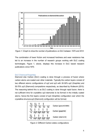
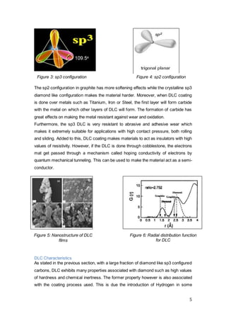
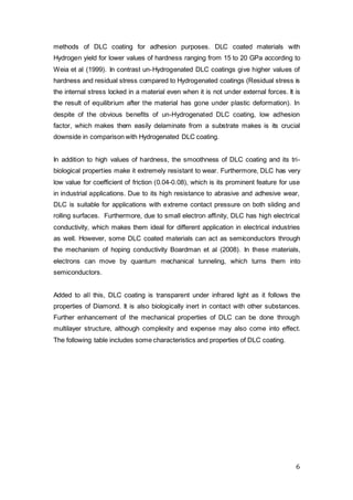
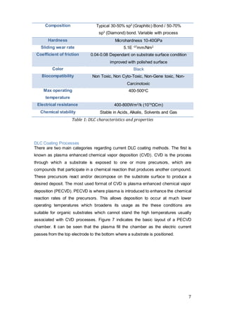
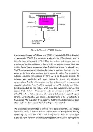
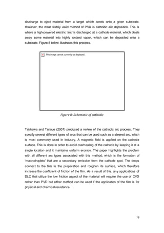
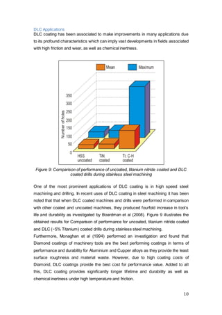
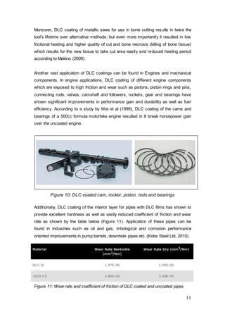
This document discusses diamond-like carbon (DLC) coating and its potential application to an industrial adhesive tape. It provides background on the history and development of DLC coating, describing the chemical and mechanical properties that make it useful for reducing friction. The document outlines different methods for depositing DLC coatings, such as plasma-enhanced chemical vapor deposition and cathodic arc deposition. It also reviews previous studies applying DLC coatings to materials like polymers and discusses how DLC coating can improve tool lifetime, reduce wear, and lower friction in applications like machining and bone cutting. The document aims to assess whether DLC coating could feasibly reduce the friction of an industrial adhesive tape for uses like attaching to drawer surfaces.
Super low friction diamond like carbon films made at the Argonne National Laboratory. This presentation is based on a paper published by Dr. Ali Erdemir (J. Vac. Sci. Technol. A 18(4), Jul/Aug 2000 1987-1992).
This presentation was made as a course requirement in the Department of Materials Science and Engineering, the University of Tennessee Space Institute at Tullahoma in Fall 2009.
Diamond-like carbon (DLC) coatings are recognized in many sectors as a promising way of controlling wear and the corrosion performance of components. DLC coatings are unique in the sense that they are a diverse group of amorphous carbon films with a wide range of engineering properties. This allows the tailoring of DLC coating properties for specific applications by choosing suitable deposition method and adjusting their architectures. In this presentation, three qualities of DLC coatings with the greatest relevance for oil and gas applications are identified; these include: (i) improved tribological properties; (ii) reduced corrosion; and (iii) anti-fouling properties. Successful applications of DLC coatings in petroleum production are reviewed, giving examples of protection against erosion-corrosion and fouling in flow control devices and in components where protection of internal surfaces in cylindrical structures is required. The application of DLC coatings in the oil and gas sectors is still very low, compared to other sectors; therefore, it is expected that demand for this type functional coatings has potential for steady growth.
COMPARATIVE STUDY OF COMPRESSIVE STRENGTH AND DURABILITY PROPERTIES ON GEOPOL...Journal For Research
The usage of practical advancement in structural building society has prompted the utilization of new materials with low environmental effects. One of the most commonly used construction material in the world is concrete, which is normally produced by OPC. However, the production of OPC has prompted ecological worries over the creation of CO2. Almost to create 1 ton of OPC 1 ton of CO2 is discharged to the atmosphere. With a specific end goal to diminish the utilization of OPC and CO2, the new concrete has been created, that is GEOPOLYMER CONCRETE. Latest research has demonstrated that it is conceivable to utilize fly ash or slag as a binder in concrete by activating them with alkali components through a polymerization procedure. This paper reports the point of interest of the test work that has been embraced to examine the strength and durability properties of ultra-fine slag and processed fly ash mortar mixes. At first specimens were casted for normal GGBS and fly ash in the ratio of 100:0, 75:25, 50:50, 25:75 and later for the best ratio (75:25), GGBS is replaced by ultra-fine GGBS by 7.5, 12 and 20%. Samples were compared with cured at ambient temperature and oven curing. The results showed that mix proportion of 20% replacement of ultra-fine GGBS gave the maximum strength for both oven and ambient curing (76.2 and 91.1 MPa). Even all the durability properties are within the permissible limits.
Done by Electron Group, Ahmed bin Hanbal Independent Secondary school for boys
Concrete : building material made by mixing cement with sand , gravel , water - of material things existing in material form that can be touched, felt or definite.
The presence of salt in soil or groundwater inside the concrete structure is a source of corrosion and cracks, as some salts attack the concrete and begin to fragment it such as sulfates
Inaugural lecture for Tomasz Liskiewicz, Professor of Tribology and Surface Engineering, Manchester Metropolitan University, Faculty of Science and Engineering
torm water normally refers to any precipitation that occurs during a rainstorm. At times, the term is used to specifically identify snowmelt or any other type of water that is not readily absorbed into the ground. In cities, this type of water is sometimes known as runoff water, referring to rain that is routed into sewage systems by way of drains. One of the major concerns with storm water today is the potential for polluting bodies of water as the runoff makes its ways to rivers, streams, and lakes.
A review on advanced ceramic processing techniquesAlokjyoti Dash
This Presentation enlists and describes most ceramic process and most parameters which affect these ceramic processing. A reader shall understand the basic of these presented process to fabricate unique ceramic materials
Fundamentals, synthesis and applications of Al2O3-ZrO2 compositesTANDRA MOHANTA
When the word “Ceramic” comes to our mind, we usually associate them with plates, saucers, cups and mugs. But, the word “Ceramic” encompasses more than just the word “plates” or “saucers”. Indeed, ceramic materials are hard and inherently brittle, but this is just the tip of the iceberg. They have multifarious properties and have acquired a status of high technical importance in the field of scientific research. Ceramics are the soul of the modern day’s structural applications owing to their high mechanical and thermal stability under different challenging conditions. They exhibit remarkable properties such as high hardness, high wear resistance, high corrosion resistance, high elastic modulus, high melting point and the ability to retain high strength at elevated temperatures. Alumina (Al2O3) is one such remarkable ceramic material known for its unique optical, mechanical and electrical properties. But the brittle nature of Al2O3 limits its use in certain engineering applications. Therefore, the strength of Al2O3 and Al2O3- based ceramics can be enhanced by tailoring the microstructural design through the application of strategic techniques that may involve secondary phase particle inclusion (such as Zirconia, ZrO2)
ORGANIC COATINGS FOR CORROSION PROTECTION OF TRANSFORMERS IN UNDERGROUND CHAM...Adriana de Araujo
Underground electrical transformers are frequently submitted to a very aggressive environment because of the stagnated water of underground chambers which is heated and contaminated. In Brazil, carbon steel structures of underground transformers are usually protected with coal tar epoxy paints in order to ensure their reliability. However, the use of this type of paints is being strongly restricted because coal tar contains complex mixtures of polycyclic aromatic hydrocarbons which contain many toxic and potentially carcinogenic substances. Aiming at replacing coal tar based paints by an environmentally friendly one; several paints were selected in the local market and submitted to performance tests in order to compare them with coal tar based paint. In addition, anodes were evaluated to study the application of galvanic cathodic protection in areas of metal exposure due to coating flaws. This paper presents and discusses the obtained results.
Os transformadores elétricos subterrâneos estão frequentemente expostos à corrosão intensa decorrente da estagnação de água aquecida e contaminada das câmaras subterrâneas. No Brasil, as estruturas de aço-carbono do transformador subterrâneo são usualmente protegidas com pintura de epóxi alcatrão de hulha que contém substâncias tóxicas e potencialmente cancerígenas. Com o objetivo de substituir as tintas à base de alcatrão de hulha por tintas ecologicamente corretas, tintas disponíveis no mercado nacional foram selecionadas e submetidas a ensaios de desempenho para a sua comparação com a tinta de alcatrão de hulha. Além disso, anodos foram avaliados para o estudo da aplicação de proteção catódica galvânica do metal exposto em áreas de falhas do revestimento. Este artigo apresenta e discute os resultados obtidos.
ARAUJO, A.; PANOSSIAN, Z; ALMEIDA, N.L; MARTINS, M.C.; JUNIOR, S.D.A. Organic coatings for corrosion protection of transformers in underground chambers. In: NACE INTERNATIONAL CONFERENCE & EXPO, 2012, Salt Lake City, Proceedings... Salt Lake City: NACE 2012.
Ordinary Portland Cement (OPC) production produces
substantial CO2 emission. Geopolymer Concrete (GPC)
will be of considerable cure to Global Warming related
with construction industry since GPC replaces OPC
completely or about 80% with industrial waste products. In
this study GPC was made up of Ground Granulated Blast
furnace Slag (GGBS) and Red Mud (RM) incorporating
hybrid fibres in various ratios. Results show that, among
all the mixes, one mix showed the best mechanical
properties owing to the incorporation of hybrid fibres
and reduction of Red Mud.
The Digital Public Library of America (DPLA) is a freely accessible public portal to cultural heritage information that contains more than 10 million images (photographs, maps, posters, postcards) textual items (manuscripts, correspondence, pamphlets, newspapers, yearbooks, eBooks), oral histories, sound and video files. Temple University Digital Projects Librarian and DPLA Volunteer Community Representative Doreva Belfiore discusses how the DPLA can help one find cultural and family heritage information to supplement genealogical research.
Characterization Studies of CdS Nanocrystalline Film Deposited on Teflon Subs...IJLT EMAS
In this article, different substrates for deposition of
CdS material have been discussed. Till date glass, mica, quartz,
ceramic, etc. are commonly employed substrates in thin film
growth. In the present work, CdS is deposited on Teflon
substrate by chemical bath deposition (CBD) method. Also the
films were deposited on different substrates like glass, copper
and zinc and compared with those prepared on Teflon substrate.
The films prepared on Teflon substrate were uniform, stable and
also showed good radiating property. These films were further
characterized by UV-VIS absorption spectral studies, SEM and
EDS studies.
Effect of PVD Coating and Carburizing on Wear Characteristics of Low Carbon S...IJERD Editor
Wear is a relative cyclic motion with small amplitude which occurs between two oscillating
surfaces, depending upon the loading conditions, material properties and environment. Surface Engineering
such as surface treatment, coating and surface modifications are employed to minimise the friction and improve
wear resistance of steel. In this work the low carbon steel substrate is coated with Al2O3 by using physical
vapour deposition process and the other sampling material is heat treated by carburizing process. In the present
study, the wear resistance of heat treated and coated steels were evaluated through the pin-on-disk using
variable loads and wear is measured by the wear track width and wear graphs are shown for coated material and
heat treated material. Finally, the comparison is concluded by observing the variations in wear characteristics
between the two samples. Furthermore morphological study of wear is made for in-depth analysis
Applications of SiC-Based Thin Films in Electronic and MEMS DevicesMariana Amorim Fraga
Mariana Amorim Fraga, Rodrigo Sávio Pessoa, Marcos Massi and Homero Santiago Maciel (2012). Applications of SiC-Based Thin Films in Electronic and MEMS Devices, Physics and Technology of Silicon Carbide Devices, Dr. Yasuto Hijikata (Ed.), InTech, DOI: 10.5772/50998. Available from: https://www.intechopen.com/books/physics-and-technology-of-silicon-carbide-devices/applications-of-sic-based-thin-films-in-electronic-and-mems-devices
Correlation between the Interface Width and the Adhesion Strength of Copper F...IOSRJAP
The present study has been conducted in order to determine the influence of negative bias voltage applied to substrate on adhesion of copper films deposited on carbon steel substrates. The adhesion strength has been evaluated by the scratch test. Coatings were deposited by a DC magnetron sputtering system. The substrates were firstly mechanically polished and then ion-etched by argon ions prior to deposition. Adhesion was found to increase with the bias voltage. The critical load had a value of 9.5 g for an unbiased substrate and reached 18.5 g for a bias voltage of 600 V. Equally important, the interface width, measured using Auger electron spectroscopy, increased as a function of the bias voltage. The width of the interface is related to the time of ion milling in the Auger spectrometer. The size of this width is obtained from the Auger elemental depth profiles through measuring the depth of the interface coating/substrate. The width had a value of 335 min with a bias of 600 V whereas it didn't exceed 180 min when the substrate was unbiased. Therefore, the effect of the bias voltage was to expand the interface because of the diffusion phenomenon and physical mixing of materials at the interface. Moreover, the critical load increased with the increase of the interface width.
Recent Developments on Silicon Carbide Thin Films for Piezoresistive Sensors ...Mariana Amorim Fraga
Mariana Amorim Fraga, Rodrigo Sávio Pessoa, Homero Santiago Maciel and Marcos Massi (2011). Recent Developments on Silicon Carbide Thin Films for Piezoresistive Sensors Applications, Silicon Carbide - Materials, Processing and Applications in Electronic Devices, Dr. Moumita Mukherjee (Ed.), InTech, DOI: 10.5772/20332. Available from: https://www.intechopen.com/books/silicon-carbide-materials-processing-and-applications-in-electronic-devices/recent-developments-on-silicon-carbide-thin-films-for-piezoresistive-sensors-applications
Rosa alejandra lukaszew a review of the thin film techniques potentially ap...thinfilmsworkshop
SRF is a surface phenomenon where only ~10 penetration depths are needed (l=40 nm for niobium), thus it has been recognized for some time now that it would be economically convenient to use thin film coated cavities. But problems arise with defects within 1 or 2 l of the surface or on the surface, and insufficient attention has been paid to this topic, including trapping of impurities like oxygen in defects as well as surface roughness enabling magnetic field pinning sites. Earlier attempts at CERN applied standard sputter PVD methods, but the grain size for the CERN Nb/Cu films was 100 nm, which is 10,000 times smaller than for conventional SRF cavities with the ensuing problems that appear at grain boundaries. Thus, these prior attempts showed higher surface resistance and worst Q-slope than bulk. I will review more modern approaches using higher energetic PVD methods for thin film deposition which offer promise to achieve thin films with improved superconducting performance.
This manuscript is about the concrete specification. The concrete specification testing is a process by which different tests are carried out such as compressive strength, carbonation depth, ASTM rapid chloride permeability, NDT chloride and initial surface absorption test (ISAT-10) to determine the quality and performance of the concrete in terms of strength, carbonation depth, chloride permeability and surface absorption.
Research Inventy : International Journal of Engineering and Science is published by the group of young academic and industrial researchers with 12 Issues per year. It is an online as well as print version open access journal that provides rapid publication (monthly) of articles in all areas of the subject such as: civil, mechanical, chemical, electronic and computer engineering as well as production and information technology. The Journal welcomes the submission of manuscripts that meet the general criteria of significance and scientific excellence. Papers will be published by rapid process within 20 days after acceptance and peer review process takes only 7 days. All articles published in Research Inventy will be peer-reviewed.
IJERA (International journal of Engineering Research and Applications) is International online, ... peer reviewed journal. For more detail or submit your article, please visit www.ijera.com
Electrochemical Supercapacitive Performance of Sprayed Co3O4 ElectrodesIJERA Editor
Nanocrystalline cobalt oxide (Co3O4) thin film electrodes were fabricated by spray pyrolysis method on conducting fluorine doped tin oxide (FTO) substrates using ammonia complexed with cobalt chloride (CoCl2. 6H2O) solution. The structural and morphological properties of Co3O4electrodes were studied using X-ray diffraction (XRD) and scanning electron microscopy (SEM).The surface morphology study showed the film formation of porous surface with clusters. The electrochemical supercapacitive properties ofCo3O4 electrodes were evaluated using cyclic voltammetry and galvanostatic charge-discharge method. The Co3O4electrodes showed maximum specific capacitance of 168 F/g in 1 M aqueous KOH electrolyte at the scan rate of 20 mV/s. The maximum specific energy and specific power of the cell are 2.2Wh/kg and 0.23 kW/kg, respectively.
Electrochemical Supercapacitive Performance of Sprayed Co3O4 Electrodes
DLC Report
1. The Frictional Effects of Diamond-Like-Carbon Deposited on a Substrate via
Plasma Enhanced Chemical Vapor Deposition
Contents
Table of Contributions ................................................................................................................................1
Introduction and Literature Review ...................................................................................................2
DLC History...................................................................................................................................................2
DLC Chemical Properties:..................................................................................................................4
DLC Characteristics................................................................................................................................5
DLC Coating Processes......................................................................................................................7
DLC Applications...................................................................................................................................10
Testing Method Selection .....................................................................................................................12
Alternative Testing Methods................................................................................................................13
Ball-on-Flat (Heimberg et al, 2001) ..........................................................................................13
Laboratory Bench Rig (Gangopadhyay et al, 2011) .....................................................14
Motored Valvetrain Rig for Friction Evaluations (Gangopadhyay et al, 2011)
............................................................................................................................................................................15
Twin-Disc Testing Rig (Löhr, 2006)..........................................................................................16
Methodology...................................................................................................................................................17
Calculations and Results.......................................................................................................................21
Calculations ...............................................................................................................................................21
Results:.........................................................................................................................................................26
Discussion........................................................................................................................................................33
MDF.................................................................................................................................................................33
Metal Sheet................................................................................................................................................35
Comparison................................................................................................................................................36
Conclusions and the future of DLC Coating ............................................................................38
Project Management - Critical Assessment.............................................................................40
2. 1
Table of Contributions
Member Contribution
Ali Maasoumian - Background research on friction
- Literature review over DLC chemical properties
- Research over DLC characteristics
- Research over DLC applications
- Testing set up and optimization
Amandeep Mankoo - Background research on friction
- Testing and setup
- Research over improvements on current methods
- Introduction and conclusion
Joseph Mendonca - Background research on DLC history
- Literature review over DLC coating methods
- Testing setup and optimization
- Report formatting
Mohammed Miah - Background research on testing methods
- Testing and data collection
- Methodology
- Research on DLC future applications
- Conclusion and discussions
Nakul Shah - Testing setup assessment
- Testing
- Data collection and calculations
- Data analysis
- Discussion
3. 2
Introduction and Literature Review
The optimization of a system is a key aspect in the field of Engineering, with
continuous improvements always being made to combat efficiency, a key component
of energy loss being friction. Many of today’s methods of overcoming frictional losses
are expensive, therefore a cost-effective method of reducing frictional losses is
investigated.
Diamond-like carbon (DLC) coating is a process in which a thin film of diamond-like
carbon is deposited on a substrate in order to improve the physical and chemical
resistance of the base material. This report examines the effect that DLC coating has
on the static and dynamic friction when applied to an industrial adhesive tape, this is
done in an attempt to assess its feasibility, with the overall aim being a
commercialised friction-reducing sticky tape, which can be stuck to a variety of
surfaces. Applications may include the underside of skis and sliding drawers in
domestic or industrial furniture.
DLC History
Hard amorphous carbon films were first mentioned by Schmellenmeier (1953). In his
investigation, the influence of an ionized acetylene atmosphere on the surfaces of
tungsten-cobalt alloys was investigated using a glow discharge system which is a
plasma formed by the passing of an electric current through a hydrocarbon
atmosphere. The aim of the experiment was to observe if tungsten carbide hard
metal surface layers could be produced. However, it was noticed that a hard
amorphous carbon film was deposited on the cathode of the direct current (DC) glow
discharge system. In a further study performed by Schmellenmeier (1956), it was
found that some of these micrometer thick layers had ‘structure-less’ regions but
others were formed of crystallites; which was identified as diamond by x-ray
diffraction.
The term ‘diamond like carbon’ was first used by Aisenberg and Chabot (1971). The
investigation focused on an ion beam deposition technique, which is the process of
applying a material to a substrate by using ion beams. The ion beam used consisted
on carbon and argon gas and when applied to the substrate, thin carbon films were
deposited on the graphite electrodes. An investigation into the properties of these
films was done and it was found that the coatings had favorable scratch and
chemical resistance as well as electronic insulation whilst being optically transparent.
4. 3
Around this period, other studies into the properties of these amorphous carbon films
were published. Spencer et al (1976) used x-ray diffraction and transmission electron
microscopy to study the structure of these films. The findings supported the research
done by Aisenberg and Chabot as it showed the same crystalline structure but
furthered the understanding by classing these crystalline compositions as either large
or small.
Since the mid 1970s, there have been constant advancements in deposition methods
and the characteristics of these films were characterized in detail. Weissmantel et al
(1977, 1979) reported on 2 different methods for the preparation of DLC coating. The
first is the dual beam technique through which a carbon target was bombarded with
argon ions and the carbon film produced from this was simultaneously bombarded by
a second ion source. The film produced was hard and described as ‘amorphous with
crystallites in the regions exposed to the highest ion densities.’
The second method comprised of using DC hot cathode ionization to generate
hydrocarbon ions in a benzene atmosphere, which bond to a substrate that has a
negative charge bias. The films produced were hard, partially optically transparent
and electrically insulating. Weissmantel and co workers described the material
structure as a mixture of nano-crystalline components consisting of graphite and
diamond like elements.
In the early 1980’s, a new quality that DLC films possess had been discovered.
Enke, Dimigen et al (1980) reported on the friction properties of DLC coatings
against steel. It was found that in contrast to graphite, the DLC films had noticeably
lower friction coefficients, especially under conditions of low humidity.
In the early 1990s work had commenced on manipulating the deposition processes
in order to optimize the properties of the coatings. Martinu et al (1992) worked to
increase the effectiveness of the radio frequency (r.f.) process. This was achieved by
running the process whilst simultaneously operating microwave radiation. The
addition of microwaves increases the ion fluxes on the substrate, which in turn
increases the deposition rate and increases the hardness by reducing the hydrogen
content present in the deposited film.
5. 4
Figure 1: Graph to show the number of publications on DLC between 1970 and 2012
The combination of lower friction and increased hardness and wear resistance has
led to an increase in the number of research groups working with DLC coating
technologies. Figure 1, above, displays this increase in DLC based research
publications since 1970.
DLC Chemical Properties:
Diamond Like Carbon (DLC) coating is done through a process of fusion where
carbon atoms are coated over other materials. Typically the carbon layers consist of
two different atomic configurations of sp2 and sp3 with 30-50% sp2 (Graphite) and
50-70% sp3 (Diamond) compositions respectively, as described by Wallwork (2010).
The reasoning behind this is as DLC coating is done through rapid fusion, there is
not sufficient time for crystalline sp3 diamonds to be formed in the initially coated
atoms; hence the first layers consist of sp2 (Graphite) configuration over which the
crystalline structure sp3 (Diamond) configuration will be formed.
Figure 2: Different Carbon states configurations
6. 5
The sp2 configuration in graphite has more softening effects while the crystalline sp3
diamond like configuration makes the material harder. Moreover, when DLC coating
is done over metals such as Titanium, Iron or Steel, the first layer will form carbide
with the metal on which other layers of DLC will form. The formation of carbide has
great effects on making the metal resistant against wear and oxidation.
Furthermore, the sp3 DLC is very resistant to abrasive and adhesive wear which
makes it extremely suitable for applications with high contact pressure, both rolling
and sliding. Added to this, DLC coating makes materials to act as insulators with high
values of resistivity. However, if the DLC is done through cobblestone, the electrons
mat get passed through a mechanism called hoping conductivity of electrons by
quantum mechanical tunneling. This can be used to make the material act as a semi-
conductor.
DLC Characteristics
As stated in the previous section, with a large fraction of diamond like sp3 configured
carbons, DLC exhibits many properties associated with diamond such as high values
of hardness and chemical inertness. The former property however is also associated
with the coating process used. This is due the introduction of Hydrogen in some
Figure 3: sp3 configuration Figure 4: sp2 configuration
Figure 5: Nanostructure of DLC
films
Figure 6: Radial distribution function
for DLC
7. 6
methods of DLC coating for adhesion purposes. DLC coated materials with
Hydrogen yield for lower values of hardness ranging from 15 to 20 GPa according to
Weia et al (1999). In contrast un-Hydrogenated DLC coatings give higher values of
hardness and residual stress compared to Hydrogenated coatings (Residual stress is
the internal stress locked in a material even when it is not under external forces. It is
the result of equilibrium after the material has gone under plastic deformation). In
despite of the obvious benefits of un-Hydrogenated DLC coating, low adhesion
factor, which makes them easily delaminate from a substrate makes is its crucial
downside in comparison with Hydrogenated DLC coating.
In addition to high values of hardness, the smoothness of DLC coating and its tri-
biological properties make it extremely resistant to wear. Furthermore, DLC has very
low value for coefficient of friction (0.04-0.08), which is its prominent feature for use
in industrial applications. Due to its high resistance to abrasive and adhesive wear,
DLC is suitable for applications with extreme contact pressure on both sliding and
rolling surfaces. Furthermore, due to small electron affinity, DLC has high electrical
conductivity, which makes them ideal for different application in electrical industries
as well. However, some DLC coated materials can act as semiconductors through
the mechanism of hoping conductivity Boardman et al (2008). In these materials,
electrons can move by quantum mechanical tunneling, which turns them into
semiconductors.
Added to all this, DLC coating is transparent under infrared light as it follows the
properties of Diamond. It is also biologically inert in contact with other substances.
Further enhancement of the mechanical properties of DLC can be done through
multilayer structure, although complexity and expense may also come into effect.
The following table includes some characteristics and properties of DLC coating.
8. 7
Table 1: DLC characteristics and properties
DLC Coating Processes
There are two main categories regarding current DLC coating methods. The first is
known as plasma enhanced chemical vapor deposition (CVD). CVD is the process
through which a substrate is exposed to one or more precursors, which are
compounds that participate in a chemical reaction that produces another compound.
These precursors react and/or decompose on the substrate surface to produce a
desired deposit. The most used format of CVD is plasma enhanced chemical vapor
deposition (PECVD). PECVD is where plasma is introduced to enhance the chemical
reaction rates of the precursors. This allows deposition to occur at much lower
operating temperatures which broadens its usage as the these conditions are
suitable for organic substrates which cannot stand the high temperatures usually
associated with CVD processes. Figure 7 indicates the basic layout of a PECVD
chamber. It can be seen that the plasma fill the chamber as the electric current
passes from the top electrode to the bottom where a substrate is positioned.
Composition Typical 30-50% sp2
(Graphitic) Bond / 50-70%
sp3
(Diamond) bond. Variable with process
Hardness Microhardness 10-40GPa
Sliding wear rate 5.1E -07
mm/Nm2
Coefficient of friction 0.04-0.08 Dependant on substrate surface condition
improved with polished surface
Color Black
Biocompatibility Non Toxic, Non Cyto-Toxic, Non-Gene toxic, Non-
Carcinotoxic
Max operating
temperature
400-500o
C
Electrical resistance 400-800Wm2
/k (1010
ΩCm)
Chemical stability Stable in Acids, Alkalis, Solvents and Gas
9. 8
Figure 7: Schematic of PECVD Chamber
A study was undergone by N. Cuong et al (2003) to investigate DLC films deposited
on polymers by PECVD. The team used a polycarbonate (PC) substrate, which is
thermally stable up to around 190°C. PC has low hardness and demonstrates poor
chemical and physical resistance. N. Cuong et al were able to overcome these poor
qualities by applying an amorphous carbon film to the surface of the polycarbonate.
The PC sample was cleaned with ethanol and dried in a vacuum desiccator. It is then
placed on the lower plate electrode that is cooled by water. This prevents the
substrate exceeding temperatures of 80°C. As a pre-deposition process, the
substrate was bombarded with argon plasma to remove any remaining
contaminations. The deposition process was then undergone with an approximate
deposition rate of 8nm/min. The films produced on the PC substrate were friction
tested using a ball on disk method, which found that hydrogenated carbon films
deposited had a friction coefficient as low as 0.3 as compared to a coefficient of 0.7
of the PC surface. Further work was also done to test resistance against organic
solvents. A drop of acetone was applied to the coating and to the PC surface for a
few seconds. After inspection, it was observed that the untreated surface had been
altered by the reaction whereas the DLC coating was not corroded.
The second categorical method is physical vapor deposition (PVD). This category
describes a variety of methods that use vacuum deposition to deposit thin films by
condensing a vaporized form of the desired coating material. There are several types
of physical vapor deposition such as sputter deposition, which utilizes a glow plasma
10. 9
discharge to eject material from a target which bonds onto a given substrate.
However, the most widely used method of PVD is cathodic arc deposition. This is
where a high-powered electric ‘arc’ is discharged at a cathode material, which blasts
away some material into highly ionized vapor, which can be deposited onto a
substrate. Figure 8 below illustrates this process.
Figure 8: Schematic of cathodic
Takikawa and Tanoue (2007) produced a review of the cathodic arc process. They
specify several different types of arcs that can be used such as a steered arc, which
is most commonly used in industry. A magnetic field is applied on the cathode
surface. This is done in order to avoid overheating of the cathode by keeping it at a
single location and it maintains uniform erosion. The paper highlights the problem
with all different arc types associated with this method; which is the formation of
‘macrodroplets’ that are a secondary emission from the cathode spot. The drops
connect to the film in the preparation and roughen its surface, which therefore
increase the coefficient of friction of the film. As a result of this, any applications of
DLC that utilize the low friction aspect of the material will require the use of CVD
rather than PVD but either method can be used if the application of the film is for
physical and chemical resistance.
11. 10
DLC Applications
DLC coating has been associated to make improvements in many applications due
to its profound characteristics which can imply vast developments in fields associated
with high friction and wear, as well as chemical inertness.
Figure 9: Comparison of performance of uncoated, titanium nitride coated and DLC
coated drills during stainless steel machining
One of the most prominent applications of DLC coating is in high speed steel
machining and drilling. In recent uses of DLC coating in steel machining it has been
noted that that when DLC coated machines and drills were performed in comparison
with other coated and uncoated machines, they produced fourfold increase in tool’s
life and durability as investigated by Boardman et al (2008). Figure 9 illustrates the
obtained results for Comparison of performance for uncoated, titanium nitride coated
and DLC (~5% Titanium) coated drills during stainless steel machining.
Furthermore, Monaghan et al (1994) performed an investigation and found that
Diamond coatings of machinery tools are the best performing coatings in terms of
performance and durability for Aluminium and Cupper alloys as they provide the least
surface roughness and material waste. However, due to high coating costs of
Diamond, DLC coatings provide the best cost for performance value. Added to all
this, DLC coating provides significantly longer lifetime and durability as well as
chemical inertness under high temperature and friction.
12. 11
Moreover, DLC coating of metallic saws for use in bone cutting results in twice the
tool’s lifetime over alternative methods; but even more importantly it resulted in low
frictional heating and higher quality of cut and bone necrosis (killing of bone tissue)
which results for the new tissue to take cut area easily and reduced healing period
according to Makino (2009).
Another vast application of DLC coatings can be found in Engines and mechanical
components. In engine applications, DLC coating of different engine components
which are exposed to high friction and wear such as pistons, piston rings and pins,
connecting rods, valves, camshaft and followers, rockers, gear and bearings have
shown significant improvements in performance gain and durability as well as fuel
efficiency. According to a study by Wei et al (1999), DLC coating of the cams and
bearings of a 500cc formula motorbike engine resulted in 8 break horsepower gain
over the uncoated engine.
Figure 10: DLC coated cam, rocker, piston, rods and bearings
Additionally, DLC coating of the interior layer for pipes with DLC films has shown to
provide excellent hardness as well as vastly reduced coefficient of friction and wear
rate as shown by the table below (Figure 11). Application of these pipes can be
found in industries such as oil and gas, tribological and corrosion performance
oriented improvements in pump barrels, downhole pipes etc. (Kobe Steel Ltd, 2010).
Figure 11: Wear rate and coefficient of friction of DLC coated and uncoated pipes
13. 12
Testing Method Selection
A set of criteria was constructed to provide a list of various testing methods that
would help determine the feasibility of DLC coated tape, these criteria can be
summarized as follows:
How resource intensive is the testing method?
This is significant as the pool of resources for this project is limited and any cost that
exceeds this limit would leave the project incomplete. In terms of resources this
encompasses financial budget and raw materials.
How valid is the testing method?
If this isn’t taken into consideration there is a high possibility that the project will be
moot and not provide any significant insight into the feasibility of DLC coated
adhesive tape, thus this should be the first question that is asked before any method
can be considered.
How accurate is the testing method?
This is different from validity as it indicates essentially how close the values
interpreted from the results are to the actual values, this is important in its own right
as the data obtained from an accurate testing method can be transferred and applied
in various other applications as true values.
How easily can the method be performed?
This refers to the skill cap required to perform the chosen method, this can refer to
any specialist tools that may be required to perform a certain method, whether
specific facilities are needed for the performed experiment.
With these questions taken into consideration a specific set of Design Criteria can be
obtained, a Minimalistic approach has to be taken in the selection process as the
physical resources available for the project are limited, this however cannot come at
the cost of legitimate data that is valid to draw conclusions from. The data itself does
not have to be to high level of precision and accuracy, this is because to test the
feasibility of DLC tape, the coatings only have to perform relative to other DLC
coatings of different thicknesses. The project is also short term and therefore the test
has to be relatively simple to perform thus allowing ample time for data analysis and
drawing conclusive evidence of the feasibility of DLC coated adhesive tape.
14. 13
Alternative Testing Methods
Ball-on-Flat (Heimberg et al, 2001)
Heimberg et al (2001) performed reciprocating ball-on-flat friction tests, utilising a
tribometer. An investigation was carried out into the effect of time and speed on
super-low friction behaviour of DLC coatings. The experiment was designed to
achieve friction coefficients down to 0.001 at atmospheric pressure in dry nitrogen,
with the friction behaviour explained in terms of gas adsorption. The coatings were
prepared by low temperature, plasma assisted chemical vapour deposition to 1µm
thickness on sapphire and steel balls, and on steel flats. The ball was loaded against
the flat to 9.8N. Each track was initially run-in for 1000 cycles at constant sliding
speeds, in order to find an average value for the friction coefficient.
The aim of this experiment was to achieve super-low friction, and therefore carried
out to a high degree of accuracy. Friction coefficients as low as 0.007 were obtained
at high speeds, which were slightly higher than expected. This was due to the
interaction time between the surfaces. At shorter test times the average friction
coefficient decreased to 0.003. This particular method takes a relatively time-
consuming approach to calculate the friction coefficient. Due to this, a more time-
effective method to calculate the average friction coefficient was developed. The
same method of applying the DLC coating, PCVD, was also used. However in the
ball-on-flat experiment, the coating was applied onto metal, whereas we are applying
the coating to tape. A different coating thickness was also used for the ball-on-flat
experiment.
Figure 12: Ball-on-Flat
Pin-on-Disc
15. 14
Kano and Yoshida (2010) carried out pin-on-disc tests, in which ultra-low friction of
DLC coating with lubricant was investigated. Both reciprocating and rotating sliding
tests were conducted. The experiment was designed to investigate the theory that
reducing the mechanical friction in an engine would improve the fuel economy, and
the effect that this method would have on the friction between the cam and follower
of an engine. Three types of coating were applied to each surface, with and without
lubrication, in order to find the best combination for optimal friction coefficient. While
it was vital to the proposed experiment, this procedure requires extra machinery and
funding as well as copious amounts of time. The results showed that the ta-C(T)
coating, coupled with the oleic acid lubrication, provided the lowest friction
coefficient. When considering the practical applications of the DLC coated sticky
tape, lubrication can be factored out as it is irrelevant.
Figure 13. Pin-on-Disc Sliding Test
Laboratory Bench Rig (Gangopadhyay et al, 2011)
The test utilised a Plint TE77 test rig. An uncoated, reciprocating polished cylinder
was loaded against a coated steel flat, with test duration of one hour, conducting
tests with and without lubrication. The aim for this experiment was to understand the
interactions of lubrication additives with DLC coating. As stated previously, the use of
lubrication is irrelevant for the adhesive tape tests. While the method of polishing to
decrease surface roughness is useful in obtaining the desired results, it is difficult
and time-consuming to polish the tape and therefore this process will not be carried
out. However, wiping the tape with disinfectant after each test run will be necessary
as it is a quick process and allows for smoother contact between surfaces. The
16. 15
cylinder was loaded to the flat at 240N, whereas the sliding test will not require any
load, allowing for a simpler method. Results for this testing method showed that the
friction coefficient decreased with time. This contradicted the ball-on-flat method, due
to the use of lubricants. Results also showed that unlubricated tests had a lower
friction coefficient overall. A rise in oil temperature also gave higher friction
coefficients. However the surface roughness did not have much effect on the friction
coefficient, with no visible wear observed on either contact surface.
Figure 14. Plint PE77 Test Rig (Gangopadhyay et al, 2011)
Motored Valvetrain Rig for Friction Evaluations (Gangopadhyay et al, 2011)
A rig was constructed in order to represent an actual engine. This method of testing
the effect of lubricants on DLC coatings is highly expensive due to the technology
applied and materials used. Aside from conducting lubrication tests, the rig was run
at various speeds in order to evaluate friction torque, resulting in lengthy tests.
Results showed that the friction torque decreased with increasing engine speed,
suggesting the system operates in a mixed lubrication regime. The polished buckets
showed substantial friction reduction at all speed, confirming the importance of
surface roughness. The unlubricated DLC coating test showed significant reduction
in friction coefficient compared to the steel-steel pairing, due to the formation of a
transfer layer. The friction coefficient was slightly higher with oil than without, and the
wear was higher with DLC coating than without, in lubrication tests.
17. 16
Figure 15. Motored Valvetrain Rig (Gangopadhyay et al, 2011)
Twin-Disc Testing Rig (Löhr, 2006)
Wear tests were carried out on different DLC coatings under lubricated and dry slip-
rolling friction in a twin-disc testing rig. The analysis of acoustic emission (AE)
provided an easy and comfortable tool for monitoring the wear life of DLC coatings.
Steel samples with a thin DLC coating were tested under both lubricated and dry slip-
rolling friction in an Amsler-type twin-disc wear tester. Two disc specimens formed
the test setup, rolling against each other with a slip of approximately 10%. A pressure
of up to 2.3GPa was observed in the centre of the contact area. A steel bearing
served as the substrate of the DLC coating as well as the material of the counter
body. Only the cylindrical specimen was coated with an interlayer and a DLC-coating
using AE.
The experimental setup is simpler than other testing methods, as it uses two discs,
one of which is coated. The main difference is that it incorporates a sensor, which
measures the acoustic emissions. Acoustic emissions such as this are related to the
irreversible changes that a material undergoes in its internal structure.
18. 17
Figure 16: Twin Disc Wear Tester (Löhr, 2006)
Depending on the intended application, testing methods for DLC coating will differ. A
test was carried out to investigate the effect that DLC coating has on the frictional
properties of orthodontic wires. Two types of wire (nickel-titanium and stainless steel)
were coated with DLC. Three types of brackets, a conventional stainless steel
bracket and two self-ligating brackets, were used for measuring static friction. DLC
layers were observed by three-dimensional scanning electron microscopy (3D-SEM),
and the surface roughness was measured. Frictional forces and surface roughness
were compared by the Kruskal-Wallis and Mann Whitney U-tests.
This method is carried out on a relatively small scale due to the intended application.
Two materials were used for coating. Our experiment involved the use of steel and
MDF as the counter surface for the DLC coating. (Muguruma et al, 2011)
Methodology
As mentioned prior the testing method is required to meet a few specifications before
it can be considered as the chosen method. A factor to take into consideration is that
the data analyzed is relative, this means that systematic errors that maintain a
constant effect on all results are irrelevant, as this will not affect the result’s worth as
they are still valid for the purpose of this investigation.
The chosen testing method involves a metal block of dimensions
79mmx50mmx20mm and weight 623 grams placed on a ramp that can be adjusted
19. 18
in slope angle at a range of intervals until points of both static and dynamic friction
can be observed.
The metal block will have tape attached to its long faces with different thicknesses of
DLC coating, all of which will be tested and compared to one another. The ramp had
to be built using two separate panels of MDF, both of dimensions
800mmx27mmx12mm attached together using a flexible metal hinge, the hinge
allowed for the ramp itself to be adjustable. For the first set of testing, a separate
wooden block was used as a slider to achieve fixed variation in slope angle. This
method however only allowed for a very small range of different slope angles and
also lacked the level of precision that was necessary when adjusting the slope angle,
also it required manual movement increasing the effect of human error on the results
and thus making the results less reliable.
Thus a new method of adjusting the slope angle would be required, instead of using
a wooden block as a manual sliding mechanism, a scissor lift of appropriate
dimensions was used instead, this piece of equipment provided a much larger range
Figure 18: The different thicknesses of
DLC coated tape with no coating on
the left 0.8 microns in the middle with
1.2 microns on the right
Figure 20: Wooden block used as
slider
Figure 17: Metal block
Figure 19: Constructed Incline
Plane
20. 19
of heights while providing precise height adjustment thereby allowing for more
accurate observations.
The MDF surface would also need to be taken into consideration as it was providing
inconsistent results as well as the observation points exceeding the large range of
the scissor lift, this meant that a surface with a lower coefficient of friction was
necessary so that the observation points occur at smaller angles that the scissor lift
can reach, to achieve this a metal sheet was attached to the MDF surface and was
tested following the same parameters as the MDF surface.
With the metal block placed at a fixed point on the ramp, the ramp was moved
steadily through a range of increased slope angles whilst being stopped at regular
intervals. At these intervals energy was applied to the system in the form of a simple
tap to the testing rig at a fixed location, after the tap the metal block would be
observed to see if it had reached a certain point, the points that require observing are
when static friction occurs and when dynamic friction occurs.
This method of testing, as the analysis is relative, requires consistency in the defined
points (Datum points) in order to yield valid results since the results are only
compared to each other. With this taken into account the point of static friction has
been quantified for this experiment as the point when the metal block moves a
Figure 21: Scissor lift as
used in experiment
Figure 22: Metal hinge used
for the ramp
Figure 23: Sheet Metal used as surface
21. 20
Figure 25: Diagram representing the
use of similar triangles to calculate
the angle
considerable distance and then stops, a considerable distance in this case is
approximately half the length of the block. The point of dynamic friction is much
easier to quantify and observe, as it is the point that the metal block begins moving
freely without stopping, in essence friction has been overcome.
When it comes to measuring the actual results, the desired information is the incline
plane angle with the horizontal, however measuring this angle manually inputs a lot
of human error, to avoid this basic trigonometry is used to calculate the angle
instead, to further reduce human error the elevated height is only measured from a
predetermined datum point that is constant throughout the experiment. The reason
that measuring the length is unnecessary is because the triangles are similar,
therefore the angle will remain constant, this helps reduce human error by reducing
the number of manual measurements that need to be taken thus making it more
effective in providing valid data.
B
E
F
A
C DG
Figure 24: Datum point for height
measurements
Figure 26: Experimental rig set up
22. 21
Calculations and Results
Calculations
The aim of this experiment is to obtain the friction coefficient values for the different
surface types. This was achieved by using calculations for an inclined plane, such as
the weight components. Figure 27 shows how the experiment was modelled
mathematically for the analysis. Table 3 shows the definition of the notation from the
model.
Figure 27: Mathematical Model of Experiment
A Metal Block
B Scissor Lift
C Wooden Ramp
D Metal Sheet
E Dial
F Metal Hinge
G Datum Point
Table 3: Notations and definitions of mathematical model
Notation Definition (unit)
m Mass (kg)
mg Weight (N)
mgcosθ = N Normal/Reaction forces (N)
Mgsinθ Driving force (N)
f Frictional force
θ Plane angle (degrees)
Table 2: Experimental rig components
23. 22
In the experiment, the values that were obtained are the ‘adjacent’ and ‘opposite’
distances of the right angle triangle. As mentioned in the methodology the adjacent
distant was kept constant at 400mm in order to reduce the factor of error in the
obtained data. Table 4 shows the values obtained from the experiment for an MDF
surface, and table 5 shows the values obtained from a steel plate surface.
Table 4: Experimental values of MDF
Using the trigonometric function ‘tan’, where 𝑡𝑎𝑛( 𝜃) =
𝑜𝑝𝑝𝑜𝑠𝑖𝑡𝑒
𝑎𝑑𝑗𝑎𝑐𝑒𝑛𝑡
, the plane angle can
be calculated, as shown in table 3 to 2 . The excel formula used is:
=DEGREES(ATAN(Opposite/Adjacent)). Excel does its trigonometric calculations in
radians, whereas the angles was preferred in degrees.
MDF
Static Dynamic
A
(mm)
O
(mm)
A
(mm)
O
(mm)
metal 400 77 400 140
400 73 400 127
400 71 400 126
400 72 400 140
400 70 400 113
thin 400 84 400 91.5
400 85.5 400 90
400 88.5 400 89.5
400 88 400 89
400 88.5 400 90
thick 400 80.5 400 86
400 81 400 83
400 79 400 85
400 80 400 83
400 78 400 82
Steel Plate
Static Dynamic
A
(mm)
O
(mm)
A
(mm)
O
(mm)
tape 400 90 400 101
400 92 400 101
400 95 400 100
400 90 400 107
400 91 400 103
thin 400 86 400 96
400 84 400 96
400 85 400 95
400 85 400 95
400 86 400 96
thick 400 80 400 90
400 79 400 92
400 77 400 93
400 79 400 92
400 80 400 93
Table 5: Experimental values of Steel Plate
24. 23
The next parameter that needs to be calculated is the driving force. The driving force
is the component of the metal blocks weight that is dragging the block down the
slope. The mass of the block is a constant value that is weighed to be 0.623kg. Using
this mass value, and the value of constant gravitational acceleration, the weight of
the steel block can be calculated using a simplified Newton’s second Law 𝑭 = 𝒎𝒂
where F is the force, m is the mass and a is the acceleration . This makes the weight
of the steel block 6.11163 N. This force is pulling the block downwards,
perpendicular to the floor, not the inclined slope as this is an effect of gravity which
pulls objects towards the earths centre. The driving force is the force vector that is
parallel to the inclined slope. This is calculated via simple trigonometry by multiplying
the weight of the block by the sine of the plane angle: 𝑚𝑔𝑠𝑖𝑛(𝜃). This parameter is
very important when comparing static and dynamic friction. The driving force for a
static friction test theoretically is also equal to the frictional resistance force applied
by the two surfaces, to stop the block from slipping down the slope. As the angle is
MDF Metal Plate
static dynamic static dynamic
Ө
(degrees)
Ө
(degrees)
Ө
(degrees)
Ө
(degrees)
Metal/Tape 10.90 19.29 12.68 14.17
10.34 17.61 12.95 14.17
10.07 17.48 13.36 14.04
10.20 19.29 12.68 14.98
9.93 15.77 12.82 14.44
thin 11.86 12.88 12.13 13.50
12.07 12.68 11.86 13.50
12.48 12.61 12.00 13.36
12.41 12.54 12.00 13.36
12.48 12.68 12.13 13.50
thick 11.38 12.13 11.31 12.68
11.45 11.72 11.17 12.95
11.17 12.00 10.90 13.09
11.31 11.72 11.17 12.95
11.03 11.59 11.31 13.09
Table 6: Plane angle for all tests
25. 24
increased gradually, so is the driving force component. The angle is increased until it
is observed that the block reached the static point of friction as defined in the
methodology section, which for the purpose of this testing is more convenient. This
demonstrates that the driving force has now equalled or ever so slightly surpassed
the frictional resistance value. This value is very important when working out the
friction coefficient µ. For the dynamic tests, the static frictional resistance is used
because theoretically, this value is constant for the same two frictional surfaces. The
Driving force is shown in table 5, to 2d.p.
The other component that the weight of the block produces is the force that the block
presses perpendicular to the inclined plane. This force keeps the block planted on to
the inclined surface. According to Newton’s third law of motion, the inclined plane is
applying an equal force back onto the block. This force is known as the reaction
force. This can be calculated by using simple trigonometry again and with the same
formula as the driving force, except a cosine function is used: 𝑚𝑔𝑐𝑜𝑠(𝜃). This is
useful as it has a direct link to the calculation of the coefficient of friction. This is also
shown in table 7.
MDF Metal Plate
Driving
Force
Reaction
Force
Driving
Force
Reaction
Force
Metal/Tape 1.16 5.96 1.34 5.93
1.10 5.96 1.37 5.93
1.07 5.95 1.41 5.93
1.08 5.96 1.34 5.90
1.05 5.96 1.36 5.92
thin 1.26 5.98 1.28 5.94
1.28 5.98 1.26 5.94
1.32 5.98 1.27 5.95
1.31 5.98 1.27 5.95
1.32 5.98 1.28 5.94
thick 1.21 5.99 1.20 5.96
1.21 6.00 1.18 5.96
1.18 6.00 1.16 5.95
1.20 6.00 1.18 5.96
1.17 5.99 1.20 5.95
Table 7: Weight components
26. 25
The friction coefficient is calculated using the formula: 𝐹𝑅 = 𝜇 × 𝑅, where FR is the
frictional resistance, µ is the coefficient of friction, and R is the reaction force exerted
by the inclined plane. It is this parameter that we expect to minimize using the DLC
coating. This means that less force is required to move the object down the inclined
slope. As mentioned previously, the frictional resistance for dynamic tests will be the
same as the static tests, as that is the maximum friction experienced. Table 8 shows
these values, and table 9 shows the average of the 5 repetitions for each test.
Table 8: Friction coefficients for all tests
MDF Metal Plate
Static Dynamic Static Dynamic
µ µ µ µ
metal 0.1925 0.200273 0.225 0.226402
0.1825 0.188367 0.23 0.231183
0.1775 0.183234 0.2375 0.238184
0.18 0.18769 0.225 0.22723
0.175 0.179127 0.2275 0.229068
thin 0.21 0.210826 0.215 0.216166
0.21375 0.214254 0.21 0.211353
0.22125 0.221367 0.2125 0.213641
0.22 0.220116 0.2125 0.213641
0.22125 0.221426 0.215 0.216166
thick 0.20125 0.201803 0.20 0.201019
0.2025 0.202699 0.1975 0.198816
0.1975 0.198084 0.1925 0.194071
0.2 0.200294 0.1975 0.198816
0.195 0.195375 0.2 0.201347
MDF Metal plate
static dynamic static dynamic
metal 0.1815 0.187738 - -
tape - - 0.229 0.230413
thin 0.21725 0.217598 0.213 0.214193
thick 0.19925 0.199651 0.1975 0.198814
Table 9: Averages of all tests
27. 26
The Metal Block
Results:
Figure 28: Data for each repetition of the experiment for static friction using MDF
0.15
0.16
0.17
0.18
0.19
0.2
0.21
0.22
0.23
1 2 3 4 5
coefficientoffriction
test number
Data trend of static tests with MDF
metal
thin
thick
L
D
H
D = 20 mm
L = 78 mm
H = 51 mm
Area = 0.00156 m2
Mass/Weight = 0.623kg/6.11163N
The Area is defined as the surface area for one of the surfaces that
will be making contact with the inclined plane for the purpose of
testing, therefore this means that these faces will be the ones that
are DLC coated as well.
28. 27
Figure 29: Data for each repetition of the experiment for dynamic friction using MDF
Figure 30: Comparison of data spread for each testing element and the averages, for
static tests on MDF
0.15
0.16
0.17
0.18
0.19
0.2
0.21
0.22
0.23
1 2 3 4 5
coefficientoffriction
test number
Data trend of Dynamic tests with MDF
metal
thin
thick
0.15
0.16
0.17
0.18
0.19
0.2
0.21
0.22
0.23
metal thin thick
coefficientoffriction
Testing element
Data trend of static tests with metal, thin
and thick, on MDF
test1
test2
test3
test4
test5
average
29. 28
Figure 31: Comparison of data spread for each testing element and the averages, for
dynamic tests on MDF
Figure 32: Data for each repetition of the experiment for static friction using Metal
plate
0.15
0.16
0.17
0.18
0.19
0.2
0.21
0.22
0.23
metal thin thick
coefficientoffriction
Testing Element
Data trend of Dynamic tests with metal,
thin and thick, on MDF
test1
test2
test3
test4
test5
average
0.15
0.16
0.17
0.18
0.19
0.2
0.21
0.22
0.23
0.24
0.25
1 2 3 4 5
coefficientoffriction
test number
Data trend of static tests with Metal plate
Tape
thin
thick
30. 29
Figure 33: Data for each repetition of the experiment for dynamic friction using Metal
plate
Figure 34: Comparison of data spread for each testing element and the averages, for
static tests on Metal plate
0.15
0.16
0.17
0.18
0.19
0.2
0.21
0.22
0.23
0.24
0.25
1 2 3 4 5
coefficientoffriction
test number
Data trend of Dynamic tests with Metal
plate
tape
thin
thick
0.15
0.16
0.17
0.18
0.19
0.2
0.21
0.22
0.23
0.24
0.25
tape thin thick
coefficientoffriction
Testing element
Data trend of static tests with metal, thin
and thick, on Metal plate
test1
test2
test3
test4
test5
average
31. 30
Figure 35: Comparison of data spread for each testing element and the averages, for
dynamic tests on Metal plate
Figure 36: Comparison of averages of static and dynamic tests, for all testing
elements on MDF
0.15
0.16
0.17
0.18
0.19
0.2
0.21
0.22
0.23
0.24
0.25
tape thin thick
coefficientoffriction
Testing element
Data trend of dynamic tests with metal,
thin and thick, on Metal plate
test1
test2
test3
test4
test5
average
0.16
0.17
0.18
0.19
0.2
0.21
0.22
0.23
metal thin thick
CoefficientofFriction
Testing element
Average µ for MDF
static
dynamic
32. 31
Figure 37: Comparison of averages of static and dynamic tests, for all testing
elements on Metal plate
Figure 38: Comparison between static and dynamic values for both testing surfaces,
for the thin testing element
0.18
0.19
0.2
0.21
0.22
0.23
0.24
tape thin thick
CoefficientofFriction
Testing element
Average µ for Metal Plate
static
dynamic
0.21
0.211
0.212
0.213
0.214
0.215
0.216
0.217
0.218
MDF Metal plate
CoefficientofFriction
Testing Surface
MDF vs metal plate Thin comparison
thin Static
Thin Dynamic
33. 32
Figure 39: Comparison between static and dynamic values for both testing surfaces,
for the thick testing element
Figure 40: Comparison of all test values for thin element
0.196
0.1965
0.197
0.1975
0.198
0.1985
0.199
0.1995
0.2
MDF Metal plate
CoefficientofFriction
Testing Surface
MDF vs metal plate Thick comparison
thin Static
Thin Dynamic
0.204
0.206
0.208
0.21
0.212
0.214
0.216
0.218
0.22
0.222
0.224
1 2 3 4 5
CoefficientofFriction
Test Number
MDF vs Metal in thin static and dynamic
static MDF
dynamic MDF
static Metal
dynamic Metal
34. 33
Figure 41: Comparison of all test values for thick element
Discussion
MDF
Figures 28 and 29 display a comparison of the experiments. For different testing
elements, it is noticeable that for both the static and the dynamic tests the metal
surface has the lowest coefficient of friction throughout all 5 repetitions. This deviates
from our expectations, as we expect the metal to demonstrate a higher frictional
coefficient than the DLC films. These anomalous results could be attributed to the
actual surface of the metal block that made direct contact with the inclined plane.
This MDF surface, after repeat testing, may have formed slip lines that are parallel
with the motion of the block, hence increasing the size of the plane angle that the
points of static/dynamic friction occur. This is because the surface finish is not taken
into consideration when calculating the value for the coefficient of friction, therefore
the minimal contact on the MDF board caused by the slip lines reduce the friction.
This factor becomes even more valid when taking into account that the DLC coated
tape overlapped the metal surface. This means that for the DLC friction tests, the slip
lines were not a present factor as the surface dimensions were different and
therefore could not be utilized in a similar manner as when the bare metal surface
was used.
0.186
0.188
0.19
0.192
0.194
0.196
0.198
0.2
0.202
0.204
1 2 3 4 5
CoefficientofFriction
Test Number
MDF vs Metal in thick static and dynamic
static MDF
dynamic MDF
static Metal
dynamic Metal
35. 34
The MDF board is made from bonding multiple wood fibres together using an
adhesive, thus the testing surface was not ideal since it is not uniform throughout the
wooden surface. Therefore each test had to start at the exact same position on the
MDF board; otherwise it would not have been an accurate test. However this method
of controlling variables produces the issue of repetitive wear on the relevant
surfaces. Subsequently after each test, the position used as the initial starting
position would receive some wear, thus making that particular location smoother than
before causing a systematic error that will have a significant effect on further testing.
Another by-product of repetitive use is physical erosion of the DLC coating, which
makes the film surface rougher and thus increases friction. We see this in action for
the thin element especially; which demonstrated surface damage after the first few
tests. This does plateau after test 3, suggesting that the wear and tear on the
elements was only done to the weak bonded regions as the material that had not
been worn away was intact, this however could be a factor of the irregularities on
both the finish of the metal block and the surface of the inclined plane.
The results displayed by figures 28 and 29, show that all three elements had very
similar friction coefficients after the first test, as none of the previously mentioned
biases were in play, therefore that set of results are the most reliable. From here, the
difference between the coatings increase as the aforementioned biases begin to take
effect; increasing systematically after every test. Despite this, the results followed the
expected trend, in that the thicker DLC element experiences less friction than the thin
equivalent. This is the natural assumption as a thicker DLC coating means that the
properties of the DLC substrate are more prominent, due to the fact that they are less
influenced by the metal surface underneath.
Figures 30 and 31 show how the data is spread for the respective testing elements,
and the average trend for each element. These graphs show how widely distributed
the data is for the static and dynamic tests. We can see that the results for the static
and dynamic friction have very little difference in terms of range between various
results, suggesting that both of the respective friction coefficients are similar. Also the
similarities between the results make it seem as if they are consistent repetitions,
except for one point in the metal element testing set that occurs at a significant
distance above its relative test values, seeming to deviate away from the rest. This
anomalous result could very well be deduced from human error as the plain metal
surface was the first set of tests performed and therefore the testing procedure was
not well versed at this point. Figures 28 and 29 share the same evidence in terms of
36. 35
the comparison between the dynamic and static values. Although it does look like an
outlier, it there is a valid explanation for its presence. We also see the previously
mentioned anomaly of the metal element producing a much lower friction coefficient
in comparison to the other two elements
Metal Sheet
The data obtained from the tests which implemented the metal sheet (graphed and
shown in figures 32-35) are much more promising than the MDF results. Figures 32
and 33 show the data trends for the three testing elements; uncoated tape, thin DLC
coating, and thick DLC coating. In these tests, plain adhesive tape was used as a
testing element instead of the metal surfacing.
The first reason for applying the tape is that it has a much more uniform surface in
comparison to the metal surface. This means that there are less parameters that
could potentially affect the results. Another reason for using the tape is because the
metal sides used for testing were already used for the DLC coating strips. The tape
was the same tape that was used as the adhesive for the DLC coatings, therefore
the comparison was more consistent. If the metal surface was required to be used,
the DLC coatings would have to be removed, and the surface would have to be
polished to remove any adhesive stuck onto the metal. This process could greatly
deter the results of the experiment.
The figures 32 and 33 show exactly what would be expected from the experiments
for each test. The figures show that the highest resistance to motion is the plain tape
surface, next is the thin coating, and finally the thick coating. This observation is
consistent with every repetition of the test, as well as the static and dynamic tests.
The variation from the average test values is not significant, confirming the reliability
of the results. There is a slight abnormality in tape results for the third test, where the
friction coefficient is noticeably higher than the rest of the results. This is in fact
expected, because during the test we realised that the tape accumulated some
contamination, which needed to be removed before any other tests continued. After
removing this small abnormality the results show a much more consistent trend. By
using the metal sheet, we removed the effect of compression on the fibres on the
MDF. The effects of this change are shown in the figures, as the data trend for all
friction tests does not decrease, staying more parallel to the horizontal axis.
37. 36
Figures 34 and 35 show how the data is spread for each testing element, as well as
how each element compares with the other. Both graphs show practically identical
graphs, meaning that the differences between the static and dynamic friction
coefficients are miniscule. For each testing element, we see that there is extremely
small deviation from each result, thus demonstrating the reliability of these
experiments. The trends of averages for each element are very satisfying. It shows
that as the DLC coating gets thicker, the friction of the surface reduces too. This is
represented with a linear looking line on the graph. This is exactly what we expect
from these tests and shows that choosing the tape did in fact deliver more concise
results.
Comparison
Figure 36 and 37 show the comparison of the averages of static and dynamic
coefficients of friction, for each testing element and testing surface. Straight away,
we see that there is a concern with the metal results on the MDF, and this issue has
been discussed above. The metal plate graph shows a more comforting negative
correlation as the DLC coating increases. A notable observation would be that for all
test averages, the static friction is always lower than the dynamic coefficient of
friction. This is a desirable result, duly because of the definitions of static and
dynamic frictions the static friction is always lower than dynamic friction. For the MDF
metal test, the dynamic is substantially higher than the static. This could be because
of non-uniformity of both the MDF and the metal surface. This means that a greater
driving force is required to overcome many contacts of the grooves on both surfaces,
that keep 'hooking' onto each other, stopping the steady flow to characterise the
result as dynamic.
Figures 38 and 39 display a comparison of the different testing surfaces with both
static and dynamic, with respect to the thin and thick DLC coatings. It is seen
immediately that the MDF has a much higher coefficient of friction compared to metal
plate. This is mostly because of the high friction surface of the MDF where the
surface is not uniform and it is comprised of fibers instead of a smooth one piece
surface. The other noticeable fact is that the difference of static and dynamic for both
coatings, is much larger with the metal plate than the MDF wood. A reason for this
could be because the metal surface or the coating was not cleaned properly, thus
leaving contaminants, making it much harder for the block to slide down the inclined
plane, increasing the result for dynamic tests. Even with this difference, when
38. 37
comparing numerically, the difference is practically non effective, as the difference is
in the thousandths.
Figures 40 and 41 show how the coefficient of friction varies with the static and
dynamic tests for the two testing surfaces, with respect to the DLC coating thickness.
It is show in both graphs that for most of the tests, the MDF has a higher coefficient
of friction than the metal plate, but there are two tests (test 1 for thin, and test 5 for
thick) where the metal plate has a higher static and dynamic coefficient of frictions.
These could be abnormalities, although the differences are excusable, as they would
not have any practical difference to the experiments. Figure 14 shows that as the
tests progress, the coefficient of friction increases for the static and dynamic MDF.
The reason has been mentioned previously, where the coating on the adhesive
would get scratched after each test, thus increasing its resistance to surface slip. We
see that every other trend on both graphs has some oscillations but numerically, they
are all stable towards an average figure that doesn't deviate away from all the
results. This shows the consistency and reliability of the results obtained from the
experiment.
Other conditions could have an impact on the results of the experiments, such as the
humidity and the temperature of the room. The humidity would affect the MDF, and
the resistance of micro condensation on the steel and the testing elements. The
temperature would mostly have an effect on the metal block, as it would increase the
surface area, thus spreading or concentrating the force and resistance over the area.
This could have an effect on the pressure exerted by the weight of the block, as it is
inversely proportional to area.
39. 38
Conclusions and the future of DLC Coating
The main objective of this investigation was to discover how feasible DLC coated
adhesive tape is as a low friction material. The idea behind it being that the DLC tape
can be conveniently placed on various different surfaces and help enhance some
sort of feature using its valuable properties, an example being the inside of a chest of
drawers to help the drawers to be extracted smoothly.
With this in mind the testing showed, although with the anomaly of the metal block
itself, that the DLC coating possessed superior properties in terms of being a low
friction material. This can be concluded from the relatively much lower coefficients of
friction obtained from the DLC coated materials, this claim can be supported further
by the thicker DLC coating showing more promise than the thinner coating, therefore
a positive relationship exists between the thickness of the DLC coating and the
coefficient of friction.
However there is still a lot left desired from how the testing method that was
performed. A key benefit of this method was its simplicity, however this criteria was
so critical due to the time constraint that it came at the cost of a truly accurate and
precise testing method. A key drain in the precision was the means of applying
energy to the system, this force was generated by a human element and
subsequently is prone to human error. In hindsight, this step of the experiment could
have been automated using a small electric fan of some sort that applies a
continuous subtle force, this would have reduced the time significantly between
intervals and allowed for more accurate results that in turn would provide clearer
evidence. Another source of error was the manual increase of the plane angle. This
could have been automated as well, but more importantly the plane angle was not
sensitive enough to the rotation of the dial, and as a result significantly reduced the
precision of the recorded data.
Other researchers previously performed similar testing that shared the same premise
albeit with one key difference. This difference was that not only the DLC coating
applied was applied, but various different lubricants were tested on top of the coating
as well, this was in an attempt to find the best combination that provides the most
useful properties. The reason this statement is relevant is because these lubricants
could in effect enhance the feasibility of DLC coated tape, thus a more in depth study
that involved unlubricated and lubricated DLC tape could enhance the conclusions
drawn from this experiment.
40. 39
Not only was the precision of the test lacking but the test ranged between too few
materials and therefore a further in depth study will be required to truly assess the
feasibility of DLC coated tape. A material that would help increase the depth of the
study is Teflon, a material commonly used for its low friction properties which seems
an obvious choice for further comparative testing. This would provide an interesting
perspective on the future of DLC coating applications, as proof of DLC coatings
properties being superior then popularly used materials used in industry speaks
volumes about other possible uses of DLC coating. The current applications of DLC
coatings have been discussed in previous sections, these applications being
prevalent in many areas especially the medical and automotive industry.
However all these uses are involved heavily in the industrial sector where it has been
recognised as highly valuable to informed minds, and an area it will continue to
expand its presence. This insinuates that there is still a lot of possibilities for DLC to
grow, one of these possibilities being in the tertiary sector, this is especially so for the
DLC coated tape, as the ability to conveniently reduce the friction of a surface
implicates many possible uses that have yet to be delved into, thus making it a very
interesting prospect.
As promising as the future of DLC is, there are still some issues that need to be
addressed before it can be fully utilized. One of these issues is the possible
thicknesses of the coatings, currently these are approximated at 2 micrometres.
Naturally this is a big obstacle as the properties of the DLC coated tape are directly
related to the thickness of the coating, at this point in time there is research being put
into reducing these internal stresses, thus implicating thicker coatings in the future.
Overall the future of DLC coated tape seems very positive, there is a lot of room left
for DLC coatings to develop yet it is already being heavily utilized in industry, if this
success translates to the tertiary sector then the tape will become even more
relevant as a temporary coating of DLC from a worn away DLC film or allowing the
coating of a less conventional object.
41. 40
Project Management - Critical Assessment
Task Name
Start
Date End Date
Research 12/01/15 30/01/15
Future Applications 12/01/15 30/01/15
History of DLC Coating 12/01/15 16/01/15
Alternative Testing Methods 14/01/15 21/01/15
Physical Attributes 19/01/15 23/01/15
Chemical Compositions 19/01/15 21/01/15
Overall Friction Research 28/01/15 30/01/15
Testing 02/02/15 20/02/15
Experimental Setup 02/02/15 03/02/15
MDF Testing 03/02/15 06/02/15
Metal Plate Testing 09/02/15 13/02/15
Further Tests to exclude Anomalies 16/02/15 18/02/15
Data Processing 19/02/15 20/02/15
Report Writing 23/02/15 06/03/15
Introduction 23/02/15 25/02/15
Literature Review 23/02/15 27/02/15
Methodology 23/02/15 25/02/15
Results 23/02/15 24/02/15
Discussion and Conclusion 02/03/15 06/03/15
Project Management 02/03/15 03/03/15
Table 10: Project time management
Overall the project ran smoothly, there was a week delay in acquiring a lab to
perform our experiment. However this was counteracted by the extra background
research performed during this week, which subsequently reduced the time taken to
write up the literature review. The tasks could have been delegated better, a method
of this would be to give members more tasks, but in smaller sections so that the team
could perform the write up in a more synchronized approach. With that said the lag
that occurred between tasks due to this was almost negligible, this is because the
plan was designed to leave excess time for the final formatting of the report as a
countermeasure for any possible uncertainties.
If this project was repeated, even though the task was set over a brief period,
perhaps an extra week could have been utilised to obtain the means to perform a
well-controlled experiment. Such components include the humidity and temperature,
which had a definite impact on the obtained results. Following this extra time would
be needed to make the recommendations mentioned in the conclusion section.
42. 41
References:
S. Aisenberg, R. Chabot, J. Appl. Phys., 42 (1971), pp. 2953–2958
B. Boardman, K. Boinapally, T. Casserly, M. Gupta, C. Dornfest, D. Upadhyaya, Y.
Cao . (2008). Diamond-Like Carbon Coatings (DLC) – Microstructure and Properties
of PECVD DLC Coatings. Available:
http://www.azom.com/article.aspx?ArticleID=4125. Last accessed 6th March 2015.
N.K. Cuong, M. Tahara, N. Yamauchi, T. Sone (2003) Diamond-like Carbon Films
Deposited on Polymers by Plasma-Enhanced Chemical Vapour Deposition, Japan:
Technology Research Institute of Osaka Prefecture (TRI).
K. Enke, H. Dimigen, H. Hübsch, Appl. Phys. Lett., 36 (1980), pp. 291–292
A.Gangopadhyay, K.Sinha, D.Uy, D.G.McWatt, R.J.Zdrodowski, S.J.Simko. “Friction,
Wear, and Surface Film Formation Characteristics of Diamond-Like Carbon Thin
Coating in Valvetrain Application” (2011)
J.A.Heimberg, K.J.Wahl, I.L.Singer, A.Erdemir. “Superlow friction behaviour of
diamond-like carbon coatings: Time and speed effects” (2001)
M.Kano, K.Yoshida. “Ultra Low Friction of DLC Coating with Lubricant” (2010)
Kobe Steel, Ltd. (2010). Machinery PVD technology. Available:
http://www.kobelco.co.jp/english/machinery/products/function/pvd/application.html.
Last accessed 8th March2015.
M.Löhr. “Testing of Diamond-Like Carbon Coatings Under Slip-Rolling Friction
Monitored by Acoustic Emission” (2006)
Makino. (2009). Understanding of elements:The cordination of materials, geometry
and coating. Available: http://www.radical-departures.net/articles/understanding-the-
elements/. Last accessed 8th March 2015.
L. Martinu, A. Raveh, A. Domingue, L. Bertrand, J. Klemberg Sapieha, S.C. Gujrathi,
43. 42
M.R. Wertheimer, Thin Solid Films, 208 (1992), pp. 42–47
D.P. Monaghan, K.C. Laing, P.A. Logan, P. Teer and D.G. Teer. (1994). Diamond-
Like Carbon Coatings. Available: http://www.azom.com/article.aspx?ArticleID=623.
Last accessed 8th March 2015.
T.Muguruma, M.Iijima, W.A.Brantley, I.Mizoguchi. “Effects of a diamond-like carbon
coating on the frictional properties of orthodontic wires” (2011)
H. Schmellenmeier, Exp. Tech. Phys., 1 (1953), pp. 49–68
H. Schmellenmeier, Z. Phys. Chem., 205 (1956), pp. 349–360
E.G. Spencer, P.H. Schmidt, D.C. Joy, F.J. Sansalone, Appl. Phys. Lett., 29 (1976),
pp. 118–120
H. Takikawa, and H. Tanoue (2007) 'Review of Cathodic Arc Deposition for
Preparing Droplet-Free Thin Films', IEEE TRANSACTIONS ON PLASMA SCIENCE,
35(4), pp. 992-998.
Wallwork, R. (2010). Pure hard Diamond-like-Carbon Engineering Coatings.
Available: http://www.wallworkht.co.uk/content/diamolith_dlc/. Last accessed 3rd
March 2015.
Q. Weia,b,c,, A.K. Sharmaa, J. Sankara,b, J. Narayana,b. (1999). Mechanical
properties of diamond-like carbon composite thin films. Composites: Part B 30 (1999)
675–684. 1 (B), p1-10.
Wei and J. Sankar, A.K. Sharma, S. Oktyabrsky, J. Narayan, R.J. Narayan. (1999).
Atomic structure, electrical properties, and infrared range. . 1 (1), p1-9.
C. Weissmantel, Proc. 7th Int. Vacuum Congress and 3rd Int. Conference on Solid
Surfaces 1977, Berger, Vienna (1977), pp. 1533–1544
C. Weissmantel, G. Reisse, H.-J. Erler, F. Henny, K. Bewilogua, U. Ebersbach, C.
Schürer, Thin Solid Films, 63 (1979), pp. 315–325