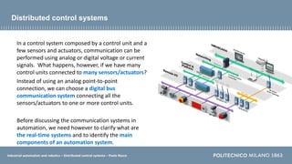
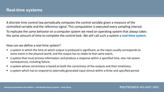
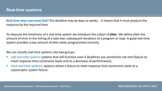
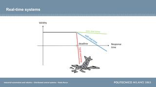
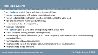
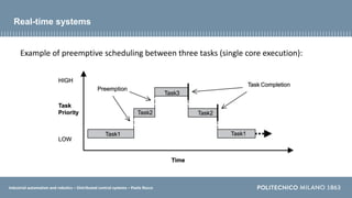
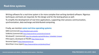
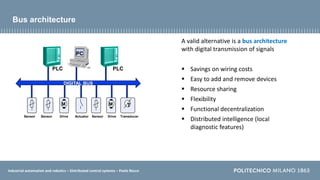
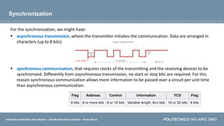
Industrial automation and robotics
Distributed control systems
Prof. Paolo Rocco (paolo.rocco@polimi.it)
Politecnico di Milano, Dipartimento di Elettronica, Informazione e Bioingegneria
Industrial automation and robotics – Distributed control systems – Paolo Rocco
Distributed control systems
In a control system composed by a control unit and a
few sensors and actuators, communication can be
performed using analog or digital voltage or current
signals. What happens, however, if we have many
control units connected to many sensors/actuators?
Instead of using an analog point-to-point
connection, we can choose a digital bus
communication system connecting all the
sensors/actuators to one or more control units.
Before discussing the communication systems in
automation, we need however to clarify what are
the real-time systems and to identify the main
components of an automation system.
Industrial automation and robotics – Distributed control systems – Paolo Rocco
A discrete time control law periodically computes the control variable given a measure of the
controlled variable and the reference signal. This computation is executed every sampling interval.
To replicate the same behavior on a computer system we need an operating system that always takes
the same amount of time to complete the control task. We will call such a system a real-time system.
How can we define a real-time system?
 a system in which the time at which output is produced is significant, as the input usually corresponds to
some event in the physical world, and the output has to relate to that same event;
 a system that must process information and produce a response within a specified time, else risk severe
consequences, including failure;
 a system whose correctness is based on both the correctness of the outputs and their timeliness;
 a system which has to respond to externally generated input stimuli within a finite and specified period.
Real-time systems
Industrial automation and robotics – Distributed control systems – Paolo Rocco
Real-time does not mean fast! The deadline may be days or weeks... it means that it must produce the
response by the required time.
To measure the timeliness of a real-time system we introduce the notion of jitter. We define jitter the
amount of error in the timing of a task over subsequent iterations of a program or loop. A good real-time
system provides a low amount of jitter when programmed correctly.
We can classify real-time systems into two groups:
 soft real-time system: systems that still function even if deadlines are sometimes not met (failure to
meet response time constraints leads only to a decrease of performance);
 hard real-time systems: systems where a failure to meet response time constraints leads to a
catastrophic system failure.
Real-time systems
Industrial automation and robotics – Distributed control systems – Paolo Rocco
Real-time systems
Response
time
Validity
deadline
Industrial automation and robotics – Distributed control systems – Paolo Rocco
From a hardware point of view, a real-time system should have:
 one or more processors with suitable computational power;
 known and predictable instruction execution time (at least for the worst case)
 low and deterministic memory and I/O latency;
 automatic fault detection capabilities;
 hardware redundancy.
From a software point of view, a real-time operating system should have:
 a task scheduler allowing different process priorities;
 a multitasking pre-emptive scheduler (a task can be temporarily interrupted and later resumed) allowing
context switches;
 techniques to avoid deadlock conditions;
 mechanisms to support inter-process communication and process synchronization;
 mechanisms to handle interrupts.
Real-time systems
Industrial automation and robotics – Distributed control systems – Paolo Rocco
Example of preemptive scheduling between three tasks (single core execution):
Real-time systems
Industrial automation and robotics – Distributed control systems – Paolo Rocco
Real-time systems
Writing software for a real-time system is far more complex than writing standard software. Rigorous
techniques and tools are required, for the design and for the testing phase as well.
To simplify the development of real-time applications, supporting inter-process communication,
synchronization, data exchange and distributed computing.
Finally, we mention some real-time operating systems:
QNX (commercial) https://blackberry.qnx.com/en
VxWorks (commercial) https://www.windriver.com/products/vxworks
WindowsCE (commercial) https://en.wikipedia.org/wiki/Windows_Embedded_Compact
RTAI (open), developed at POLIMI https://www.rtai.org
Xenomai (open) https://www.xenomai.org
Wind River Linux (open) https://www.windriver.com/products/linux/
Industrial automation and robotics – Distributed control systems – Paolo Rocco
The automation pyramid
As already mentioned, the automation and
control systems in an enterprise are
organized in a hierarchy (automation or
CIM pyramid).
We have already discussed PIDs and PLCs.
We will now take a quick look at other
elements.
Source:G. Kyprianidis
Industrial automation and robotics – Distributed control systems – Paolo Rocco
DCS
A distributed control system (DCS) is a
platform for automated control and
operation of a plant or industrial process. A
DCS combines the following into a single
automated system: human machine
interface (HMI), logic solvers, historian,
common database, alarm management,
and a common engineering suite.
Source: electrical technology
Industrial automation and robotics – Distributed control systems – Paolo Rocco
SCADA
A supervisory control and data acquisition
(SCADA) is a system of software and
hardware elements that allows industrial
organizations to:
 Control industrial processes locally or at
remote locations
 Monitor, gather, and process real-time
data
 Directly interact with devices such as
sensors, valves, pumps, motors, and
more through human-machine
interface (HMI) software
 Record events into a log file
Source: pmi
Industrial automation and robotics – Distributed control systems – Paolo Rocco
MES
A manufacturing execution system, or
MES, is a comprehensive, dynamic
software system that monitors, tracks,
documents, and controls the process of
manufacturing goods from raw materials
to finished products.
Providing a functional layer between
enterprise resource planning (ERP) and
process control systems, a MES gives
decision-makers the data to make the
plant floor more efficient and optimize
production.
Source: Syek
Industrial automation and robotics – Distributed control systems – Paolo Rocco
ERP
An enterprise resource planning, ERP,
efficiently manages in an integrated system
all the core business processes needed to
run a company: finance, HR,
manufacturing, supply chain, services,
procurement, and others.
ERP are delivered mostly via the cloud and
use the latest technologies, such as
artificial intelligence (AI) and machine
learning, to provide intelligent automation.
Source: SAP
Industrial automation and robotics – Distributed control systems – Paolo Rocco
Automation systems and networks
All the automation systems in a
company need to be connected
through networks.
Different levels in the automation
pyramid need different networks,
with different specifications (amount
of data, real-time specifications,
etc.)
A broad distinction can be made
between OT (Operational
Technology) networks and IT
(Information Technology) networks.
Source: Siemens
Industrial automation and robotics – Distributed control systems – Paolo Rocco
Drive Actuator
Sensor
Drive
Sensor
M
M
Let’s then consider the connection
between components of an
automation system.
In the simplest case of a control
system hardware architecture, two
“field” components, a transducer and
an actuator, are connected to the
controller, with analog connections
(current or voltage).
Sensorr Drive
M
How are the connections
organized if there are
numerous field components?
Point-to-point connections
Industrial automation and robotics – Distributed control systems – Paolo Rocco
Controller
Drive
Actuator
Sensor
Drive
Sensor
M
M
One possibility is a centralized
architecture with analogue point-
to-point connections.
However:
 High number of connections
 Cost of wiring
 High sensitivity to disturbances
(need for shielding)
 Poor flexibility and scalability
Traditional centralized architecture
Industrial automation and robotics – Distributed control systems – Paolo Rocco
PLC
DIGITAL BUS
Drive Actuator Transducer
Sensor Sensor Drive
PC
Sensor
M M T
PLC
A valid alternative is a bus architecture
with digital transmission of signals
 Savings on wiring costs
 Easy to add and remove devices
 Resource sharing
 Flexibility
 Functional decentralization
 Distributed intelligence (local
diagnostic features)
Bus architecture
Industrial automation and robotics – Distributed control systems – Paolo Rocco
Communication protocol
For the transmission of simple digital data
(e.g. bits) Simple digital I/O can be used:
0-5 volts transistor-transistor (TTL) logic (used e.g. in
Arduino)
0-3.3 volts for general purpose I/O (GPIO) logic (used e.g.
by Raspberry Pi)
0-10 or 0-24 volts (commonly used in PLC)
For the transmission of complex
information more sophisticated
communication mechanisms are required.
To standardize the communication we
need to define communication protocols.
000….1
Industrial automation and robotics – Distributed control systems – Paolo Rocco
Protocols are organized in a hierarchical way in a protocol stack. In this way each protocol leverages the
services of the protocol below it.
A conceptual model that standardizes the communication functions of a communication network,
without regard to their underlying internal structure and technology, is the Open Systems Interconnection
model (OSI model). The model partitions a communication system into seven abstraction layers. A layer
serves the layer above it and is served by the layer below it.
The model is a product of the Open Systems Interconnection project at the International Organization for
Standardization (ISO), maintained by the ISO/IEC 7498-1 standard.
ISO-OSI communication protocol
Industrial automation and robotics – Distributed control systems – Paolo Rocco
ISO-OSI communication protocol
Application: High-level APIs, including resource sharing, remote file
access, directory services and virtual terminals.
Presentation: Translation of data between a networking service and an application;
including character encoding, data compression and encryption/decryption.
Session: Managing communication sessions, i.e. continuous exchange of information in
the form of multiple back-and- forth transmissions between two nodes.
Transport: Reliable transmission of data segments between points on a network,
including segmentation, acknowledgement and multiplexing.
Network: Structuring and managing a multi-node network, including
addressing, routing and traffic control.
Data link: Reliable transmission of data frames between two nodes
connected by a physical layer.
Physical: Transmission and reception of raw bit streams over a
physical medium.
Not all the seven layers need to be implemented. In control systems the most used levels are:
physical, data link and application.
Industrial automation and robotics – Distributed control systems – Paolo Rocco
ISO-OSI and internet
How do the levels of the
ISO/OSI model map on
the internet?
Industrial automation and robotics – Distributed control systems – Paolo Rocco
Physical layer
The physical layer of a transmission protocol defines
 the electrical and physical specifications of the data including:
1. cable specifications (twisted, coaxial, optical fiber, …)
2. the layout of pins (number and mechanical specification of the connectors)
3. voltages and line impedance,
4. frequency (5 GHz or 2.4 GHz etc.) for wireless devices
 the encoding modality (NRZ, RZ, Manchester, …)
 the transmission mode (simplex, half duplex, full duplex) and the
type of the transmission (synchronous vs. asynchronous)
 the network topology
Industrial automation and robotics – Distributed control systems – Paolo Rocco
Transmission media
twisted pair wires
– two conductors twisted together for the purpose of canceling
out electromagnetic interference
– can be shielded (STP) or unshielded (UTP)
– mid-high speed (up to 100 Mbps in local area networks)
coaxial cables
– an inner conductor surrounded by a tubular insulating layer,
surrounded by a tubular conducting shield
– mid-high speed (up to 100 Mbps in local area networks)
optical fibers
– transparent fiber made by drawing glass (silica) or plastic
to a diameter slightly thicker than that of a human hair
– permits transmission over longer distances and at
higher bandwidths (up to 10 Gbps or more)
Industrial automation and robotics – Distributed control systems – Paolo Rocco
Line coding
Bits are transmitted through the physical medium using a line code.
Line coding consists of representing the digital signal to be transported, by a waveform that is optimally
tuned for the specific properties of the physical channel. The common types of line encoding are:
non-return-to-zero (NRZ), is a binary code in which
ones are represented by a positive voltage, while zeros
are represented by a negative voltage
return-to-zero (RZ), the signal drops (returns) to
zero between each bit
Manchester, the encoding of each data bit is either
low then high, or high then low, of equal time (the signal
is self-clocking)
Industrial automation and robotics – Distributed control systems – Paolo Rocco
Line coding
Bits can be alternatively transmitted through the physical medium using frequency modulation
techniques.
For example the HART protocol uses the FSK method
(Frequency Shift Keying) to encode bits.
The two digital values “0” and “1” are assigned
to the following frequencies:
logical “0”, 1200 Hz sinusoidal signal
logical “1”, 2200 Hz sinusoidal signal
Industrial automation and robotics – Distributed control systems – Paolo Rocco
Transmission mode
As for the transmission mode we might have:
 simplex, data can be sent only through one direction (unidirectional communication)
 half duplex, data can be sent in both directions but it is done one at a time (when the sender is
sending data, then at that time the receiver cannot send the sender a message)
 full duplex, data can be sent in both directions simultaneously (bidirectional communication)
Almost all current equipment is, on a physical level, prepared for full duplex transmission.
However, protocols can limit transmission to half duplex mode.
Industrial automation and robotics – Distributed control systems – Paolo Rocco
Synchronization
For the synchronization, we might have:
 asynchronous transmission, where the transmitter initiates the communication. Data are arranged in
characters (up to 8 bits)
 synchronous communication, that requires clocks of the transmitting and the receiving devices to be
synchronized. Differently from asynchronous transmission, no start or stop bits are required. For this
reason synchronous communication allows more information to be passed over a circuit per unit time
than asynchronous communication.
Industrial automation and robotics – Distributed control systems – Paolo Rocco
Data link layer
The data link layer:
 provides node-to-node data transfer, and detects and possibly corrects errors that
may occur in the physical layer
 defines the protocol to establish and terminate a connection between two physically
connected devices
 defines the protocol for flow control between them
Standard IEEE 802 further divides the data link layer into two sub-layers:
– Medium Access Control (MAC) layer, responsible for controlling how devices in a
network gain access to medium
– Logical Link Control (LLC) layer, responsible for identifying
Network layer protocols, controlling for errors and frame synchronization
Industrial automation and robotics – Distributed control systems – Paolo Rocco
Medium access control
The MAC sublayer provides addressing and channel access control mechanisms that make it possible for
several terminals or network nodes to communicate within a multiple access network that incorporates a
shared medium.
Examples of common multiple access protocols for wired networks are:
 CSMA/CD (defined by IEEE 802.3)
 Token bus (IEEE 802.4)
 Token ring (IEEE 802.5)
 Token passing (used in Fiber Distributed Data Interface, FDDI)
Industrial automation and robotics – Distributed control systems – Paolo Rocco
Medium access control
Carrier Sense Multiple Access with Collision Detection (CSMA/CD)
 if the medium is idle any node can start a transmission at any time
 the transmitter monitors for collisions during transmission and, if a collision is detected,
the frame is transmitted again
 not suitable for real-time applications as no bound on the transmission delay exists (due
to the retransmission mechanism)
Token bus/token ring/token passing
 uses a special frame called a “token” that travels around a logical “ring”
 token passing is a channel access method providing fair access for all nodes, and
eliminating the collision problem
 there can be master and slave nodes (slave nodes transmit only when asked by a master
node)
 access is deterministic hence suitable for real-time applications
Industrial automation and robotics – Distributed control systems – Paolo Rocco
The fieldbus
In modern distributed control systems, many standardized protocols are adopted, that are
identified as fieldbus. We will see some of them:
 CanBUS, DeviceNet, CanOPEN
 Profibus
 Ethernet, EtherCat
 ProfiNet
Industrial automation and robotics – Distributed control systems – Paolo Rocco
CANbus
CANbus (Controller Area Network bus) has been developed at Robert Bosch GmbH and
released in 1986 and represents the standard communication protocol in automotive.
Today, it is also adopted in non-automotive
application, though in a slightly modified manner
(DeviceNet and CANopen).
Industrial automation and robotics – Distributed control systems – Paolo Rocco
CANbus
Feature (physical level) Adopted value in CANbus
Transmission media shielded twisted pairs (STP)
Transmission speed from 125 kbps up to 1 Mbps (up to 40 m)
Line encoding non-return-to-zero (NRZ)
Synchronization type asynchronous (with clock synchronization to avoid bit slips)
Feature (data link level) Adopted value in CANbus
MAC type ad hoc arbitration based on priority frames
Industrial automation and robotics – Distributed control systems – Paolo Rocco
CANbus: example of arbitration for the access to the bus
Industrial automation and robotics – Distributed control systems – Paolo Rocco
ProfiBus
ProfiBus (Process Field Bus) is a standard for fieldbus communication in automation technology and was
first promoted in 1989 by BMBF (German department of education and research) and then used by
Siemens.
There are two versions
ProfiBus DP (Decentralized Peripherals) is used to operate sensors and actuators via a centralized
controller in production (factory) automation applications
ProfiBus PA (Process Automation) is used to monitor measuring equipment via a process control system
in process automation applications
Industrial automation and robotics – Distributed control systems – Paolo Rocco
ProfiBus
Feature (physical level) Adopted value in ProfiBus-DP
Transmission media shielded twisted (STP) pairs or fiber optics
Transmission speed up 12 Mbps (up to 1.2 km)
Line encoding Manchester (Manchester encoding Bus Powered, MBP)
Synchronization type synchronous
Feature (data link level) Adopted value in ProfiBus-DP
MAC type Token-ring master and passive slave devices
Industrial automation and robotics – Distributed control systems – Paolo Rocco
ProfiBus-DP: access to the bus
PLC
PROFIBUS
“active stations”, “master devices”
Drive Acturator Transmitter
“passive stations”, “slave devices”
Sensor Sensor Drive
Logical network with token ring among master stations
PC
Sensor
M M T
PLC
Industrial automation and robotics – Distributed control systems – Paolo Rocco
Ethernet
Ethernet was developed at Xerox PARC between 1973 and 1974 and is a family of computer networking
technologies commonly used in local area networks (LAN), metropolitan area networks (MAN) and wide
area networks (WAN).
It has been first standardized in 1983 as IEEE 802.3 and has since been refined to support higher bit rates
and longer link distances.
Over time, Ethernet has largely replaced competing wired LAN technologies. Thought Ethernet is not
meant to allow for real-time communication, other protocols have been developed on this standard.
Industrial automation and robotics – Distributed control systems – Paolo Rocco
Ethernet
Feature (physical level) Adopted value in Ethernet
Transmission media unshielded twisted pairs (UTP), coaxial, or fiber optics
Transmission speed up 1 Gbps (up to 2 km)
Line encoding Manchester
Feature (data link level) Adopted value in Ethernet
MAC type CSMA/CD
Industrial automation and robotics – Distributed control systems – Paolo Rocco
Industrial Ethernet
Different protocols exist that make Ethernet suitable for a real-time fieldbus
communication system:
PROFINET (Process Field Net) is an industry technical standard for data
communication over Industrial Ethernet, with a particular strength in delivering
data under hard real-time constraints (≤ 1 ms). The standard is maintained and
supported by Profibus & Profinet International.
EtherCAT (Ethernet for Control Automation Technology) is an Ethernet-
based fieldbus system, invented by Beckhoff Automation. The protocol is
suitable for both hard and soft real-time computing requirements

Distributed control systems.pdfffffffffff

  • 1.
    Industrial automation androbotics Distributed control systems Prof. Paolo Rocco (paolo.rocco@polimi.it) Politecnico di Milano, Dipartimento di Elettronica, Informazione e Bioingegneria
  • 2.
    Industrial automation androbotics – Distributed control systems – Paolo Rocco Distributed control systems In a control system composed by a control unit and a few sensors and actuators, communication can be performed using analog or digital voltage or current signals. What happens, however, if we have many control units connected to many sensors/actuators? Instead of using an analog point-to-point connection, we can choose a digital bus communication system connecting all the sensors/actuators to one or more control units. Before discussing the communication systems in automation, we need however to clarify what are the real-time systems and to identify the main components of an automation system.
  • 3.
    Industrial automation androbotics – Distributed control systems – Paolo Rocco A discrete time control law periodically computes the control variable given a measure of the controlled variable and the reference signal. This computation is executed every sampling interval. To replicate the same behavior on a computer system we need an operating system that always takes the same amount of time to complete the control task. We will call such a system a real-time system. How can we define a real-time system?  a system in which the time at which output is produced is significant, as the input usually corresponds to some event in the physical world, and the output has to relate to that same event;  a system that must process information and produce a response within a specified time, else risk severe consequences, including failure;  a system whose correctness is based on both the correctness of the outputs and their timeliness;  a system which has to respond to externally generated input stimuli within a finite and specified period. Real-time systems
  • 4.
    Industrial automation androbotics – Distributed control systems – Paolo Rocco Real-time does not mean fast! The deadline may be days or weeks... it means that it must produce the response by the required time. To measure the timeliness of a real-time system we introduce the notion of jitter. We define jitter the amount of error in the timing of a task over subsequent iterations of a program or loop. A good real-time system provides a low amount of jitter when programmed correctly. We can classify real-time systems into two groups:  soft real-time system: systems that still function even if deadlines are sometimes not met (failure to meet response time constraints leads only to a decrease of performance);  hard real-time systems: systems where a failure to meet response time constraints leads to a catastrophic system failure. Real-time systems
  • 5.
    Industrial automation androbotics – Distributed control systems – Paolo Rocco Real-time systems Response time Validity deadline
  • 6.
    Industrial automation androbotics – Distributed control systems – Paolo Rocco From a hardware point of view, a real-time system should have:  one or more processors with suitable computational power;  known and predictable instruction execution time (at least for the worst case)  low and deterministic memory and I/O latency;  automatic fault detection capabilities;  hardware redundancy. From a software point of view, a real-time operating system should have:  a task scheduler allowing different process priorities;  a multitasking pre-emptive scheduler (a task can be temporarily interrupted and later resumed) allowing context switches;  techniques to avoid deadlock conditions;  mechanisms to support inter-process communication and process synchronization;  mechanisms to handle interrupts. Real-time systems
  • 7.
    Industrial automation androbotics – Distributed control systems – Paolo Rocco Example of preemptive scheduling between three tasks (single core execution): Real-time systems
  • 8.
    Industrial automation androbotics – Distributed control systems – Paolo Rocco Real-time systems Writing software for a real-time system is far more complex than writing standard software. Rigorous techniques and tools are required, for the design and for the testing phase as well. To simplify the development of real-time applications, supporting inter-process communication, synchronization, data exchange and distributed computing. Finally, we mention some real-time operating systems: QNX (commercial) https://blackberry.qnx.com/en VxWorks (commercial) https://www.windriver.com/products/vxworks WindowsCE (commercial) https://en.wikipedia.org/wiki/Windows_Embedded_Compact RTAI (open), developed at POLIMI https://www.rtai.org Xenomai (open) https://www.xenomai.org Wind River Linux (open) https://www.windriver.com/products/linux/
  • 9.
    Industrial automation androbotics – Distributed control systems – Paolo Rocco The automation pyramid As already mentioned, the automation and control systems in an enterprise are organized in a hierarchy (automation or CIM pyramid). We have already discussed PIDs and PLCs. We will now take a quick look at other elements. Source:G. Kyprianidis
  • 10.
    Industrial automation androbotics – Distributed control systems – Paolo Rocco DCS A distributed control system (DCS) is a platform for automated control and operation of a plant or industrial process. A DCS combines the following into a single automated system: human machine interface (HMI), logic solvers, historian, common database, alarm management, and a common engineering suite. Source: electrical technology
  • 11.
    Industrial automation androbotics – Distributed control systems – Paolo Rocco SCADA A supervisory control and data acquisition (SCADA) is a system of software and hardware elements that allows industrial organizations to:  Control industrial processes locally or at remote locations  Monitor, gather, and process real-time data  Directly interact with devices such as sensors, valves, pumps, motors, and more through human-machine interface (HMI) software  Record events into a log file Source: pmi
  • 12.
    Industrial automation androbotics – Distributed control systems – Paolo Rocco MES A manufacturing execution system, or MES, is a comprehensive, dynamic software system that monitors, tracks, documents, and controls the process of manufacturing goods from raw materials to finished products. Providing a functional layer between enterprise resource planning (ERP) and process control systems, a MES gives decision-makers the data to make the plant floor more efficient and optimize production. Source: Syek
  • 13.
    Industrial automation androbotics – Distributed control systems – Paolo Rocco ERP An enterprise resource planning, ERP, efficiently manages in an integrated system all the core business processes needed to run a company: finance, HR, manufacturing, supply chain, services, procurement, and others. ERP are delivered mostly via the cloud and use the latest technologies, such as artificial intelligence (AI) and machine learning, to provide intelligent automation. Source: SAP
  • 14.
    Industrial automation androbotics – Distributed control systems – Paolo Rocco Automation systems and networks All the automation systems in a company need to be connected through networks. Different levels in the automation pyramid need different networks, with different specifications (amount of data, real-time specifications, etc.) A broad distinction can be made between OT (Operational Technology) networks and IT (Information Technology) networks. Source: Siemens
  • 15.
    Industrial automation androbotics – Distributed control systems – Paolo Rocco Drive Actuator Sensor Drive Sensor M M Let’s then consider the connection between components of an automation system. In the simplest case of a control system hardware architecture, two “field” components, a transducer and an actuator, are connected to the controller, with analog connections (current or voltage). Sensorr Drive M How are the connections organized if there are numerous field components? Point-to-point connections
  • 16.
    Industrial automation androbotics – Distributed control systems – Paolo Rocco Controller Drive Actuator Sensor Drive Sensor M M One possibility is a centralized architecture with analogue point- to-point connections. However:  High number of connections  Cost of wiring  High sensitivity to disturbances (need for shielding)  Poor flexibility and scalability Traditional centralized architecture
  • 17.
    Industrial automation androbotics – Distributed control systems – Paolo Rocco PLC DIGITAL BUS Drive Actuator Transducer Sensor Sensor Drive PC Sensor M M T PLC A valid alternative is a bus architecture with digital transmission of signals  Savings on wiring costs  Easy to add and remove devices  Resource sharing  Flexibility  Functional decentralization  Distributed intelligence (local diagnostic features) Bus architecture
  • 18.
    Industrial automation androbotics – Distributed control systems – Paolo Rocco Communication protocol For the transmission of simple digital data (e.g. bits) Simple digital I/O can be used: 0-5 volts transistor-transistor (TTL) logic (used e.g. in Arduino) 0-3.3 volts for general purpose I/O (GPIO) logic (used e.g. by Raspberry Pi) 0-10 or 0-24 volts (commonly used in PLC) For the transmission of complex information more sophisticated communication mechanisms are required. To standardize the communication we need to define communication protocols. 000….1
  • 19.
    Industrial automation androbotics – Distributed control systems – Paolo Rocco Protocols are organized in a hierarchical way in a protocol stack. In this way each protocol leverages the services of the protocol below it. A conceptual model that standardizes the communication functions of a communication network, without regard to their underlying internal structure and technology, is the Open Systems Interconnection model (OSI model). The model partitions a communication system into seven abstraction layers. A layer serves the layer above it and is served by the layer below it. The model is a product of the Open Systems Interconnection project at the International Organization for Standardization (ISO), maintained by the ISO/IEC 7498-1 standard. ISO-OSI communication protocol
  • 20.
    Industrial automation androbotics – Distributed control systems – Paolo Rocco ISO-OSI communication protocol Application: High-level APIs, including resource sharing, remote file access, directory services and virtual terminals. Presentation: Translation of data between a networking service and an application; including character encoding, data compression and encryption/decryption. Session: Managing communication sessions, i.e. continuous exchange of information in the form of multiple back-and- forth transmissions between two nodes. Transport: Reliable transmission of data segments between points on a network, including segmentation, acknowledgement and multiplexing. Network: Structuring and managing a multi-node network, including addressing, routing and traffic control. Data link: Reliable transmission of data frames between two nodes connected by a physical layer. Physical: Transmission and reception of raw bit streams over a physical medium. Not all the seven layers need to be implemented. In control systems the most used levels are: physical, data link and application.
  • 21.
    Industrial automation androbotics – Distributed control systems – Paolo Rocco ISO-OSI and internet How do the levels of the ISO/OSI model map on the internet?
  • 22.
    Industrial automation androbotics – Distributed control systems – Paolo Rocco Physical layer The physical layer of a transmission protocol defines  the electrical and physical specifications of the data including: 1. cable specifications (twisted, coaxial, optical fiber, …) 2. the layout of pins (number and mechanical specification of the connectors) 3. voltages and line impedance, 4. frequency (5 GHz or 2.4 GHz etc.) for wireless devices  the encoding modality (NRZ, RZ, Manchester, …)  the transmission mode (simplex, half duplex, full duplex) and the type of the transmission (synchronous vs. asynchronous)  the network topology
  • 23.
    Industrial automation androbotics – Distributed control systems – Paolo Rocco Transmission media twisted pair wires – two conductors twisted together for the purpose of canceling out electromagnetic interference – can be shielded (STP) or unshielded (UTP) – mid-high speed (up to 100 Mbps in local area networks) coaxial cables – an inner conductor surrounded by a tubular insulating layer, surrounded by a tubular conducting shield – mid-high speed (up to 100 Mbps in local area networks) optical fibers – transparent fiber made by drawing glass (silica) or plastic to a diameter slightly thicker than that of a human hair – permits transmission over longer distances and at higher bandwidths (up to 10 Gbps or more)
  • 24.
    Industrial automation androbotics – Distributed control systems – Paolo Rocco Line coding Bits are transmitted through the physical medium using a line code. Line coding consists of representing the digital signal to be transported, by a waveform that is optimally tuned for the specific properties of the physical channel. The common types of line encoding are: non-return-to-zero (NRZ), is a binary code in which ones are represented by a positive voltage, while zeros are represented by a negative voltage return-to-zero (RZ), the signal drops (returns) to zero between each bit Manchester, the encoding of each data bit is either low then high, or high then low, of equal time (the signal is self-clocking)
  • 25.
    Industrial automation androbotics – Distributed control systems – Paolo Rocco Line coding Bits can be alternatively transmitted through the physical medium using frequency modulation techniques. For example the HART protocol uses the FSK method (Frequency Shift Keying) to encode bits. The two digital values “0” and “1” are assigned to the following frequencies: logical “0”, 1200 Hz sinusoidal signal logical “1”, 2200 Hz sinusoidal signal
  • 26.
    Industrial automation androbotics – Distributed control systems – Paolo Rocco Transmission mode As for the transmission mode we might have:  simplex, data can be sent only through one direction (unidirectional communication)  half duplex, data can be sent in both directions but it is done one at a time (when the sender is sending data, then at that time the receiver cannot send the sender a message)  full duplex, data can be sent in both directions simultaneously (bidirectional communication) Almost all current equipment is, on a physical level, prepared for full duplex transmission. However, protocols can limit transmission to half duplex mode.
  • 27.
    Industrial automation androbotics – Distributed control systems – Paolo Rocco Synchronization For the synchronization, we might have:  asynchronous transmission, where the transmitter initiates the communication. Data are arranged in characters (up to 8 bits)  synchronous communication, that requires clocks of the transmitting and the receiving devices to be synchronized. Differently from asynchronous transmission, no start or stop bits are required. For this reason synchronous communication allows more information to be passed over a circuit per unit time than asynchronous communication.
  • 28.
    Industrial automation androbotics – Distributed control systems – Paolo Rocco Data link layer The data link layer:  provides node-to-node data transfer, and detects and possibly corrects errors that may occur in the physical layer  defines the protocol to establish and terminate a connection between two physically connected devices  defines the protocol for flow control between them Standard IEEE 802 further divides the data link layer into two sub-layers: – Medium Access Control (MAC) layer, responsible for controlling how devices in a network gain access to medium – Logical Link Control (LLC) layer, responsible for identifying Network layer protocols, controlling for errors and frame synchronization
  • 29.
    Industrial automation androbotics – Distributed control systems – Paolo Rocco Medium access control The MAC sublayer provides addressing and channel access control mechanisms that make it possible for several terminals or network nodes to communicate within a multiple access network that incorporates a shared medium. Examples of common multiple access protocols for wired networks are:  CSMA/CD (defined by IEEE 802.3)  Token bus (IEEE 802.4)  Token ring (IEEE 802.5)  Token passing (used in Fiber Distributed Data Interface, FDDI)
  • 30.
    Industrial automation androbotics – Distributed control systems – Paolo Rocco Medium access control Carrier Sense Multiple Access with Collision Detection (CSMA/CD)  if the medium is idle any node can start a transmission at any time  the transmitter monitors for collisions during transmission and, if a collision is detected, the frame is transmitted again  not suitable for real-time applications as no bound on the transmission delay exists (due to the retransmission mechanism) Token bus/token ring/token passing  uses a special frame called a “token” that travels around a logical “ring”  token passing is a channel access method providing fair access for all nodes, and eliminating the collision problem  there can be master and slave nodes (slave nodes transmit only when asked by a master node)  access is deterministic hence suitable for real-time applications
  • 31.
    Industrial automation androbotics – Distributed control systems – Paolo Rocco The fieldbus In modern distributed control systems, many standardized protocols are adopted, that are identified as fieldbus. We will see some of them:  CanBUS, DeviceNet, CanOPEN  Profibus  Ethernet, EtherCat  ProfiNet
  • 32.
    Industrial automation androbotics – Distributed control systems – Paolo Rocco CANbus CANbus (Controller Area Network bus) has been developed at Robert Bosch GmbH and released in 1986 and represents the standard communication protocol in automotive. Today, it is also adopted in non-automotive application, though in a slightly modified manner (DeviceNet and CANopen).
  • 33.
    Industrial automation androbotics – Distributed control systems – Paolo Rocco CANbus Feature (physical level) Adopted value in CANbus Transmission media shielded twisted pairs (STP) Transmission speed from 125 kbps up to 1 Mbps (up to 40 m) Line encoding non-return-to-zero (NRZ) Synchronization type asynchronous (with clock synchronization to avoid bit slips) Feature (data link level) Adopted value in CANbus MAC type ad hoc arbitration based on priority frames
  • 34.
    Industrial automation androbotics – Distributed control systems – Paolo Rocco CANbus: example of arbitration for the access to the bus
  • 35.
    Industrial automation androbotics – Distributed control systems – Paolo Rocco ProfiBus ProfiBus (Process Field Bus) is a standard for fieldbus communication in automation technology and was first promoted in 1989 by BMBF (German department of education and research) and then used by Siemens. There are two versions ProfiBus DP (Decentralized Peripherals) is used to operate sensors and actuators via a centralized controller in production (factory) automation applications ProfiBus PA (Process Automation) is used to monitor measuring equipment via a process control system in process automation applications
  • 36.
    Industrial automation androbotics – Distributed control systems – Paolo Rocco ProfiBus Feature (physical level) Adopted value in ProfiBus-DP Transmission media shielded twisted (STP) pairs or fiber optics Transmission speed up 12 Mbps (up to 1.2 km) Line encoding Manchester (Manchester encoding Bus Powered, MBP) Synchronization type synchronous Feature (data link level) Adopted value in ProfiBus-DP MAC type Token-ring master and passive slave devices
  • 37.
    Industrial automation androbotics – Distributed control systems – Paolo Rocco ProfiBus-DP: access to the bus PLC PROFIBUS “active stations”, “master devices” Drive Acturator Transmitter “passive stations”, “slave devices” Sensor Sensor Drive Logical network with token ring among master stations PC Sensor M M T PLC
  • 38.
    Industrial automation androbotics – Distributed control systems – Paolo Rocco Ethernet Ethernet was developed at Xerox PARC between 1973 and 1974 and is a family of computer networking technologies commonly used in local area networks (LAN), metropolitan area networks (MAN) and wide area networks (WAN). It has been first standardized in 1983 as IEEE 802.3 and has since been refined to support higher bit rates and longer link distances. Over time, Ethernet has largely replaced competing wired LAN technologies. Thought Ethernet is not meant to allow for real-time communication, other protocols have been developed on this standard.
  • 39.
    Industrial automation androbotics – Distributed control systems – Paolo Rocco Ethernet Feature (physical level) Adopted value in Ethernet Transmission media unshielded twisted pairs (UTP), coaxial, or fiber optics Transmission speed up 1 Gbps (up to 2 km) Line encoding Manchester Feature (data link level) Adopted value in Ethernet MAC type CSMA/CD
  • 40.
    Industrial automation androbotics – Distributed control systems – Paolo Rocco Industrial Ethernet Different protocols exist that make Ethernet suitable for a real-time fieldbus communication system: PROFINET (Process Field Net) is an industry technical standard for data communication over Industrial Ethernet, with a particular strength in delivering data under hard real-time constraints (≤ 1 ms). The standard is maintained and supported by Profibus & Profinet International. EtherCAT (Ethernet for Control Automation Technology) is an Ethernet- based fieldbus system, invented by Beckhoff Automation. The protocol is suitable for both hard and soft real-time computing requirements