This document summarizes a student's dissertation on the robustness of steel structures. It includes acknowledgments, contents, and an introduction. The introduction discusses the aims of investigating failures in steel structures through analyzing different design methods for robustness. It outlines objectives to examine the effects of robustness through member tying and alternative load paths, and to provide an overview of methodologies for quantifying catenary and membrane mechanisms. The document layout includes chapters on literature review, finite element method, modeling and analyzing simple and large 3D structures, and conclusions.
![Robustness of Steel Structures Syed Rizvi|1240894
5
Chapter 1 | Introduction
The research is an indoctrination of the different strategies involved in structural
engineering which ensure robustness in steel structures. Various incidents in
building structures leading to progressive collapse (term used to describe the
collapse of structures lacking Robustness) are discussed. These collapses will be
further discussed in detail in the literature review.
In order to gain a better understanding of the different aspects that are scrutinized
in the report, it is of utmost importance to define Robustness in its essence.
The definition of Robustness has not been precisely laid down to date [Uwe
Starossek]. Authors tend to use it differently in the discussions on progressive
collapse and there exists no general consensus.
Whenever a key element is removed it results in the load being transferred to other
elements which if not designed in accordance to the standards (each country has
its own set of standard regulations for ensuring robustness) of robustness would
result in a collapse of the structure.
The report does not only debate about different strategies for robustness but also
examines the different changes in regulations that were laid down by engineers
following the incidents of progressive collapse.
A range of structural collapses from the Ronan Point Collapse UK (1968) to the
World Trade centre USA (2001) have been review. The effect that these incidents
had on the building regulations in the respective countries is discussed.
It is known that engineers have always tried to make the life of people better and
safe by making certain that the infrastructure around us is improved over time. It is
this belief that in turn ensures that the new structures built are raised to a better
quality or standard over generations.
World Trade centre USA (2001) collapse, 33years after the Ronan Point Collapse
raises questions whether the standard of modern structures has significantly been
raised over the time or not. Throwing light on other constraints that would have
influenced this collapse can help arrive at a conclusion.](https://image.slidesharecdn.com/cbc42944-264e-4f32-8a90-056033ebe7a4-150617175605-lva1-app6891/75/Dissertation-6-2048.jpg)
![Robustness of Steel Structures Syed Rizvi|1240894
10
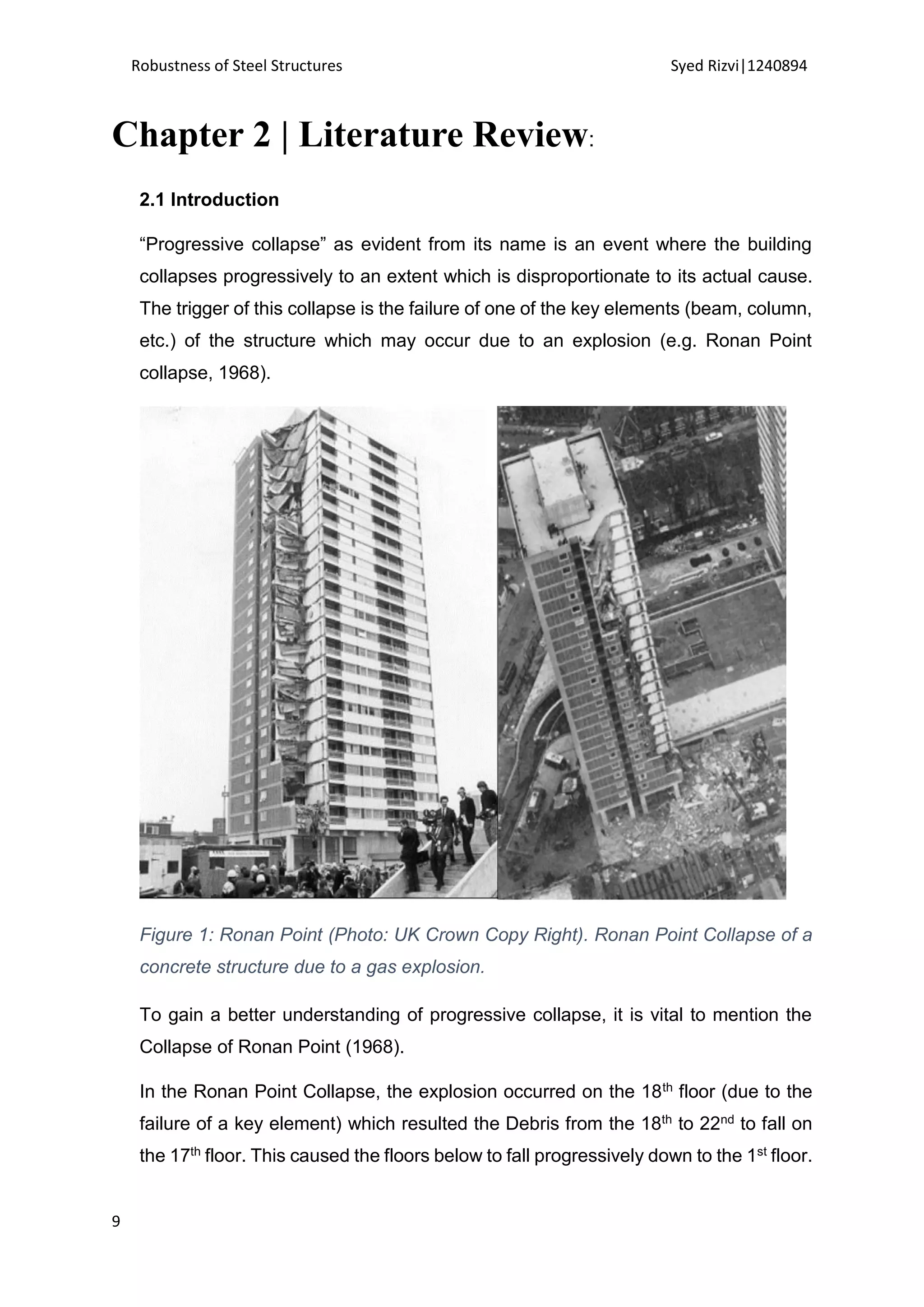
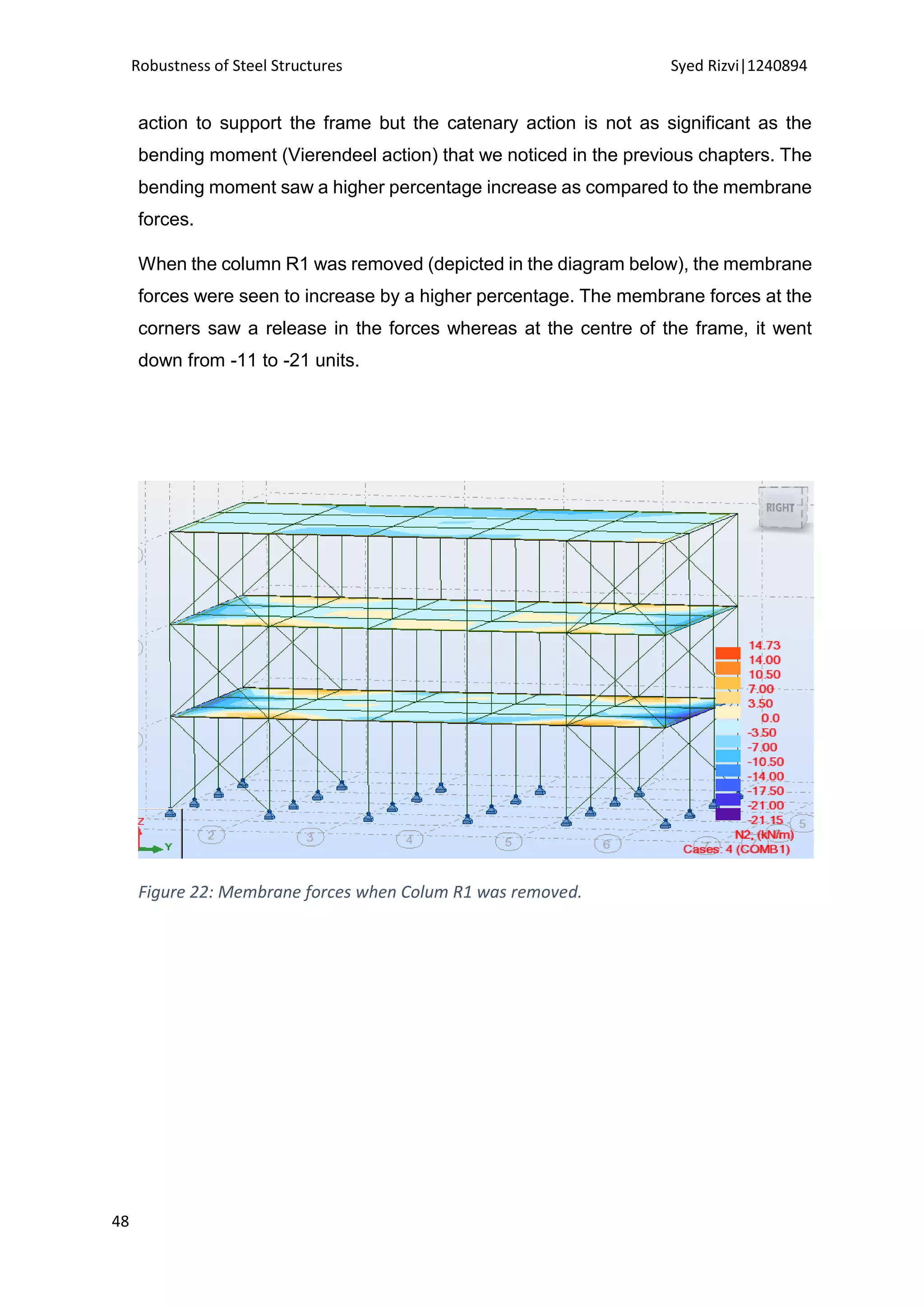
Therefore, “progressive collapse” can be defined as the disproportionate collapse
of an entire structure or large part of a structure, spreading from an initial local
failure from an element (column or beam) to another.
To prevent such collapse in the buildings, different measures were made to resist
progressive collapse.
EN 1991-1-7 of the Accidental Actions defined “robustness” as
“The ability of a structure to withstand events like fire, explosions, impact or the
consequences of human error, without being damaged to an extent
disproportionate to the original cause”.
‘Progressive collapse’ and ‘Robustness’ are two different things that should not be
confused together. While ‘progressive collapse’ is the issue that needs to be
tackled, ‘robustness’ forms the method in solving this complex issue by
safeguarding the buildings against progressive collapse.
Thus, robustness can also be defined as “collapse resistance” or
“unresponsiveness to local failure in the structure” [Uwe Starossek (2009)].
However, there are two approaches to understand this definition. It can be
understood quantitatively and qualitatively. Unresponsiveness/insensitivity and
local failure are not quantifiable by simple mathematics.
On a case-by-case study, they are more often used in the decision making process
which depends on the design objectives 3 and 4.
Design Objectives
1. Accidental actions (assumable)
2. Case of local failure (assumable)
3. Extent of collapse (acceptable).
4. Other acceptable damages.
5. Applicable partial safety factors and combinations of actions. [ 1]
1
[Uwe Starossek (2009)] “Progressive collapse of structures”.](https://image.slidesharecdn.com/cbc42944-264e-4f32-8a90-056033ebe7a4-150617175605-lva1-app6891/75/Dissertation-11-2048.jpg)
![Robustness of Steel Structures Syed Rizvi|1240894
11
In the decision making process, the design objectives have to be established in
advance which form the bases in defining robustness quantitatively.
In the same way ‘local failure’ equates to design objective 2, ‘collapse resistance’
can be equated to design objective 1 (assumable accidental actions). Design
objective 3 and 4 quantify insensitivity. When the DO 1 progresses to an
unacceptable total damage, a disproportionate collapse is said to have been
occurred.
The research aims to provide guidance on different design strategies for
robustness in buildings by carrying out a series of computational experiments in
relation to the constraints that may affect the design strategies.
2.2 Previous Research | Critical Review of Design guidelines
There have been many attempts of addressing the issue of progressive collapse
and much literature has been published in response to the catastrophic events that
have taken place. Ronan point collapse (1968), Skyline Tower in Virginia, USA,
(1973), attack on US barracks in Beirut(1983), Lebanon, Alfred P. Murrah Federal
Building(1995) and 9/11 World Trade Centre(2001 are some of the incidents of
progressive collpase which have ignited widespread research in regard to
progressive collapse avoidance.
In the UK, the first regulation changes were made after the Ronan Point Collapse
in 1968. A lot of research was started as a result of this incident to make clear the
much un-understood progressive collapse [The Structural Engineer, 1969; ISE,
1969].
Allen and Schriever [1972]
The UK building regulations introduced ‘Tying’ which would provide stability to
structural members in case of an untoward incident causing collapse. In the USA,
Allen and Schriever [1972] also did studies to address this complex issue. In their](https://image.slidesharecdn.com/cbc42944-264e-4f32-8a90-056033ebe7a4-150617175605-lva1-app6891/75/Dissertation-12-2048.jpg)
![Robustness of Steel Structures Syed Rizvi|1240894
12
research, a summary of events of progressive collapse that had taken place in
North America (US, Canada) between 1969 to1972 was presented.
Ellingwood [1978]
To reduce the risk of progressive collapse suitable design strategies were
discussed by Ellingwood [1978] using the probabilistic method. Gross [1983]
discussed his analytical model (2D computer-based) after he presented his studies
of progressive collapse. In this discussion, he has explained the Alternate Load
Path (ALP) method which is claimed can ensure robustness. The explanations
were based on his reported structural behaviour in response to the removal of
columns from different locations.
Pretlove [1991]
Pretlove [1991], examined the dynamic effects in progressive collapse. His
experiments showed that local failure (in an element) is capable of inducing
progressive fracture in some of the remaining elements/members. However, the
key factor that is to be noted here is the high probability of a fracture to take place
before a new equilibrium is established.
Owens and Moore [1992]
Abiding by the UK regulations, the tying forces induced in the steel connections
have to be resisted. Therefore, with the aim of inspecting the simple steel
connections’ capacity to the forces, Owens and Moore [1992] presented a series
of experimental data. This proved vital in providing help with design approaches
soon after.
Stefieck[1996]
In 1996, New York City Technology Center a six storey building saw Stefieck report
a methodology to protect the exterior of the building. The designer increased the
ductility of beam-column connection. The moment capacity, size of sprandels and
columns were also increased. This enabled the frame to redistribute the load to the
other undamaged parts of the structure in case of an exterior column being
removed ensuring a higher redundancy.](https://image.slidesharecdn.com/cbc42944-264e-4f32-8a90-056033ebe7a4-150617175605-lva1-app6891/75/Dissertation-13-2048.jpg)
![Robustness of Steel Structures Syed Rizvi|1240894
13
[Corley et al, 1998]
A few years after the Alfred P. Murrah Federal Building in the city of Okhlahama
Corley [Corley et al, 1998] investigated the damage caused by the explosion. He
aimed at determining the mechanism responsible for the failure of the structure.
Engineering strategies were reviewed to prvent such damage in the future whih
resulted in the Compartmentalised Construction of all the new Federal Buildings.
Dual System and Special Moment Frame were recommended to improve the
redundancy.
DOD [2002]
Due to the rise in the political influence of USA all over the world, the military and
defence agencies have become a target of violent attacks. In response to the threat
posed by growing attacks, the Department of Defence published a series of Unified
Facilities Criteria (UFC). The departments of the military, the defense agencies,
and Department of Defence field activities applied the series of UFC to design their
building facilities.
Buildings with 3 or more stories were considered to be in a higher risk of
progressive collapse by the UFC (DOD 2002). It is because the number of stories
in a building has a direct effect on the ‘chain reaction’ [Ellingwood and Leyendecker
1977].
Only one adjacent floor has the ability to collapse due to the loss of the local
element on the ground level when less than three stories are present. From this, it
can be inferred that less high structures may be proportionate to the initial failure
which triggers the event.
“…Design the superstructure to sustain local damage with the structural system as
a whole remaining stable and not being damaged to an extent disproportionate to
the original local damage” is the general statement used in the document (DOD
2002) to prevent from progressive collapse.
The framing system should assure adequate levels of continuity, redundancy (for
load paths) as well as the provision of energy dissipating potential to accomplish
the requirements.](https://image.slidesharecdn.com/cbc42944-264e-4f32-8a90-056033ebe7a4-150617175605-lva1-app6891/75/Dissertation-14-2048.jpg)
![Robustness of Steel Structures Syed Rizvi|1240894
17
Therefore, it can be inferred that a distinguished lack of inherent structural
robustness in buildings has been addressed.
2.4.2 Integrity | ACI Methodology
The Ronan Point UK building (see details of collapse chapter 2.1) that saw a
progressive collapse in 1968 was mainly consisted of pre-caste concrete structure.
Due to its pre-caste concrete build, it relied heavily on gravity loads and bond and
sparked high interest in the concrete industry to get involved in robustness and
collapse resistance [Popoff 1975].
The American Concrete Institute building code requirements explained the
reinforcement and connections in detail stating that tying of structural members
effectively would ensure integrity/robustness for the overall system. This would
further go on to set the standard of minimum requirements in concrete framed
structures providing minimum level of structural integrity. The intention was to
confine or minimise the damage resulting from a failure of a key element, within a
relatively small area by improving redundancy and ductility. This would give the
structure a better chance to ensure its stability.
2.4.3 Structural Integrity | ASCE Provisions
“Minimum Design Loads for Buildings and Other Structures (ASCE 2010)” a
publication by ASCE gives general guidance on providing structural integrity.
Allowance of the forces and moments to transfer between members helps provide
a continuous load path as intended by the provisions.
In its commentary, the ASCE considers the safety of public. It discusses the
structures housing higher number of people which may be a subject of attack and
states that “….more rigorous protection should be incorporated into designs than
provided by these (above mention) sections.”
The definition of untoward incidents should be considered at design stages. ASCE
does not take the responsibility of defining these events.
Two design methods for robustness that have been discussed in the commentary
are the direct and the indirect methods.](https://image.slidesharecdn.com/cbc42944-264e-4f32-8a90-056033ebe7a4-150617175605-lva1-app6891/75/Dissertation-18-2048.jpg)
![Robustness of Steel Structures Syed Rizvi|1240894
18
2.4.4 Unified Facilities Criteria
Owing to the growing risk of terrorist threats Department of Defense (DoD) and
Department of Defense (GSA) formed guidelines for resisting collapse due to
explosions. The guidelines were provided in the form of the Unified Facilities
Criteria (UFC) 4-023-03 Design of Buildings to Resist Progressive Collapse (DOD
2005).
This document is a generic guide providing information in issues related to
robustness of structures. To quote an example, the redistribution of loads from a
damaged part of the structure to other undamaged parts by the use of tie forces
has been talked about.
Analysis of alternate load paths in a structure and use of amplification factors when
designing structures is also provided.
2.5 Progressive Collapse | Review of Significant Collapses
Consultation to the literature of historical events can lead to a better understanding
of the mechanism of progressive collapse. The following are the few but more
important incidents of progressive collapse which have occurred in the last 5
decades. The investigation of the causes of such collapses helps to get a better
understanding of the mechanism of “progressive collapse”.
All the three mentioned buildings have suffered progressive collapse.
The research makes an attempt to investigate the cause and mechanism of the
collapse by providing a critical analysis of all the constraints related to progressive
collapse. Special attention is given to the causes of the collapse of the World Trade
Centre (2001) which paved way for further research in this field (presented in
section 2.5.2).
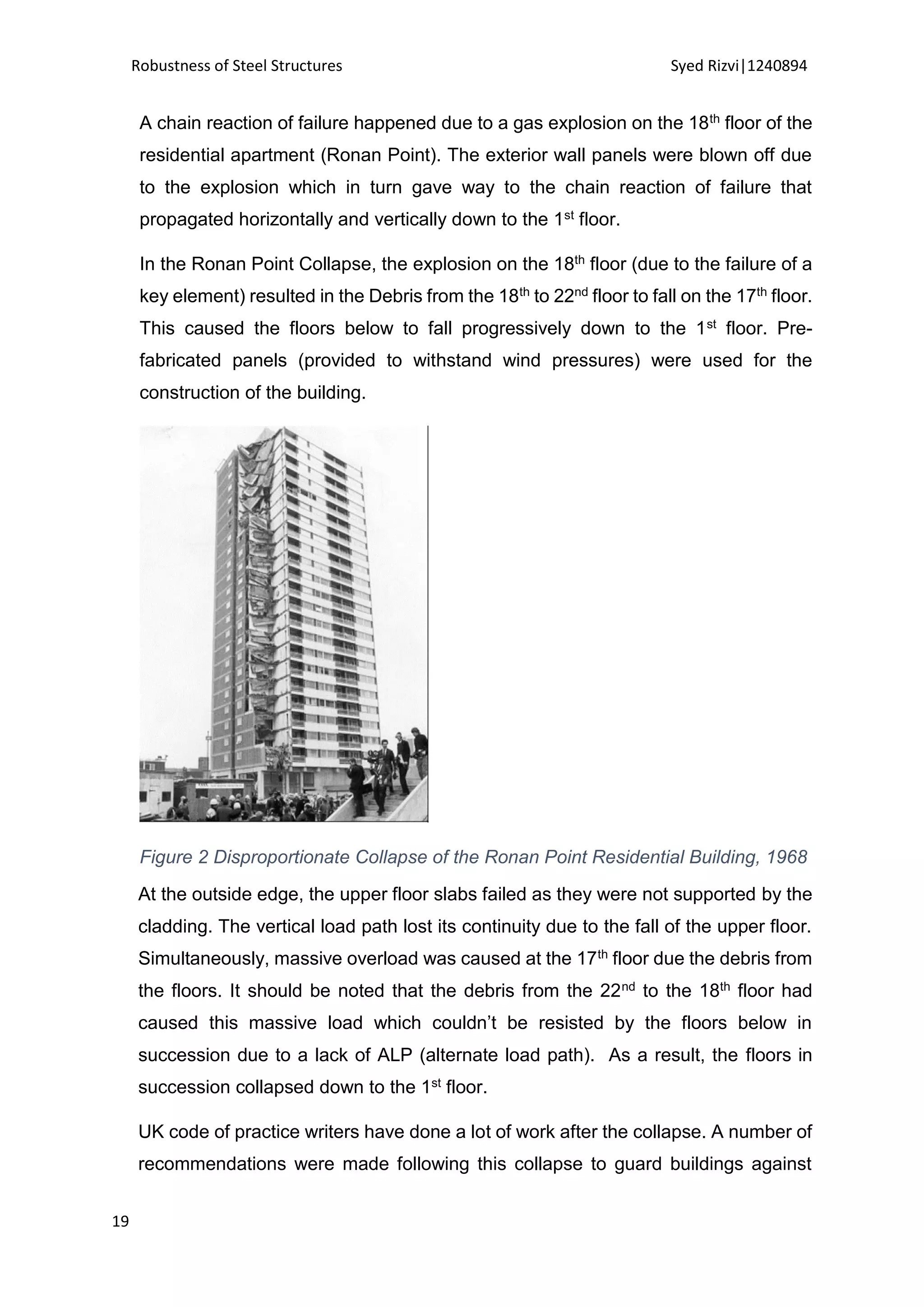
2.5.1 Ronan Point, London UK, 1968
The partial collapse of the Ronan Point was one of the first incidents of progressive
collapse which ignited a series of researches, specifically in the UK. [The Structural
Engineer, 1969; ISE, 1969]](https://image.slidesharecdn.com/cbc42944-264e-4f32-8a90-056033ebe7a4-150617175605-lva1-app6891/75/Dissertation-19-2048.jpg)
![Robustness of Steel Structures Syed Rizvi|1240894
20
progressive collapse. In the UK, the recommendations were adopted covering
continuity, loading and ductility. A vertical element may be removed without
causing unacceptable damage in structures with a certain number of stories where
it is not possible for the ties to meet the requirements [DETR, 1994; ODPM, 2004].
If in any case, the vertical members can’t be removed then it should be able to
withstand a specified force in any direction [HMSO, 1991; HMSO, 1992; DETR,
1994; ODPM, 2004].
Clearly, to account for accidental loading and ‘tying’ structural members together
were reconsidered by the following Building Regulations [HMSO, 1970; HMSO,
1976].
2.5.2 Alfred P. Murrah Federal Building, USA, 1995
A large vehicle bomb was detonated approximately 5m from the north face of the
nine storey Murrah Building in Oklahoma City.
Around 168 fatalities were caused due to this incident [Corley et al, 1998; Corley,
2004]. A considerable damage was sustained to the Murrah Building.
The bomb exploded about 5 meters far on the north side of the building (see figure
3). In this explosion, the RC slab and column construction was damaged. The
columns G16, G24 failed in shear after the G20 column was destroyed. From east
wall to the column G12 the girder (transfer girder) lacked support. The frame was
left with 3 columns missing (G16, G20, G24) and could not support itself. The
calculations to support this claim were made by [Corley et al, 1998]. The two bays
on the south side, 8 bays on the northern part of the building.
Three possible mechanisms were discussed by Corley in 2004. The main cause of
the collapse was concluded to be a lack of continuity in the reinforcement in
structures:
1. Transfer girder or
2. Base of the column.](https://image.slidesharecdn.com/cbc42944-264e-4f32-8a90-056033ebe7a4-150617175605-lva1-app6891/75/Dissertation-21-2048.jpg)
![Robustness of Steel Structures Syed Rizvi|1240894
21
Figure 3: Collapse of the Murrah Federal Building 1995 [Corley 1998]
Some of the changes that were recommended/introduced for design in federal
buildings after the Oklahoma city bombing in US were compartmentalised
construction, special moment frames and Dual systems. Such systems [Corley et
al, 1998] would help increase the stability and toughness of the structures if brought
under a sudden loading. This would also allow the building to reduce the probability
of a collapse and help it act in a better manner by the provision of strength and
extra mass.
2.5.3 World Trade Centre, New York USA, 2001
The 110 storey high World Trade Centre towers on September 11, 2001 saw two
hijacked airplanes collide in to it. In the history of the United States, this turned out
to be the worst disaster in which around 3000 people lost their life [FEMA 2001].
Immediately after the attacks, the Structural Engineering Institute of the ASCE and
Federal Emergency Management Agency (FEMA) formed a team of engineering
specialists. It was concluded that the impact had caused localised damaged. The
building finally saw a total collapsed when the steel frame was weakened by the
heat of the fire.](https://image.slidesharecdn.com/cbc42944-264e-4f32-8a90-056033ebe7a4-150617175605-lva1-app6891/75/Dissertation-22-2048.jpg)
![Robustness of Steel Structures Syed Rizvi|1240894
22
Figure 4: Progressive Collapse of the World Trade Centre 2001
The collapse was described by Corley [Corley, 2004] as:
“Once the collapse began, potential energy stored in the upper part of the structure
during construction was rapidly converted into kinetic energy. Collapsing floors
above accelerated and impacted on the floors below, causing an immediate,
progressive series of floor failures, each punching in turn onto the floor below. The
collapse of the floors left tall, freestanding portions of the exterior wall. As the
unsupported height of these freestanding exterior wall elements increased, they
buckled at the bolted column splice connections and also collapsed. The process
was essentially the same for both Tower1 and Tower2”.](https://image.slidesharecdn.com/cbc42944-264e-4f32-8a90-056033ebe7a4-150617175605-lva1-app6891/75/Dissertation-23-2048.jpg)
![Robustness of Steel Structures Syed Rizvi|1240894
25
More research was needed in this area to be put into existing research. For the
prevention of progressive collapse in the future, a need for the development of a
National Standard for progressive collapse was outlined [MMC, 2003]
2.5.4 Discussion
Progressive collapse is a topic that has been widely debated over the last few
decades. Researches started as early as 1968. Some of the early works may be
listed as follows: [HMSO, 1968; The Structure Engineer, 1969; ISE, 1969; Allen
and Schriever, 1972; Popoff, 1975].
[HMSO, 1968; HMSO, 1970; BSI, 1972; HMSO, 1976; BSI, 1985; BSI, 1990;
HMSO, 1991; HMSO, 1992] are some of the drafted rules on disproportionate
collapse by the UK in response to the Ronan Point Collapse.
[BSI, 2000; Way, 2003; SCI 98/99] are three stages that of design procedures that
were implemented by the UK to avoid disproportionate collapse.
A minimum tying force is specified in the direct design procedure for minimum tying
strategy so that the structural members are tied in horizontally by ensuring the
required minimum force. Many countries have adopted this design code as it is an
acceptable solution for design against progressive collapse.
An issue which has been under studied is whether these recommendations provide
adequate protection against the collapse discussed. Since, there has not been
much research conducted in this area it wold recommended to do so.
After the 9/11 attack, the understanding of the progressive collapse was
questioned in that whether it was well understood or not. However, the WTC
collapse (2001) was not the first terrorist attack in the USA. Oklahoma City bombing
of the Alfred P. Murrah building also saw a major structural failure due to
progressive collapse in 1995. Progressive collapse was related to nearly 80% of
168 fatalities caused in this incident rather than the explosion [Corley et al, 1998].
The building heavily relied on a few elements (such as transfer girders) rather than
relying on more than on (more than one) load transfer path.
The future Federal Buildings in the US are built as per the new design
recommendation such as the Compartmentalised construction and special frame](https://image.slidesharecdn.com/cbc42944-264e-4f32-8a90-056033ebe7a4-150617175605-lva1-app6891/75/Dissertation-26-2048.jpg)

![Robustness of Steel Structures Syed Rizvi|1240894
28
3.1 Introduction
To study the behaviour of structures under progressive collapse a specific method
was to be chosen in order to full fill the objectives of the research. Therefore, it was
decided to use the FEM (Finite Element Method). The FEM is a highly
sophisticated and able tool for examining structures’ response under damage (local
failure in this case).
In this section, the advantages and applications of the FEM would be considered.
The FEM analyses a smaller region of a more large and complex system into
simpler parts minimizing errors to provide a solution.
The structural components’ formulation would be briefly re-evaluated. Also, the
implementation of such a formulation in the research would be examined s
required.
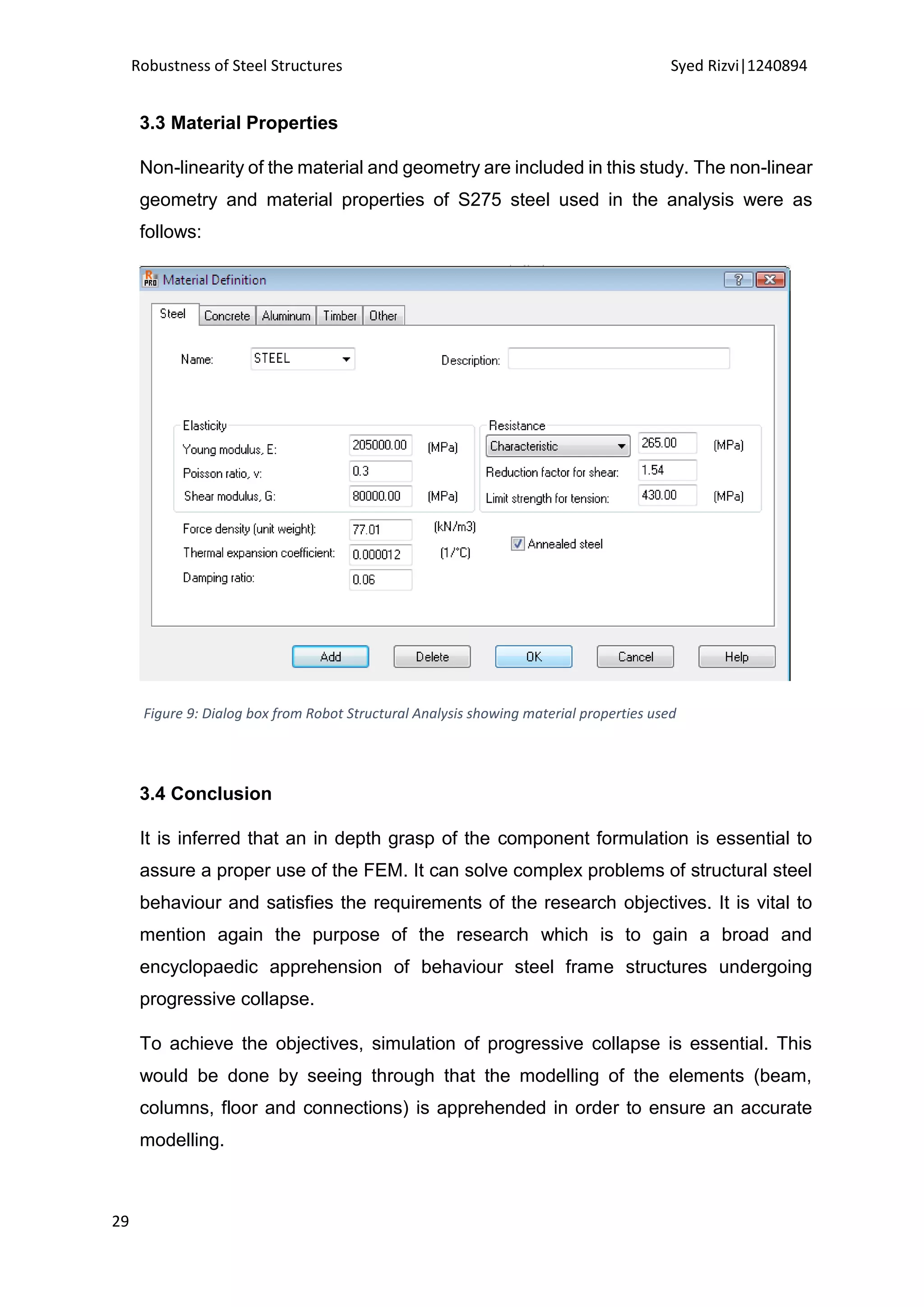
3.2 Application
As discussed earlier, the research focuses on the behaviour of steel frame
structures when subjected to failure in a key element. Examination of a structure
in case of being damaged by an accidental loading makes it very difficult to predict.
Static analysis as compared to the dynamic analysis of a structure is less
complicated in general. When an attempt is made at analysing the structure
dynamically, time-related damping and inertia have to be taken into consideration
[Clough, 1975]. It would therefore be of utmost importance to choose the right FEM
software (analysis code).
The FE code requirements to reach the established objectives should be covered.
The FE code should be able to model complex events and be able to combine
loads such as the self-weight with loads that would result when a key element is
removed.
The parameters such as the P-8 (P-Delta) effect [Gupta, 1999] in non-linear
deflection modelling should also be satisfied as they form the pillars of such a
complex analysis.
The modelling of geometrical behaviour non-linearly should also be a pre-requisite
for such an analysis.](https://image.slidesharecdn.com/cbc42944-264e-4f32-8a90-056033ebe7a4-150617175605-lva1-app6891/75/Dissertation-29-2048.jpg)

![Robustness of Steel Structures Syed Rizvi|1240894
37
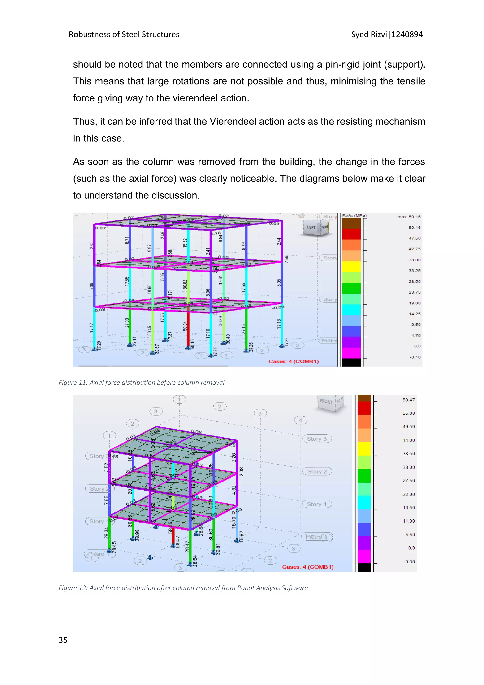
What is more important to notice is the change of axial force in the corner columns
of the floor (floor 1/storey 2) above the floor where the column was removed. This
sudden increase in the column is responsible for the catenary action and the
bending moment to develop. If the new equilibrium is not achieved, these sudden
change in forces can have a higher effect and cause the structure to collapse
progressively. It should also be noted that such collapse can also be encountered
successfully if continuity is ensured at the design stage of the structure. Transfer
girders can also form an important element when alternative load path
methodology is applied.
4.3.3 Discussion
The research aims to examine the tying force generated and the resisting
mechanism of pin joint steel frames. A frame was analysed and the critical forces
generated were studied to gain a better understanding of the behaviour of such
frames.
Attempts at bracing the small 3D frame were made for the provision of lateral
stability. An external support to provide lateral stiffness was also made. This was
not finalised as it was found that such a support would cause extra loading and
effect the results.
For the analysis of the non-linear static analysis of the load path method, the load
factors used are:
2.0 [(0.9 or 1.2) Gk + (0.5Qk or 0.2Sk)] + 0.2Wk
An addition of the dynamic load factor of 2 was accounted because of the static
nature of the analysis.
The strategy of the survival of the structure was discussed. The tension steel would
only take the axial load while relying purely on catenary action mentioned in the
previous section. The analysis carried out also suggests that columns above help
support catenary at the mid-span vie the tie forces. The complexities in the
mechanism of the response in the collapse make it difficult to form accurate
calculations but an approximate/ crude calculation helped suggest collapse or
survival.](https://image.slidesharecdn.com/cbc42944-264e-4f32-8a90-056033ebe7a4-150617175605-lva1-app6891/75/Dissertation-38-2048.jpg)
![Robustness of Steel Structures Syed Rizvi|1240894
40
5.1 Introduction
The Robot Structural Analysis Software uses the Finite Element Method to model
and design the structures. It provides a friendly user interface for the study of
behaviour of real structures in various complex situations.
The structural collapse of a 5 bay by 3 bay 3D structure is modelled and analysed.
The study includes the investigation of dynamic effects. The steel frames of the
structure at hand were
5.2 Structural Modelling
5.2.1 Introduction
A 5 bay (along y axis) by 3 bay (along x axis) was examined.
Design details: The structure was designed as per the requirements of BS5950-1:
2000 [BSI, 2000].
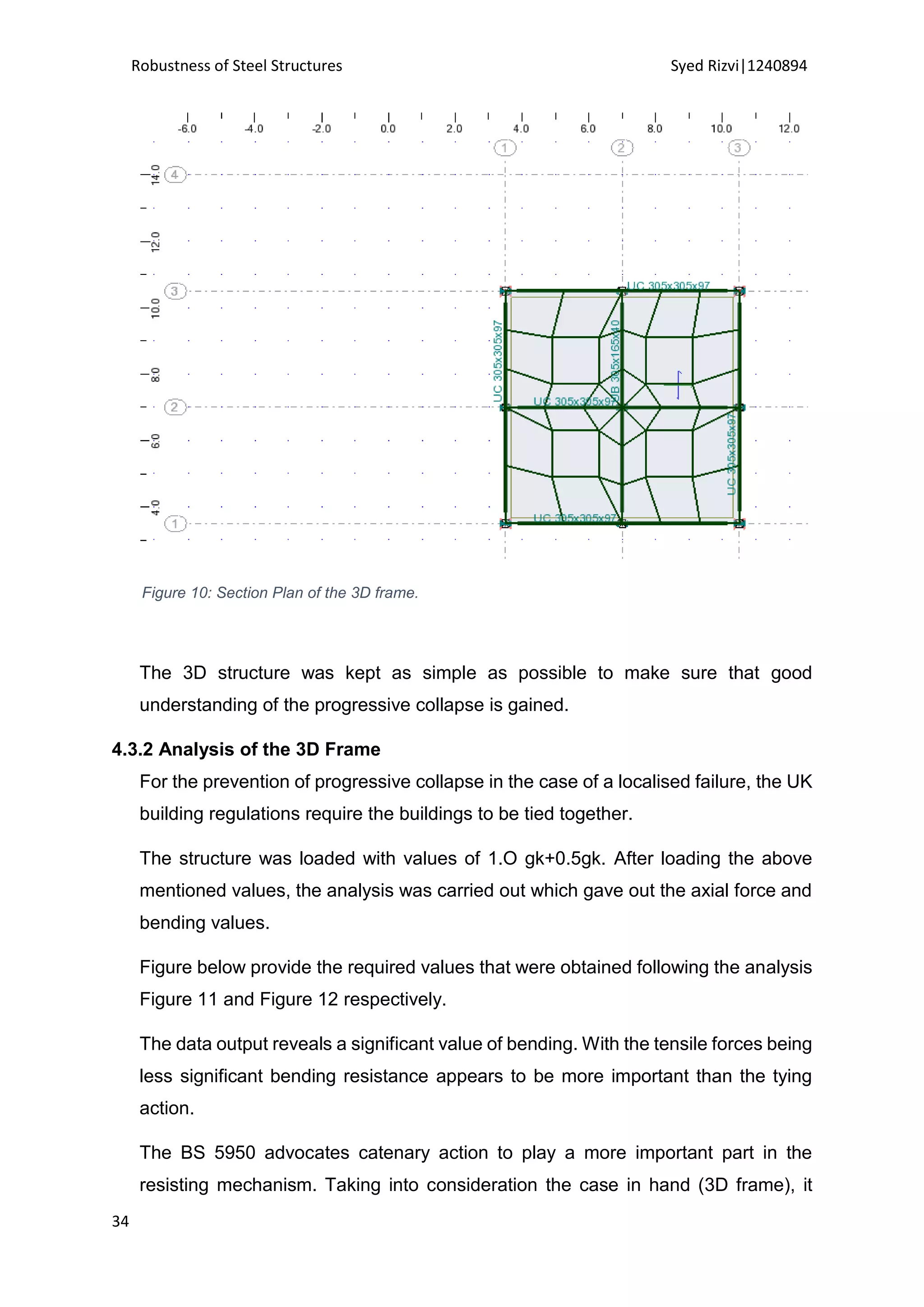
Figure 14: Side frame of the 3 by 5 bay Structure](https://image.slidesharecdn.com/cbc42944-264e-4f32-8a90-056033ebe7a4-150617175605-lva1-app6891/75/Dissertation-41-2048.jpg)
![Robustness of Steel Structures Syed Rizvi|1240894
41
Frame action incorporating moment resistance provides lateral resistance along
the X direction. Along the Y axis, the frame is braced. This provides lateral stiffness
and takes care of the swaying issue as discussed in the previous section.
A statically indeterminate structure is formed by the combination of each structural
component providing lateral stiffness in the continuous frames. As these complex
calculations required for the analysis of this 3D structure are not possible, therefore,
a combination of linear static analysis cases was carried out with the help of a
software [Robot Structural Analysis Software (Autodesk)].
Frames are currently classified as ‘non-sway’ in the steel design code. This is so if
the P-Delta effects are neglected whereas if the effects are not neglected, frames
are classified as sensitive to sway. Elastic critical load helps to determine the
Second Order Effects.
The P-delta effect was not neglected in this case. If the P-delta effect was ignored
this would mean that large member sections would be required. Therefore, in order
to choose the normal size of members for the sake of practicality [Brown, 2002], it
was decided to include the P-Delta effect.
Since the members in this case are designed to resist moments it is acceptable to
approximate for P-Delta effects related to sway (movement). The front facing
frames in figure 17 (pin-frame structure) are the sway frames. As discussed earlier,
it is not possible to use simple tools to analyse a complex behaviour of
‘disproportionate collapse’, the use of Robot Structural Analysis from Autodesk
provides vital guidance to achieve the research objectives. In the previous chapter,
the use of Robot Structural Analysis Software (Finite Element Method) for
modelling and calculations was witnessed to give a realistic behaviour of response
from structures under-going progressive collapse.
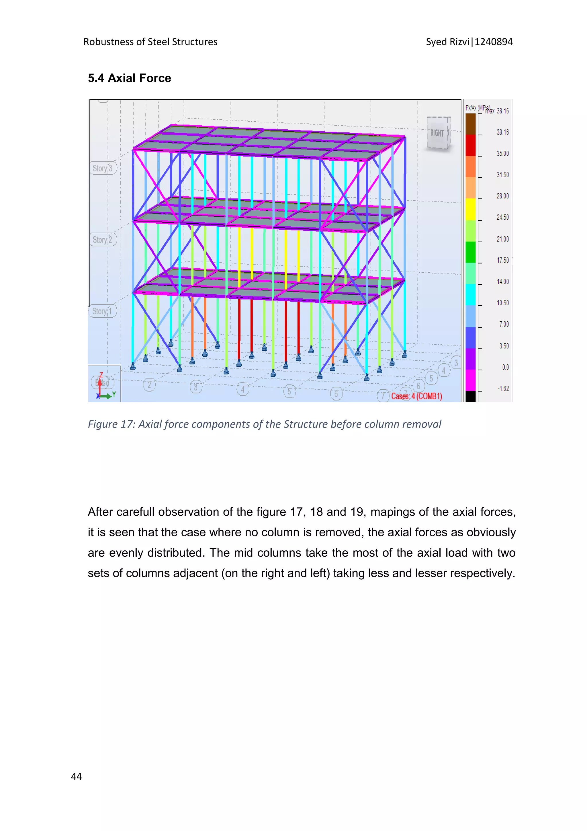
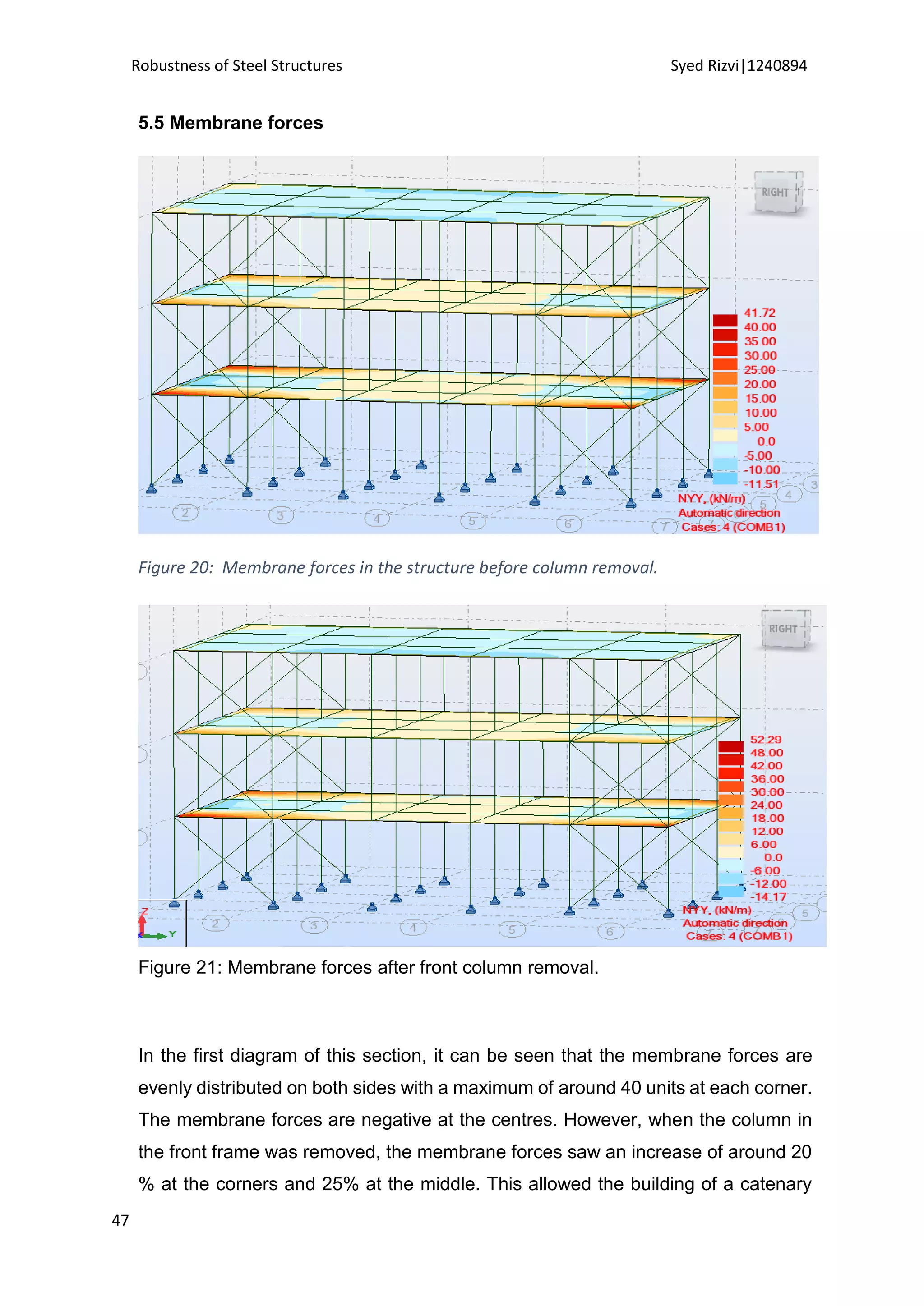
The structure was analysed under three different conditions. Firstly the axial forces,
membrane actions on the bars were recorded under normal design conditions (the
building was designed as per the BS5959). Secondly one of the columns on the
front frame was removed and change in the forces were was observed. Thirdly, a
corner column was removed and the behaviour of the building studied and
analysed.](https://image.slidesharecdn.com/cbc42944-264e-4f32-8a90-056033ebe7a4-150617175605-lva1-app6891/75/Dissertation-42-2048.jpg)
![Robustness of Steel Structures Syed Rizvi|1240894
42
The changes in the forces are discussed in the next chapters.
5.2.2 Issues Faced
The 3D structure is formed of pin-pin frames. One of the issues that was faced due
to this is the detailed modelling of primary beams to avoid buckling.
Pre-cast units in reality can easily solve this issue by providing lateral restraint. The
use of Pseudo beams can however solve this issue effectively with an increase in
the second moment of area. This also helped to retain the right area of cross
section.
The research is concerned about the resisting mechanism of the damaged frame,
therefore, the effect of pseudo beam section on bending resistance would not affect
the research. Also, the load distribution path would not be affected by this.
5.3 Discussion
The 3 bay by 5 bay structure was designed as per the BS 5950 regulations, details
of which are provided in the appendices A.
A statically indeterminate structure is formed by the combination of each structural
component providing lateral stiffness in the continuous frames. As these complex
calculations required for the analysis of this 3D structure are not possible, therefore,
a combination of linear static analysis cases was carried out with the help of a
software [Robot Structural Analysis Software (Autodesk)] which gives the following
results for axial force and membrane forces. A statically indeterminate structure is
formed by the combination of each structural component providing lateral stiffness
in the continuous frames. As these complex calculations required for the analysis
of this 3D structure are not possible, therefore, a combination of linear static
analysis cases was carried out with the help of a software [Robot Structural
Analysis Software (Autodesk)].
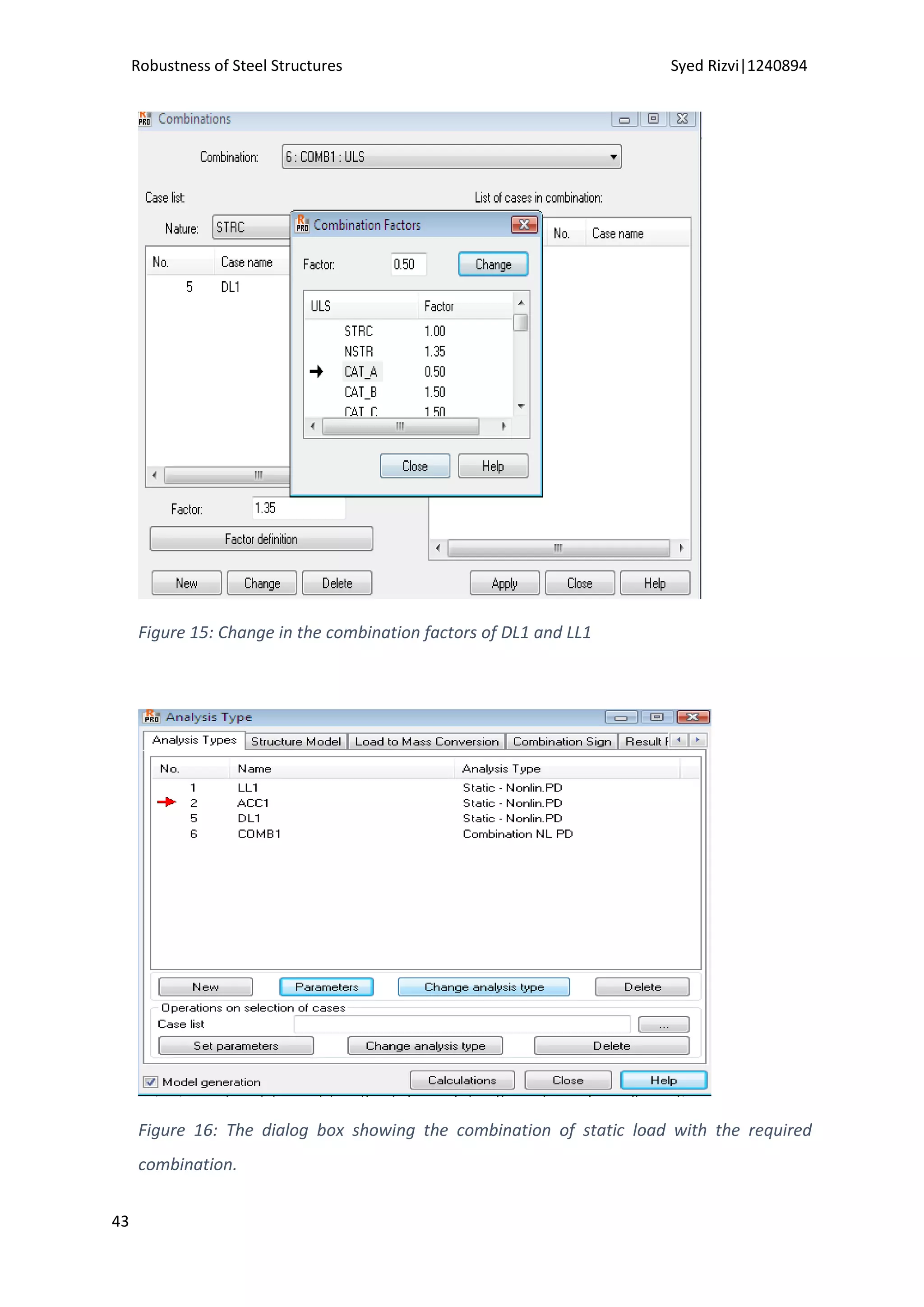
A loading level of 1.0gk and 0.5qk was used. The combination of DL1, LL1 and
ACC was used for the non-linear analysis static analysis.](https://image.slidesharecdn.com/cbc42944-264e-4f32-8a90-056033ebe7a4-150617175605-lva1-app6891/75/Dissertation-43-2048.jpg)

![Robustness of Steel Structures Syed Rizvi|1240894
54
a transfer girder in the Murrah Federal Building could have been used to prevent
progressive collapse.
A study based on the different typologies of the collapse [Uwe Starossek (2009)]
can carried out to give required design values for different typologies. It could also
include the different classes of buildings provided in the modern design codes to
serve as a guidance.](https://image.slidesharecdn.com/cbc42944-264e-4f32-8a90-056033ebe7a4-150617175605-lva1-app6891/75/Dissertation-55-2048.jpg)


![[Liang,_Qing_Quan]_Analysis_and_Design_of_Steel_an(BookZZ.org).pdf](https://cdn.slidesharecdn.com/ss_thumbnails/liangqingquananalysisanddesignofsteelanbookzz-220725050452-4cf9daa6-thumbnail.jpg?width=640&height=640&fit=bounds)


