Download to read offline

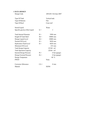
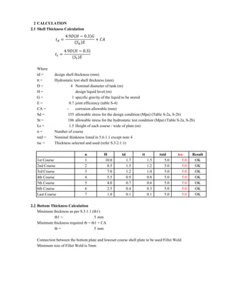
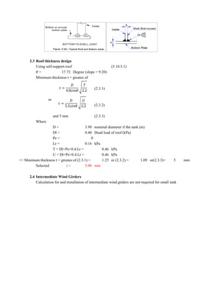

The document outlines the design specifications and calculations for a vertical tank as per API 650 guidelines, detailing parameters such as dimensions, materials, and capacities. It includes calculations for shell, bottom, and roof thicknesses, as well as venting requirements for both vacuum and pressure relief. The tank is designed to hold water with a total capacity of 125.04 m³ and is subject to specific operational criteria including filling and emptying rates.


