
![REFERENCES
[1] Artt, D, Blair, G, RichardsonJ 1982, ‘A Computer Model of a Pulsejet Engine’,
SAE Technical Paper Series, Volume 82 No. 953.
[2] Artt, D, Blair, G, RichardsonJ 1984, ‘Observations on the Design and
Operation of Pulsejet Engines as Derivedfrom an Experimental and Theoretical
Investigation’, SAE Technical Paper Series, Volume 84 No. 422.
[3] Benson, R, Garg, R, Woollatt, D 1964 ‘A Numerical Solution of Unsteady Flow
Problems’, Journal of Mechanical Sciences, Pergamum Press Ltd., Vol. 6.
[4] Fan, Y, Li, J, Wang, J, Zhang, J, Zhang, Y, Experimental investigation on
kerosene/air pneumatic valve pulse detonation engine, Journal of Aerospace
Power. International Journal of Engineering Research& Technology (IJERT)
IJERTIJERT ISSN: 2278-0181 IJERTV3IS090544 Kentfield, J ‘The Potential of
Valveless Pulsejets for Small UAV Propulsion Applications’ AIAA
Journal 1998, No. 3879 .
[6] Ogorelec, B 2005, Valveless Pulsejet Engines 1.5 – a historical review of
valveless pulsejet designs, Terna Information Services, Zagreb Croatia.
[7] Reynst, F H 1961, Pulsating Combustion, Pergamon Press, London ,UK.
[8] Tharatt, C ‘The Propulsive Duct’ Aircraft Engineering, November 1965, pp 327-
337, December 1965, p 359-371 .
[9] Sunnhordvik, A 2007, Valveless Pulse Jet, Accessed 10May 2007.
[10] Simpson, B 2007, The Valveless Pulse Jet, Accessed15April 2007 .
30/08/2017 IIT KGP 15](https://image.slidesharecdn.com/designofpulsejetengineforuavseminar-2-200617030551/75/Design-of-pulse-jet-engine-for-UAV-2-15-2048.jpg)
![[11] Geng, Tao, Numerical simulation of pulsejet engines., 2007
[12] Zh eng, Fei, Computational investigations of high speed pulsejets., 200 9
[13] Tao Geng ,Comparison between Numerically Simulated and Experimentally
MeasuredFlow field Quantities behind a Pulsejet , Daniel E Paxson, 200 8
[14] http://aardvark.co.nz/pjet/valveless.html
[15] www.pulsejetbook.com
30/08/2017 IIT KGP 16](https://image.slidesharecdn.com/designofpulsejetengineforuavseminar-2-200617030551/75/Design-of-pulse-jet-engine-for-UAV-2-16-2048.jpg)

The document presents a detailed design and analysis of a pulse jet engine, including design parameters, combustion analysis, and meshing processes using software like ANSYS Fluent. It outlines various case studies to evaluate performance under different conditions, highlighting the ability to maintain stable pressure and potential for efficiency improvements with optimal exhaust pipe diameter. The conclusion emphasizes the feasibility of building pulse jet engines and their challenges at low flight velocities.
Introduction of Roshan Sah, M.Tech student, presenting on pulse jet engine design.
Details on the pulse jet engine design with valid formulas and key parameters like area, volume, and efficiency.
Overview of CATIA software usage and meshing techniques using ICEM CFD for the engine design.
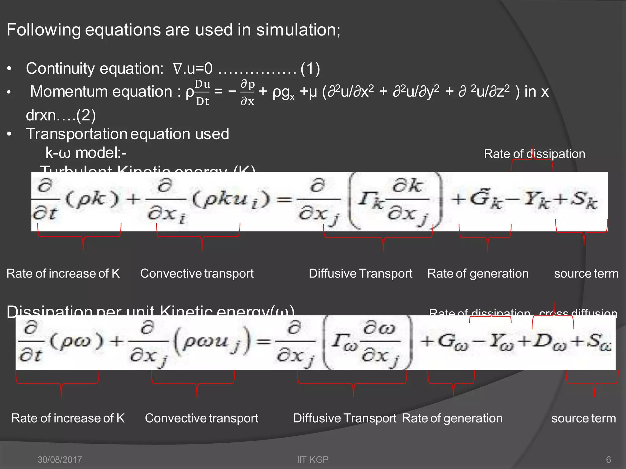
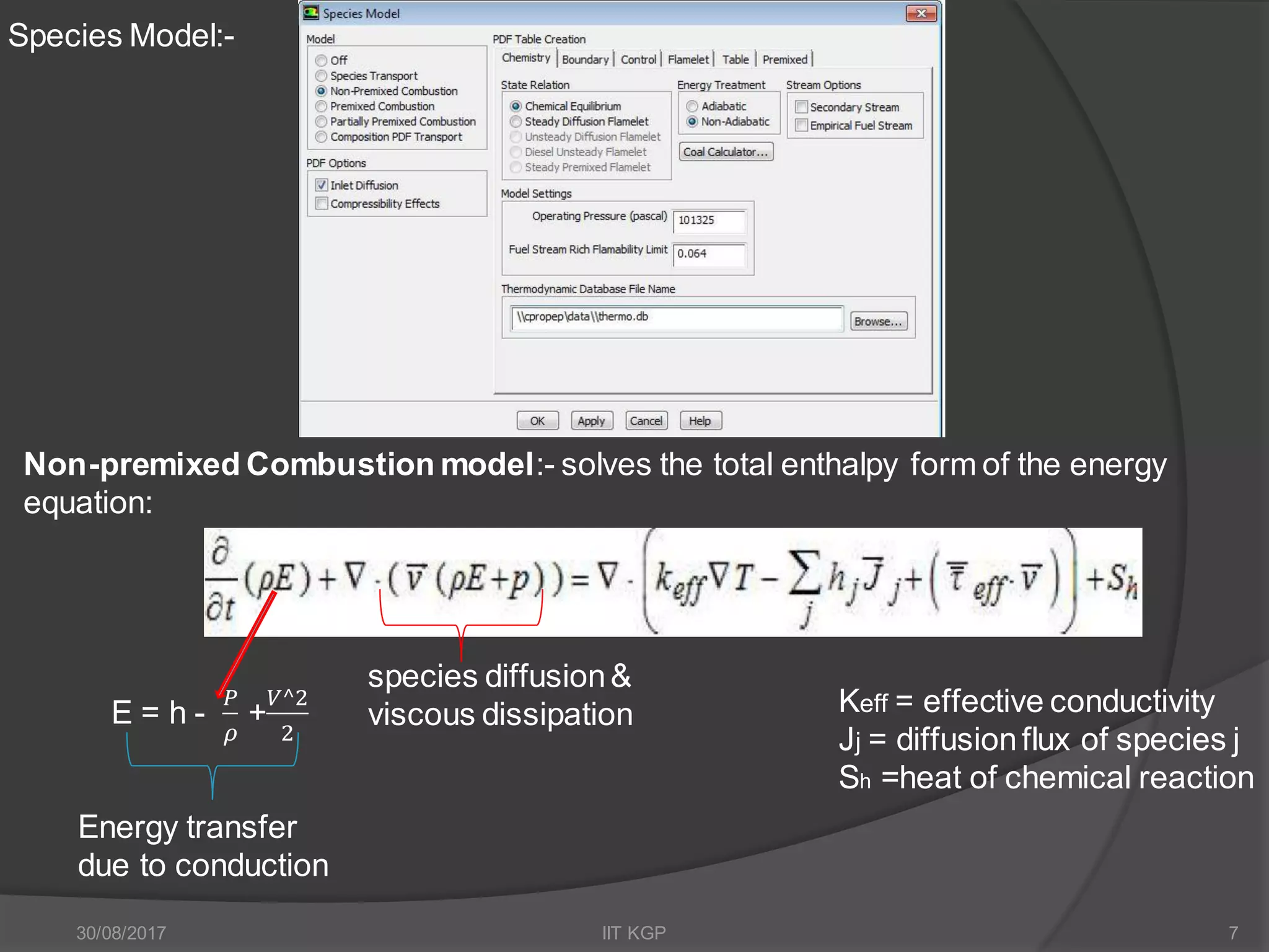
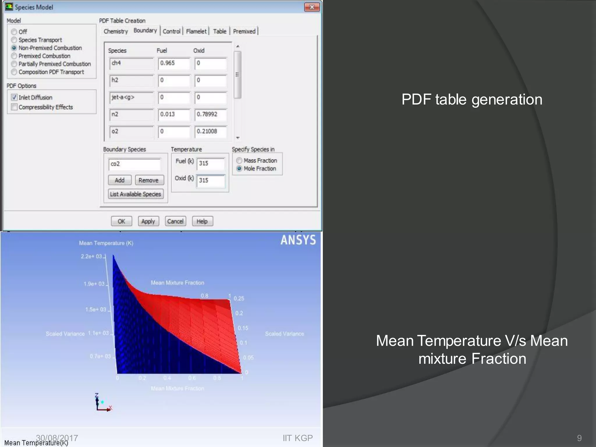
Analysis conducted using ANSYS Fluent for combustion analysis, discussing boundary conditions and equations.
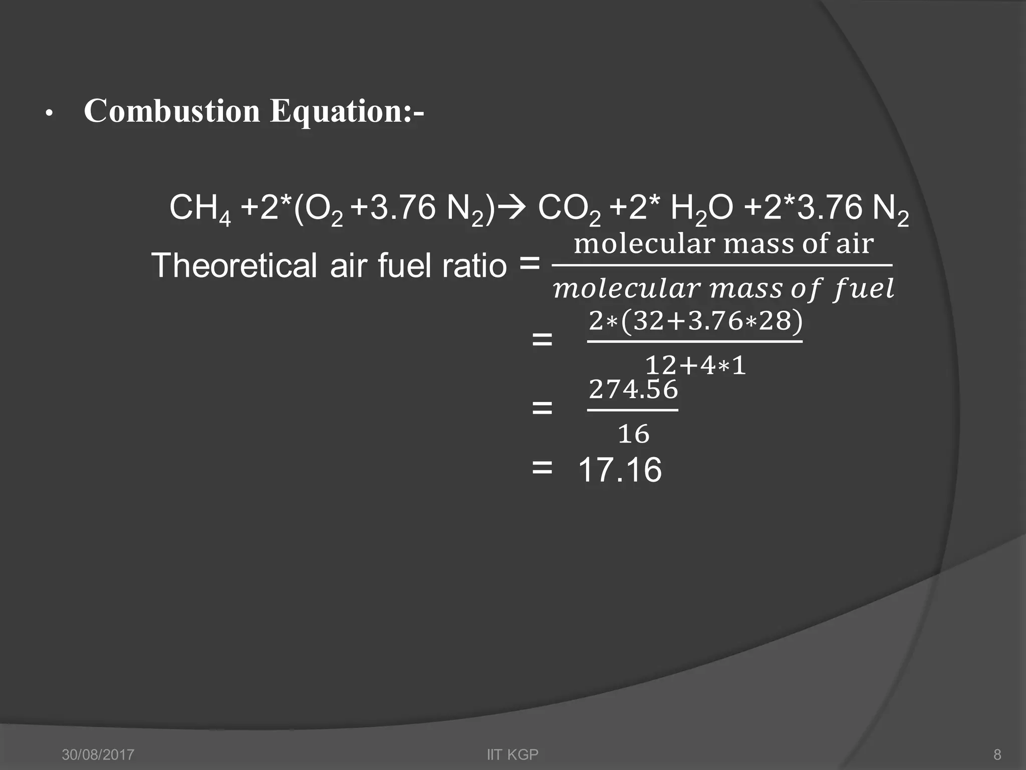
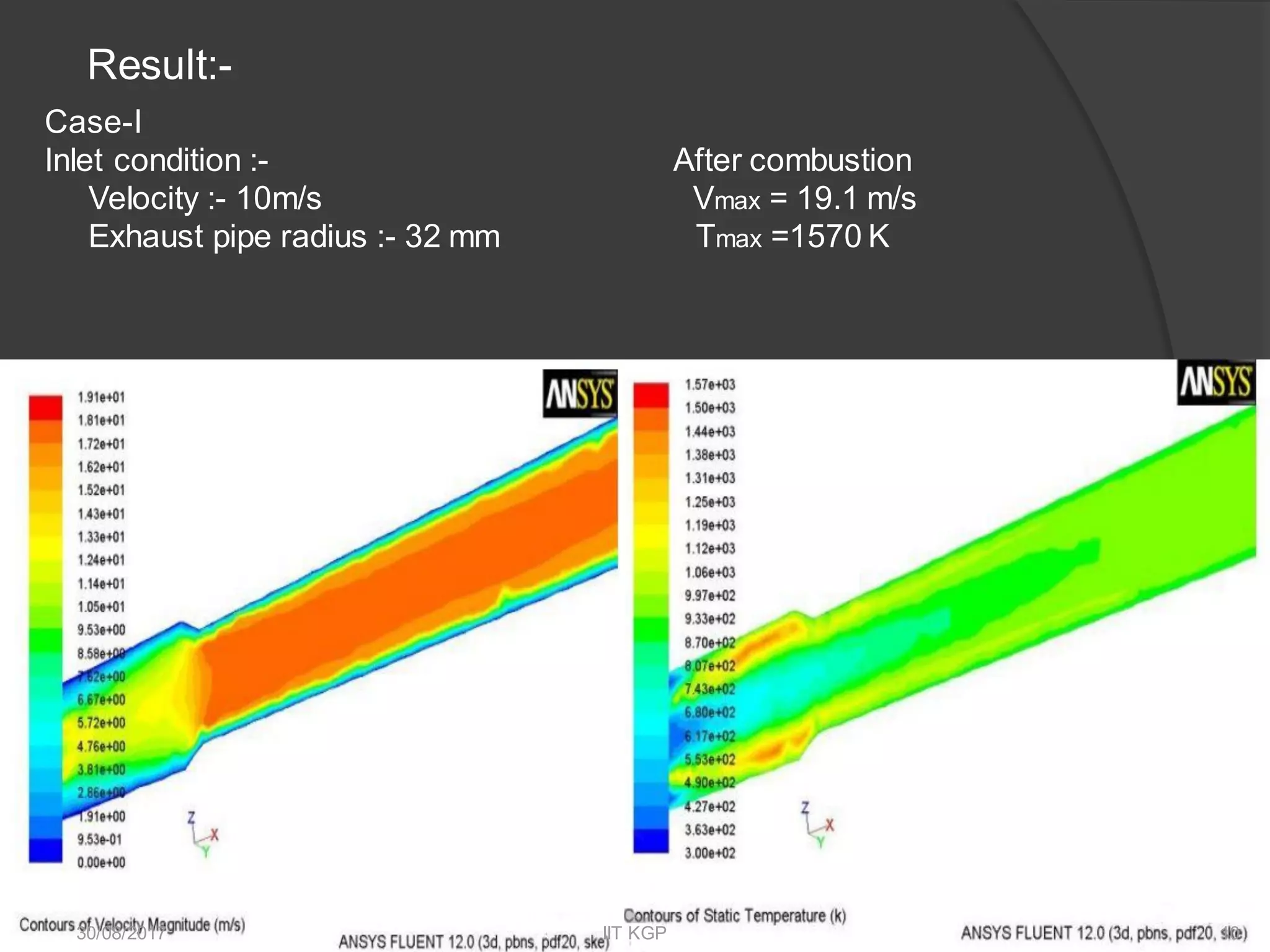
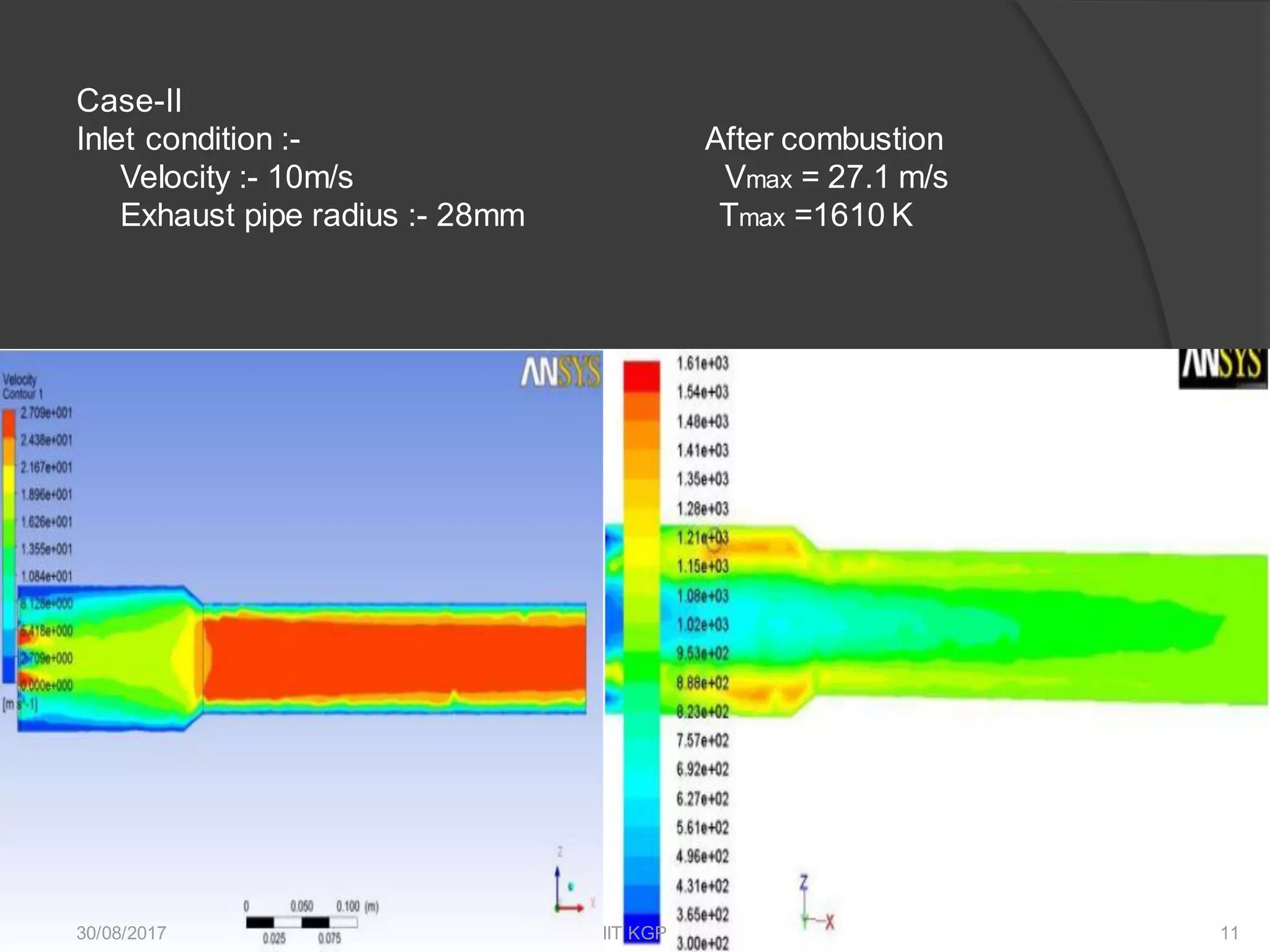
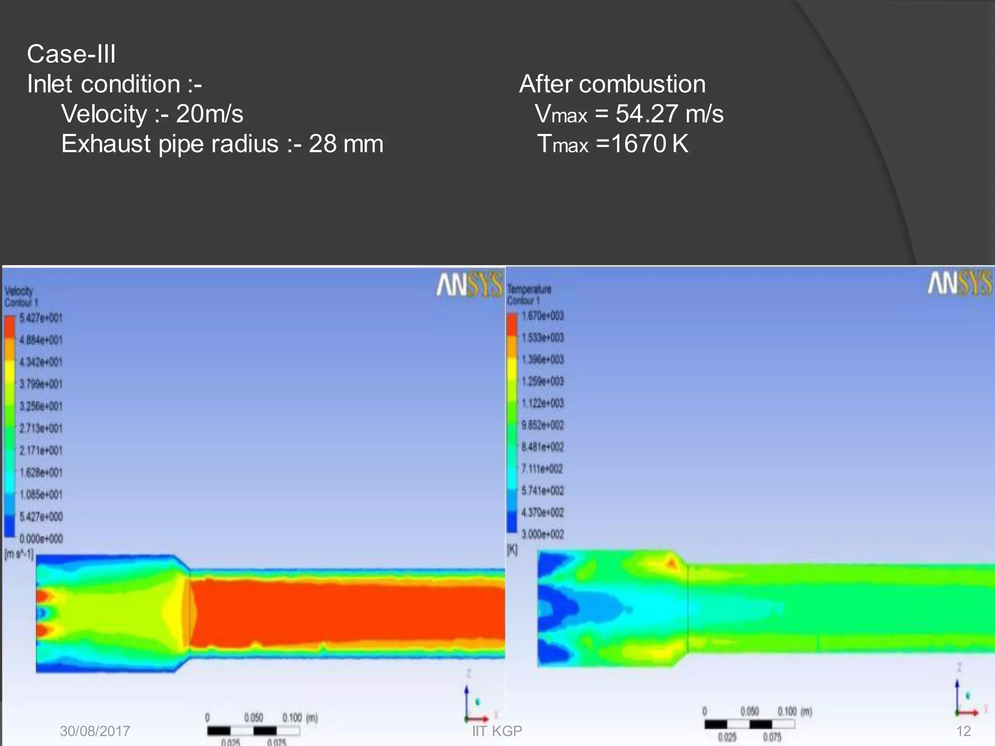
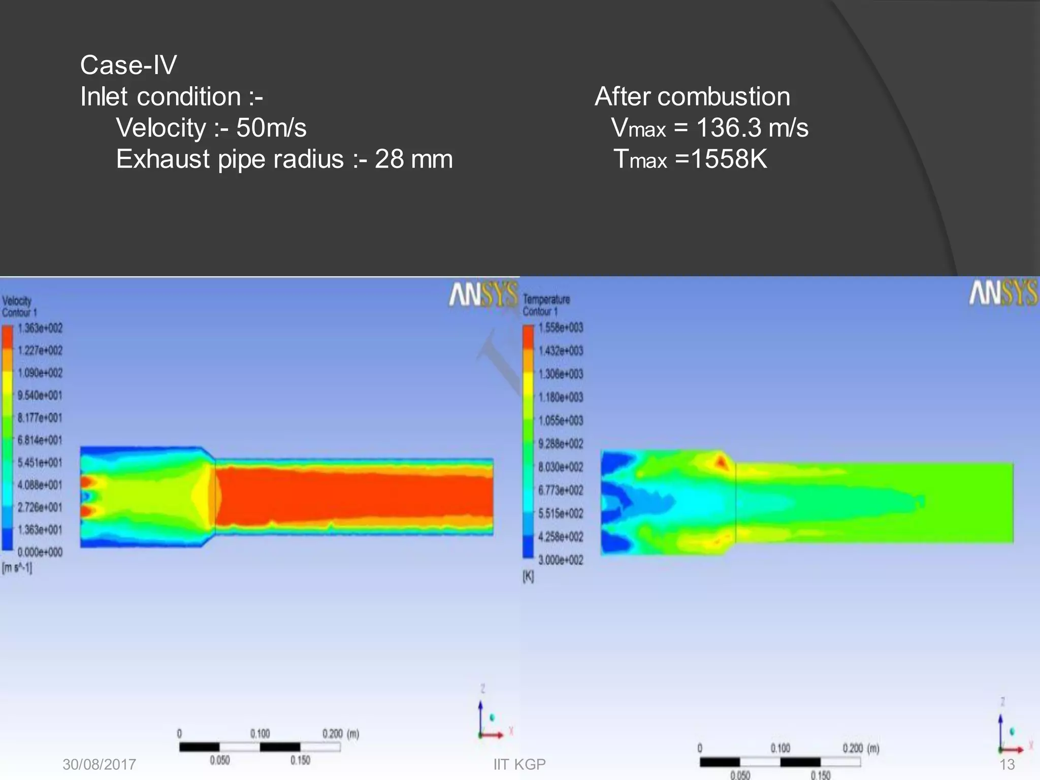
Combustion equation and results from four cases analyzing exhaust conditions, velocities, and temperatures.
List of references used in research including technical papers and historical data on pulse jet engines.


