Downloaded 21 times
![International Journal of Mechanical Engineering and Technology (IJMET), ISSN 0976 – 6340(Print),
ISSN 0976 – 6359(Online), Volume 5, Issue 12, December (2014), pp. 110-117 © IAEME
111
Stirling cycle cryocooler in miniature cryocoolers. New applications of cryocoolers are appearing,
and the requirements for old applications are often undergoing changes. These new and changing
cryocooler requirements have been the impetus for the recent developments in cryocoolers. The lack
of a suitable cryocooler to meet the requirements of a particular application has hampered the
advancement of many applications. The main problems associated with cryocoolers are: reliability,
efficiency, size, weight, vibration and cost. The seriousness of each of these problems depends on the
application. Within the last 15 years satellite applications for cooled infrared sensors have become
much more important. Obviously these applications require a cryocooler with very high reliability,
high efficiency, small size, low weight, and low vibrations. A significant amount of cryocooler
development in the last 15 years has been focused on space applications. Most of the new
developments on Stirling cryocoolers have been focused towards the techniques to improve
reliability. The rapid growth of research and development on Pulse Tube cryocoolers in the last
decade has been because of its potential for improved reliability, simplicity and low cost.
2. COAXIAL GEOMETRICAL ARRANGEMENT OF PTC
Based on geometrical arrangement, Richardson [1] classified Pulse Tube cryocoolers as:
linear,U- tube, Annular and Coaxial Pulse Tube cryocooler. Out of these, each one has it’s own
advantages and disadvantages. The coaxial design overcomes the problem of viscous effect by
accommodating the regenerator in the annular space and using the central cylinder as the pulse tube.
In Walchand College of Engineering, lot of research work is currently going on in Cryogenics field.
But this is the first time that a Coaxial Pulse Tube cryocooler is developed. The present research
work aims to develop a stirling type, split, coaxial pulse tube and a linear compressor (moving coil
type), with 100W of input power. At first the coaxial setup was developed, and later the suitable
compressor, therefore the pulse tube setup was first tested in Cryogenics lab IIT Powai. A
indigenously build compressor[2,3] of 300W capacity was used for testing at IIT,Powai,Mumbai.
3. DESIGN & ANALYSIS OF COAXIAL PTC.
The modeling techniques range in degree of difficulty from the back-of-the-envelop
calculation, to sophisticated nodal network analyses. First order analyses are good for preliminary
design purposes. The classical analysis of the operation of Stirling machines is due to Schmidt. The
second order approach is basically applying the ideal Schmidt analysis [4] (First Order Analysis)
with coupled loss terms. Atrey et al. [5, 6] presented more realistic approach for the analysis of
Stirling cycle liquefier. Zhu and Chen [7] developed isothermal model for analysis of Pulse Tube
cryocooler. The above models are used to design the coaxial PTC, but some losses which arise due to
1800
turn of the gas are not taken into account.
4. FABRICATION AND ASSEMBLY OF COAXIAL PTC.
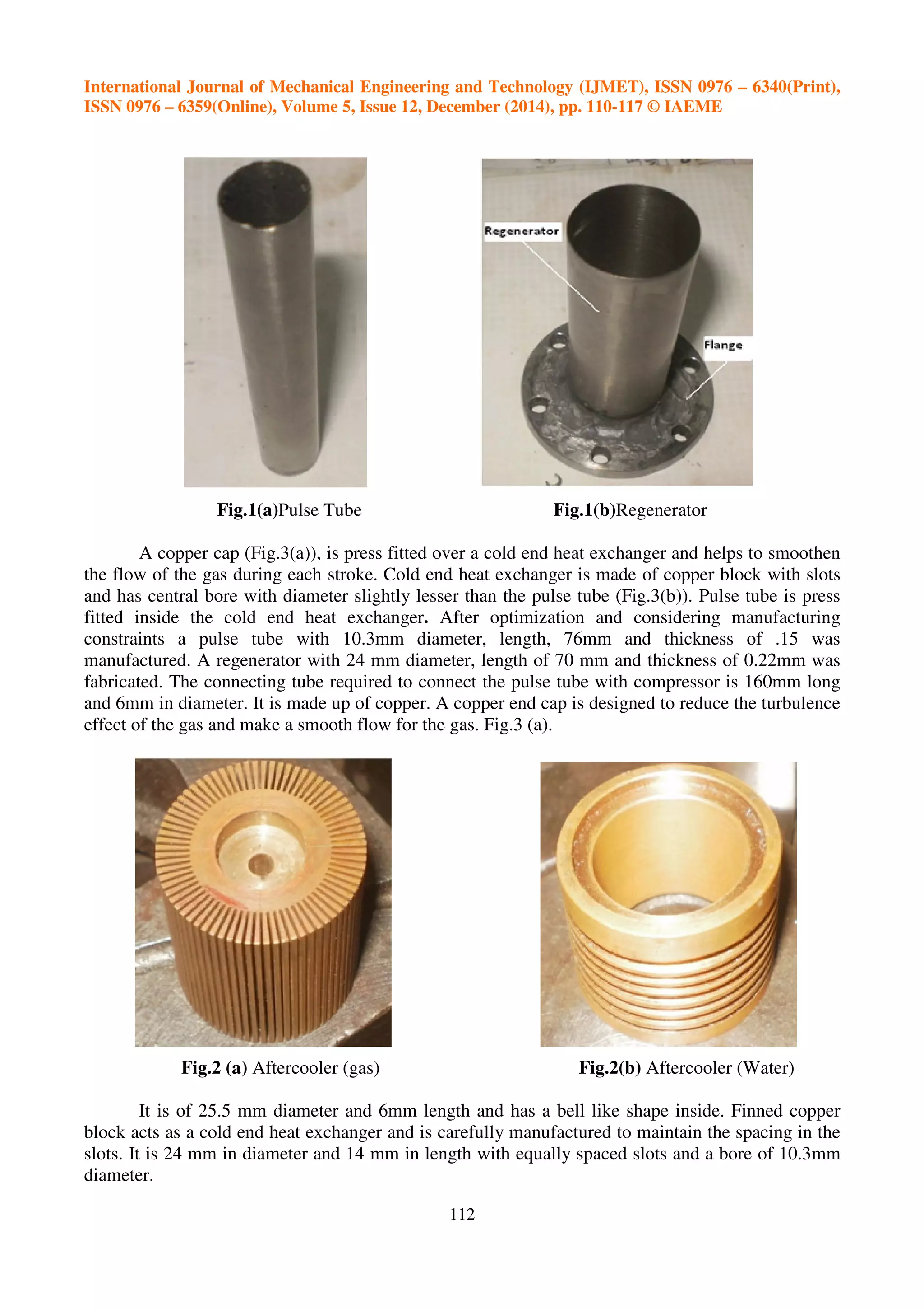
Fabrication and assembly was done in Walchand college of Engineering and nearby
industries. This setup consists of components which need very close tolerance. Manufacturing of
Pulse tube of very thin thickness was a challenge, but it was accomplished. Regenerator and Pulse
tube are made up of stainless steel. As shown in fig. 1. (a& b).](https://image.slidesharecdn.com/design-and-testing-of-stirling-type-coaxial-pulse-tube-cryocooler-160218130603/75/DESIGN-AND-TESTING-OF-STIRLING-TYPE-COAXIAL-PULSE-TUBE-CRYOCOOLER-2-2048.jpg)
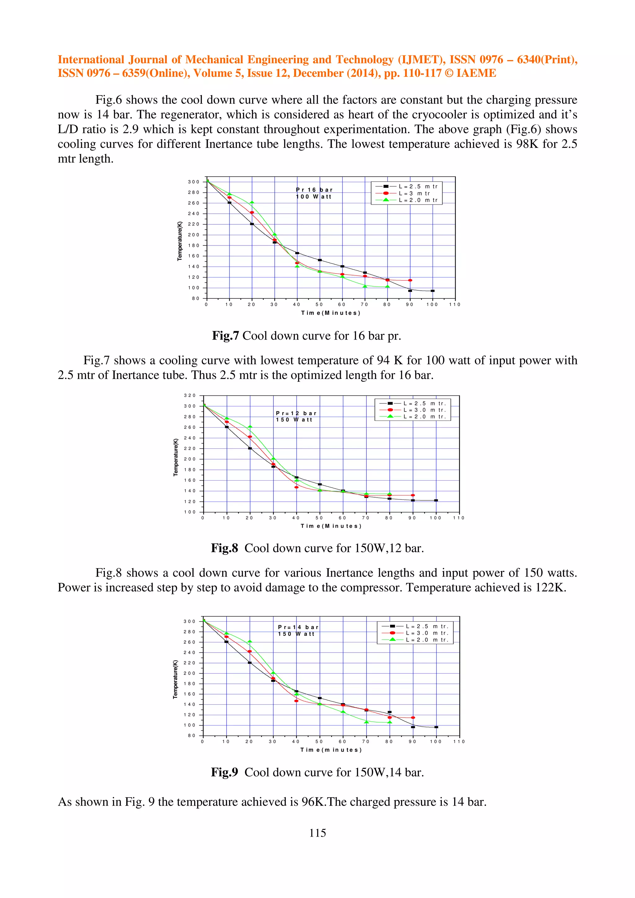


The document discusses the design, fabrication, and testing of a Stirling-type coaxial pulse tube cryocooler developed at Walchand College of Engineering. The system aimed to achieve low temperatures (targeting around 80K), with experimental results showing a lowest temperature achieved of 94K at various power inputs. The research highlights the importance of optimizing design parameters like inertance tube length and charging pressure in enhancing the performance of pulse tube cryocoolers.


![Seller Deck - Presentation [Concert L2].PPTX](https://cdn.slidesharecdn.com/ss_thumbnails/sellerdeck-presentationconcertl2-251219171156-24982daf-thumbnail.jpg?width=640&height=640&fit=bounds)


