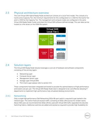
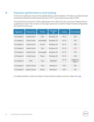
SlideShare a Scribd company logo
1 of 67
Download to read offline
A Dell Reference Architecture
Dell VMware Virtual SAN Ready Nodes
A Reference Architecture document for the design, configuration and
implementation of a Virtual SAN Ready Node Environment with Horizon, VCE
VxRail and VMware Horizon Air Hybrid-Mode.
Dell Engineering
August 2016
2 Dell VMware Virtual SAN Ready Nodes
Revisions
Date Description
June 2016 Initial release
July 2016 Updated with HY-8 R730, Thin Clients, added VCE VxRail, NSX, GPU, RDSH and
Horizon Air Hybrid-Mode
August 2016 All-Flash configuration added
THIS WHITE PAPER IS FOR INFORMATIONAL PURPOSES ONLY, AND MAY CONTAIN TYPOGRAPHICAL ERRORS AND TECHNICAL INACCURACIES.
THE CONTENT IS PROVIDED AS IS, WITHOUT EXPRESS OR IMPLIED WARRANTIES OF ANY KIND.
Copyright © 2016 Dell Inc. All rights reserved. Dell and the Dell logo are trademarks of Dell Inc. in the United States and/or other jurisdictions. All
other marks and names mentioned herein may be trademarks of their respective companies.
3 Dell VMware Virtual SAN Ready Nodes
Table of contents
Revisions............................................................................................................................................................................................. 2
1 Introduction................................................................................................................................................................................6
1.1 Purpose.............................................................................................................................................................................6
1.2 Scope ................................................................................................................................................................................6
1.3 What’s new.......................................................................................................................................................................6
2 Solution Architecture Overview .............................................................................................................................................. 7
2.1 Introduction ..................................................................................................................................................................... 7
2.2 What is a Virtual SAN Ready Node (VSRN)?................................................................................................................ 7
2.3 Physical architecture overview.....................................................................................................................................8
2.4 Solution layers .................................................................................................................................................................8
2.4.1 Networking.......................................................................................................................................................................8
2.4.2 Virtual SAN Ready Node (VSRN) Host .........................................................................................................................9
2.4.3 Storage (VMware Virtual SAN).......................................................................................................................................9
2.5 Virtual SAN Ready Node ...............................................................................................................................................11
2.5.1 Virtual SAN Ready Node (Hybrid Configuration)......................................................................................................11
2.5.2 Virtual SAN Ready Node (All-Flash Configuration) ................................................................................................. 12
2.5.3 Virtual SAN Ready Node– Network Architecture.................................................................................................... 12
3 Hardware components........................................................................................................................................................... 14
3.1 Network .......................................................................................................................................................................... 14
3.1.1 Dell Networking S3048 (1Gb ToR switch) ................................................................................................................ 14
3.1.2 Dell Networking S4048 (10Gb ToR switch).............................................................................................................. 15
3.2 Virtual SAN Ready Nodes (VSRN) ............................................................................................................................... 15
3.2.1 VSRN R730 HY-8........................................................................................................................................................... 16
3.2.2 VSRN R730 HY-6........................................................................................................................................................... 17
3.2.3 VSRN R630 HY-4 .......................................................................................................................................................... 18
3.2.4 VSRN R730XD HY-8 ..................................................................................................................................................... 19
3.2.5 VSRN R730 AF-8............................................................................................................................................................20
3.2.6 VSRN R730 AF-4............................................................................................................................................................ 21
3.2.7 VSRN R630 AF-4 ...........................................................................................................................................................22
3.2.8 VSRN 730XD AF-8.........................................................................................................................................................23
3.2.9 Summary Comparison .................................................................................................................................................24
4 Dell VMware Virtual SAN Ready Nodes
3.3 VCE VxRail ......................................................................................................................................................................24
3.3.1 What is VCE VxRail Appliance? ...................................................................................................................................24
3.3.2 VCE VxRail Technical Overview..................................................................................................................................26
3.4 VCE VxRail and Dell Wyse Datacenter ......................................................................................................................28
3.5 GPUs................................................................................................................................................................................30
NVIDIA GRID K1 and K2 ...............................................................................................................................................30
NVIDIA Tesla M60 ......................................................................................................................................................... 31
3.6 Dell Wyse Thin Clients..................................................................................................................................................32
Wyse 5030 PCoIP Zero Client ....................................................................................................................................32
Wyse 5050 AIO PCoIP Zero Client ............................................................................................................................33
Wyse 7030 PCoIP Zero Client ....................................................................................................................................33
Wyse 5010 Thin Client (ThinOS) with PCoIP............................................................................................................33
Wyse 5040 AIO Thin Client with PCoIP....................................................................................................................34
Wyse 3030 LT Thin Client (ThinOS)...........................................................................................................................34
Wyse 5010 Thin Client (Windows Embedded 8 Standard) ....................................................................................35
Wyse 7010 Thin Client (Windows Embedded Standard 8) ....................................................................................35
Dell Venue 11 Pro..........................................................................................................................................................35
Dell Chromebook 13................................................................................................................................................36
3.6.11Wyse 5020 Thin Client.................................................................................................................................................36
Wyse 7040 Thin Client.................................................................................................................................................36
4 Software Components............................................................................................................................................................37
4.1 VMware ...........................................................................................................................................................................37
4.1.1 VMware vSphere 6........................................................................................................................................................37
4.1.2 What’s new in this release of Virtual SAN .................................................................................................................37
4.1.3 VMware Horizon View.................................................................................................................................................. 41
4.1.4 Horizon Air Hybrid-Mode............................................................................................................................................44
4.2 Microsoft RDSH.............................................................................................................................................................45
vGPU Profiles .................................................................................................................................................................47
4.3 NVIDIA GRID vGPU....................................................................................................................................................... 51
5 Solution architecture for vSRN with Horizon .....................................................................................................................52
5.1 Management server infrastructure.............................................................................................................................52
5.1.1 SQL databases ...............................................................................................................................................................52
5 Dell VMware Virtual SAN Ready Nodes
5.1.2 DNS..................................................................................................................................................................................52
5.2 Storage Architecture Overview ..................................................................................................................................53
5.2.1 Virtual SAN Local Storage............................................................................................................................................53
5.3 Virtual Networking ........................................................................................................................................................54
5.3.1 VSRN Network Configuration.....................................................................................................................................54
5.3.2 VMware NSX...................................................................................................................................................................57
5.4 Scaling Guidance ..........................................................................................................................................................59
5.5 Solution High Availability ............................................................................................................................................ 60
5.5.1 Virtual SAN HA/ FTT configuration ............................................................................................................................ 61
5.5.2 vSphere HA.....................................................................................................................................................................62
5.5.3 Horizon View infrastructure protection....................................................................................................................62
5.5.4 Management server high availability .........................................................................................................................62
5.5.5 Horizon View VCS high availability ............................................................................................................................62
5.5.6 SQL Server high availability .........................................................................................................................................63
5.6 VMware Horizon View communication flow...........................................................................................................64
6 Solution performance and testing........................................................................................................................................65
Acknowledgements........................................................................................................................................................................66
About the Authors...........................................................................................................................................................................67
6 Dell VMware Virtual SAN Ready Nodes
1 Introduction
1.1 Purpose
This document addresses the architecture design, configuration and implementation considerations for
the key components of the architecture required to deliver virtual desktops via VMware Horizon View on
Virtual San Ready Nodes (vSRN) with vSphere 6.0 Update 2 on Virtual SAN 6.2.
1.2 Scope
Relative to delivering the virtual desktop environment, the objectives of this document are to:
 Define the detailed technical design for the solution.
 Define the hardware requirements to support the design.
 Define the constraints, which are relevant to the design.
 Define relevant risks, issues, assumptions and concessions – referencing existing ones where
possible.
 Provide a breakdown of the design into key elements such that the reader receives an incremental
or modular explanation of the design.
 Provide scaling component selection guidance.
1.3 What’s new
 Introduce Virtual SAN Ready Nodes
 Introduce Hybrid configuration for Virtual SAN
 Introduce Virtual SAN new features
 Introduce All-Flash configuration for Virtual SAN
7 Dell VMware Virtual SAN Ready Nodes
2 Solution Architecture Overview
2.1 Introduction
Dell Wyse Datacenter solutions provide a number of deployment options to meet your desktop
virtualization requirements. Our solution is able to provide a compelling desktop experience to a range of
employees within your organization from task workers to knowledge workers to power users. The
deployment options for Dell Wyse Datacenter include:
 Linked Clones(Non-persistent)
 Full Clone Virtual Desktops (Persistent)
 RDSH with Virtual SAN
2.2 What is a Virtual SAN Ready Node (VSRN)?
A Virtual SAN Ready Node is a validated Dell Server configuration in a tested, verified Hardware form factor
for Virtual SAN deployments, jointly recommended by Dell and VMware. This makes the process easier for
the customer and from the vSRN compatibility page Link they can select any of the Dell Hybrid
configuration depending on their requirements. There is also an option of having the ready nodes factory
installed so ESXi and Virtual SAN would be installed/configured in the factory/merge center. This also
comes with pre-selected Horizon OEM VMware SKU’s for licensing and support of Horizon on Virtual SAN.
8 Dell VMware Virtual SAN Ready Nodes
2.3 Physical architecture overview
The core Virtual SAN Hybrid Ready Node architecture consists of a Local Tier1 model. This consists of a
Cache and a Capacity Tier, the minimum requirements for this configuration is 1 x SSD for the Cache Tier
and 1 x HDD for the Capacity Tier. The management and compute nodes are configured in the same
Virtual SAN Ready Node Cluster and share the Virtual SAN software defined storage. The user data can be
hosted on a file server on the VSAN file system.
2.4 Solution layers
The Virtual SAN Ready Node Solution leverages a core set of hardware and software components
consisting of five primary layers:
 Networking Layer
 Compute Server Layer
 Management Server Layer
 Storage Layer (Virtual SAN)
 Thin Client Layer (please refer to section 3.5)
These components have been integrated and tested to provide the optimal balance of high performance
and lowest cost per user. The Virtual SAN Ready Node stack is designed to be cost effective allowing IT
departments to implement high-performance fully virtualized desktop environments.
2.4.1 Networking
Only a single high performance Dell Networking 10Gb 48-port switch is required to get started in the
network layer. This switch hosts all solution traffic consisting of 10Gb LAN sources for smaller stacks.
Above 500 users we recommend that 10Gb LAN be used with Virtual SAN traffic separated into discrete
Switching Fabrics. Additional switches are added and stacked as required to provide High Availability for
9 Dell VMware Virtual SAN Ready Nodes
the Network layer. When there is a requirement for 1Gb connectivity for DRAC/remote management so
we can use an existing 1Gb ToR or add a Dell Networking 1Gb 48-port switch for this function.
2.4.2 Virtual SAN Ready Node (VSRN) Host
The compute, management and storage layers are converged into a single server Virtual SAN Ready Node
(VSRN) Series appliance cluster, hosting VMware vSphere. The recommended boundaries of an individual
cluster are based on number of the nodes supported for vSphere 6 which is 64.
Dell recommends that the VDI management infrastructure nodes be separated from the compute
resources , in this configuration both management and compute are in the same Virtual SAN Cluster but
the management node is reserved for management VMs only and this will be expanded to depending on
the size of the cluster. Compute hosts can be used interchangeably for Horizon or RDSH as required.
2.4.3 Storage (VMware Virtual SAN)
10 Dell VMware Virtual SAN Ready Nodes
VMware Virtual SAN is software-defined storage solution fully integrated into vSphere. Once enabled on a
cluster, all the magnetic hard disks present in the hosts are pooled together to create a shared data store
that will be accessible by all hosts in the Virtual SAN cluster. Virtual machines can then be created and a
storage policy can be assigned to them. The storage policy will dictate availability / performance and
sizing.
From a hardware perspective, at least three ESXi hosts (four recommended) are required for the Virtual
SAN cluster. Each host will need at least one SSD and one HDD. The SSD acts as a read cache and a write
buffer. The read cache keeps a list of commonly accessed disk blocks and the write cache behaves as a
non-volatile write buffer. It is essential to the performance of the Virtual SAN as all I/O goes to the SSD
first. The higher the performance of the disks then the better the performance of your virtual machines. It’s
important to determine the number of simultaneous write operations that a particular SSD is capable of
sustaining in order to achieve adequate performance.
All virtual machines deployed to Virtual SAN have an availability policy setting that ensures at least one
additional copy of the virtual machine data is available; this includes the write cache contents. When a
write is initiated by the VM then it is sent to both the local write cache on the owning host and also to the
write cache on the remote hosts. This ensures we have a copy of the in cache data in the event of a host
failure and no data will get corrupted. If a block is requested and not found in the read cache, the request
is directed to the HDD.
Magnetic hard disk drives (referred to as HDDs from here on) have two roles in Virtual SAN. They make up
the capacity of the Virtual SAN data store as well as making up components for a stripe width. SAS, NL-SAS
and SATA drives are supported.
VMware recommends configuring 10% of projected consumed capacity of all VMDKs space as SSD
storage on the hosts. If a higher ratio is required, then multiple disk groups (up to 4) will have to be created
as there is a limit of 1 SSD per disk group.
11 Dell VMware Virtual SAN Ready Nodes
Virtual SAN implements a distributed RAID concept across all hosts in the cluster, so if a host or a
component within a host (e.g. an HDD or SSD) fails then virtual machines still have a full complement of
data objects available and can continue to run. This availability is defined on a per-VM basis through the
use of VM storage policies.
Virtual SAN 6.2 provides two different configuration options, a hybrid configuration that leverages flash-
based devices for the cache tier and magnetic disks for the capacity tier, and an all-flash configuration.
This delivers enterprise performance and a resilient storage platform. The all-flash configuration uses flash
for both the cache tier and capacity tier.
There are two ways to build a Virtual SAN cluster, build your custom configuration using the HCL Link or
choose the Dell VMware Certified Ready Nodes Link.
2.5 Virtual SAN Ready Node
2.5.1 Virtual SAN Ready Node (Hybrid Configuration)
The Local Tier 1 Virtual SAN Ready Nodes Hybrid configuration model provides a scalable rack-based
configuration that hosts user VDI sessions on local SSD (cache) and spinning disk (capacity) in the
compute layer.
The R730 HY-8 configuration is using the x16 backplane and consists of two disk group, each diskgroup
consists of 1 x SSD + 7 x HDDs
The R730 HY-6 configuration is using the x8 backplane and consists of one disk group (1 x SSD + 7 x
HDD).
12 Dell VMware Virtual SAN Ready Nodes
2.5.2 Virtual SAN Ready Node (All-Flash Configuration)
The Local Tier 1 Virtual SAN Ready Nodes All-Flash configuration model provides a scalable rack-based
configuration that hosts user VDI sessions on local SSD drives for cache and for capacity.
The R730 AF-8 configuration is using the x16 backplane and consists of two disk groups, each disk group
consists of 1 x SSD (write intensive) + 6 x SSDs (mixed use).
The R730 AF-4 configuration is using the x8 backplane and consists of one disk group 1 x SSD (write
intensive) + 7 x SSDs (mixed use).
2.5.3 Virtual SAN Ready Node– Network Architecture
In the Local Tier 1 architecture, a single Dell Networking switch is shared among all network connections
for both management and compute, up to 500 users. Over 500 users Dell Wyse Solutions Engineering
recommends separating the network Fabrics to isolate Virtual SAN and LAN traffic as well as making each
13 Dell VMware Virtual SAN Ready Nodes
switch stack redundant. Only the compute servers connect to Virtual SAN storage in this model. All Top of
Rack (ToR) traffic is layer 2 (L2)/ switched locally, with all layer 3 (L3)/ routable VLANs trunked from a core
or distribution switch. The following diagrams illustrate the logical data flow in relation to the core switch.
14 Dell VMware Virtual SAN Ready Nodes
3 Hardware components
3.1 Network
The following sections contain the core network components for the Dell Wyse Datacenter solutions.
General uplink cabling guidance to consider in all cases is that TwinAx is very cost effective for short 10Gb
runs and for longer runs use fiber with SFPs.
3.1.1 Dell Networking S3048 (1Gb ToR switch)
Accelerate applications in high-performance environments with a low-latency top-of-rack (ToR) switch
that features 48 x 1GbE and 4 x 10GbE ports, a dense 1U design and up to 260Gbps performance. The
S3048-ON also supports Open Network Installation Environment (ONIE) for zero-touch installation of
alternate network operating systems.
Model Features Options Uses
Dell Networking
S3048-ON
48 x 1000BaseT
4 x 10Gb SFP+
Non-blocking, line-rate
performance
260Gbps full-duplex
bandwidth
131 Mpps forwarding rate
Redundant hot-swap
PSUs & fans
1Gb
connectivity
VRF-lite, Routed VLT,
VLT Proxy Gateway
User port stacking (up
to 6 switches)
Open Networking
Install Environment
(ONIE)
15 Dell VMware Virtual SAN Ready Nodes
3.1.2 Dell Networking S4048 (10Gb ToR switch)
Optimize your network for virtualization with a high-density, ultra-low-latency ToR switch that features 48
x 10GbE SFP+ and 6 x 40GbE ports (or 72 x 10GbE ports in breakout mode) and up to 720Gbps
performance. The S4048-ON also supports ONIE for zero-touch installation of alternate network
operating systems.
Model Features Options Uses
Dell Networking
S4048-ON
48 x 10Gb SFP+
6 x 40Gb QSFP+
Non-blocking, line-rate
performance
1.44Tbps bandwidth
720 Gbps forwarding rate
VXLAN gateway support
Redundant hot-swap
PSUs & fans
10Gb
connectivity
72 x 10Gb SFP+ ports
with breakout cables
User port stacking (up
to 6 switches)
Open Networking
Install Environment
(ONIE)
For more information on the S3048, S4048 switches and Dell Networking, please visit: LINK
3.2 Virtual SAN Ready Nodes (VSRN)
In the Local Tier 1 model, VDI sessions execute from local storage on each Compute server. The
hypervisor used in this solution is vSphere. In this model, both the Compute and Management server hosts
access Virtual SAN storage. The management VLANs are configured across 2 x 10Gb on the additional
10Gb NIC but can also be configured across the 2 x 1Gb Network Daughter Cards (NDCs) if 1Gb
16 Dell VMware Virtual SAN Ready Nodes
management is only required but 10Gb is recommended. The Virtual SAN traffic is configured separately
on the 2 x 10Gb NDCs. Refer to section 2.4 for cabling implications.
3.2.1 VSRN R730 HY-8
The foundation of the Dell Wyse Datacenter solution portfolio is the best-in-class Dell PowerEdge R730.
This dual socket CPU platform runs the fastest Intel Xeon E5-2600 v4 family of processors, can host up to
24 DIMMs of DDR4 RAM, supports up to 16 x 2.5” SAS disks and can be outfitted with 2 double-wide GPU
accelerators from AMD or NVIDIA. The Dell PowerEdge R730 offers uncompromising performance and
scalability in a 2U form factor.
VSRN Host
PowerEdge R730
2 x Intel Xeon E5-2698v4 Processor (2.2Ghz)
512GB Memory (16 x 32GB RDIMMs, 2400MT/s)
VMware vSphere on internal 16GB Dual SD
2 x 400GB SSD
14 x 1.2TB SAS
PERC H730 Integrated RAID Controller
Embedded 2 x Intel X520 DP 10Gb DA/SFP+
Embedded 2 x Intel I350 DP 1Gb Ethernet
Intel X520 DP 2 x 10Gb DA/SFP+ Server Adapter, LP
iDRAC8 Enterprise
2 x 750W PSUs
17 Dell VMware Virtual SAN Ready Nodes
3.2.2 VSRN R730 HY-6
VSRN Host
PowerEdge R730
2 x Intel Xeon E5-2660v4 Processor (2.0Ghz)
384GB Memory (24 x 16GB RDIMMs, 2400MT/s)
VMware vSphere on internal 16GB Dual SD
1 x 800GB SSD
7 x 1.2TB SAS
PERC H730 Integrated RAID Controller
Embedded 2 x Intel X520 DP 10Gb DA/SFP+
Embedded 2 x Intel I350 DP 1Gb Ethernet
Intel X520 DP 2 x 10Gb DA/SFP+ Server Adapter, LP
iDRAC8 Enterprise
2 x 750W PSUs
18 Dell VMware Virtual SAN Ready Nodes
3.2.3 VSRN R630 HY-4
The Dell R630 is a 1U platform with a broad range of configuration options. Each appliance comes
equipped with dual CPUs, 10 to 20 cores, and up to 384GB of high-performance RAM by default. A
minimum of two disks are required in each host, 1 x SSD for the Cache tier (Tier1) and 1 x HDD for the
Capacity tier (Tier2) .This configuration has one diskgroup which consists of 1 x SSD and 7 x SAS disks. The
16GB mirrored pair of SD modules boots the ESXi hypervisor while the PERC H730p is configured in pass-
through mode connecting to the SSDs and HDDs. Each platform can be outfitted with SFP+ or BaseT
NICs.
VSRN Host
PowerEdge R630
2 x Intel Xeon E5-2660v4 Processor (2.0Ghz)
384GB Memory (24 x 16GB RDIMMs, 2400MT/s)
VMware vSphere on internal 16GB Dual SD
1 x 400GB SSD
7 x 1TB SAS
PERC H730 Integrated RAID Controller
Embedded 2 x Intel X520 DP 10Gb DA/SFP+
Embedded 2 x Intel I350 DP 1Gb Ethernet
Intel X520 DP 2 x 10Gb DA/SFP+ Server Adapter, LP
iDRAC8 Enterprise
2 x 750W PSUs
19 Dell VMware Virtual SAN Ready Nodes
3.2.4 VSRN R730XD HY-8
The Dell 730XD is a 2U platform that can be configured with 24 x 2.5” disks or 12 x 3.5” disks to serve a
broad range of capacity requirements. Each appliance comes equipped with dual CPUs, 10 to 20 cores,
and up to 512GB of high-performance RAM by default. A minimum of six disks is required in each host, 3 x
SSD for the Cache tier (Tier1) and 3 x HDD for the Capacity tier which can be expanded up to 21 capacity
disks. This configuration supports three disk groups. The PERC H730p is configured in pass-through mode
connecting to the SSDs and HDDs. The ESXi is installed on the 2 x Flexi bay drives and with this
configuration we are not restricted to 512 GB which is the maximum support amount of memory
supported for SD boot. Each platform can be outfitted with SFP+ or BaseT NICs.
VSRN Host
PowerEdge R730XD HY-8
2 x Intel Xeon E5-2698v4 Processor (2.2Ghz)
512GB Memory (16 x 32GB RDIMMs, 2400MT/s)
VMware vSphere on 2 x 250GB Flex Bay HDD
3 x 400GB SSD
18 x 1.2TB SAS
PERC H730 Integrated RAID Controller
Embedded 2 x Intel X520 DP 10Gb DA/SFP+
Embedded 2 x Intel I350 DP 1Gb Ethernet
Intel X520 DP 2 x 10Gb DA/SFP+ Server Adapter, LP
iDRAC8 Enterprise
20 Dell VMware Virtual SAN Ready Nodes
2 x 750W PSUs
3.2.5 VSRN R730 AF-8
The R730 All-Flash configuration consists of both SSD for the cache and capacity tier. The cache tier uses
a write intensive SSD and mixed use SSDs for the capacity tier. The PERC HBA330 supports 12Gb/s &
6Gp/s SAS HDD and SSD.
VSRN Host
PowerEdge R730 AF-8
2 x Intel Xeon E5-2698v4 Processor (2.2Ghz)
512GB Memory (16 x 32GB RDIMMs, 2400MT/s)
VMware vSphere on internal 16GB Dual SD
2 x 400GB SSD
12 x 1.6TB SSD
PERC HBA330
Embedded 2 x Intel X520 DP 10Gb DA/SFP+
Embedded 2 x Intel I350 DP 1Gb Ethernet
Intel X520 DP 2 x 10Gb DA/SFP+ Server Adapter, LP
iDRAC8 Enterprise
2 x 750W PSUs
21 Dell VMware Virtual SAN Ready Nodes
3.2.6 VSRN R730 AF-4
VSRN Host
PowerEdge R730 AF-4
2 x Intel Xeon E5-2660v4 Processor (2.0Ghz)
384GB Memory (24 x 16GB RDIMMs, 2400MT/s)
VMware vSphere on internal 16GB Dual SD
1 x 800GB SSD
7 x 1.6TB SSD
PERC HBA330
Embedded 2 x Intel X520 DP 10Gb DA/SFP+
Embedded 2 x Intel I350 DP 1Gb Ethernet
Intel X520 DP 2 x 10Gb DA/SFP+ Server Adapter, LP
iDRAC8 Enterprise
2 x 750W PSUs
22 Dell VMware Virtual SAN Ready Nodes
3.2.7 VSRN R630 AF-4
The R630 All-Flash configuration consists of both SSD for the cache and capacity tier. The cache tier uses
a write intensive SSD and mixed use SSD’s for the capacity tier. The PERC HBA330 supports 12Gb/s &
6Gp/s SAS HDD and SSD.
VSRN Host
PowerEdge R630 AF-4
2 x Intel Xeon E5-2660v4 Processor (2.0Ghz)
384GB Memory (24 x 16GB RDIMMs, 2400MT/s)
VMware vSphere on internal 16GB Dual SD
1 x 800GB SSD
7 x 1.6TB SSD
PERC HBA330
Embedded 2 x Intel X520 DP 10Gb DA/SFP+
Embedded 2 x Intel I350 DP 1Gb Ethernet
Intel X520 DP 2 x 10Gb DA/SFP+ Server Adapter, LP
iDRAC8 Enterprise
2 x 750W PSUs
23 Dell VMware Virtual SAN Ready Nodes
3.2.8 VSRN 730XD AF-8
The R730XD All-Flash configuration consists of both SSD for the cache and capacity tier. The cache tier
uses a write intensive SSD and mixed use SSDs for the capacity tier. The PERC HBA330 supports 12Gb/s &
6Gp/s SAS HDD and SSD. The ESXi is installed on the 2 x 250GB Flexi bay drives and with this configuration
we are not restricted to 512 GB which is the maximum support amount of memory supported for SD boot.
Each platform can be outfitted with SFP+ or BaseT NICs.
VSRN Host
PowerEdge R730XD AF-8
2 x Intel Xeon E5-2698v4 Processor (2.2Ghz)
512GB Memory (16 x 32GB RDIMMs, 2400MT/s)
VMware vSphere on 2 x 250GB Flex Bay HDD
2 x 800GB SSD
12 x 1.6TB SSD
PERC HBA330
Embedded 2 x Intel X520 DP 10Gb DA/SFP+
Embedded 2 x Intel I350 DP 1Gb Ethernet
Intel X520 DP 2 x 10Gb DA/SFP+ Server Adapter, LP
iDRAC8 Enterprise
2 x 750W PSUs
24 Dell VMware Virtual SAN Ready Nodes
3.2.9 Summary Comparison
The summary of all the VDI Platforms in this Reference Architecture are included in the below table. This
table shows the total usable VM space which has been calculated on the RAW storage value. Also of note
is that this is before a Storage Policy has been implemented.
Platform
Raw
(per Host)
Slack Space (30%)
Usable
VM Space Memory CPU Controller
R630 HY-4 7TB 2.1TB 4.9TB 384GB 14 Core H730
R730 HY-6 8.4TB 2.52TB 5.88TB 384GB 14 Core H730
R730 HY-8 16.8TB 5.04TB 11.76TB 512GB 20 Core H730
R730XD HY-8 21.6TB 6.48TB 15.12TB 512GB 20 Core H730
R630 AF-4 12.8TB 3.84TB 8.96TB 384GB 14 Core HBA330
R730 AF-4 11.2TB 3.36TB 7.84TB 384GB 14 Core HBA330
R730 AF-8 19.2TB 5.76TB 13.44TB 512GB 20 Core HBA330
R730XD AF-8 21.6TB 6.48TB 15.12TB 512GB 20 Core HBA330
3.3 VCE VxRail
3.3.1 What is VCE VxRail Appliance?
VCE VxRail appliances are very powerful Hyper Converged Infrastructure Appliances (HCIA) delivered as
four node 2U appliances. The appliances are built on VMware Virtual SAN technology on VMware VSphere
and EMC software. VCE VxRail allows the seamless addition of additional nodes and appliances providing
four nodes in a single appliance and up to 64 nodes in 16 appliances. VCE VxRail contains the following
software from VMware and EMC
EMC Software
 EMC Recoverpoint for VMs – Providing continuous data protection and point in time recovery
 EMC CloudArray - Allowing expansion of appliance storage into cloud based storage
VMware Software
 VMware Virtual SAN Enterprise - Enterprise Storage solution that shares local disks
25 Dell VMware Virtual SAN Ready Nodes
 VMware vCenter Server - Centralized Management of VMware vSphere environment
 VMware vRealize Log Insight - Provides intuitive actionable dashboards from heterogeneous logs
 VMware vSphere Data Protection - Backup and Recovery solution for vSphere
 VMware vSphere Replication – Hypervisor based asynchronous replication for VMs
VxRail allows customers to start small and scale as there requirements increase. Single-node scaling and
low-cost entry-point options give you the freedom to buy just the right amount of storage and compute,
whether just beginning a project or adding capacity to support growth. A single node all flash appliance
can scale from 48 CPU cores and 30.4 TB of raw data to 112 CPU cores and 76TB of raw data. A 64-node
all-flash cluster delivers 1,792 cores and 1,216TB of raw storage.
VSAN introduces minimal CPU overhead in the solution, and has no memory reservation requirements.
Per Node
Components
VCE VxRail Appliance 200 VCE VxRail Appliance 280F
Processor Cores 20 28
Processor
2 Intel® Xeon® Processor E5-
2660 v3 2.6 GHz
2 Intel® Xeon® Processor E5-2683 v3
2.0GHz /35M Cache
Memory
256GB (16 x 16GB) or 512GB (16 x
32GB)
256GB (16 x 16GB) or 512GB (16 x 32GB)
Caching SSD 400 GB or 800 GB 400 GB or 800 GB
Storage-Raw
(Capacity tier)
4.8 – 10 TB 7.6 – 19 TB
Networking 2 x 10 GbE SFP+ or 2 x RJ45 ports 2 x 10GbE SFP+
Power Supply 2 x 1600W redundant PSUs 2 x 1600W redundant PSUs
The VCE VxRail 280F can support up to 604 VDI VMs per appliance, while the VCE VxRail 200 can support
up to 430 VDI VMs per appliance.
Dedupe and compression dramatically increase the amount of available storage, making the VxRail ideal
for persistent storage VDI solutions, available in all-flash configurations.
26 Dell VMware Virtual SAN Ready Nodes
VCE VxRail is shipped in 9 different specifications providing either all flash or hybrid appliances. A
minimum of 200GB SSD is required for the cache device, but can be increased up to 800GB for higher
performance specifications. The different appliance specifications available are shown here
The first appliance must have four nodes but subsequent appliances can have one, two, three or four
nodes. However, the nodes in each appliance must be of the same type, but there can be a mixture of
appliances in any solution. This allows for addition of resources while still protecting the investment in the
existing appliances.
VCE VxRail includes two new software components to manage and monitor the VxRail solution: VxRail
Manager and VxRail Manager Extension. VxRail Manager provides a user interface for configuring
appliances, managing and provisioning VMs and monitoring the health of the system. VxRail Manager
Extension adds new appliances, monitors resource usage and helps troubleshoot software problems.
3.3.2 VCE VxRail Technical Overview
VCE VxRail is a Software Defined Storage solution based on VMware VSphere and the highly efficient
integrated VMware Virtual SAN technology. VxRail adds simplicity by making it easy to acquire and deploy.
The VCE VxRail appliance Techbook can be found here
VxRail appliances contain from 1 to 4 nodes. Each node contains either one or two Intel Xeon CPUs, 6
storage disks in either all flash or a hybrid mix of flash and hard disk drives.
In hybrid appliances, the SSD disks are used for read caching and write buffering. These SSDs are chosen
to have high performance and endurance and can be selected in 200GB, 400GB or 800GB variants. The
capacity disks in hybrid appliances are either 1.2TB or 2TB 2.5” traditional spinning SAS disks providing up
to 10TB of raw storage per node.
In all flash arrays, two different types of SSD disk are used to meet the needs of the cache and capacity
tiers respectively. The caching SSD disks provide higher write endurance than the capacity SSDs since
27 Dell VMware Virtual SAN Ready Nodes
100% of the writes go to cache first. The caching disks are available in 200GB, 400GB, or 800GB variants.
The capacity disks in all flash appliances are available in 3.84TB SSD providing up to 19GB of raw storage
space per node.
The first appliance in a cluster is fully populated, but subsequent appliances can be partially populated.
There is no disruption in adding further appliances to a cluster. Nodes must be balanced, meaning that all
the nodes in an appliance must be identical, and if a new drive is added to a node to expand available
storage, the other nodes in the appliance must be upgraded
Hybrid appliances and all flash appliances cannot be mixed within the same cluster. 1Gb networking is only
supported in the hybrid configuration but 10Gb is recommended.
VxRail Manager and provides a friendly user interface to manage the VxRail configuration and to monitor
health. VxRail Manager will automatically detect new appliances and guide the administrator through very
simple tasks to get the new appliances operational and available for workloads within a few minutes,
without affecting existing appliances. The image below shows the VxRail Manager.
VxRail Manager Extension is used for adding new appliances, monitoring usage and troubleshooting. It
provides access to suggested EMC articles and forums on VxRail appliances. It can also provide
administrator assisted support in replacing failed disks. You can also consume additional services through
the appliance App Store directly from the VxRail Manager Extension which is shown in the below image.
28 Dell VMware Virtual SAN Ready Nodes
3.4 VCE VxRail and Dell Wyse Datacenter
VCE VxRail provides an optimized solution using well-known existing VMware and EMC management
tools, combined with simple deployment and allowing easy scaling and expansion to cloud based storage.
VxRail addresses customer concerns by allowing flexible scaling (i.e. can add partially populated
appliances) to avoid overprovisioned solutions. VxRail provides an ideal entry point for a VDI deployment.
You can start small with less than 100 VMs and scale in small increments. You can also start with many
more VMs and scale linearly up to 9600 VMs in a cluster.
VCE VxRail is designed to provide support for between 200 and 3200 VMs in a single cluster and is
therefore ideally suited to provide the infrastructure for a variety of VDI solutions and to future proof initial
investment by providing simple scaling to allow for future expansion.
VCE VxRail all flash provides a number of features to protect and reduce data usage on the data stores
through deduplication.
VDI as a high-performance workload can be very demanding on physical resources. In order to maximize
performance and density potential, Dell has selected two optimized VxRail configurations to showcase in
this solution. Based on previous LoginVSI testing using similarly configured VMware Virtual SAN
configurations with VMware Horizon, we will provide sizing guidance for VxRail accordingly.
The VCE VxRail 200 (hybrid) and VCE VxRail 280F (all flash) provide high performance configurations to
match previously optimized Dell Wyse reference solutions.
Dell performs validation on solutions using Login VSI from Login Consultants. Leveraging test results from
other extensive testing CCC engineering has completed using Login VSI Task worker, Knowledge worker
and Power worker on similar configurations, an estimate is provided based on these results and the
expected changes based on the actual E5-26XXv3 processors delivered in the VCE VxRail appliances. The
29 Dell VMware Virtual SAN Ready Nodes
estimates are based on the expected number of VMs per core. This has been shown previously to be a
good indicator of processor ability.
This indicates the expected number of Horizon View linked clones that can be supported on these
appliances for each workload. In addition, it also indicates how much memory and storage is required on
the node to support these densities. The storage requirement is based on a FTT (Failures to Tolerate) of
one. Actual densities will vary based on the configuration of the client images and application been
utilized. The below table shows the previous workload results on E5-2670v3 CPU.
Login VSI Workload
Max. Horizon
View VMs
VMs per CPU core
Task 117 4.9
Knowledge 90 3.8
Power 72 3
In our test case, the desktop VMs are configured with Windows 10 (x64) and Office 2016. In addition, the
display resolutions in use are 1280*720 for Task worker and 1920*1058 for Knowledge worker and Power
worker
VMware Virtual SAN is highly efficient, but it does introduce some overhead. It is designed to have no
more than 10% CPU overhead. In practice we have seen minimal resource overhead when hosts with
VMware Virtual SAN perform the same Login VSI validations that are performed on identical hosts that are
configured to use local data stores only. The estimated Horizon workload results based on the previous
validation per 4 Node VxRail Appliance are included below.
VxRail
Appliance
Memory Storage
No. of Task
worker VMs per
appliance
No. of Knowledge
worker VMs per
appliance
No. of Power worker
VMs per appliance
VCE VxRail
200 (20
Core)
256GB 10TB 392 304 240
VCE VxRail
280F (28
core)
256GB 19TB 548 424 336
30 Dell VMware Virtual SAN Ready Nodes
3.5 GPUs
NVIDIA GRID K1 and K2
NVIDIA GRID™ technology offers the ability to offload graphics
processing from the CPU to the GPU in virtualized
environments, allowing the data center manager to deliver true
PC graphics-rich experiences to more users for the first time.
NVIDIA's Kepler™-based GRID K1 and K2 boards are specifically
designed to enable rich graphics in virtualized environments.
GPU Virtualization
GRID boards allow hardware virtualization of the GPU. This
means multiple users can share a single GPU, improving user density while providing true PC performance
and compatibility.
Low-Latency Remote Display
NVIDIA's patented low-latency remote display technology greatly improves the user experience by
reducing the lag that users feel when interacting with their virtual machine. With this technology, the
virtual desktop screen is pushed directly to the remoting protocol.
User Density
NVIDIA GRID boards have an optimized multi-GPU design that helps to maximize user density. GRID K1
boards, which include four Kepler-based GPUs and 16GB of memory, are designed to host the maximum
number of concurrent users. GRID K2 boards, which include two higher end Kepler GPUs and 8GB of
memory, deliver maximum density for users of graphics-intensive applications.
Specs GRID K1 GRID K2
Number of GPUs 4 x Kepler GPUs (GK107)
2 x high-end Kepler GPUs
(GK104)
Total CUDA cores 768 (192 per GPU) 3072 (1536 per GPU)
Core Clock 850 MHz 745 MHz
31 Dell VMware Virtual SAN Ready Nodes
Total memory size 16 GB DDR3 8 GB GDDR5
Max power 130 W 225 W
Form Factors Dual slot (4.4” x 10.5”) Dual slot (4.4” x 10.5”)
Aux power 6-pin connector 8-pin connector
PCIe x16 (Gen3) x16 (Gen3)
Cooling solution Passive Passive/ Active
NVIDIA Tesla M60
The NVIDIA® Tesla® M60 is a dual-slot 10.5 inch PCI Express Gen3
graphics card featuring two high-end NVIDIA Maxwell™ GPUs and
a total of 16GB GDDR5 memory per card. This card utilizes NVIDIA
GPU Boost™ technology which dynamically adjusts the GPU clock
to achieve maximum performance. Additionally, the Tesla M60
doubles the number of H.264 encoders over the NVIDIA® Kepler™
GPUs.
Accelerate your most demanding enterprise data center workloads
with NVIDIA® Tesla® GPU accelerators. Scientists can now crunch through petabytes of data up to 10x
faster than with CPUs in applications ranging from energy exploration to deep learning. Plus, Tesla
accelerators deliver the horsepower needed to run bigger simulations faster than ever before. For
enterprises deploying VDI, Tesla accelerators are perfect for accelerating virtual desktops.
Specs Tesla M60
Number of GPUs 2 x NVIDIA Maxwell™ GPUs
Total CUDA cores 4096 (2048 per GPU)
32 Dell VMware Virtual SAN Ready Nodes
Base Clock 899 MHz (Max: 1178 MHz)
Total memory size 16GB GDDR5 (8GB per GPU)
Max power 300W
Form Factors Dual slot (4.4” x 10.5”)
Aux power 8-pin connector
PCIe x16 (Gen3)
Cooling solution Passive/ Active
3.6 Dell Wyse Thin Clients
The following Dell Wyse clients will deliver a superior VMware Horizon View user experience and are the
recommended choices for this solution.
Wyse 5030 PCoIP Zero Client
For uncompromising computing with the benefits of secure, centralized
management, the Dell Wyse 5030 PCoIP zero client for VMware View is
a secure, easily managed zero client that provides outstanding graphics
performance for advanced applications such as CAD, 3D solids modeling, video editing and advanced
worker-level office productivity applications. Smaller than a typical notebook, this dedicated zero client is
designed specifically for VMware View. It features the latest processor technology from Teradici to process
the PCoIP protocol in silicon and includes client-side content caching to deliver the highest level of
performance available over 2 HD displays in an extremely compact, energy-efficient form factor. The Dell
Wyse 5030 delivers a rich user experience while resolving the challenges of provisioning, managing,
maintaining and securing enterprise desktops. For more information, please visit: Link
33 Dell VMware Virtual SAN Ready Nodes
Wyse 5050 AIO PCoIP Zero Client
The Wyse 5050 All-in-One (AIO) PCoIP zero client combines
the security and performance of the Wyse 5030 PCoIP zero
client for VMware with the elegant design of Dell’s best-
selling P24 LED monitor. The Wyse 5050 AIO provides a best-
in-class virtual experience with superior manageability – at a
better value than purchasing a zero client and high resolution
monitor separately. A dedicated hardware PCoIP engine
delivers the highest level of display performance available for
advanced applications, including CAD, 3D solids modeling,
video editing and more. Elegant in appearance and energy
efficient, the Wyse 5050 AIO is a fully functional VMware View endpoint that delivers a true PC-like
experience. It offers the full benefits of an efficient and secure centralized computing environment, like
rich multimedia, high-resolution 3D graphics, HD media, and full USB peripheral interoperability locally
(LAN) or remotely (WAN). For more information, please visit: Link
Wyse 7030 PCoIP Zero Client
The Wyse 7030 PCoIP zero client from Dell offers an outstanding rich graphics user
experience with the benefits of secure, centralized management. It is a secure, easily
managed zero client that provides outstanding graphics performance for advanced
applications such as CAD, 3D solids modeling, video editing and advanced worker-level
office productivity applications. About the size of a notebook, this dedicated zero client
designed specifically for VMware View. It features the latest processor technology from
Teradici to process the PCoIP protocol in silicon and includes client-side content
caching to deliver the highest level of display performance available over 4 HD displays
in a compact, energy-efficient form factor. The Dell Wyse 7030 delivers a rich user experience while
resolving the challenges of provisioning, managing, maintaining and securing enterprise desktops. For
more information, please visit: Link
Wyse 5010 Thin Client (ThinOS) with PCoIP
Designed for knowledge workers and power users, the Wyse 5010 thin client with
ThinOS and PCoIP is a high-performance thin client based on Dell Wyse ThinOS, the
virus-resistant firmware base designed for optimal thin client security, performance,
and ease-of-use. Highly secure, compact and powerful, the Wyse 5010 combines Dell
Wyse ThinOS with a dual-core AMD processor and a revolutionary unified graphics
engine for an outstanding user experience. The Wyse 5010 (ThinOS) addresses the
performance challenges of processing-intensive applications like computer-aided
design, multimedia, HD video and 3D modeling. Scalable enterprise-wide on-premise
or cloud-based management provides simple deployment, patching and updates. Take
a unit from box to productivity in minutes with auto configuration. Delivering
outstanding processing speed and power, security and display performance, the Wyse
5010 (ThinOS) offers a unique combination of performance, efficiency, and affordability. The Wyse 5010
34 Dell VMware Virtual SAN Ready Nodes
(ThinOS) is Citrix HDX, Microsoft® RemoteFX, and VMware® Horizon View certified. It also supports
legacy peripherals via an optional USB adapter. For more information, please visit: Link
Wyse 5040 AIO Thin Client with PCoIP
The Dell Wyse 5040 AIO all-in-one (AIO) thin client with
PCoIP offers versatile connectivity options for use in a wide
range of industries. With four USB 2.0 ports, Gigabit Ethernet
and integrated dual band Wi-Fi options, users can link to their
peripherals and quickly connect to the network while working
with processing-intensive, graphics-rich applications. Built-in
speakers, a camera and a microphone make video
conferencing and desktop communication simple and easy. It
even supports a second attached display for those who need
a dual monitor configuration. A simple one-cord design and
out-of-box automatic setup makes deployment effortless
while remote management from a simple file server, Wyse Device Manager (WDM), or Wyse Thin Client
Manager can help lower your total cost of ownership as you grow from just a few thin clients to tens of
thousands.
Wyse 3030 LT Thin Client (ThinOS)
The Wyse 3030 LT thin client from Dell offers an excellent user experience within a cost-effective
offering, and features the virus resistant and extremely efficient Wyse ThinOS, for environments in
which security is critical—there’s no attack surface to put your data at risk. The 3030 LT delivers
outstanding performance based on its dual core processor design, and delivers smooth multimedia,
bi-directional audio and flash playback. Boot up in just seconds and log in securely to almost any
network. In addition, the Wyse 3030 LT is designed for smooth playback of high bit-rate HD video and
graphics within a very compact form factor, with very efficient energy consumption and low heat
emissions. Using less than 7 watts of electricity, the Wyse 3030 LT’s small size enables discrete
mounting options: under desks, to walls, and behind monitors, creating cool workspaces in every
respect.
35 Dell VMware Virtual SAN Ready Nodes
Wyse 5010 Thin Client (Windows Embedded 8 Standard)
In addition to Wyse ThinOS, the Dell Wyse 5010 thin client is available with Windows
Embedded Standard 8 and packs dual-core processing power into a compact form
factor for knowledge workers who need performance for demanding virtual
Windows® desktops and cloud applications. It’s also great for kiosks, and multi-touch
displays in a wide variety of environments, including manufacturing, hospitality, retail,
and healthcare. It features dual-core processing power and an integrated graphics
engine for a fulfilling Windows® 8 user experience. Knowledge workers will enjoy rich
content creation and consumption as well as everyday multimedia. Kiosk displays will
look great on a thin client that is Microsoft RemoteFX®, Citrix® HDX, VMware PCoIP,
and HD video-enabled. Operating with less than 9 watts of energy, the Dell Wyse 5010
(Windows) offers cool, quiet operations, potentially lowering your overall carbon
footprint.
Wyse 7010 Thin Client (Windows Embedded Standard 8)
The versatile Dell Wyse 7010 thin client runs Windows Embedded Standard 8 and gives
people the freedom to mix and match a broad range of legacy and cutting edge
peripheral devices. Ports for parallel, serial, and USB 3.0 offer fast, flexible connectivity.
Like all Dell Wyse thin clients, the new Dell Wyse 7010 (Windows) is one cool operator.
Its energy efficient processor – which out-performs other more power-hungry
alternatives – and silent fan-less design, all contribute to help lower an organization’s
carbon footprint through power requirements that are a fraction of traditional desktop
PCs.
Dell Venue 11 Pro
Meet the ultimate in productivity, connectivity and collaboration. Enjoy full
laptop performance in an ultra-portable tablet that has unmatched flexibility
for a business in motion. This dual purpose device works as a tablet when
you're out in the field but also enables you to work on your desktop in the
office thanks to an optional dock. For more information, please visit: Link
36 Dell VMware Virtual SAN Ready Nodes
Dell Chromebook 13
The lightweight, easy-to-use Dell Chromebook 13 helps turn
education into exploration - without the worries of safety or security.
Priced to make 1:1 computing affordable today, Chromebook 13 is
backed by Dell support services to make the most of your budget for
years to come. The Chrome OS and Chrome browser get students
online in an instant and loads web pages in seconds. A high-density
battery supported by a 5th Gen Intel® CPU provides up to 12 hours
of power. Encourage creativity with the Chromebook 13 and its
multimedia features that include a 13.3" screen, stereo sound and
webcam. For more information, please visit: Link
3.6.11 Wyse 5020 Thin Client
The Wyse 5000 series thin client is a highly efficient and powerful endpoint platform for
VMware virtual desktop environments. It is available with Windows Embedded Standard
and Wyse enhanced Linux. With its extremely compact size and high performance, it’s a
versatile virtual desktop endpoint. With a powerful, energy-saving quad core AMD G Series
APU in a compact chassis with dual-HD monitor support, the Wyse 5020 thin client
delivers stunning performance and display capabilities across 2D, 3D and HD video
applications. When it comes to energy efficiency, the Wyse 5000 series outperforms other,
more power-hungry desktop alternatives. Its silent diskless and fan less design helps
reduce power usage to just a fraction of that used in traditional desktops. For more
information, please visit Link
Wyse 7040 Thin Client
The Wyse 7040 is a high-powered, ultra-secure thin client. Equipped
with 6th generation Intel i5/i7 processors, it delivers extremely high
graphical display performance (up to three displays via display-port
daisy-chaining, with 4K resolution available on a single monitor) for
seamless access to the most demanding applications. The Wyse 7040 is
compatible with both data center hosted and client-side virtual desktop environments and is compliant
with all relevant U.S. Federal security certifications including OPAL compliant hard-drive options,
VPAT/Section 508, NIST BIOS, Energy-Star and EPEAT. Wyse enhanced Windows Embedded Standard 7P
OS provides additional security features such as BitLocker. The Wyse 7040 offers a high level of
connectivity including dual NIC, 6 x USB3.0 ports and an optional second network port, with either copper
or fiber SFP interface. Wyse 7040 devices are highly manageable through Intel vPRO, Wyse Device
Manager (WDM), Microsoft System Center Configuration Manager (SCCM) and Dell Command Configure
(DCC). For more information, please visit: Link
37 Dell VMware Virtual SAN Ready Nodes
4 Software Components
4.1 VMware
4.1.1 VMware vSphere 6
The vSphere hypervisor also known as ESXi is a bare-metal
hypervisor that installs directly on top of your physical
server and partitions it into multiple virtual machines. Each
virtual machine shares the same physical resources as the
other virtual machines and they can all run at the same
time. Unlike other hypervisors, all management
functionality of vSphere is done through remote
management tools. There is no underlying operating
system, reducing the install footprint to less than 150MB.
VMware vSphere 6 includes three major layers:
Virtualization, Management and Interface. The Virtualization layer includes infrastructure and application
services. The Management layer is central for configuring, provisioning and managing virtualized
environments. The Interface layer includes the vSphere web client.
Throughout the Dell Wyse Datacenter solution, all VMware and Microsoft best practices and prerequisites
for core services are adhered to (NTP, DNS, Active Directory, etc.). The vCenter 6 VM used in the solution
is a single Windows Server 2012 R2 VM (Check for current Windows Server OS compatibility at
http://www.vmware.com/resources/compatibility) or vCenter 6 virtual appliance, residing on a host in the
management Tier. SQL server is a core component of the Windows version of vCenter and is hosted on
another VM also residing in the management Tier. It is recommended that View Composer is installed on a
standalone Windows Server 2012 R2 VM when using the vCenter Server Appliance.
For more information on VMware vSphere, visit http://www.vmware.com/products/vsphere
4.1.2 What’s new in this release of Virtual SAN
This new release of VMware Virtual SAN delivers following important new features and enhancements:
Deduplication and compression: Virtual SAN now supports deduplication and compression to eliminate
duplicate data. This technique reduces the total storage space required to meet your needs. When you
enable deduplication and compression on a Virtual SAN cluster, redundant copies of data in a particular
disk group are reduced to single copy. Deduplication and compression are available as a cluster-wide
setting only available as a feature on all-flash clusters.
Enabling deduplication and compression can reduce the amount of storage consumed by as much as 7x.
Actual reduction numbers will vary as this depends primarily on the types of data present, number of
duplicate blocks, how much these data types can be compressed, and distribution of these unique blocks.
38 Dell VMware Virtual SAN Ready Nodes
RAID 5 and RAID 6 erasure coding: Virtual SAN now supports both RAID 5 and RAID 6 erasure coding to
reduce the storage space required to protect your data. RAID 5 and RAID 6 are available as a policy
attribute for VMs in all-flash clusters.
Quality of Service: With the Quality of Service addition to Virtual SAN IOPS limits are now available. Quality
of service for Virtual SAN is a Storage Policy Based Management (SPBM) rule. Because quality of service is
applied to Virtual SAN objects through a Storage Policy, it can be applied to individual components or the
entire virtual machine without interrupting the operation of the virtual machine.
The term “noisy neighbor” is often used to describe when a workload monopolizes available I/O or other
resources, which negatively affect other workloads on the same platform.
For more information on what’s new in Virtual SAN Link
Virtual SAN is licensed via the Horizon Advanced or Enterprise license. The Advanced and Enterprise
Horizon licenses will cover both the Hybrid and All-Flash configurations of Virtual SAN.
4.1.2.1 Virtual SAN best practices
When determining the amount of capacity required for a Virtual SAN Design we need to pay close
attention to the NumberOfFailuresToTolerate(FTT) policy setting. The storage policies that are deployed
with Horizon have FTT=1 and that is the recommended default FTT policy setting. When we have FTT=1
set in our policy it will mirror each VMDK in the virtual machine configuration, so if you have two VMDKs
that are 40Gb & 20Gb respectively the amount of virtual machine space needed for that virtual machine is
120Gb (40GB x 2 + 20GB x 2).
We also need to factor in how much free capacity or “Slack Space” needs to be preserved when designing
the capacity requirement for the Virtual SAN Cluster. The recommendation by VMware is that this should
be 30%. The reasoning for this slack space size that the Virtual SAN will begin automatically rebalancing
when a disk reaches the 80% full threshold and the additional 10% has been added as a buffer. This is not a
hard limit or set via a security policy so the customer can actually use this space but should be made
aware of the performance implications of going over the 80% full threshold. More information can be
found on the design and sizing of Virtual SAN6.2 Cluster here
4.1.2.2 All-Flash versus Hybrid
The most signification new features in this latest version of Virtual SAN are Deduplication & Compression
and erasure coding. These features are only supported in an All-Flash Virtual SAN configuration. The
hesitance of a customer going the all flash route is cost but if you factor in the capacity savings achieved
by these new features is bridges the gap between the Hybrid & All Flash configurations.
The scenario below is using a VM which consumes 50 GB of space. The hybrid configuration has a default
FTT value of 1 and Failure Tolerance Method (FTM) of Raid-1 which has 2x overhead and with FTT=2 that
has 3x overhead. The FTM of Raid5/6 is only available with the all-flash configuration and with FTT=1 the
overhead is 1.33x and for FTT=2 is 1.5x.
39 Dell VMware Virtual SAN Ready Nodes
Comparing both FTT=1 scenarios below for both the hybrid and all-flash we can see the capacity savings
of over 33GBs per VM so if we had 200VMs per Host that’s a capacity saving of over 660GB of usable VM
space per Host.
VM Size FTM FTT Overhead Configuration Capacity Required Hosts Required
50GB Raid-1 1 2x Hybrid 100GB 3
50GB Raid-5 1 1.33x All-Flash 66.5GB 4
50GB Raid-1 2 3x All-Flash 150GB 4
50GB Raid-6 2 1.5x All-Flash 75GB 6
Prior to Virtual SAN 6.2, RAID-1 (Mirroring) was used as the failure tolerance method. Virtual SAN 6.2 adds
RAID-5/6 (Erasure Coding) to all-flash configurations. While RAID 1(Mirroring) may be favored where
performance is the most important factor it is costly with regards to the amount of storage needed.
RAID-5/6 (Erasure Coding) data layout can be configured to help ensure the same levels of availability,
while consuming less capacity than RAID-1 (Mirroring). Use of erasure coding reduces capacity
consumption by as much as 50% versus mirroring at the same fault tolerance level. This method of fault
tolerance does require additional write overhead in comparison to mirroring as a result of data placement
and parity.
RAID-5 as described in the above table uses x1.33 the capacity with FTT=1 and requires a minimum of four
hosts in the VSAN Cluster. RAID-6 with FTT=2 uses x1.5 the capacity and requires a minimum of six hosts
in the Virtual SAN Cluster.
Deduplication and Compression are two new features that are only available with the all-flash
configuration. These features cannot be enabled separately and are implemented at the cluster level.
When enabled, Virtual SAN will aim to deduplicate each block and compress the results before destaging
the block to the capacity layer. Deduplication and compression work at a disk group level and only objects
that are deployed on the same disk group can contribute towards space savings, if components from
identical VMs are deployed to different disk groups there will not be any deduplication of identical blocks
of data.
The Virtual SAN Read/Write process for both hybrid and all-flash are not the same.
Virtual SAN Hybrid Read: For an object placed on a Virtual SAN datastore, when using Raid-1
configuration it is possible that there are multiple replicas when the number of failure to tolerate are set to
greater than 0.Reads may now be spread across the replicas, different reads may be sent to different
replicas according to the logical block address and this is to ensure that Virtual SAN does not consume
more read cache than is necessary, this avoids caching the data in multiple locations.
40 Dell VMware Virtual SAN Ready Nodes
Virtual SAN All-Flash Read: Since there is no read cache in an All Flash configuration the process is much
different to the Hybrid read operation. The write buffer is first checked to see if the block is present when a
read is issued on an all-flash Virtual SAN. This is also the case on hybrid but the difference being with
hybrid is that if the block is located in the write buffer it will not be fetched from here. If the requested
block is not in the write buffer it will be fetched from the capacity tier but since the capacity tier is also
SSD the latency overhead in the first checking the cache and then the capacity tier is minimal. This is main
reason why there isn’t a read cache with all-flash, the cache tier is a dedicated write buffer which in turns
frees up the cache tier for more writes boosting overall IOPS performance.
Virtual SAN Hybrid Write: When a VM is deployed on a hybrid cluster the components of the VM are
spread across multiple hosts so when an application within that VM issues a write operation, the owner of
the object clones the write operation. This means that the write is sent to the write cache on Host 1 and
Host 2 in parallel.
Virtual SAN All-Flash Write: The write process on all-flash is similar to the write process on hybrid, the
major difference between both is that with all-flash 100% of the cache tier is assigned to the write buffer
whereas with hybrid only 30% is assigned to the write buffer, the other 70% is assigned to the read cache.
4.1.2.3 VM storage policies for Virtual SAN
Storage policy plays a major role for VMware Virtual SAN strategy and performances. After data store
creation you can create VM storage policies to meet VM availability, sizing and performance requirements.
The policies are applied down to the Virtual SAN layer when a VM is created. The VM virtual disk is
distributed across the Virtual SAN datastore per policy definition to meet the requirements.
VMware Horizon View 7 has a built in storage policy for Virtual SAN. When creating a desktop pool in View,
select Use VMware Virtual SAN option for Storage Policy Management.
41 Dell VMware Virtual SAN Ready Nodes
When this is selected a set of storage policies are deployed and visible from with the vSphere Web
Console (monitoring/VM Storage Policies).
Each policy can be edited but it is recommended to refer to design and sizing guide for Virtual SAN 6.2
located here before making any change to the policy.
4.1.3 VMware Horizon View
The solution is based on VMware Horizon View which provides a complete end-to-end solution delivering
Microsoft Windows virtual desktops to users on a wide variety of endpoint devices. Virtual desktops are
42 Dell VMware Virtual SAN Ready Nodes
dynamically assembled on demand, providing users with pristine, yet personalized, desktops each time
they log on.
VMware Horizon View provides a complete virtual desktop delivery system by integrating several
distributed components with advanced configuration tools that simplify the creation and real-time
management of the virtual desktop infrastructure. For the complete set of details, please see the Horizon
View resources page at http://www.vmware.com/products/horizon-view/resources.html.
The Horizon License matrix can be found Here . The Horizon Enterprise license will cover Just in time
desktops and App Volumes whereas these new features are not covered under the Standard and Advanced
Horizon licenses.
The core Horizon View components include:
View Connection Server (VCS) – Installed on servers in the data center and brokers client connections,
The VCS authenticates users, entitles users by mapping them to desktops and/or pools, establishes secure
connections from clients to desktops, support single sign-on, sets and applies policies, acts as a DMZ
security server for outside corporate firewall connections and more.
View Client – Installed on endpoints. Is software for creating connections to View desktops that can be
run from tablets, Windows, Linux, or Mac PCs or laptops, thin clients and other devices.
View Portal – A web portal to access links for downloading full View clients. With HTML Access Feature
enabled enablement for running a View desktop inside a supported browser is enabled.
View Agent – Installed on all VMs, physical machines and Terminal Service servers that are used as a
source for View desktops. On VMs the agent is used to communicate with the View client to provide
services such as USB redirection, printer support and more.
View Administrator – A web portal that provides admin functions such as deploy and management of
View desktops and pools, set and control user authentication and more.
View Composer – This software service can be installed standalone or on the vCenter server and provides
enablement to deploy and create linked clone desktop pools (also called non-persistent desktops).
vCenter Server – This is a server that provides centralized management and configuration to entire virtual
desktop and host infrastructure. It facilitates configuration, provision, management services. It is installed
on a Windows Server 2008 host (can be a VM).
View Transfer Server – Manages data transfers between the data center and the View desktops that are
checked out on the end users’ desktops in offline mode. This Server is required to support desktops that
run the View client with Local Mode options. Replications and syncing are the functions it will perform
with offline images.
4.1.3.1 What’s new in this release of Horizon
This new release of VMware Horizon View delivers following important new features and enhancements:
43 Dell VMware Virtual SAN Ready Nodes
4.1.3.2 Just in time delivery with Instant Clone Technology
Reduce infrastructure requirements while enhancing security with Instant Clone technology and App
Volumes. Instantly deliver brand new personalized desktop and application services to end users every
time they log in. Just in Time Delivery with Instant Clone Technology is turning the traditional VDI
provisioning model on its head.
The booted-up parent VM can be “hot-cloned” to produce derivative desktop VMs rapidly, leveraging the
same disk and memory of the parent, with the clone starting in an already “booted-up” state. This process
bypasses the cycle time incurred with traditional cloning where several power cycle and reconfiguration
calls are usually made.
When Instant Clone technology is used in conjunction with VMware App Volumes and User Environment
Manager, administrators can use Instant Clone Technology to rapidly spin up desktops for users that retain
user customization and persona from session to session, even though the desktop itself is destroyed when
the user logs out. Virtual desktops benefit from the latest O/S and application patches automatically
applied between user logins, without any disruptive recompose.
4.1.3.3 Transformational user experience with Blast Extreme
A new VMware controlled protocol for a richer app & desktop experience Protocol optimized for mobile
and overall lower client TCO. All existing Horizon remote experience features work with Blast Extreme and
updated Horizon clients. Deliver rich multimedia experience in lower bandwidth Rapid client proliferation
from strong Horizon Client ecosystem.
Blast Extreme is network-friendly, leverages both TCP and UDP transports, powered by H.264 to get the
best performance across more devices, and reduces CPU consumption resulting in less device power
consumed for longer battery life.
4.1.3.4 Modernize application lifecycle management with App Volumes
Transform application management from a slow, cumbersome process into a highly scalable, nimble
delivery mechanism that provides faster application delivery and application management while reducing
IT costs by up to 70%.
VMware App Volumes is a transformative solution that delivers applications to View virtual desktops.
Applications installed on multi-user AppStacks or user-specific writable volumes attach instantly to a
desktop at user login. The App Volumes user experience closely resembles that of applications natively
installed on the desktop with App Volumes, applications become VM-independent objects that can be
moved easily across data centers or to the cloud and shared with thousands of virtual machines.
4.1.3.5 Smart policies with streamlined access
Improve end user satisfaction by simplifying authentication across all desktop and app services while
improving security with smarter, contextual, role-based policies tied to a user, device or location.
44 Dell VMware Virtual SAN Ready Nodes
Policy-Managed Client Features, which enables IT to use policy to define which specific security-
impacting features, are accessible upon login. These include clipboard redirection, USB, printing, and
client-drives. All of these can be enforced contextually, based on role, evaluated at logon/logoff,
disconnect/reconnect and at pre-determined refresh intervals for consistent application of policy across
the entirety of the user experience. For example, a user logging in from a network location consider
unsecured, can be denied access to USB and printing. Additionally, PCoIP bandwidth profile settings allow
IT to customize the user experience based on user context and location.
True SSO streamlines secure access to a Horizon desktop when users authenticate via VMware Identity
Manager. A short lived VMware Horizon virtual certificate is generated, enabling a password-free Windows
login, bypassing the usual secondary login prompt users would encounter before getting to their desktop.
4.1.4 Horizon Air Hybrid-Mode
Horizon Air Hybrid (HAH) consists of a Cloud based control plane hosted by VMware and Horizon Air
Node which is located on-premise. The underlying hardware is a VSRN cluster configuration
 Horizon Cloud Services – A control plane hosted in the cloud by VMware for management of
virtual desktops, applications, and user profiles hosted on on-premises infrastructure.
 Horizon Air Node –Virtual SAN-ready nodes that run on the customers site, connected to the cloud
control plane by way of integrated Horizon Air Hybrid-Mode Software.
The top layer below represents the Cloud control plane and the lower two layers show the Horizon Air
Node, consisting of the Smart Node & vSAN Ready Node layers.
45 Dell VMware Virtual SAN Ready Nodes
Horizon Cloud Services with Horizon cloud manager is a control plane hosted by VMware in the cloud; it
enables the central orchestration and management of virtual desktops, applications, and user profiles on
on-premises vSRN Cluster. Horizon Cloud Services is a set of micro services which enables end-to-end
management workflows such as inventory management and App Volumes.
VMware is responsible for hosting the service and providing feature updates and enhancements for a true
software-as-a-service experience. These updates are deployed to the on-premise vSRN Cluster by a
specified suitable time for the customer. Only the application metadata is stored in the Cloud everything
else is stored on-premise.
The cloud control plane also hosts a common management UI called Horizon Cloud Manager. The
Horizon Cloud Manager is accessible by way of all major browsers and provides IT administrators a single
location for managing desktop images, applications, user data, profiles, and assignments. The Horizon
Cloud Manager is accessible from anywhere at any time, providing maximum flexibility.
The cloud control plane was built to be a highly scalable, multi-tenant management service, leveraging
the architecture of the VMware Horizon Air Platform.
4.2 Microsoft RDSH
The RDSH servers can exist as physical or virtualized instances of Windows Server 2012 R2. A minimum of
one, up to a maximum of ten virtual servers are installed per physical compute host. Since RDSH instances
are easily added to an existing Horizon stack, the only additional components required are:
 One or more Windows Server OS instances added to the Horizon site
The total number of required virtual RDSH servers is dependent on application type, quantity and user
load. Deploying RDSH virtually and in a multi-server farm configuration increases overall farm
performance, application load balancing as well as farm redundancy and resiliency.
4.2.1.1 NUMA Architecture Considerations
Best practices and testing has showed that aligning RDSH design to the physical Non-Uniform Memory
Access (NUMA) architecture of the server CPUs results in increased and optimal performance. NUMA
alignment ensures that a CPU can access its own directly-connected RAM banks faster than those banks
of the adjacent processor which are accessed via the Quick Path Interconnect (QPI). The same is true of
VMs with large vCPU assignments, best performance will be achieved if your VMs receive their vCPU
allotment from a single physical NUMA node. Ensuring that your virtual RDSH servers do not span physical
NUMA nodes will ensure the greatest possible performance benefit.
The general guidance for RDSH NUMA-alignment on the Dell VSRN is as follows:
46 Dell VMware Virtual SAN Ready Nodes
4.2.1.2 R730 HY-6 NUMA Alignment
14 physical cores per CPU in the R730 X8 configuration, 28 logical with Hyper-threading active, gives us a
total of 56 consumable cores per appliance.
4.2.1.3 R730 HY-8 NUMA Alignment
20 physical cores per CPU in the R730 X16 configuration, 40 logical with Hyper-threading active, gives us
a total of 80 consumable cores per appliance.
47 Dell VMware Virtual SAN Ready Nodes
vGPU Profiles
Virtual Graphics Processing Unit, or GRID vGPU™, is technology developed by NVIDIA® that enables
hardware sharing of graphics processing for virtual desktops. This solution provides a hybrid shared mode
allowing the GPU to be virtualized while the virtual machines run the native NVIDIA video drivers for better
performance. Thanks to OpenGL support, VMs have access to more graphics applications. When utilizing
vGPU, the graphics commands from virtual machines are passed directly to the GPU without any
hypervisor translation. All this is done without sacrificing server performance and so is truly cutting edge.
The combination of Dell servers, NVIDIA GRID vGPU™ technology and NVIDIA GRID™ cards enable high-
end graphics users to experience high fidelity graphics quality and performance, for their favorite
applications at a reasonable cost.
NOTE: GRID vGPU™ is supported on NVIDIA K2 cards and is available as a licensed feature on NVIDIA
Tesla M60 cards.
For more information about NVIDIA GRID vGPU, please visit: LINK
NVIDIA® Tesla® M60 GRID vGPU Profiles:
Card
vGPU
Profile
Graphics
Memory
(Frame
Buffer)
Virtual
Display
Heads
Maximum
Resolution
Maximum
vGPUs
Guest VM OS
Support* GRID
License
Required
Per
GPU
Per
Card
Win 64bit
Linux
Tesla
M60
M60-8Q 8GB 4 4096x2160 1 2 ∞ ∞
GRID Virtual
Workstation
M60-4Q 4GB 4 4096x2160 2 4 ∞ ∞
M60-2Q 2GB 4 4096x2160 4 8 ∞ ∞
M60-1Q 1GB 2 4096x2160 8 16 ∞ ∞
48 Dell VMware Virtual SAN Ready Nodes
M60-0Q 512MB 2 2560x1600 16 32 ∞ ∞
M60-1B 1GB 4 2560x1600 8 16 ∞ GRID Virtual
PC
M60-0B 512MB 2 2560x1600 16 32 ∞
M60-8A 8GB
1 1280x1024
1 2 ∞
GRID Virtual
Application
M60-4A 4GB 2 4 ∞
M60-2A 2GB 4 8 ∞
M60-1A 1GB 8 16 ∞
*NOTE: Windows guest operating systems supported with all profiles. 64-Bit Linux operating systems
supported are listed in the table on the next page and are only supported by vGPU 2.0 on the M60 cards.
GRID K1 & K2 vGPU Profiles:
Windows Linux
Windows 7 (32/64-bit) RHEL 6.6 & 7
Windows 8.x (32/64-bit) CentOS 6.6 & 7
Windows 10 (32/64-bit) Ubuntu 12.04 & 14.04 LTS
Windows Server 2008 R2
Windows Server 2012 R2
49 Dell VMware Virtual SAN Ready Nodes
Card
vGPU
Profile
Graphics
Memory
Virtual
Display
Heads
Maximum
Resolution
Physical
GPUs
Maximum
vGPUs
Intended
User(s)Per
GPU
Per
Card
GRID
K2
K280Q 4GB 4 2560x1600
2
1 2 Designer
K260Q 2GB 4 2560x1600 2 4 Designer
K240Q 1GB 2 2560x1600 4 8 Power User
K220Q 512MB 2 2560x1600 8 16 Power User
GRID
K1
K180Q 4GB 4 2560x1600
4
1 4 Entry
Designer
K160Q 2GB 4 2560x1600 2 8 Power User
K140Q 1GB 2 2560x1600 4 16 Power User
K120Q 512MB 2 2560x1600 8 32 Power User
4.2.2.1 GRID vGPU Licensing and Architecture
NVIDIA GRID vGPU™ is offered as a licensable feature on Tesla M60 GPUs. vGPU can be licensed and
entitled using one of the three following software editions.
50 Dell VMware Virtual SAN Ready Nodes
NVIDIA GRID
Virtual Applications
NVIDIA GRID
Virtual PC
NVIDIA GRID
Virtual Workstation
For organizations deploying
RDSH solutions. Designed to
deliver Windows applications at
full performance.
For users who need a virtual desktop,
but also need a great user experience
leveraging PC applications, browsers,
and high-definition video.
For users who need to use professional
graphics applications with full
performance on any device, anywhere.
Up to 2 displays supporting
virtualized Windows applications
Up to 4 displays supporting Windows
desktops, and NVIDIA Quadro
features
Up to 4 displays supporting Windows
or Linux desktops, NVIDIA Quadro,
CUDA*, OpenCL* & GPU pass-through
*CUDA and OpenCL only supported with M60-8Q profile
The GRID vGPU Manager, running on the hypervisor installed via the VIB, controls the vGPUs that can be
assigned to guest VMs. A properly configured VM obtains a license from the GRID license server during the
boot operation for a specified license level. The NVIDIA graphics driver running on the guest VM provides
direct access to the assigned GPU. When the VM is shut down, it releases the license back to the server.
(Image provided courtesy of NVIDIA Corporation, Copyright NVIDIA Corporation)
51 Dell VMware Virtual SAN Ready Nodes
4.3 NVIDIA GRID vGPU
NVIDIA GRID vGPU™ brings the full benefit of NVIDIA hardware-accelerated graphics to virtualized
solutions. This technology provides exceptional graphics performance for virtual desktops equivalent to
local PCs when sharing a GPU among multiple users.
GRID vGPU™ is the industry's most advanced technology for sharing true GPU hardware acceleration
between multiple virtual desktops—without compromising the graphics experience. Application features
and compatibility are exactly the same as they would be at the user's desk.
With GRID vGPU™ technology, the graphics commands of each virtual machine are passed directly to the
GPU, without translation by the hypervisor. This allows the GPU hardware to be time-sliced to deliver the
ultimate in shared virtualized graphics performance.
Image provided courtesy of NVIDIA Corporation, Copyright NVIDIA Corporation
52 Dell VMware Virtual SAN Ready Nodes
5 Solution architecture for vSRN with Horizon
5.1 Management server infrastructure
Role vCPU RAM (GB) NIC
OS + Data
vDisk (GB)
Tier 2 Volume (GB)
VMware vCenter 2 8 1 40 + 5 100 (VMDK)
View Connection Server 2 8 1 40 – 5 -
SQL Server 5 8 1 40 + 5 210 (VMDK)
File Server 1 4 1 40 + 5 2048 (VMDK)
Total 7 28 4 180 2358
5.1.1 SQL databases
The VMware databases will be hosted by a single dedicated SQL 2012 SP1 Server VM (check DB
compatibility at Link in the Management layer. Use caution during database setup to ensure that SQL data,
logs and TempDB are properly separated onto their respective volumes. Create all Databases that will be
required for:
 View Connection Server
 vCenter
 View Composer
Initial placement of all databases into a single SQL instance is fine unless performance becomes an issue,
in which case database need to be separated into separate named instances. Enable auto-growth for each
DB.
Best practices defined by VMware are to be adhered to, to ensure optimal database performance.
Align all disks to be used by SQL Server with a 1024K offset and then formatted with a 64K file allocation
unit size (data, logs and TempDB).
5.1.2 DNS
DNS plays a crucial role in the environment not only as the basis for Active Directory but will be used to
control access to the various VMware software components. All hosts, VMs and consumable software
components need to have a presence in DNS, preferably via a dynamic and AD-integrated namespace.
Microsoft best practices and organizational requirements are to be adhered to.
Pay consideration for eventual scaling, access to components that may live on one or more servers (SQL
databases, VMware services) during the initial deployment. Use CNAMEs and the round robin DNS
mechanism to provide a front-end “mask” to the back-end server actually hosting the service or data
source.
53 Dell VMware Virtual SAN Ready Nodes
5.1.2.1 DNS for SQL
To access the SQL data sources, either directly or via ODBC, a connection to the server name instance
name must be used. To simplify this process, as well as protect for future scaling (HA), instead of
connecting to server names directly, alias these connections in the form of DNS CNAMEs. So instead of
connecting to SQLServer1<instance name> for every device that needs access to SQL, the preferred
approach is to connect to <CNAME><instance name>.
For example, the CNAME “VDISQL” is created to point to SQLServer1. If a failure scenario was to occur and
SQLServer2 would need to start serving data, we would simply change the CNAME in DNS to point to
SQLServer2. No infrastructure SQL client connections would need to be touched.
5.2 Storage Architecture Overview
All Dell VSRN Hybrid appliances come with two tiers of local storage by default, SSD for performance and
HDD for capacity. These diskgroups need a minimum of 1 x SSD and 1 x HDD per diskgroup and with the
Dell VSRN appliances we offer the option of one or two diskgroup configurations. These local storage
diskgroups are configured into one Software Defined Storage pool via VSAN which are shared across all
hosts in the VSRN Cluster
5.2.1 Virtual SAN Local Storage
To enable Virtual SAN, simply select the Datacenter in vSphere, go to menu Manage, Settings and General.
Click Edit button and select Turn ON Virtual SAN. There are two modes when configuring Virtual SAN:
automatic and manual. If you setup Virtual SAN in automatic mode then all empty local disks will be used
in the creation of the shared data store. If you configure it in manual mode then you can manually select
which disks to use in the creation of the data store.
54 Dell VMware Virtual SAN Ready Nodes
5.3 Virtual Networking
5.3.1 VSRN Network Configuration
The network configuration for the Dell VSRN appliances utilizes a 10Gb converged infrastructure model.
The management, vMotion and VDI traffic are configured across 2 x 10Gb NICs configured in an
active/active team and the VSAN VLAN is configured across 2 separate dedicated 10gb interfaces. This
configuration separating the management and VSAN traffic enables scalability for both layers.
The network configuration in this model is the same for the compute and management layer. They both
share the local storage VSAN configuration taking advantage of HA including Live Migrations. The
following outlines the VLAN requirements for the Compute and Management hosts in this solution model:
 VSRN VLAN configuration
o Management VLAN: Configured for hypervisor infrastructure traffic – L3 routed via core
switch
o VDI VLAN: Configured for VDI session traffic – L3 routed via core switch
o Virtual SAN VLAN: Configured for Virtual SAN traffic – L2 switched only via ToR switch
o vMotion VLAN: Configured for Live Migration traffic – L2 switched only, trunked from
Core (HA only)
o VDI Management VLAN: Configured for VDI infrastructure traffic – L3 routed via core
switch
 A VLAN for iDRAC is configured for all hardware management traffic – L3 routed via core switch
Following best practices, LAN and block storage traffic is separated in solutions >500 users. This traffic is
combined within a single switch in smaller stacks to minimize the initial investment; however, VLANs are
required for each traffic type to enable traffic separation. Each VSAN host will have a quad port NDC which
includes both 10Gb and 1Gb interfaces. There are additional 10Gb connections via the add in X520 10Gb
55 Dell VMware Virtual SAN Ready Nodes
it is recommended to use 10gb for both management and VSAN networks but there is the option of
configuring the management as 1Gp via the NDC 1Gp interfaces. Configure the LAN traffic from the server
to the ToR switch as a LAG.
The following screenshot shows the VMkernel adapter for the management network (vmk0) and vMotion
network (vmk2) on a standard or distributed switch and Virtual SAN Network (vmk1) on a distributed
switch.
5.3.1.1 vSphere Distributed Switches
The benefit of using a VMware Distributed Switch (vDS) is that it brings a consistent configuration across all
hosts. The vDS is configured at the vCenter level and provides central management and monitoring to all
hosts configured on the vDS.
dvSwitches should be used as desired for VM traffic especially in larger deployments to ease the
management burden across numerous hosts. In the VSRN rack model both the mgmt. hosts connect to
shared storage so require additional VMK ports. Network share values should be configured equally among
the VMKernel port groups that share a physical set of network adapters.
56 Dell VMware Virtual SAN Ready Nodes
Virtual SAN cluster networking includes at least two vmkernel ports, one for management traffic and one
for Virtual SAN traffic. If vMotion, Storage vMotion or High Availability functionality is required in addition, a
third vmkernel port is to be configured for this.
Virtual SAN traffic can be used on 1Gb networks as well as 10Gb networks for Hybrid configuration but
10Gb recommended and is required for All Flash configuration. Standard switch configuration can be used
for Proof of Concept, while VMware distributed virtual switch configuration is highly recommended for
production versions.
Network vmkernel adapter configuration for the host management traffic using a 10Gb network with
standard switch. It is recommended that the network configuration for the Virtual SAN storage is a 10Gb
network with distributed switch configuration.
The distributed switch configuration is the same on all VSRN storage hosts. It is recommended to have at
least two uplinks for each host to provide load balancing and fail back redundancy.
57 Dell VMware Virtual SAN Ready Nodes
5.3.2 VMware NSX
Dell and VMware’s Software Defined Datacenter (SDDC) architecture goes beyond simply virtualizing
servers and storage but also extends into the network. VMware NSX is a network virtualization platform
deployable on any IP network that is integrated with vSphere Virtual Distributed Switching and provides
the same features and benefits to networking as the ESXi hypervisor does to virtual machines. NSX
provides a complete set of logical networking elements and services—including logical switching, routing,
firewalling, load balancing, VPN, quality of service (QoS), and monitoring. These services are provisioned in
virtual networks through any cloud management platform leveraging the NSX APIs. Through Dell’s open
networking, companies are best able to take advantage of this disaggregation of a virtual network overlay
and an open physical underlay. Building a zero-trust security model is easy with NSX as each virtualized
workload can be protected with a stateful firewall engine providing extreme policy granularity. Any VM in
the datacenter can be rigorously secured or isolated if compromised, especially useful for virtual desktops
to prevent malicious code from attacking and spreading through the network.
VMware NSX is implemented via a layered architecture consisting of data, control and management
planes. The NSX vSwitch exists within and requires the vSphere Distributed Switch to abstract the physical
network while proving access-level switching in the hypervisor. NSX enables the use of virtual load
balancers, firewalls, logical switches and routers that can be implemented and scaled seamlessly to suit
any deployed architecture. VMware NSX compliments Dell Networking components deployed ToR,
leaf/spine or at the core.
58 Dell VMware Virtual SAN Ready Nodes
Key Features of Dell Open Networking and VMware NSX
Power of
Choice
Choose from best-of-breed open networking platforms, operating systems
and applications.
Accelerated
Innovation
Take advantage of open networking with open source standards-based tools
and expertise to help accelerate innovation.
Open
Networking
Platform
All Dell Networking data center switches support the Open Network Install
Environment (ONIE), allowing customers to choose between multiple
operating systems and meet their unique needs.
Hardware
VTEP Gateway
Layer 2 gateway through VXLAN Tunnel End Points (VTEP) bridges virtual and
physical infrastructures.
Virtual
Switching
VXLAN based network overlays enable logical layer 2 overlay extensions across
a routed (L3) fabric within and across data center boundaries.
Virtual
Routing
Dynamic routing between virtual networks performed in a distributed manner
in the hypervisor kernel, and scale-out routing with active-active failover with
physical routers.
Distributed
Firewalling
Distributed stateful firewalling, embedded in the hypervisor kernel for up to 20
Gbps of firewall capacity per hypervisor host.
Load
Balancing
L4-L7 load balancer with SSL offload and pass through, server health checks,
and App Rules for programmability and traffic manipulation.
For more information on VMware NSX and integrated offers from Dell Networking please see the Dell
Networking Solution Brief and the Reference architecture.
59 Dell VMware Virtual SAN Ready Nodes
5.4 Scaling Guidance
The components are scaled either horizontally (by adding additional physical and virtual servers to each
component of the solution architecture scales independently according to the desired number of
supported users. Additional appliance nodes can be added at any time to expand the Virtual SAN SDS pool
in a modular fashion. The scaling limit for Virtual SAN is restricted due to the limits of the Hypervisor so 64
Nodes in total per Cluster.
60 Dell VMware Virtual SAN Ready Nodes
 The components are scaled either horizontally (by adding additional physical and virtual servers to
the server pools) or vertically (by adding virtual resources to the infrastructure)
 Eliminate bandwidth and performance bottlenecks as much as possible
 Allow future horizontal and vertical scaling with the objective of reducing the future cost of
ownership of the infrastructure.
Component Metric Horizontal Scalability Vertical Scalability
Virtual Desktop
Host/Compute Servers
VMs per physical host Additional hosts and
clusters added as
necessary
Additional RAM or CPU
compute power
View Composer Desktops per instance Additional physical
servers added to the
Management cluster to
deal with additional
management VMs.
Additional RAM or CPU
compute power
View Connection
Servers
Desktops per instance Additional physical
servers added to the
Management cluster to
deal with additional
management VMs.
Additional VCS
Management VMs.
VMware vCenter VMs per physical host
and/or ESX hosts per
vCenter instance
Deploy additional
servers and use linked
mode to optimize
management
Additional vCenter
Management VMs.
Database Services Concurrent
connections,
responsiveness of reads/
writes
Migrate databases to a
dedicated SQL server
and increase the
number of management
nodes
Additional RAM and CPU
for the management
nodes
File Services Concurrent
connections,
responsiveness of reads/
writes
Split user profiles and
home directories
between multiple file
servers in the cluster.
File services can also be
migrated to the optional
NAS device to provide
high availability.
Additional RAM and CPU
for the management
nodes
5.5 Solution High Availability
High availability (HA) is offered to protect each layers of the solution architecture, individually if desired.
Following the N+1 model, additional ToR switches for LAN, Virtual SAN are added to the Network layer and
stacked to provide redundancy as required, additional compute and management hosts are added to their
respective layers, vSphere clustering is introduced in the management layer, SQL is mirrored or clustered,
an F5 device can be leveraged for load balancing.
Dell VMware Virtual SAN Ready Nodes

More Related Content

What's hot

VMware vSphere Networking deep dive
VMware vSphere Networking deep diveVMware vSphere Networking deep dive
VMware vSphere Networking deep diveSanjeev Kumar
 
An Introduction to VMware NSX
An Introduction to VMware NSXAn Introduction to VMware NSX
An Introduction to VMware NSXScott Lowe
 
cloud_foundation_on_vxrail_vcf_pnp_licensing_guide.pptx
cloud_foundation_on_vxrail_vcf_pnp_licensing_guide.pptxcloud_foundation_on_vxrail_vcf_pnp_licensing_guide.pptx
cloud_foundation_on_vxrail_vcf_pnp_licensing_guide.pptxVitNguyn252054
 
VMware vSphere 6.0 - Troubleshooting Training - Day 4
VMware vSphere 6.0 - Troubleshooting Training - Day 4VMware vSphere 6.0 - Troubleshooting Training - Day 4
VMware vSphere 6.0 - Troubleshooting Training - Day 4Sanjeev Kumar
 
VMware Virtual SAN Presentation
VMware Virtual SAN PresentationVMware Virtual SAN Presentation
VMware Virtual SAN Presentationvirtualsouthwest
 
VSAN – Architettura e Design
VSAN – Architettura e DesignVSAN – Architettura e Design
VSAN – Architettura e DesignVMUG IT
 
VMware NSX 101: What, Why & How
VMware NSX 101: What, Why & HowVMware NSX 101: What, Why & How
VMware NSX 101: What, Why & HowAniekan Akpaffiong
 
Server virtualization by VMWare
Server virtualization by VMWareServer virtualization by VMWare
Server virtualization by VMWaresgurnam73
 
Hci solution with VxRail
Hci solution with VxRailHci solution with VxRail
Hci solution with VxRailAnton An
 
Migrating VMware Infra to KVM Using CloudStack - Nicolas Vazquez - ShapeBlue
Migrating VMware Infra to KVM Using CloudStack - Nicolas Vazquez - ShapeBlueMigrating VMware Infra to KVM Using CloudStack - Nicolas Vazquez - ShapeBlue
Migrating VMware Infra to KVM Using CloudStack - Nicolas Vazquez - ShapeBlueShapeBlue
 
Veeam back up and replication presentation
Veeam back up and replication presentation Veeam back up and replication presentation
Veeam back up and replication presentation BlueChipICT
 
VMware vSphere Networking deep dive
VMware vSphere Networking deep diveVMware vSphere Networking deep dive
VMware vSphere Networking deep diveVepsun Technologies
 
Open shift 4 infra deep dive
Open shift 4    infra deep diveOpen shift 4    infra deep dive
Open shift 4 infra deep diveWinton Winton
 
VXLAN Integration with CloudStack Advanced Zone
VXLAN Integration with CloudStack Advanced ZoneVXLAN Integration with CloudStack Advanced Zone
VXLAN Integration with CloudStack Advanced ZoneYoshikazu Nojima
 
Citrix XenDesktop and XenApp 7.5 Architecture Deployment
Citrix XenDesktop and XenApp 7.5 Architecture DeploymentCitrix XenDesktop and XenApp 7.5 Architecture Deployment
Citrix XenDesktop and XenApp 7.5 Architecture DeploymentHuy Pham
 

What's hot (20)

VMware vSphere Networking deep dive
VMware vSphere Networking deep diveVMware vSphere Networking deep dive
VMware vSphere Networking deep dive
 
An Introduction to VMware NSX
An Introduction to VMware NSXAn Introduction to VMware NSX
An Introduction to VMware NSX
 
cloud_foundation_on_vxrail_vcf_pnp_licensing_guide.pptx
cloud_foundation_on_vxrail_vcf_pnp_licensing_guide.pptxcloud_foundation_on_vxrail_vcf_pnp_licensing_guide.pptx
cloud_foundation_on_vxrail_vcf_pnp_licensing_guide.pptx
 
VMware vSphere 6.0 - Troubleshooting Training - Day 4
VMware vSphere 6.0 - Troubleshooting Training - Day 4VMware vSphere 6.0 - Troubleshooting Training - Day 4
VMware vSphere 6.0 - Troubleshooting Training - Day 4
 
VMware Virtual SAN Presentation
VMware Virtual SAN PresentationVMware Virtual SAN Presentation
VMware Virtual SAN Presentation
 
Cloud Computing Using OpenStack
Cloud Computing Using OpenStack Cloud Computing Using OpenStack
Cloud Computing Using OpenStack
 
VMware vSphere
VMware vSphereVMware vSphere
VMware vSphere
 
VSAN – Architettura e Design
VSAN – Architettura e DesignVSAN – Architettura e Design
VSAN – Architettura e Design
 
VMware NSX 101: What, Why & How
VMware NSX 101: What, Why & HowVMware NSX 101: What, Why & How
VMware NSX 101: What, Why & How
 
Server virtualization by VMWare
Server virtualization by VMWareServer virtualization by VMWare
Server virtualization by VMWare
 
Hci solution with VxRail
Hci solution with VxRailHci solution with VxRail
Hci solution with VxRail
 
Migrating VMware Infra to KVM Using CloudStack - Nicolas Vazquez - ShapeBlue
Migrating VMware Infra to KVM Using CloudStack - Nicolas Vazquez - ShapeBlueMigrating VMware Infra to KVM Using CloudStack - Nicolas Vazquez - ShapeBlue
Migrating VMware Infra to KVM Using CloudStack - Nicolas Vazquez - ShapeBlue
 
The kvm virtualization way
The kvm virtualization wayThe kvm virtualization way
The kvm virtualization way
 
Veeam back up and replication presentation
Veeam back up and replication presentation Veeam back up and replication presentation
Veeam back up and replication presentation
 
VMware vSphere Networking deep dive
VMware vSphere Networking deep diveVMware vSphere Networking deep dive
VMware vSphere Networking deep dive
 
Introduction to CloudStack: How to Deploy and Manage Infrastructure-as-a-Serv...
Introduction to CloudStack: How to Deploy and Manage Infrastructure-as-a-Serv...Introduction to CloudStack: How to Deploy and Manage Infrastructure-as-a-Serv...
Introduction to CloudStack: How to Deploy and Manage Infrastructure-as-a-Serv...
 
Open shift 4 infra deep dive
Open shift 4    infra deep diveOpen shift 4    infra deep dive
Open shift 4 infra deep dive
 
Open shift 4-update
Open shift 4-updateOpen shift 4-update
Open shift 4-update
 
VXLAN Integration with CloudStack Advanced Zone
VXLAN Integration with CloudStack Advanced ZoneVXLAN Integration with CloudStack Advanced Zone
VXLAN Integration with CloudStack Advanced Zone
 
Citrix XenDesktop and XenApp 7.5 Architecture Deployment
Citrix XenDesktop and XenApp 7.5 Architecture DeploymentCitrix XenDesktop and XenApp 7.5 Architecture Deployment
Citrix XenDesktop and XenApp 7.5 Architecture Deployment
 

Similar to Dell VMware Virtual SAN Ready Nodes

Wyse Datacenter for VMware Horizon Air Hybrid-Mode RA
Wyse Datacenter for VMware Horizon Air Hybrid-Mode RAWyse Datacenter for VMware Horizon Air Hybrid-Mode RA
Wyse Datacenter for VMware Horizon Air Hybrid-Mode RAAndrew McDaniel
 
Cloud Forms Iaa S V2wp 6299847 0411 Dm Web 4
Cloud Forms Iaa S V2wp 6299847 0411 Dm Web 4Cloud Forms Iaa S V2wp 6299847 0411 Dm Web 4
Cloud Forms Iaa S V2wp 6299847 0411 Dm Web 4Yusuf Hadiwinata Sutandar
 
V2V migration to Red Hat Enterprise Virtualization on the Dell PowerEdge R820
V2V migration to Red Hat Enterprise Virtualization on the Dell PowerEdge R820V2V migration to Red Hat Enterprise Virtualization on the Dell PowerEdge R820
V2V migration to Red Hat Enterprise Virtualization on the Dell PowerEdge R820Principled Technologies
 
NSX Reference Design version 3.0
NSX Reference Design version 3.0NSX Reference Design version 3.0
NSX Reference Design version 3.0Doddi Priyambodo
 
Oracle 11gr2 on_rhel6_0 - Document from Red Hat Inc
Oracle 11gr2 on_rhel6_0 - Document from Red Hat IncOracle 11gr2 on_rhel6_0 - Document from Red Hat Inc
Oracle 11gr2 on_rhel6_0 - Document from Red Hat IncFilipe Miranda
 
Dell 3-2-1 Reference Configurations: Configuration, management, and upgrade g...
Dell 3-2-1 Reference Configurations: Configuration, management, and upgrade g...Dell 3-2-1 Reference Configurations: Configuration, management, and upgrade g...
Dell 3-2-1 Reference Configurations: Configuration, management, and upgrade g...Principled Technologies
 
Forwarding Connector Configuration Guide 7.0.7.7286
Forwarding Connector Configuration Guide 7.0.7.7286Forwarding Connector Configuration Guide 7.0.7.7286
Forwarding Connector Configuration Guide 7.0.7.7286Protect724gopi
 
ESM Service Layer Developers Guide for ESM 6.8c
ESM Service Layer Developers Guide for ESM 6.8cESM Service Layer Developers Guide for ESM 6.8c
ESM Service Layer Developers Guide for ESM 6.8cProtect724gopi
 
Forwarding Connector User;s Guide for 5.1.7.6151 and 6154
Forwarding Connector User;s Guide for 5.1.7.6151 and 6154Forwarding Connector User;s Guide for 5.1.7.6151 and 6154
Forwarding Connector User;s Guide for 5.1.7.6151 and 6154Protect724
 
Fwd conn configguide_5.1.7.6151_6154
Fwd conn configguide_5.1.7.6151_6154Fwd conn configguide_5.1.7.6151_6154
Fwd conn configguide_5.1.7.6151_6154Protect724
 
StoneFly-ISC-1208s_SetupGuide.pdf
StoneFly-ISC-1208s_SetupGuide.pdfStoneFly-ISC-1208s_SetupGuide.pdf
StoneFly-ISC-1208s_SetupGuide.pdfFinnJohn2
 
Red Hat Enterprise Linux 5.2 Virtualization Guide
Red Hat Enterprise Linux 5.2 Virtualization GuideRed Hat Enterprise Linux 5.2 Virtualization Guide
Red Hat Enterprise Linux 5.2 Virtualization GuideRishi Sharma
 
vmware-dell-nsx-reference-architecture.pdf
vmware-dell-nsx-reference-architecture.pdfvmware-dell-nsx-reference-architecture.pdf
vmware-dell-nsx-reference-architecture.pdfSelvamVenkatajalam1
 
IBM Storwize 7000 Unified, SONAS, and VMware Site Recovery Manager: An overvi...
IBM Storwize 7000 Unified, SONAS, and VMware Site Recovery Manager: An overvi...IBM Storwize 7000 Unified, SONAS, and VMware Site Recovery Manager: An overvi...
IBM Storwize 7000 Unified, SONAS, and VMware Site Recovery Manager: An overvi...IBM India Smarter Computing
 
Esm install guide_5.2
Esm install guide_5.2Esm install guide_5.2
Esm install guide_5.2Protect724v3
 
Dell Acceleration Appliance for Databases 2.0 and Microsoft SQL Server 2014: ...
Dell Acceleration Appliance for Databases 2.0 and Microsoft SQL Server 2014: ...Dell Acceleration Appliance for Databases 2.0 and Microsoft SQL Server 2014: ...
Dell Acceleration Appliance for Databases 2.0 and Microsoft SQL Server 2014: ...Principled Technologies
 
ESM 6.8c Patch 2 Release Notes
ESM 6.8c Patch 2 Release NotesESM 6.8c Patch 2 Release Notes
ESM 6.8c Patch 2 Release NotesProtect724v3
 

Similar to Dell VMware Virtual SAN Ready Nodes (20)

Wyse Datacenter for VMware Horizon Air Hybrid-Mode RA
Wyse Datacenter for VMware Horizon Air Hybrid-Mode RAWyse Datacenter for VMware Horizon Air Hybrid-Mode RA
Wyse Datacenter for VMware Horizon Air Hybrid-Mode RA
 
Cloud Forms Iaa S V2wp 6299847 0411 Dm Web 4
Cloud Forms Iaa S V2wp 6299847 0411 Dm Web 4Cloud Forms Iaa S V2wp 6299847 0411 Dm Web 4
Cloud Forms Iaa S V2wp 6299847 0411 Dm Web 4
 
Poc guide vsan
Poc guide vsanPoc guide vsan
Poc guide vsan
 
V2V migration to Red Hat Enterprise Virtualization on the Dell PowerEdge R820
V2V migration to Red Hat Enterprise Virtualization on the Dell PowerEdge R820V2V migration to Red Hat Enterprise Virtualization on the Dell PowerEdge R820
V2V migration to Red Hat Enterprise Virtualization on the Dell PowerEdge R820
 
NSX Reference Design version 3.0
NSX Reference Design version 3.0NSX Reference Design version 3.0
NSX Reference Design version 3.0
 
Oracle 11gr2 on_rhel6_0 - Document from Red Hat Inc
Oracle 11gr2 on_rhel6_0 - Document from Red Hat IncOracle 11gr2 on_rhel6_0 - Document from Red Hat Inc
Oracle 11gr2 on_rhel6_0 - Document from Red Hat Inc
 
Dell 3-2-1 Reference Configurations: Configuration, management, and upgrade g...
Dell 3-2-1 Reference Configurations: Configuration, management, and upgrade g...Dell 3-2-1 Reference Configurations: Configuration, management, and upgrade g...
Dell 3-2-1 Reference Configurations: Configuration, management, and upgrade g...
 
Forwarding Connector Configuration Guide 7.0.7.7286
Forwarding Connector Configuration Guide 7.0.7.7286Forwarding Connector Configuration Guide 7.0.7.7286
Forwarding Connector Configuration Guide 7.0.7.7286
 
ESM Service Layer Developers Guide for ESM 6.8c
ESM Service Layer Developers Guide for ESM 6.8cESM Service Layer Developers Guide for ESM 6.8c
ESM Service Layer Developers Guide for ESM 6.8c
 
Forwarding Connector User;s Guide for 5.1.7.6151 and 6154
Forwarding Connector User;s Guide for 5.1.7.6151 and 6154Forwarding Connector User;s Guide for 5.1.7.6151 and 6154
Forwarding Connector User;s Guide for 5.1.7.6151 and 6154
 
11g r2 rac_guide
11g r2 rac_guide11g r2 rac_guide
11g r2 rac_guide
 
Fwd conn configguide_5.1.7.6151_6154
Fwd conn configguide_5.1.7.6151_6154Fwd conn configguide_5.1.7.6151_6154
Fwd conn configguide_5.1.7.6151_6154
 
StoneFly-ISC-1208s_SetupGuide.pdf
StoneFly-ISC-1208s_SetupGuide.pdfStoneFly-ISC-1208s_SetupGuide.pdf
StoneFly-ISC-1208s_SetupGuide.pdf
 
Red Hat Enterprise Linux 5.2 Virtualization Guide
Red Hat Enterprise Linux 5.2 Virtualization GuideRed Hat Enterprise Linux 5.2 Virtualization Guide
Red Hat Enterprise Linux 5.2 Virtualization Guide
 
vmware-dell-nsx-reference-architecture.pdf
vmware-dell-nsx-reference-architecture.pdfvmware-dell-nsx-reference-architecture.pdf
vmware-dell-nsx-reference-architecture.pdf
 
IBM Storwize 7000 Unified, SONAS, and VMware Site Recovery Manager: An overvi...
IBM Storwize 7000 Unified, SONAS, and VMware Site Recovery Manager: An overvi...IBM Storwize 7000 Unified, SONAS, and VMware Site Recovery Manager: An overvi...
IBM Storwize 7000 Unified, SONAS, and VMware Site Recovery Manager: An overvi...
 
Rhel Tuningand Optimizationfor Oracle V11
Rhel Tuningand Optimizationfor Oracle V11Rhel Tuningand Optimizationfor Oracle V11
Rhel Tuningand Optimizationfor Oracle V11
 
Esm install guide_5.2
Esm install guide_5.2Esm install guide_5.2
Esm install guide_5.2
 
Dell Acceleration Appliance for Databases 2.0 and Microsoft SQL Server 2014: ...
Dell Acceleration Appliance for Databases 2.0 and Microsoft SQL Server 2014: ...Dell Acceleration Appliance for Databases 2.0 and Microsoft SQL Server 2014: ...
Dell Acceleration Appliance for Databases 2.0 and Microsoft SQL Server 2014: ...
 
ESM 6.8c Patch 2 Release Notes
ESM 6.8c Patch 2 Release NotesESM 6.8c Patch 2 Release Notes
ESM 6.8c Patch 2 Release Notes
 

Dell VMware Virtual SAN Ready Nodes

  • 1. A Dell Reference Architecture Dell VMware Virtual SAN Ready Nodes A Reference Architecture document for the design, configuration and implementation of a Virtual SAN Ready Node Environment with Horizon, VCE VxRail and VMware Horizon Air Hybrid-Mode. Dell Engineering August 2016
  • 2. 2 Dell VMware Virtual SAN Ready Nodes Revisions Date Description June 2016 Initial release July 2016 Updated with HY-8 R730, Thin Clients, added VCE VxRail, NSX, GPU, RDSH and Horizon Air Hybrid-Mode August 2016 All-Flash configuration added THIS WHITE PAPER IS FOR INFORMATIONAL PURPOSES ONLY, AND MAY CONTAIN TYPOGRAPHICAL ERRORS AND TECHNICAL INACCURACIES. THE CONTENT IS PROVIDED AS IS, WITHOUT EXPRESS OR IMPLIED WARRANTIES OF ANY KIND. Copyright © 2016 Dell Inc. All rights reserved. Dell and the Dell logo are trademarks of Dell Inc. in the United States and/or other jurisdictions. All other marks and names mentioned herein may be trademarks of their respective companies.
  • 3. 3 Dell VMware Virtual SAN Ready Nodes Table of contents Revisions............................................................................................................................................................................................. 2 1 Introduction................................................................................................................................................................................6 1.1 Purpose.............................................................................................................................................................................6 1.2 Scope ................................................................................................................................................................................6 1.3 What’s new.......................................................................................................................................................................6 2 Solution Architecture Overview .............................................................................................................................................. 7 2.1 Introduction ..................................................................................................................................................................... 7 2.2 What is a Virtual SAN Ready Node (VSRN)?................................................................................................................ 7 2.3 Physical architecture overview.....................................................................................................................................8 2.4 Solution layers .................................................................................................................................................................8 2.4.1 Networking.......................................................................................................................................................................8 2.4.2 Virtual SAN Ready Node (VSRN) Host .........................................................................................................................9 2.4.3 Storage (VMware Virtual SAN).......................................................................................................................................9 2.5 Virtual SAN Ready Node ...............................................................................................................................................11 2.5.1 Virtual SAN Ready Node (Hybrid Configuration)......................................................................................................11 2.5.2 Virtual SAN Ready Node (All-Flash Configuration) ................................................................................................. 12 2.5.3 Virtual SAN Ready Node– Network Architecture.................................................................................................... 12 3 Hardware components........................................................................................................................................................... 14 3.1 Network .......................................................................................................................................................................... 14 3.1.1 Dell Networking S3048 (1Gb ToR switch) ................................................................................................................ 14 3.1.2 Dell Networking S4048 (10Gb ToR switch).............................................................................................................. 15 3.2 Virtual SAN Ready Nodes (VSRN) ............................................................................................................................... 15 3.2.1 VSRN R730 HY-8........................................................................................................................................................... 16 3.2.2 VSRN R730 HY-6........................................................................................................................................................... 17 3.2.3 VSRN R630 HY-4 .......................................................................................................................................................... 18 3.2.4 VSRN R730XD HY-8 ..................................................................................................................................................... 19 3.2.5 VSRN R730 AF-8............................................................................................................................................................20 3.2.6 VSRN R730 AF-4............................................................................................................................................................ 21 3.2.7 VSRN R630 AF-4 ...........................................................................................................................................................22 3.2.8 VSRN 730XD AF-8.........................................................................................................................................................23 3.2.9 Summary Comparison .................................................................................................................................................24
  • 4. 4 Dell VMware Virtual SAN Ready Nodes 3.3 VCE VxRail ......................................................................................................................................................................24 3.3.1 What is VCE VxRail Appliance? ...................................................................................................................................24 3.3.2 VCE VxRail Technical Overview..................................................................................................................................26 3.4 VCE VxRail and Dell Wyse Datacenter ......................................................................................................................28 3.5 GPUs................................................................................................................................................................................30 NVIDIA GRID K1 and K2 ...............................................................................................................................................30 NVIDIA Tesla M60 ......................................................................................................................................................... 31 3.6 Dell Wyse Thin Clients..................................................................................................................................................32 Wyse 5030 PCoIP Zero Client ....................................................................................................................................32 Wyse 5050 AIO PCoIP Zero Client ............................................................................................................................33 Wyse 7030 PCoIP Zero Client ....................................................................................................................................33 Wyse 5010 Thin Client (ThinOS) with PCoIP............................................................................................................33 Wyse 5040 AIO Thin Client with PCoIP....................................................................................................................34 Wyse 3030 LT Thin Client (ThinOS)...........................................................................................................................34 Wyse 5010 Thin Client (Windows Embedded 8 Standard) ....................................................................................35 Wyse 7010 Thin Client (Windows Embedded Standard 8) ....................................................................................35 Dell Venue 11 Pro..........................................................................................................................................................35 Dell Chromebook 13................................................................................................................................................36 3.6.11Wyse 5020 Thin Client.................................................................................................................................................36 Wyse 7040 Thin Client.................................................................................................................................................36 4 Software Components............................................................................................................................................................37 4.1 VMware ...........................................................................................................................................................................37 4.1.1 VMware vSphere 6........................................................................................................................................................37 4.1.2 What’s new in this release of Virtual SAN .................................................................................................................37 4.1.3 VMware Horizon View.................................................................................................................................................. 41 4.1.4 Horizon Air Hybrid-Mode............................................................................................................................................44 4.2 Microsoft RDSH.............................................................................................................................................................45 vGPU Profiles .................................................................................................................................................................47 4.3 NVIDIA GRID vGPU....................................................................................................................................................... 51 5 Solution architecture for vSRN with Horizon .....................................................................................................................52 5.1 Management server infrastructure.............................................................................................................................52 5.1.1 SQL databases ...............................................................................................................................................................52
  • 5. 5 Dell VMware Virtual SAN Ready Nodes 5.1.2 DNS..................................................................................................................................................................................52 5.2 Storage Architecture Overview ..................................................................................................................................53 5.2.1 Virtual SAN Local Storage............................................................................................................................................53 5.3 Virtual Networking ........................................................................................................................................................54 5.3.1 VSRN Network Configuration.....................................................................................................................................54 5.3.2 VMware NSX...................................................................................................................................................................57 5.4 Scaling Guidance ..........................................................................................................................................................59 5.5 Solution High Availability ............................................................................................................................................ 60 5.5.1 Virtual SAN HA/ FTT configuration ............................................................................................................................ 61 5.5.2 vSphere HA.....................................................................................................................................................................62 5.5.3 Horizon View infrastructure protection....................................................................................................................62 5.5.4 Management server high availability .........................................................................................................................62 5.5.5 Horizon View VCS high availability ............................................................................................................................62 5.5.6 SQL Server high availability .........................................................................................................................................63 5.6 VMware Horizon View communication flow...........................................................................................................64 6 Solution performance and testing........................................................................................................................................65 Acknowledgements........................................................................................................................................................................66 About the Authors...........................................................................................................................................................................67
  • 6. 6 Dell VMware Virtual SAN Ready Nodes 1 Introduction 1.1 Purpose This document addresses the architecture design, configuration and implementation considerations for the key components of the architecture required to deliver virtual desktops via VMware Horizon View on Virtual San Ready Nodes (vSRN) with vSphere 6.0 Update 2 on Virtual SAN 6.2. 1.2 Scope Relative to delivering the virtual desktop environment, the objectives of this document are to:  Define the detailed technical design for the solution.  Define the hardware requirements to support the design.  Define the constraints, which are relevant to the design.  Define relevant risks, issues, assumptions and concessions – referencing existing ones where possible.  Provide a breakdown of the design into key elements such that the reader receives an incremental or modular explanation of the design.  Provide scaling component selection guidance. 1.3 What’s new  Introduce Virtual SAN Ready Nodes  Introduce Hybrid configuration for Virtual SAN  Introduce Virtual SAN new features  Introduce All-Flash configuration for Virtual SAN
  • 7. 7 Dell VMware Virtual SAN Ready Nodes 2 Solution Architecture Overview 2.1 Introduction Dell Wyse Datacenter solutions provide a number of deployment options to meet your desktop virtualization requirements. Our solution is able to provide a compelling desktop experience to a range of employees within your organization from task workers to knowledge workers to power users. The deployment options for Dell Wyse Datacenter include:  Linked Clones(Non-persistent)  Full Clone Virtual Desktops (Persistent)  RDSH with Virtual SAN 2.2 What is a Virtual SAN Ready Node (VSRN)? A Virtual SAN Ready Node is a validated Dell Server configuration in a tested, verified Hardware form factor for Virtual SAN deployments, jointly recommended by Dell and VMware. This makes the process easier for the customer and from the vSRN compatibility page Link they can select any of the Dell Hybrid configuration depending on their requirements. There is also an option of having the ready nodes factory installed so ESXi and Virtual SAN would be installed/configured in the factory/merge center. This also comes with pre-selected Horizon OEM VMware SKU’s for licensing and support of Horizon on Virtual SAN.
  • 8. 8 Dell VMware Virtual SAN Ready Nodes 2.3 Physical architecture overview The core Virtual SAN Hybrid Ready Node architecture consists of a Local Tier1 model. This consists of a Cache and a Capacity Tier, the minimum requirements for this configuration is 1 x SSD for the Cache Tier and 1 x HDD for the Capacity Tier. The management and compute nodes are configured in the same Virtual SAN Ready Node Cluster and share the Virtual SAN software defined storage. The user data can be hosted on a file server on the VSAN file system. 2.4 Solution layers The Virtual SAN Ready Node Solution leverages a core set of hardware and software components consisting of five primary layers:  Networking Layer  Compute Server Layer  Management Server Layer  Storage Layer (Virtual SAN)  Thin Client Layer (please refer to section 3.5) These components have been integrated and tested to provide the optimal balance of high performance and lowest cost per user. The Virtual SAN Ready Node stack is designed to be cost effective allowing IT departments to implement high-performance fully virtualized desktop environments. 2.4.1 Networking Only a single high performance Dell Networking 10Gb 48-port switch is required to get started in the network layer. This switch hosts all solution traffic consisting of 10Gb LAN sources for smaller stacks. Above 500 users we recommend that 10Gb LAN be used with Virtual SAN traffic separated into discrete Switching Fabrics. Additional switches are added and stacked as required to provide High Availability for
  • 9. 9 Dell VMware Virtual SAN Ready Nodes the Network layer. When there is a requirement for 1Gb connectivity for DRAC/remote management so we can use an existing 1Gb ToR or add a Dell Networking 1Gb 48-port switch for this function. 2.4.2 Virtual SAN Ready Node (VSRN) Host The compute, management and storage layers are converged into a single server Virtual SAN Ready Node (VSRN) Series appliance cluster, hosting VMware vSphere. The recommended boundaries of an individual cluster are based on number of the nodes supported for vSphere 6 which is 64. Dell recommends that the VDI management infrastructure nodes be separated from the compute resources , in this configuration both management and compute are in the same Virtual SAN Cluster but the management node is reserved for management VMs only and this will be expanded to depending on the size of the cluster. Compute hosts can be used interchangeably for Horizon or RDSH as required. 2.4.3 Storage (VMware Virtual SAN)
  • 10. 10 Dell VMware Virtual SAN Ready Nodes VMware Virtual SAN is software-defined storage solution fully integrated into vSphere. Once enabled on a cluster, all the magnetic hard disks present in the hosts are pooled together to create a shared data store that will be accessible by all hosts in the Virtual SAN cluster. Virtual machines can then be created and a storage policy can be assigned to them. The storage policy will dictate availability / performance and sizing. From a hardware perspective, at least three ESXi hosts (four recommended) are required for the Virtual SAN cluster. Each host will need at least one SSD and one HDD. The SSD acts as a read cache and a write buffer. The read cache keeps a list of commonly accessed disk blocks and the write cache behaves as a non-volatile write buffer. It is essential to the performance of the Virtual SAN as all I/O goes to the SSD first. The higher the performance of the disks then the better the performance of your virtual machines. It’s important to determine the number of simultaneous write operations that a particular SSD is capable of sustaining in order to achieve adequate performance. All virtual machines deployed to Virtual SAN have an availability policy setting that ensures at least one additional copy of the virtual machine data is available; this includes the write cache contents. When a write is initiated by the VM then it is sent to both the local write cache on the owning host and also to the write cache on the remote hosts. This ensures we have a copy of the in cache data in the event of a host failure and no data will get corrupted. If a block is requested and not found in the read cache, the request is directed to the HDD. Magnetic hard disk drives (referred to as HDDs from here on) have two roles in Virtual SAN. They make up the capacity of the Virtual SAN data store as well as making up components for a stripe width. SAS, NL-SAS and SATA drives are supported. VMware recommends configuring 10% of projected consumed capacity of all VMDKs space as SSD storage on the hosts. If a higher ratio is required, then multiple disk groups (up to 4) will have to be created as there is a limit of 1 SSD per disk group.
  • 11. 11 Dell VMware Virtual SAN Ready Nodes Virtual SAN implements a distributed RAID concept across all hosts in the cluster, so if a host or a component within a host (e.g. an HDD or SSD) fails then virtual machines still have a full complement of data objects available and can continue to run. This availability is defined on a per-VM basis through the use of VM storage policies. Virtual SAN 6.2 provides two different configuration options, a hybrid configuration that leverages flash- based devices for the cache tier and magnetic disks for the capacity tier, and an all-flash configuration. This delivers enterprise performance and a resilient storage platform. The all-flash configuration uses flash for both the cache tier and capacity tier. There are two ways to build a Virtual SAN cluster, build your custom configuration using the HCL Link or choose the Dell VMware Certified Ready Nodes Link. 2.5 Virtual SAN Ready Node 2.5.1 Virtual SAN Ready Node (Hybrid Configuration) The Local Tier 1 Virtual SAN Ready Nodes Hybrid configuration model provides a scalable rack-based configuration that hosts user VDI sessions on local SSD (cache) and spinning disk (capacity) in the compute layer. The R730 HY-8 configuration is using the x16 backplane and consists of two disk group, each diskgroup consists of 1 x SSD + 7 x HDDs The R730 HY-6 configuration is using the x8 backplane and consists of one disk group (1 x SSD + 7 x HDD).
  • 12. 12 Dell VMware Virtual SAN Ready Nodes 2.5.2 Virtual SAN Ready Node (All-Flash Configuration) The Local Tier 1 Virtual SAN Ready Nodes All-Flash configuration model provides a scalable rack-based configuration that hosts user VDI sessions on local SSD drives for cache and for capacity. The R730 AF-8 configuration is using the x16 backplane and consists of two disk groups, each disk group consists of 1 x SSD (write intensive) + 6 x SSDs (mixed use). The R730 AF-4 configuration is using the x8 backplane and consists of one disk group 1 x SSD (write intensive) + 7 x SSDs (mixed use). 2.5.3 Virtual SAN Ready Node– Network Architecture In the Local Tier 1 architecture, a single Dell Networking switch is shared among all network connections for both management and compute, up to 500 users. Over 500 users Dell Wyse Solutions Engineering recommends separating the network Fabrics to isolate Virtual SAN and LAN traffic as well as making each
  • 13. 13 Dell VMware Virtual SAN Ready Nodes switch stack redundant. Only the compute servers connect to Virtual SAN storage in this model. All Top of Rack (ToR) traffic is layer 2 (L2)/ switched locally, with all layer 3 (L3)/ routable VLANs trunked from a core or distribution switch. The following diagrams illustrate the logical data flow in relation to the core switch.
  • 14. 14 Dell VMware Virtual SAN Ready Nodes 3 Hardware components 3.1 Network The following sections contain the core network components for the Dell Wyse Datacenter solutions. General uplink cabling guidance to consider in all cases is that TwinAx is very cost effective for short 10Gb runs and for longer runs use fiber with SFPs. 3.1.1 Dell Networking S3048 (1Gb ToR switch) Accelerate applications in high-performance environments with a low-latency top-of-rack (ToR) switch that features 48 x 1GbE and 4 x 10GbE ports, a dense 1U design and up to 260Gbps performance. The S3048-ON also supports Open Network Installation Environment (ONIE) for zero-touch installation of alternate network operating systems. Model Features Options Uses Dell Networking S3048-ON 48 x 1000BaseT 4 x 10Gb SFP+ Non-blocking, line-rate performance 260Gbps full-duplex bandwidth 131 Mpps forwarding rate Redundant hot-swap PSUs & fans 1Gb connectivity VRF-lite, Routed VLT, VLT Proxy Gateway User port stacking (up to 6 switches) Open Networking Install Environment (ONIE)
  • 15. 15 Dell VMware Virtual SAN Ready Nodes 3.1.2 Dell Networking S4048 (10Gb ToR switch) Optimize your network for virtualization with a high-density, ultra-low-latency ToR switch that features 48 x 10GbE SFP+ and 6 x 40GbE ports (or 72 x 10GbE ports in breakout mode) and up to 720Gbps performance. The S4048-ON also supports ONIE for zero-touch installation of alternate network operating systems. Model Features Options Uses Dell Networking S4048-ON 48 x 10Gb SFP+ 6 x 40Gb QSFP+ Non-blocking, line-rate performance 1.44Tbps bandwidth 720 Gbps forwarding rate VXLAN gateway support Redundant hot-swap PSUs & fans 10Gb connectivity 72 x 10Gb SFP+ ports with breakout cables User port stacking (up to 6 switches) Open Networking Install Environment (ONIE) For more information on the S3048, S4048 switches and Dell Networking, please visit: LINK 3.2 Virtual SAN Ready Nodes (VSRN) In the Local Tier 1 model, VDI sessions execute from local storage on each Compute server. The hypervisor used in this solution is vSphere. In this model, both the Compute and Management server hosts access Virtual SAN storage. The management VLANs are configured across 2 x 10Gb on the additional 10Gb NIC but can also be configured across the 2 x 1Gb Network Daughter Cards (NDCs) if 1Gb
  • 16. 16 Dell VMware Virtual SAN Ready Nodes management is only required but 10Gb is recommended. The Virtual SAN traffic is configured separately on the 2 x 10Gb NDCs. Refer to section 2.4 for cabling implications. 3.2.1 VSRN R730 HY-8 The foundation of the Dell Wyse Datacenter solution portfolio is the best-in-class Dell PowerEdge R730. This dual socket CPU platform runs the fastest Intel Xeon E5-2600 v4 family of processors, can host up to 24 DIMMs of DDR4 RAM, supports up to 16 x 2.5” SAS disks and can be outfitted with 2 double-wide GPU accelerators from AMD or NVIDIA. The Dell PowerEdge R730 offers uncompromising performance and scalability in a 2U form factor. VSRN Host PowerEdge R730 2 x Intel Xeon E5-2698v4 Processor (2.2Ghz) 512GB Memory (16 x 32GB RDIMMs, 2400MT/s) VMware vSphere on internal 16GB Dual SD 2 x 400GB SSD 14 x 1.2TB SAS PERC H730 Integrated RAID Controller Embedded 2 x Intel X520 DP 10Gb DA/SFP+ Embedded 2 x Intel I350 DP 1Gb Ethernet Intel X520 DP 2 x 10Gb DA/SFP+ Server Adapter, LP iDRAC8 Enterprise 2 x 750W PSUs
  • 17. 17 Dell VMware Virtual SAN Ready Nodes 3.2.2 VSRN R730 HY-6 VSRN Host PowerEdge R730 2 x Intel Xeon E5-2660v4 Processor (2.0Ghz) 384GB Memory (24 x 16GB RDIMMs, 2400MT/s) VMware vSphere on internal 16GB Dual SD 1 x 800GB SSD 7 x 1.2TB SAS PERC H730 Integrated RAID Controller Embedded 2 x Intel X520 DP 10Gb DA/SFP+ Embedded 2 x Intel I350 DP 1Gb Ethernet Intel X520 DP 2 x 10Gb DA/SFP+ Server Adapter, LP iDRAC8 Enterprise 2 x 750W PSUs
  • 18. 18 Dell VMware Virtual SAN Ready Nodes 3.2.3 VSRN R630 HY-4 The Dell R630 is a 1U platform with a broad range of configuration options. Each appliance comes equipped with dual CPUs, 10 to 20 cores, and up to 384GB of high-performance RAM by default. A minimum of two disks are required in each host, 1 x SSD for the Cache tier (Tier1) and 1 x HDD for the Capacity tier (Tier2) .This configuration has one diskgroup which consists of 1 x SSD and 7 x SAS disks. The 16GB mirrored pair of SD modules boots the ESXi hypervisor while the PERC H730p is configured in pass- through mode connecting to the SSDs and HDDs. Each platform can be outfitted with SFP+ or BaseT NICs. VSRN Host PowerEdge R630 2 x Intel Xeon E5-2660v4 Processor (2.0Ghz) 384GB Memory (24 x 16GB RDIMMs, 2400MT/s) VMware vSphere on internal 16GB Dual SD 1 x 400GB SSD 7 x 1TB SAS PERC H730 Integrated RAID Controller Embedded 2 x Intel X520 DP 10Gb DA/SFP+ Embedded 2 x Intel I350 DP 1Gb Ethernet Intel X520 DP 2 x 10Gb DA/SFP+ Server Adapter, LP iDRAC8 Enterprise 2 x 750W PSUs
  • 19. 19 Dell VMware Virtual SAN Ready Nodes 3.2.4 VSRN R730XD HY-8 The Dell 730XD is a 2U platform that can be configured with 24 x 2.5” disks or 12 x 3.5” disks to serve a broad range of capacity requirements. Each appliance comes equipped with dual CPUs, 10 to 20 cores, and up to 512GB of high-performance RAM by default. A minimum of six disks is required in each host, 3 x SSD for the Cache tier (Tier1) and 3 x HDD for the Capacity tier which can be expanded up to 21 capacity disks. This configuration supports three disk groups. The PERC H730p is configured in pass-through mode connecting to the SSDs and HDDs. The ESXi is installed on the 2 x Flexi bay drives and with this configuration we are not restricted to 512 GB which is the maximum support amount of memory supported for SD boot. Each platform can be outfitted with SFP+ or BaseT NICs. VSRN Host PowerEdge R730XD HY-8 2 x Intel Xeon E5-2698v4 Processor (2.2Ghz) 512GB Memory (16 x 32GB RDIMMs, 2400MT/s) VMware vSphere on 2 x 250GB Flex Bay HDD 3 x 400GB SSD 18 x 1.2TB SAS PERC H730 Integrated RAID Controller Embedded 2 x Intel X520 DP 10Gb DA/SFP+ Embedded 2 x Intel I350 DP 1Gb Ethernet Intel X520 DP 2 x 10Gb DA/SFP+ Server Adapter, LP iDRAC8 Enterprise
  • 20. 20 Dell VMware Virtual SAN Ready Nodes 2 x 750W PSUs 3.2.5 VSRN R730 AF-8 The R730 All-Flash configuration consists of both SSD for the cache and capacity tier. The cache tier uses a write intensive SSD and mixed use SSDs for the capacity tier. The PERC HBA330 supports 12Gb/s & 6Gp/s SAS HDD and SSD. VSRN Host PowerEdge R730 AF-8 2 x Intel Xeon E5-2698v4 Processor (2.2Ghz) 512GB Memory (16 x 32GB RDIMMs, 2400MT/s) VMware vSphere on internal 16GB Dual SD 2 x 400GB SSD 12 x 1.6TB SSD PERC HBA330 Embedded 2 x Intel X520 DP 10Gb DA/SFP+ Embedded 2 x Intel I350 DP 1Gb Ethernet Intel X520 DP 2 x 10Gb DA/SFP+ Server Adapter, LP iDRAC8 Enterprise 2 x 750W PSUs
  • 21. 21 Dell VMware Virtual SAN Ready Nodes 3.2.6 VSRN R730 AF-4 VSRN Host PowerEdge R730 AF-4 2 x Intel Xeon E5-2660v4 Processor (2.0Ghz) 384GB Memory (24 x 16GB RDIMMs, 2400MT/s) VMware vSphere on internal 16GB Dual SD 1 x 800GB SSD 7 x 1.6TB SSD PERC HBA330 Embedded 2 x Intel X520 DP 10Gb DA/SFP+ Embedded 2 x Intel I350 DP 1Gb Ethernet Intel X520 DP 2 x 10Gb DA/SFP+ Server Adapter, LP iDRAC8 Enterprise 2 x 750W PSUs
  • 22. 22 Dell VMware Virtual SAN Ready Nodes 3.2.7 VSRN R630 AF-4 The R630 All-Flash configuration consists of both SSD for the cache and capacity tier. The cache tier uses a write intensive SSD and mixed use SSD’s for the capacity tier. The PERC HBA330 supports 12Gb/s & 6Gp/s SAS HDD and SSD. VSRN Host PowerEdge R630 AF-4 2 x Intel Xeon E5-2660v4 Processor (2.0Ghz) 384GB Memory (24 x 16GB RDIMMs, 2400MT/s) VMware vSphere on internal 16GB Dual SD 1 x 800GB SSD 7 x 1.6TB SSD PERC HBA330 Embedded 2 x Intel X520 DP 10Gb DA/SFP+ Embedded 2 x Intel I350 DP 1Gb Ethernet Intel X520 DP 2 x 10Gb DA/SFP+ Server Adapter, LP iDRAC8 Enterprise 2 x 750W PSUs
  • 23. 23 Dell VMware Virtual SAN Ready Nodes 3.2.8 VSRN 730XD AF-8 The R730XD All-Flash configuration consists of both SSD for the cache and capacity tier. The cache tier uses a write intensive SSD and mixed use SSDs for the capacity tier. The PERC HBA330 supports 12Gb/s & 6Gp/s SAS HDD and SSD. The ESXi is installed on the 2 x 250GB Flexi bay drives and with this configuration we are not restricted to 512 GB which is the maximum support amount of memory supported for SD boot. Each platform can be outfitted with SFP+ or BaseT NICs. VSRN Host PowerEdge R730XD AF-8 2 x Intel Xeon E5-2698v4 Processor (2.2Ghz) 512GB Memory (16 x 32GB RDIMMs, 2400MT/s) VMware vSphere on 2 x 250GB Flex Bay HDD 2 x 800GB SSD 12 x 1.6TB SSD PERC HBA330 Embedded 2 x Intel X520 DP 10Gb DA/SFP+ Embedded 2 x Intel I350 DP 1Gb Ethernet Intel X520 DP 2 x 10Gb DA/SFP+ Server Adapter, LP iDRAC8 Enterprise 2 x 750W PSUs
  • 24. 24 Dell VMware Virtual SAN Ready Nodes 3.2.9 Summary Comparison The summary of all the VDI Platforms in this Reference Architecture are included in the below table. This table shows the total usable VM space which has been calculated on the RAW storage value. Also of note is that this is before a Storage Policy has been implemented. Platform Raw (per Host) Slack Space (30%) Usable VM Space Memory CPU Controller R630 HY-4 7TB 2.1TB 4.9TB 384GB 14 Core H730 R730 HY-6 8.4TB 2.52TB 5.88TB 384GB 14 Core H730 R730 HY-8 16.8TB 5.04TB 11.76TB 512GB 20 Core H730 R730XD HY-8 21.6TB 6.48TB 15.12TB 512GB 20 Core H730 R630 AF-4 12.8TB 3.84TB 8.96TB 384GB 14 Core HBA330 R730 AF-4 11.2TB 3.36TB 7.84TB 384GB 14 Core HBA330 R730 AF-8 19.2TB 5.76TB 13.44TB 512GB 20 Core HBA330 R730XD AF-8 21.6TB 6.48TB 15.12TB 512GB 20 Core HBA330 3.3 VCE VxRail 3.3.1 What is VCE VxRail Appliance? VCE VxRail appliances are very powerful Hyper Converged Infrastructure Appliances (HCIA) delivered as four node 2U appliances. The appliances are built on VMware Virtual SAN technology on VMware VSphere and EMC software. VCE VxRail allows the seamless addition of additional nodes and appliances providing four nodes in a single appliance and up to 64 nodes in 16 appliances. VCE VxRail contains the following software from VMware and EMC EMC Software  EMC Recoverpoint for VMs – Providing continuous data protection and point in time recovery  EMC CloudArray - Allowing expansion of appliance storage into cloud based storage VMware Software  VMware Virtual SAN Enterprise - Enterprise Storage solution that shares local disks
  • 25. 25 Dell VMware Virtual SAN Ready Nodes  VMware vCenter Server - Centralized Management of VMware vSphere environment  VMware vRealize Log Insight - Provides intuitive actionable dashboards from heterogeneous logs  VMware vSphere Data Protection - Backup and Recovery solution for vSphere  VMware vSphere Replication – Hypervisor based asynchronous replication for VMs VxRail allows customers to start small and scale as there requirements increase. Single-node scaling and low-cost entry-point options give you the freedom to buy just the right amount of storage and compute, whether just beginning a project or adding capacity to support growth. A single node all flash appliance can scale from 48 CPU cores and 30.4 TB of raw data to 112 CPU cores and 76TB of raw data. A 64-node all-flash cluster delivers 1,792 cores and 1,216TB of raw storage. VSAN introduces minimal CPU overhead in the solution, and has no memory reservation requirements. Per Node Components VCE VxRail Appliance 200 VCE VxRail Appliance 280F Processor Cores 20 28 Processor 2 Intel® Xeon® Processor E5- 2660 v3 2.6 GHz 2 Intel® Xeon® Processor E5-2683 v3 2.0GHz /35M Cache Memory 256GB (16 x 16GB) or 512GB (16 x 32GB) 256GB (16 x 16GB) or 512GB (16 x 32GB) Caching SSD 400 GB or 800 GB 400 GB or 800 GB Storage-Raw (Capacity tier) 4.8 – 10 TB 7.6 – 19 TB Networking 2 x 10 GbE SFP+ or 2 x RJ45 ports 2 x 10GbE SFP+ Power Supply 2 x 1600W redundant PSUs 2 x 1600W redundant PSUs The VCE VxRail 280F can support up to 604 VDI VMs per appliance, while the VCE VxRail 200 can support up to 430 VDI VMs per appliance. Dedupe and compression dramatically increase the amount of available storage, making the VxRail ideal for persistent storage VDI solutions, available in all-flash configurations.
  • 26. 26 Dell VMware Virtual SAN Ready Nodes VCE VxRail is shipped in 9 different specifications providing either all flash or hybrid appliances. A minimum of 200GB SSD is required for the cache device, but can be increased up to 800GB for higher performance specifications. The different appliance specifications available are shown here The first appliance must have four nodes but subsequent appliances can have one, two, three or four nodes. However, the nodes in each appliance must be of the same type, but there can be a mixture of appliances in any solution. This allows for addition of resources while still protecting the investment in the existing appliances. VCE VxRail includes two new software components to manage and monitor the VxRail solution: VxRail Manager and VxRail Manager Extension. VxRail Manager provides a user interface for configuring appliances, managing and provisioning VMs and monitoring the health of the system. VxRail Manager Extension adds new appliances, monitors resource usage and helps troubleshoot software problems. 3.3.2 VCE VxRail Technical Overview VCE VxRail is a Software Defined Storage solution based on VMware VSphere and the highly efficient integrated VMware Virtual SAN technology. VxRail adds simplicity by making it easy to acquire and deploy. The VCE VxRail appliance Techbook can be found here VxRail appliances contain from 1 to 4 nodes. Each node contains either one or two Intel Xeon CPUs, 6 storage disks in either all flash or a hybrid mix of flash and hard disk drives. In hybrid appliances, the SSD disks are used for read caching and write buffering. These SSDs are chosen to have high performance and endurance and can be selected in 200GB, 400GB or 800GB variants. The capacity disks in hybrid appliances are either 1.2TB or 2TB 2.5” traditional spinning SAS disks providing up to 10TB of raw storage per node. In all flash arrays, two different types of SSD disk are used to meet the needs of the cache and capacity tiers respectively. The caching SSD disks provide higher write endurance than the capacity SSDs since
  • 27. 27 Dell VMware Virtual SAN Ready Nodes 100% of the writes go to cache first. The caching disks are available in 200GB, 400GB, or 800GB variants. The capacity disks in all flash appliances are available in 3.84TB SSD providing up to 19GB of raw storage space per node. The first appliance in a cluster is fully populated, but subsequent appliances can be partially populated. There is no disruption in adding further appliances to a cluster. Nodes must be balanced, meaning that all the nodes in an appliance must be identical, and if a new drive is added to a node to expand available storage, the other nodes in the appliance must be upgraded Hybrid appliances and all flash appliances cannot be mixed within the same cluster. 1Gb networking is only supported in the hybrid configuration but 10Gb is recommended. VxRail Manager and provides a friendly user interface to manage the VxRail configuration and to monitor health. VxRail Manager will automatically detect new appliances and guide the administrator through very simple tasks to get the new appliances operational and available for workloads within a few minutes, without affecting existing appliances. The image below shows the VxRail Manager. VxRail Manager Extension is used for adding new appliances, monitoring usage and troubleshooting. It provides access to suggested EMC articles and forums on VxRail appliances. It can also provide administrator assisted support in replacing failed disks. You can also consume additional services through the appliance App Store directly from the VxRail Manager Extension which is shown in the below image.
  • 28. 28 Dell VMware Virtual SAN Ready Nodes 3.4 VCE VxRail and Dell Wyse Datacenter VCE VxRail provides an optimized solution using well-known existing VMware and EMC management tools, combined with simple deployment and allowing easy scaling and expansion to cloud based storage. VxRail addresses customer concerns by allowing flexible scaling (i.e. can add partially populated appliances) to avoid overprovisioned solutions. VxRail provides an ideal entry point for a VDI deployment. You can start small with less than 100 VMs and scale in small increments. You can also start with many more VMs and scale linearly up to 9600 VMs in a cluster. VCE VxRail is designed to provide support for between 200 and 3200 VMs in a single cluster and is therefore ideally suited to provide the infrastructure for a variety of VDI solutions and to future proof initial investment by providing simple scaling to allow for future expansion. VCE VxRail all flash provides a number of features to protect and reduce data usage on the data stores through deduplication. VDI as a high-performance workload can be very demanding on physical resources. In order to maximize performance and density potential, Dell has selected two optimized VxRail configurations to showcase in this solution. Based on previous LoginVSI testing using similarly configured VMware Virtual SAN configurations with VMware Horizon, we will provide sizing guidance for VxRail accordingly. The VCE VxRail 200 (hybrid) and VCE VxRail 280F (all flash) provide high performance configurations to match previously optimized Dell Wyse reference solutions. Dell performs validation on solutions using Login VSI from Login Consultants. Leveraging test results from other extensive testing CCC engineering has completed using Login VSI Task worker, Knowledge worker and Power worker on similar configurations, an estimate is provided based on these results and the expected changes based on the actual E5-26XXv3 processors delivered in the VCE VxRail appliances. The
  • 29. 29 Dell VMware Virtual SAN Ready Nodes estimates are based on the expected number of VMs per core. This has been shown previously to be a good indicator of processor ability. This indicates the expected number of Horizon View linked clones that can be supported on these appliances for each workload. In addition, it also indicates how much memory and storage is required on the node to support these densities. The storage requirement is based on a FTT (Failures to Tolerate) of one. Actual densities will vary based on the configuration of the client images and application been utilized. The below table shows the previous workload results on E5-2670v3 CPU. Login VSI Workload Max. Horizon View VMs VMs per CPU core Task 117 4.9 Knowledge 90 3.8 Power 72 3 In our test case, the desktop VMs are configured with Windows 10 (x64) and Office 2016. In addition, the display resolutions in use are 1280*720 for Task worker and 1920*1058 for Knowledge worker and Power worker VMware Virtual SAN is highly efficient, but it does introduce some overhead. It is designed to have no more than 10% CPU overhead. In practice we have seen minimal resource overhead when hosts with VMware Virtual SAN perform the same Login VSI validations that are performed on identical hosts that are configured to use local data stores only. The estimated Horizon workload results based on the previous validation per 4 Node VxRail Appliance are included below. VxRail Appliance Memory Storage No. of Task worker VMs per appliance No. of Knowledge worker VMs per appliance No. of Power worker VMs per appliance VCE VxRail 200 (20 Core) 256GB 10TB 392 304 240 VCE VxRail 280F (28 core) 256GB 19TB 548 424 336
  • 30. 30 Dell VMware Virtual SAN Ready Nodes 3.5 GPUs NVIDIA GRID K1 and K2 NVIDIA GRID™ technology offers the ability to offload graphics processing from the CPU to the GPU in virtualized environments, allowing the data center manager to deliver true PC graphics-rich experiences to more users for the first time. NVIDIA's Kepler™-based GRID K1 and K2 boards are specifically designed to enable rich graphics in virtualized environments. GPU Virtualization GRID boards allow hardware virtualization of the GPU. This means multiple users can share a single GPU, improving user density while providing true PC performance and compatibility. Low-Latency Remote Display NVIDIA's patented low-latency remote display technology greatly improves the user experience by reducing the lag that users feel when interacting with their virtual machine. With this technology, the virtual desktop screen is pushed directly to the remoting protocol. User Density NVIDIA GRID boards have an optimized multi-GPU design that helps to maximize user density. GRID K1 boards, which include four Kepler-based GPUs and 16GB of memory, are designed to host the maximum number of concurrent users. GRID K2 boards, which include two higher end Kepler GPUs and 8GB of memory, deliver maximum density for users of graphics-intensive applications. Specs GRID K1 GRID K2 Number of GPUs 4 x Kepler GPUs (GK107) 2 x high-end Kepler GPUs (GK104) Total CUDA cores 768 (192 per GPU) 3072 (1536 per GPU) Core Clock 850 MHz 745 MHz
  • 31. 31 Dell VMware Virtual SAN Ready Nodes Total memory size 16 GB DDR3 8 GB GDDR5 Max power 130 W 225 W Form Factors Dual slot (4.4” x 10.5”) Dual slot (4.4” x 10.5”) Aux power 6-pin connector 8-pin connector PCIe x16 (Gen3) x16 (Gen3) Cooling solution Passive Passive/ Active NVIDIA Tesla M60 The NVIDIA® Tesla® M60 is a dual-slot 10.5 inch PCI Express Gen3 graphics card featuring two high-end NVIDIA Maxwell™ GPUs and a total of 16GB GDDR5 memory per card. This card utilizes NVIDIA GPU Boost™ technology which dynamically adjusts the GPU clock to achieve maximum performance. Additionally, the Tesla M60 doubles the number of H.264 encoders over the NVIDIA® Kepler™ GPUs. Accelerate your most demanding enterprise data center workloads with NVIDIA® Tesla® GPU accelerators. Scientists can now crunch through petabytes of data up to 10x faster than with CPUs in applications ranging from energy exploration to deep learning. Plus, Tesla accelerators deliver the horsepower needed to run bigger simulations faster than ever before. For enterprises deploying VDI, Tesla accelerators are perfect for accelerating virtual desktops. Specs Tesla M60 Number of GPUs 2 x NVIDIA Maxwell™ GPUs Total CUDA cores 4096 (2048 per GPU)
  • 32. 32 Dell VMware Virtual SAN Ready Nodes Base Clock 899 MHz (Max: 1178 MHz) Total memory size 16GB GDDR5 (8GB per GPU) Max power 300W Form Factors Dual slot (4.4” x 10.5”) Aux power 8-pin connector PCIe x16 (Gen3) Cooling solution Passive/ Active 3.6 Dell Wyse Thin Clients The following Dell Wyse clients will deliver a superior VMware Horizon View user experience and are the recommended choices for this solution. Wyse 5030 PCoIP Zero Client For uncompromising computing with the benefits of secure, centralized management, the Dell Wyse 5030 PCoIP zero client for VMware View is a secure, easily managed zero client that provides outstanding graphics performance for advanced applications such as CAD, 3D solids modeling, video editing and advanced worker-level office productivity applications. Smaller than a typical notebook, this dedicated zero client is designed specifically for VMware View. It features the latest processor technology from Teradici to process the PCoIP protocol in silicon and includes client-side content caching to deliver the highest level of performance available over 2 HD displays in an extremely compact, energy-efficient form factor. The Dell Wyse 5030 delivers a rich user experience while resolving the challenges of provisioning, managing, maintaining and securing enterprise desktops. For more information, please visit: Link
  • 33. 33 Dell VMware Virtual SAN Ready Nodes Wyse 5050 AIO PCoIP Zero Client The Wyse 5050 All-in-One (AIO) PCoIP zero client combines the security and performance of the Wyse 5030 PCoIP zero client for VMware with the elegant design of Dell’s best- selling P24 LED monitor. The Wyse 5050 AIO provides a best- in-class virtual experience with superior manageability – at a better value than purchasing a zero client and high resolution monitor separately. A dedicated hardware PCoIP engine delivers the highest level of display performance available for advanced applications, including CAD, 3D solids modeling, video editing and more. Elegant in appearance and energy efficient, the Wyse 5050 AIO is a fully functional VMware View endpoint that delivers a true PC-like experience. It offers the full benefits of an efficient and secure centralized computing environment, like rich multimedia, high-resolution 3D graphics, HD media, and full USB peripheral interoperability locally (LAN) or remotely (WAN). For more information, please visit: Link Wyse 7030 PCoIP Zero Client The Wyse 7030 PCoIP zero client from Dell offers an outstanding rich graphics user experience with the benefits of secure, centralized management. It is a secure, easily managed zero client that provides outstanding graphics performance for advanced applications such as CAD, 3D solids modeling, video editing and advanced worker-level office productivity applications. About the size of a notebook, this dedicated zero client designed specifically for VMware View. It features the latest processor technology from Teradici to process the PCoIP protocol in silicon and includes client-side content caching to deliver the highest level of display performance available over 4 HD displays in a compact, energy-efficient form factor. The Dell Wyse 7030 delivers a rich user experience while resolving the challenges of provisioning, managing, maintaining and securing enterprise desktops. For more information, please visit: Link Wyse 5010 Thin Client (ThinOS) with PCoIP Designed for knowledge workers and power users, the Wyse 5010 thin client with ThinOS and PCoIP is a high-performance thin client based on Dell Wyse ThinOS, the virus-resistant firmware base designed for optimal thin client security, performance, and ease-of-use. Highly secure, compact and powerful, the Wyse 5010 combines Dell Wyse ThinOS with a dual-core AMD processor and a revolutionary unified graphics engine for an outstanding user experience. The Wyse 5010 (ThinOS) addresses the performance challenges of processing-intensive applications like computer-aided design, multimedia, HD video and 3D modeling. Scalable enterprise-wide on-premise or cloud-based management provides simple deployment, patching and updates. Take a unit from box to productivity in minutes with auto configuration. Delivering outstanding processing speed and power, security and display performance, the Wyse 5010 (ThinOS) offers a unique combination of performance, efficiency, and affordability. The Wyse 5010
  • 34. 34 Dell VMware Virtual SAN Ready Nodes (ThinOS) is Citrix HDX, Microsoft® RemoteFX, and VMware® Horizon View certified. It also supports legacy peripherals via an optional USB adapter. For more information, please visit: Link Wyse 5040 AIO Thin Client with PCoIP The Dell Wyse 5040 AIO all-in-one (AIO) thin client with PCoIP offers versatile connectivity options for use in a wide range of industries. With four USB 2.0 ports, Gigabit Ethernet and integrated dual band Wi-Fi options, users can link to their peripherals and quickly connect to the network while working with processing-intensive, graphics-rich applications. Built-in speakers, a camera and a microphone make video conferencing and desktop communication simple and easy. It even supports a second attached display for those who need a dual monitor configuration. A simple one-cord design and out-of-box automatic setup makes deployment effortless while remote management from a simple file server, Wyse Device Manager (WDM), or Wyse Thin Client Manager can help lower your total cost of ownership as you grow from just a few thin clients to tens of thousands. Wyse 3030 LT Thin Client (ThinOS) The Wyse 3030 LT thin client from Dell offers an excellent user experience within a cost-effective offering, and features the virus resistant and extremely efficient Wyse ThinOS, for environments in which security is critical—there’s no attack surface to put your data at risk. The 3030 LT delivers outstanding performance based on its dual core processor design, and delivers smooth multimedia, bi-directional audio and flash playback. Boot up in just seconds and log in securely to almost any network. In addition, the Wyse 3030 LT is designed for smooth playback of high bit-rate HD video and graphics within a very compact form factor, with very efficient energy consumption and low heat emissions. Using less than 7 watts of electricity, the Wyse 3030 LT’s small size enables discrete mounting options: under desks, to walls, and behind monitors, creating cool workspaces in every respect.
  • 35. 35 Dell VMware Virtual SAN Ready Nodes Wyse 5010 Thin Client (Windows Embedded 8 Standard) In addition to Wyse ThinOS, the Dell Wyse 5010 thin client is available with Windows Embedded Standard 8 and packs dual-core processing power into a compact form factor for knowledge workers who need performance for demanding virtual Windows® desktops and cloud applications. It’s also great for kiosks, and multi-touch displays in a wide variety of environments, including manufacturing, hospitality, retail, and healthcare. It features dual-core processing power and an integrated graphics engine for a fulfilling Windows® 8 user experience. Knowledge workers will enjoy rich content creation and consumption as well as everyday multimedia. Kiosk displays will look great on a thin client that is Microsoft RemoteFX®, Citrix® HDX, VMware PCoIP, and HD video-enabled. Operating with less than 9 watts of energy, the Dell Wyse 5010 (Windows) offers cool, quiet operations, potentially lowering your overall carbon footprint. Wyse 7010 Thin Client (Windows Embedded Standard 8) The versatile Dell Wyse 7010 thin client runs Windows Embedded Standard 8 and gives people the freedom to mix and match a broad range of legacy and cutting edge peripheral devices. Ports for parallel, serial, and USB 3.0 offer fast, flexible connectivity. Like all Dell Wyse thin clients, the new Dell Wyse 7010 (Windows) is one cool operator. Its energy efficient processor – which out-performs other more power-hungry alternatives – and silent fan-less design, all contribute to help lower an organization’s carbon footprint through power requirements that are a fraction of traditional desktop PCs. Dell Venue 11 Pro Meet the ultimate in productivity, connectivity and collaboration. Enjoy full laptop performance in an ultra-portable tablet that has unmatched flexibility for a business in motion. This dual purpose device works as a tablet when you're out in the field but also enables you to work on your desktop in the office thanks to an optional dock. For more information, please visit: Link
  • 36. 36 Dell VMware Virtual SAN Ready Nodes Dell Chromebook 13 The lightweight, easy-to-use Dell Chromebook 13 helps turn education into exploration - without the worries of safety or security. Priced to make 1:1 computing affordable today, Chromebook 13 is backed by Dell support services to make the most of your budget for years to come. The Chrome OS and Chrome browser get students online in an instant and loads web pages in seconds. A high-density battery supported by a 5th Gen Intel® CPU provides up to 12 hours of power. Encourage creativity with the Chromebook 13 and its multimedia features that include a 13.3" screen, stereo sound and webcam. For more information, please visit: Link 3.6.11 Wyse 5020 Thin Client The Wyse 5000 series thin client is a highly efficient and powerful endpoint platform for VMware virtual desktop environments. It is available with Windows Embedded Standard and Wyse enhanced Linux. With its extremely compact size and high performance, it’s a versatile virtual desktop endpoint. With a powerful, energy-saving quad core AMD G Series APU in a compact chassis with dual-HD monitor support, the Wyse 5020 thin client delivers stunning performance and display capabilities across 2D, 3D and HD video applications. When it comes to energy efficiency, the Wyse 5000 series outperforms other, more power-hungry desktop alternatives. Its silent diskless and fan less design helps reduce power usage to just a fraction of that used in traditional desktops. For more information, please visit Link Wyse 7040 Thin Client The Wyse 7040 is a high-powered, ultra-secure thin client. Equipped with 6th generation Intel i5/i7 processors, it delivers extremely high graphical display performance (up to three displays via display-port daisy-chaining, with 4K resolution available on a single monitor) for seamless access to the most demanding applications. The Wyse 7040 is compatible with both data center hosted and client-side virtual desktop environments and is compliant with all relevant U.S. Federal security certifications including OPAL compliant hard-drive options, VPAT/Section 508, NIST BIOS, Energy-Star and EPEAT. Wyse enhanced Windows Embedded Standard 7P OS provides additional security features such as BitLocker. The Wyse 7040 offers a high level of connectivity including dual NIC, 6 x USB3.0 ports and an optional second network port, with either copper or fiber SFP interface. Wyse 7040 devices are highly manageable through Intel vPRO, Wyse Device Manager (WDM), Microsoft System Center Configuration Manager (SCCM) and Dell Command Configure (DCC). For more information, please visit: Link
  • 37. 37 Dell VMware Virtual SAN Ready Nodes 4 Software Components 4.1 VMware 4.1.1 VMware vSphere 6 The vSphere hypervisor also known as ESXi is a bare-metal hypervisor that installs directly on top of your physical server and partitions it into multiple virtual machines. Each virtual machine shares the same physical resources as the other virtual machines and they can all run at the same time. Unlike other hypervisors, all management functionality of vSphere is done through remote management tools. There is no underlying operating system, reducing the install footprint to less than 150MB. VMware vSphere 6 includes three major layers: Virtualization, Management and Interface. The Virtualization layer includes infrastructure and application services. The Management layer is central for configuring, provisioning and managing virtualized environments. The Interface layer includes the vSphere web client. Throughout the Dell Wyse Datacenter solution, all VMware and Microsoft best practices and prerequisites for core services are adhered to (NTP, DNS, Active Directory, etc.). The vCenter 6 VM used in the solution is a single Windows Server 2012 R2 VM (Check for current Windows Server OS compatibility at http://www.vmware.com/resources/compatibility) or vCenter 6 virtual appliance, residing on a host in the management Tier. SQL server is a core component of the Windows version of vCenter and is hosted on another VM also residing in the management Tier. It is recommended that View Composer is installed on a standalone Windows Server 2012 R2 VM when using the vCenter Server Appliance. For more information on VMware vSphere, visit http://www.vmware.com/products/vsphere 4.1.2 What’s new in this release of Virtual SAN This new release of VMware Virtual SAN delivers following important new features and enhancements: Deduplication and compression: Virtual SAN now supports deduplication and compression to eliminate duplicate data. This technique reduces the total storage space required to meet your needs. When you enable deduplication and compression on a Virtual SAN cluster, redundant copies of data in a particular disk group are reduced to single copy. Deduplication and compression are available as a cluster-wide setting only available as a feature on all-flash clusters. Enabling deduplication and compression can reduce the amount of storage consumed by as much as 7x. Actual reduction numbers will vary as this depends primarily on the types of data present, number of duplicate blocks, how much these data types can be compressed, and distribution of these unique blocks.
  • 38. 38 Dell VMware Virtual SAN Ready Nodes RAID 5 and RAID 6 erasure coding: Virtual SAN now supports both RAID 5 and RAID 6 erasure coding to reduce the storage space required to protect your data. RAID 5 and RAID 6 are available as a policy attribute for VMs in all-flash clusters. Quality of Service: With the Quality of Service addition to Virtual SAN IOPS limits are now available. Quality of service for Virtual SAN is a Storage Policy Based Management (SPBM) rule. Because quality of service is applied to Virtual SAN objects through a Storage Policy, it can be applied to individual components or the entire virtual machine without interrupting the operation of the virtual machine. The term “noisy neighbor” is often used to describe when a workload monopolizes available I/O or other resources, which negatively affect other workloads on the same platform. For more information on what’s new in Virtual SAN Link Virtual SAN is licensed via the Horizon Advanced or Enterprise license. The Advanced and Enterprise Horizon licenses will cover both the Hybrid and All-Flash configurations of Virtual SAN. 4.1.2.1 Virtual SAN best practices When determining the amount of capacity required for a Virtual SAN Design we need to pay close attention to the NumberOfFailuresToTolerate(FTT) policy setting. The storage policies that are deployed with Horizon have FTT=1 and that is the recommended default FTT policy setting. When we have FTT=1 set in our policy it will mirror each VMDK in the virtual machine configuration, so if you have two VMDKs that are 40Gb & 20Gb respectively the amount of virtual machine space needed for that virtual machine is 120Gb (40GB x 2 + 20GB x 2). We also need to factor in how much free capacity or “Slack Space” needs to be preserved when designing the capacity requirement for the Virtual SAN Cluster. The recommendation by VMware is that this should be 30%. The reasoning for this slack space size that the Virtual SAN will begin automatically rebalancing when a disk reaches the 80% full threshold and the additional 10% has been added as a buffer. This is not a hard limit or set via a security policy so the customer can actually use this space but should be made aware of the performance implications of going over the 80% full threshold. More information can be found on the design and sizing of Virtual SAN6.2 Cluster here 4.1.2.2 All-Flash versus Hybrid The most signification new features in this latest version of Virtual SAN are Deduplication & Compression and erasure coding. These features are only supported in an All-Flash Virtual SAN configuration. The hesitance of a customer going the all flash route is cost but if you factor in the capacity savings achieved by these new features is bridges the gap between the Hybrid & All Flash configurations. The scenario below is using a VM which consumes 50 GB of space. The hybrid configuration has a default FTT value of 1 and Failure Tolerance Method (FTM) of Raid-1 which has 2x overhead and with FTT=2 that has 3x overhead. The FTM of Raid5/6 is only available with the all-flash configuration and with FTT=1 the overhead is 1.33x and for FTT=2 is 1.5x.
  • 39. 39 Dell VMware Virtual SAN Ready Nodes Comparing both FTT=1 scenarios below for both the hybrid and all-flash we can see the capacity savings of over 33GBs per VM so if we had 200VMs per Host that’s a capacity saving of over 660GB of usable VM space per Host. VM Size FTM FTT Overhead Configuration Capacity Required Hosts Required 50GB Raid-1 1 2x Hybrid 100GB 3 50GB Raid-5 1 1.33x All-Flash 66.5GB 4 50GB Raid-1 2 3x All-Flash 150GB 4 50GB Raid-6 2 1.5x All-Flash 75GB 6 Prior to Virtual SAN 6.2, RAID-1 (Mirroring) was used as the failure tolerance method. Virtual SAN 6.2 adds RAID-5/6 (Erasure Coding) to all-flash configurations. While RAID 1(Mirroring) may be favored where performance is the most important factor it is costly with regards to the amount of storage needed. RAID-5/6 (Erasure Coding) data layout can be configured to help ensure the same levels of availability, while consuming less capacity than RAID-1 (Mirroring). Use of erasure coding reduces capacity consumption by as much as 50% versus mirroring at the same fault tolerance level. This method of fault tolerance does require additional write overhead in comparison to mirroring as a result of data placement and parity. RAID-5 as described in the above table uses x1.33 the capacity with FTT=1 and requires a minimum of four hosts in the VSAN Cluster. RAID-6 with FTT=2 uses x1.5 the capacity and requires a minimum of six hosts in the Virtual SAN Cluster. Deduplication and Compression are two new features that are only available with the all-flash configuration. These features cannot be enabled separately and are implemented at the cluster level. When enabled, Virtual SAN will aim to deduplicate each block and compress the results before destaging the block to the capacity layer. Deduplication and compression work at a disk group level and only objects that are deployed on the same disk group can contribute towards space savings, if components from identical VMs are deployed to different disk groups there will not be any deduplication of identical blocks of data. The Virtual SAN Read/Write process for both hybrid and all-flash are not the same. Virtual SAN Hybrid Read: For an object placed on a Virtual SAN datastore, when using Raid-1 configuration it is possible that there are multiple replicas when the number of failure to tolerate are set to greater than 0.Reads may now be spread across the replicas, different reads may be sent to different replicas according to the logical block address and this is to ensure that Virtual SAN does not consume more read cache than is necessary, this avoids caching the data in multiple locations.
  • 40. 40 Dell VMware Virtual SAN Ready Nodes Virtual SAN All-Flash Read: Since there is no read cache in an All Flash configuration the process is much different to the Hybrid read operation. The write buffer is first checked to see if the block is present when a read is issued on an all-flash Virtual SAN. This is also the case on hybrid but the difference being with hybrid is that if the block is located in the write buffer it will not be fetched from here. If the requested block is not in the write buffer it will be fetched from the capacity tier but since the capacity tier is also SSD the latency overhead in the first checking the cache and then the capacity tier is minimal. This is main reason why there isn’t a read cache with all-flash, the cache tier is a dedicated write buffer which in turns frees up the cache tier for more writes boosting overall IOPS performance. Virtual SAN Hybrid Write: When a VM is deployed on a hybrid cluster the components of the VM are spread across multiple hosts so when an application within that VM issues a write operation, the owner of the object clones the write operation. This means that the write is sent to the write cache on Host 1 and Host 2 in parallel. Virtual SAN All-Flash Write: The write process on all-flash is similar to the write process on hybrid, the major difference between both is that with all-flash 100% of the cache tier is assigned to the write buffer whereas with hybrid only 30% is assigned to the write buffer, the other 70% is assigned to the read cache. 4.1.2.3 VM storage policies for Virtual SAN Storage policy plays a major role for VMware Virtual SAN strategy and performances. After data store creation you can create VM storage policies to meet VM availability, sizing and performance requirements. The policies are applied down to the Virtual SAN layer when a VM is created. The VM virtual disk is distributed across the Virtual SAN datastore per policy definition to meet the requirements. VMware Horizon View 7 has a built in storage policy for Virtual SAN. When creating a desktop pool in View, select Use VMware Virtual SAN option for Storage Policy Management.
  • 41. 41 Dell VMware Virtual SAN Ready Nodes When this is selected a set of storage policies are deployed and visible from with the vSphere Web Console (monitoring/VM Storage Policies). Each policy can be edited but it is recommended to refer to design and sizing guide for Virtual SAN 6.2 located here before making any change to the policy. 4.1.3 VMware Horizon View The solution is based on VMware Horizon View which provides a complete end-to-end solution delivering Microsoft Windows virtual desktops to users on a wide variety of endpoint devices. Virtual desktops are
  • 42. 42 Dell VMware Virtual SAN Ready Nodes dynamically assembled on demand, providing users with pristine, yet personalized, desktops each time they log on. VMware Horizon View provides a complete virtual desktop delivery system by integrating several distributed components with advanced configuration tools that simplify the creation and real-time management of the virtual desktop infrastructure. For the complete set of details, please see the Horizon View resources page at http://www.vmware.com/products/horizon-view/resources.html. The Horizon License matrix can be found Here . The Horizon Enterprise license will cover Just in time desktops and App Volumes whereas these new features are not covered under the Standard and Advanced Horizon licenses. The core Horizon View components include: View Connection Server (VCS) – Installed on servers in the data center and brokers client connections, The VCS authenticates users, entitles users by mapping them to desktops and/or pools, establishes secure connections from clients to desktops, support single sign-on, sets and applies policies, acts as a DMZ security server for outside corporate firewall connections and more. View Client – Installed on endpoints. Is software for creating connections to View desktops that can be run from tablets, Windows, Linux, or Mac PCs or laptops, thin clients and other devices. View Portal – A web portal to access links for downloading full View clients. With HTML Access Feature enabled enablement for running a View desktop inside a supported browser is enabled. View Agent – Installed on all VMs, physical machines and Terminal Service servers that are used as a source for View desktops. On VMs the agent is used to communicate with the View client to provide services such as USB redirection, printer support and more. View Administrator – A web portal that provides admin functions such as deploy and management of View desktops and pools, set and control user authentication and more. View Composer – This software service can be installed standalone or on the vCenter server and provides enablement to deploy and create linked clone desktop pools (also called non-persistent desktops). vCenter Server – This is a server that provides centralized management and configuration to entire virtual desktop and host infrastructure. It facilitates configuration, provision, management services. It is installed on a Windows Server 2008 host (can be a VM). View Transfer Server – Manages data transfers between the data center and the View desktops that are checked out on the end users’ desktops in offline mode. This Server is required to support desktops that run the View client with Local Mode options. Replications and syncing are the functions it will perform with offline images. 4.1.3.1 What’s new in this release of Horizon This new release of VMware Horizon View delivers following important new features and enhancements:
  • 43. 43 Dell VMware Virtual SAN Ready Nodes 4.1.3.2 Just in time delivery with Instant Clone Technology Reduce infrastructure requirements while enhancing security with Instant Clone technology and App Volumes. Instantly deliver brand new personalized desktop and application services to end users every time they log in. Just in Time Delivery with Instant Clone Technology is turning the traditional VDI provisioning model on its head. The booted-up parent VM can be “hot-cloned” to produce derivative desktop VMs rapidly, leveraging the same disk and memory of the parent, with the clone starting in an already “booted-up” state. This process bypasses the cycle time incurred with traditional cloning where several power cycle and reconfiguration calls are usually made. When Instant Clone technology is used in conjunction with VMware App Volumes and User Environment Manager, administrators can use Instant Clone Technology to rapidly spin up desktops for users that retain user customization and persona from session to session, even though the desktop itself is destroyed when the user logs out. Virtual desktops benefit from the latest O/S and application patches automatically applied between user logins, without any disruptive recompose. 4.1.3.3 Transformational user experience with Blast Extreme A new VMware controlled protocol for a richer app & desktop experience Protocol optimized for mobile and overall lower client TCO. All existing Horizon remote experience features work with Blast Extreme and updated Horizon clients. Deliver rich multimedia experience in lower bandwidth Rapid client proliferation from strong Horizon Client ecosystem. Blast Extreme is network-friendly, leverages both TCP and UDP transports, powered by H.264 to get the best performance across more devices, and reduces CPU consumption resulting in less device power consumed for longer battery life. 4.1.3.4 Modernize application lifecycle management with App Volumes Transform application management from a slow, cumbersome process into a highly scalable, nimble delivery mechanism that provides faster application delivery and application management while reducing IT costs by up to 70%. VMware App Volumes is a transformative solution that delivers applications to View virtual desktops. Applications installed on multi-user AppStacks or user-specific writable volumes attach instantly to a desktop at user login. The App Volumes user experience closely resembles that of applications natively installed on the desktop with App Volumes, applications become VM-independent objects that can be moved easily across data centers or to the cloud and shared with thousands of virtual machines. 4.1.3.5 Smart policies with streamlined access Improve end user satisfaction by simplifying authentication across all desktop and app services while improving security with smarter, contextual, role-based policies tied to a user, device or location.
  • 44. 44 Dell VMware Virtual SAN Ready Nodes Policy-Managed Client Features, which enables IT to use policy to define which specific security- impacting features, are accessible upon login. These include clipboard redirection, USB, printing, and client-drives. All of these can be enforced contextually, based on role, evaluated at logon/logoff, disconnect/reconnect and at pre-determined refresh intervals for consistent application of policy across the entirety of the user experience. For example, a user logging in from a network location consider unsecured, can be denied access to USB and printing. Additionally, PCoIP bandwidth profile settings allow IT to customize the user experience based on user context and location. True SSO streamlines secure access to a Horizon desktop when users authenticate via VMware Identity Manager. A short lived VMware Horizon virtual certificate is generated, enabling a password-free Windows login, bypassing the usual secondary login prompt users would encounter before getting to their desktop. 4.1.4 Horizon Air Hybrid-Mode Horizon Air Hybrid (HAH) consists of a Cloud based control plane hosted by VMware and Horizon Air Node which is located on-premise. The underlying hardware is a VSRN cluster configuration  Horizon Cloud Services – A control plane hosted in the cloud by VMware for management of virtual desktops, applications, and user profiles hosted on on-premises infrastructure.  Horizon Air Node –Virtual SAN-ready nodes that run on the customers site, connected to the cloud control plane by way of integrated Horizon Air Hybrid-Mode Software. The top layer below represents the Cloud control plane and the lower two layers show the Horizon Air Node, consisting of the Smart Node & vSAN Ready Node layers.
  • 45. 45 Dell VMware Virtual SAN Ready Nodes Horizon Cloud Services with Horizon cloud manager is a control plane hosted by VMware in the cloud; it enables the central orchestration and management of virtual desktops, applications, and user profiles on on-premises vSRN Cluster. Horizon Cloud Services is a set of micro services which enables end-to-end management workflows such as inventory management and App Volumes. VMware is responsible for hosting the service and providing feature updates and enhancements for a true software-as-a-service experience. These updates are deployed to the on-premise vSRN Cluster by a specified suitable time for the customer. Only the application metadata is stored in the Cloud everything else is stored on-premise. The cloud control plane also hosts a common management UI called Horizon Cloud Manager. The Horizon Cloud Manager is accessible by way of all major browsers and provides IT administrators a single location for managing desktop images, applications, user data, profiles, and assignments. The Horizon Cloud Manager is accessible from anywhere at any time, providing maximum flexibility. The cloud control plane was built to be a highly scalable, multi-tenant management service, leveraging the architecture of the VMware Horizon Air Platform. 4.2 Microsoft RDSH The RDSH servers can exist as physical or virtualized instances of Windows Server 2012 R2. A minimum of one, up to a maximum of ten virtual servers are installed per physical compute host. Since RDSH instances are easily added to an existing Horizon stack, the only additional components required are:  One or more Windows Server OS instances added to the Horizon site The total number of required virtual RDSH servers is dependent on application type, quantity and user load. Deploying RDSH virtually and in a multi-server farm configuration increases overall farm performance, application load balancing as well as farm redundancy and resiliency. 4.2.1.1 NUMA Architecture Considerations Best practices and testing has showed that aligning RDSH design to the physical Non-Uniform Memory Access (NUMA) architecture of the server CPUs results in increased and optimal performance. NUMA alignment ensures that a CPU can access its own directly-connected RAM banks faster than those banks of the adjacent processor which are accessed via the Quick Path Interconnect (QPI). The same is true of VMs with large vCPU assignments, best performance will be achieved if your VMs receive their vCPU allotment from a single physical NUMA node. Ensuring that your virtual RDSH servers do not span physical NUMA nodes will ensure the greatest possible performance benefit. The general guidance for RDSH NUMA-alignment on the Dell VSRN is as follows:
  • 46. 46 Dell VMware Virtual SAN Ready Nodes 4.2.1.2 R730 HY-6 NUMA Alignment 14 physical cores per CPU in the R730 X8 configuration, 28 logical with Hyper-threading active, gives us a total of 56 consumable cores per appliance. 4.2.1.3 R730 HY-8 NUMA Alignment 20 physical cores per CPU in the R730 X16 configuration, 40 logical with Hyper-threading active, gives us a total of 80 consumable cores per appliance.
  • 47. 47 Dell VMware Virtual SAN Ready Nodes vGPU Profiles Virtual Graphics Processing Unit, or GRID vGPU™, is technology developed by NVIDIA® that enables hardware sharing of graphics processing for virtual desktops. This solution provides a hybrid shared mode allowing the GPU to be virtualized while the virtual machines run the native NVIDIA video drivers for better performance. Thanks to OpenGL support, VMs have access to more graphics applications. When utilizing vGPU, the graphics commands from virtual machines are passed directly to the GPU without any hypervisor translation. All this is done without sacrificing server performance and so is truly cutting edge. The combination of Dell servers, NVIDIA GRID vGPU™ technology and NVIDIA GRID™ cards enable high- end graphics users to experience high fidelity graphics quality and performance, for their favorite applications at a reasonable cost. NOTE: GRID vGPU™ is supported on NVIDIA K2 cards and is available as a licensed feature on NVIDIA Tesla M60 cards. For more information about NVIDIA GRID vGPU, please visit: LINK NVIDIA® Tesla® M60 GRID vGPU Profiles: Card vGPU Profile Graphics Memory (Frame Buffer) Virtual Display Heads Maximum Resolution Maximum vGPUs Guest VM OS Support* GRID License Required Per GPU Per Card Win 64bit Linux Tesla M60 M60-8Q 8GB 4 4096x2160 1 2 ∞ ∞ GRID Virtual Workstation M60-4Q 4GB 4 4096x2160 2 4 ∞ ∞ M60-2Q 2GB 4 4096x2160 4 8 ∞ ∞ M60-1Q 1GB 2 4096x2160 8 16 ∞ ∞
  • 48. 48 Dell VMware Virtual SAN Ready Nodes M60-0Q 512MB 2 2560x1600 16 32 ∞ ∞ M60-1B 1GB 4 2560x1600 8 16 ∞ GRID Virtual PC M60-0B 512MB 2 2560x1600 16 32 ∞ M60-8A 8GB 1 1280x1024 1 2 ∞ GRID Virtual Application M60-4A 4GB 2 4 ∞ M60-2A 2GB 4 8 ∞ M60-1A 1GB 8 16 ∞ *NOTE: Windows guest operating systems supported with all profiles. 64-Bit Linux operating systems supported are listed in the table on the next page and are only supported by vGPU 2.0 on the M60 cards. GRID K1 & K2 vGPU Profiles: Windows Linux Windows 7 (32/64-bit) RHEL 6.6 & 7 Windows 8.x (32/64-bit) CentOS 6.6 & 7 Windows 10 (32/64-bit) Ubuntu 12.04 & 14.04 LTS Windows Server 2008 R2 Windows Server 2012 R2
  • 49. 49 Dell VMware Virtual SAN Ready Nodes Card vGPU Profile Graphics Memory Virtual Display Heads Maximum Resolution Physical GPUs Maximum vGPUs Intended User(s)Per GPU Per Card GRID K2 K280Q 4GB 4 2560x1600 2 1 2 Designer K260Q 2GB 4 2560x1600 2 4 Designer K240Q 1GB 2 2560x1600 4 8 Power User K220Q 512MB 2 2560x1600 8 16 Power User GRID K1 K180Q 4GB 4 2560x1600 4 1 4 Entry Designer K160Q 2GB 4 2560x1600 2 8 Power User K140Q 1GB 2 2560x1600 4 16 Power User K120Q 512MB 2 2560x1600 8 32 Power User 4.2.2.1 GRID vGPU Licensing and Architecture NVIDIA GRID vGPU™ is offered as a licensable feature on Tesla M60 GPUs. vGPU can be licensed and entitled using one of the three following software editions.
  • 50. 50 Dell VMware Virtual SAN Ready Nodes NVIDIA GRID Virtual Applications NVIDIA GRID Virtual PC NVIDIA GRID Virtual Workstation For organizations deploying RDSH solutions. Designed to deliver Windows applications at full performance. For users who need a virtual desktop, but also need a great user experience leveraging PC applications, browsers, and high-definition video. For users who need to use professional graphics applications with full performance on any device, anywhere. Up to 2 displays supporting virtualized Windows applications Up to 4 displays supporting Windows desktops, and NVIDIA Quadro features Up to 4 displays supporting Windows or Linux desktops, NVIDIA Quadro, CUDA*, OpenCL* & GPU pass-through *CUDA and OpenCL only supported with M60-8Q profile The GRID vGPU Manager, running on the hypervisor installed via the VIB, controls the vGPUs that can be assigned to guest VMs. A properly configured VM obtains a license from the GRID license server during the boot operation for a specified license level. The NVIDIA graphics driver running on the guest VM provides direct access to the assigned GPU. When the VM is shut down, it releases the license back to the server. (Image provided courtesy of NVIDIA Corporation, Copyright NVIDIA Corporation)
  • 51. 51 Dell VMware Virtual SAN Ready Nodes 4.3 NVIDIA GRID vGPU NVIDIA GRID vGPU™ brings the full benefit of NVIDIA hardware-accelerated graphics to virtualized solutions. This technology provides exceptional graphics performance for virtual desktops equivalent to local PCs when sharing a GPU among multiple users. GRID vGPU™ is the industry's most advanced technology for sharing true GPU hardware acceleration between multiple virtual desktops—without compromising the graphics experience. Application features and compatibility are exactly the same as they would be at the user's desk. With GRID vGPU™ technology, the graphics commands of each virtual machine are passed directly to the GPU, without translation by the hypervisor. This allows the GPU hardware to be time-sliced to deliver the ultimate in shared virtualized graphics performance. Image provided courtesy of NVIDIA Corporation, Copyright NVIDIA Corporation
  • 52. 52 Dell VMware Virtual SAN Ready Nodes 5 Solution architecture for vSRN with Horizon 5.1 Management server infrastructure Role vCPU RAM (GB) NIC OS + Data vDisk (GB) Tier 2 Volume (GB) VMware vCenter 2 8 1 40 + 5 100 (VMDK) View Connection Server 2 8 1 40 – 5 - SQL Server 5 8 1 40 + 5 210 (VMDK) File Server 1 4 1 40 + 5 2048 (VMDK) Total 7 28 4 180 2358 5.1.1 SQL databases The VMware databases will be hosted by a single dedicated SQL 2012 SP1 Server VM (check DB compatibility at Link in the Management layer. Use caution during database setup to ensure that SQL data, logs and TempDB are properly separated onto their respective volumes. Create all Databases that will be required for:  View Connection Server  vCenter  View Composer Initial placement of all databases into a single SQL instance is fine unless performance becomes an issue, in which case database need to be separated into separate named instances. Enable auto-growth for each DB. Best practices defined by VMware are to be adhered to, to ensure optimal database performance. Align all disks to be used by SQL Server with a 1024K offset and then formatted with a 64K file allocation unit size (data, logs and TempDB). 5.1.2 DNS DNS plays a crucial role in the environment not only as the basis for Active Directory but will be used to control access to the various VMware software components. All hosts, VMs and consumable software components need to have a presence in DNS, preferably via a dynamic and AD-integrated namespace. Microsoft best practices and organizational requirements are to be adhered to. Pay consideration for eventual scaling, access to components that may live on one or more servers (SQL databases, VMware services) during the initial deployment. Use CNAMEs and the round robin DNS mechanism to provide a front-end “mask” to the back-end server actually hosting the service or data source.
  • 53. 53 Dell VMware Virtual SAN Ready Nodes 5.1.2.1 DNS for SQL To access the SQL data sources, either directly or via ODBC, a connection to the server name instance name must be used. To simplify this process, as well as protect for future scaling (HA), instead of connecting to server names directly, alias these connections in the form of DNS CNAMEs. So instead of connecting to SQLServer1<instance name> for every device that needs access to SQL, the preferred approach is to connect to <CNAME><instance name>. For example, the CNAME “VDISQL” is created to point to SQLServer1. If a failure scenario was to occur and SQLServer2 would need to start serving data, we would simply change the CNAME in DNS to point to SQLServer2. No infrastructure SQL client connections would need to be touched. 5.2 Storage Architecture Overview All Dell VSRN Hybrid appliances come with two tiers of local storage by default, SSD for performance and HDD for capacity. These diskgroups need a minimum of 1 x SSD and 1 x HDD per diskgroup and with the Dell VSRN appliances we offer the option of one or two diskgroup configurations. These local storage diskgroups are configured into one Software Defined Storage pool via VSAN which are shared across all hosts in the VSRN Cluster 5.2.1 Virtual SAN Local Storage To enable Virtual SAN, simply select the Datacenter in vSphere, go to menu Manage, Settings and General. Click Edit button and select Turn ON Virtual SAN. There are two modes when configuring Virtual SAN: automatic and manual. If you setup Virtual SAN in automatic mode then all empty local disks will be used in the creation of the shared data store. If you configure it in manual mode then you can manually select which disks to use in the creation of the data store.
  • 54. 54 Dell VMware Virtual SAN Ready Nodes 5.3 Virtual Networking 5.3.1 VSRN Network Configuration The network configuration for the Dell VSRN appliances utilizes a 10Gb converged infrastructure model. The management, vMotion and VDI traffic are configured across 2 x 10Gb NICs configured in an active/active team and the VSAN VLAN is configured across 2 separate dedicated 10gb interfaces. This configuration separating the management and VSAN traffic enables scalability for both layers. The network configuration in this model is the same for the compute and management layer. They both share the local storage VSAN configuration taking advantage of HA including Live Migrations. The following outlines the VLAN requirements for the Compute and Management hosts in this solution model:  VSRN VLAN configuration o Management VLAN: Configured for hypervisor infrastructure traffic – L3 routed via core switch o VDI VLAN: Configured for VDI session traffic – L3 routed via core switch o Virtual SAN VLAN: Configured for Virtual SAN traffic – L2 switched only via ToR switch o vMotion VLAN: Configured for Live Migration traffic – L2 switched only, trunked from Core (HA only) o VDI Management VLAN: Configured for VDI infrastructure traffic – L3 routed via core switch  A VLAN for iDRAC is configured for all hardware management traffic – L3 routed via core switch Following best practices, LAN and block storage traffic is separated in solutions >500 users. This traffic is combined within a single switch in smaller stacks to minimize the initial investment; however, VLANs are required for each traffic type to enable traffic separation. Each VSAN host will have a quad port NDC which includes both 10Gb and 1Gb interfaces. There are additional 10Gb connections via the add in X520 10Gb
  • 55. 55 Dell VMware Virtual SAN Ready Nodes it is recommended to use 10gb for both management and VSAN networks but there is the option of configuring the management as 1Gp via the NDC 1Gp interfaces. Configure the LAN traffic from the server to the ToR switch as a LAG. The following screenshot shows the VMkernel adapter for the management network (vmk0) and vMotion network (vmk2) on a standard or distributed switch and Virtual SAN Network (vmk1) on a distributed switch. 5.3.1.1 vSphere Distributed Switches The benefit of using a VMware Distributed Switch (vDS) is that it brings a consistent configuration across all hosts. The vDS is configured at the vCenter level and provides central management and monitoring to all hosts configured on the vDS. dvSwitches should be used as desired for VM traffic especially in larger deployments to ease the management burden across numerous hosts. In the VSRN rack model both the mgmt. hosts connect to shared storage so require additional VMK ports. Network share values should be configured equally among the VMKernel port groups that share a physical set of network adapters.
  • 56. 56 Dell VMware Virtual SAN Ready Nodes Virtual SAN cluster networking includes at least two vmkernel ports, one for management traffic and one for Virtual SAN traffic. If vMotion, Storage vMotion or High Availability functionality is required in addition, a third vmkernel port is to be configured for this. Virtual SAN traffic can be used on 1Gb networks as well as 10Gb networks for Hybrid configuration but 10Gb recommended and is required for All Flash configuration. Standard switch configuration can be used for Proof of Concept, while VMware distributed virtual switch configuration is highly recommended for production versions. Network vmkernel adapter configuration for the host management traffic using a 10Gb network with standard switch. It is recommended that the network configuration for the Virtual SAN storage is a 10Gb network with distributed switch configuration. The distributed switch configuration is the same on all VSRN storage hosts. It is recommended to have at least two uplinks for each host to provide load balancing and fail back redundancy.
  • 57. 57 Dell VMware Virtual SAN Ready Nodes 5.3.2 VMware NSX Dell and VMware’s Software Defined Datacenter (SDDC) architecture goes beyond simply virtualizing servers and storage but also extends into the network. VMware NSX is a network virtualization platform deployable on any IP network that is integrated with vSphere Virtual Distributed Switching and provides the same features and benefits to networking as the ESXi hypervisor does to virtual machines. NSX provides a complete set of logical networking elements and services—including logical switching, routing, firewalling, load balancing, VPN, quality of service (QoS), and monitoring. These services are provisioned in virtual networks through any cloud management platform leveraging the NSX APIs. Through Dell’s open networking, companies are best able to take advantage of this disaggregation of a virtual network overlay and an open physical underlay. Building a zero-trust security model is easy with NSX as each virtualized workload can be protected with a stateful firewall engine providing extreme policy granularity. Any VM in the datacenter can be rigorously secured or isolated if compromised, especially useful for virtual desktops to prevent malicious code from attacking and spreading through the network. VMware NSX is implemented via a layered architecture consisting of data, control and management planes. The NSX vSwitch exists within and requires the vSphere Distributed Switch to abstract the physical network while proving access-level switching in the hypervisor. NSX enables the use of virtual load balancers, firewalls, logical switches and routers that can be implemented and scaled seamlessly to suit any deployed architecture. VMware NSX compliments Dell Networking components deployed ToR, leaf/spine or at the core.
  • 58. 58 Dell VMware Virtual SAN Ready Nodes Key Features of Dell Open Networking and VMware NSX Power of Choice Choose from best-of-breed open networking platforms, operating systems and applications. Accelerated Innovation Take advantage of open networking with open source standards-based tools and expertise to help accelerate innovation. Open Networking Platform All Dell Networking data center switches support the Open Network Install Environment (ONIE), allowing customers to choose between multiple operating systems and meet their unique needs. Hardware VTEP Gateway Layer 2 gateway through VXLAN Tunnel End Points (VTEP) bridges virtual and physical infrastructures. Virtual Switching VXLAN based network overlays enable logical layer 2 overlay extensions across a routed (L3) fabric within and across data center boundaries. Virtual Routing Dynamic routing between virtual networks performed in a distributed manner in the hypervisor kernel, and scale-out routing with active-active failover with physical routers. Distributed Firewalling Distributed stateful firewalling, embedded in the hypervisor kernel for up to 20 Gbps of firewall capacity per hypervisor host. Load Balancing L4-L7 load balancer with SSL offload and pass through, server health checks, and App Rules for programmability and traffic manipulation. For more information on VMware NSX and integrated offers from Dell Networking please see the Dell Networking Solution Brief and the Reference architecture.
  • 59. 59 Dell VMware Virtual SAN Ready Nodes 5.4 Scaling Guidance The components are scaled either horizontally (by adding additional physical and virtual servers to each component of the solution architecture scales independently according to the desired number of supported users. Additional appliance nodes can be added at any time to expand the Virtual SAN SDS pool in a modular fashion. The scaling limit for Virtual SAN is restricted due to the limits of the Hypervisor so 64 Nodes in total per Cluster.
  • 60. 60 Dell VMware Virtual SAN Ready Nodes  The components are scaled either horizontally (by adding additional physical and virtual servers to the server pools) or vertically (by adding virtual resources to the infrastructure)  Eliminate bandwidth and performance bottlenecks as much as possible  Allow future horizontal and vertical scaling with the objective of reducing the future cost of ownership of the infrastructure. Component Metric Horizontal Scalability Vertical Scalability Virtual Desktop Host/Compute Servers VMs per physical host Additional hosts and clusters added as necessary Additional RAM or CPU compute power View Composer Desktops per instance Additional physical servers added to the Management cluster to deal with additional management VMs. Additional RAM or CPU compute power View Connection Servers Desktops per instance Additional physical servers added to the Management cluster to deal with additional management VMs. Additional VCS Management VMs. VMware vCenter VMs per physical host and/or ESX hosts per vCenter instance Deploy additional servers and use linked mode to optimize management Additional vCenter Management VMs. Database Services Concurrent connections, responsiveness of reads/ writes Migrate databases to a dedicated SQL server and increase the number of management nodes Additional RAM and CPU for the management nodes File Services Concurrent connections, responsiveness of reads/ writes Split user profiles and home directories between multiple file servers in the cluster. File services can also be migrated to the optional NAS device to provide high availability. Additional RAM and CPU for the management nodes 5.5 Solution High Availability High availability (HA) is offered to protect each layers of the solution architecture, individually if desired. Following the N+1 model, additional ToR switches for LAN, Virtual SAN are added to the Network layer and stacked to provide redundancy as required, additional compute and management hosts are added to their respective layers, vSphere clustering is introduced in the management layer, SQL is mirrored or clustered, an F5 device can be leveraged for load balancing.