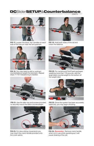
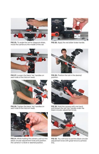
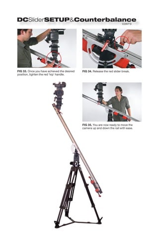
SlideShare a Scribd company logo
Contents: Large     Case


           Rail System (1)


                                   Ears (2)


                      Feet (2)


           Feet Platforms (4)

                                      Mini Jib Parallelogram Arm (1)
              Crank Handle(1)


Contents: Small     Case
                                                             Monitor
                                                             Mounting
                                                             Rod (1)
Right Angle
Plate (1)
                                                             Fulcrum
                                                             Locking
                                                             Handle
                                                             (Black)


                                                        Allen Tools (3)
                                                        M4, M2.5 & M2

    Small Counterbalance                      Large Counterbalance
    Weights (Red)                             Weight (Black)
    (8) Large 2.25 lbs (1 kg)                 5.75 lbs (2.7 kg)
    (2) Medium 1.1 lbs (.5 kg)
    (2) Small .45 lbs (.2 kg)       Fulcrum Head (1)
    (2) Precision .2 lbs (.1 kg)
IMPORTANT:
                           You must complete
                           the counterbalance
                               procedure in the
                            first section of this
                                  manual before
                                completing this
                                          setup.


FIG 1. A flat plate fluid head and heavy-duty       FIG 2. Insert the fulcrum head and level it
(80 lb min / 36 kg) tripod with 100mm bowl          accordingly.
must be used with this system.


FIG 3. Secure the fulcrum head using the            FIG 4. Remove the black ‘kip’ handles
long black handle with female threaded hole.        on each side fulcrum.


FIG 5. Insert the rail onto the top of the          FIG 6. The ‘smile’ quadrant of the rail system
fulcrum with the red ‘kip’ handle on the            should be on the outside of the fulcrum head.
same side as the Matthews script.


FIG 7. Secure the rail system with the two          FIG 8. Mount your flat plate fluid head onto
black ‘kip’ handles.                                the 3/8” threaded stud on the rail platform.
FIG 9. Tighten the flat plate fluid head to the   FIG 10. Mount your camera package to the
rail platform until it is secure.                 fluid head (camera package and fluid head
                                                  not to exceed 25 lbs).


FIG 11. Remove the black nuts and the red         FIG 12. Add counterweight to the sled
protective balls from the counterbalance          to equal the weight of the camera and fluid
sled.                                             head package.


FIG 13. Reattach the black nuts for weight        FIG 14. Loosen the red slider brake.
security.


FIG 15. Slide the camera away from                FIG 16. Tighten the red slider brake
the center.                                       and place red protective balls above the
                                                  counterweight.
CONT’D


FIG 17. Loosen the black ‘kip’ handles on each   FIG 18. Hold both sides of the rail and
side of the fulcrum near the rail quadrant.      check the balance.


FIG 19. You may need to add or subtract          FIG 20. For camera and fluid head packages
counterbalance weight for precision. Repeat      weighing more than 17.6 pounds, add the
steps 11-18 if rebalancing is needed.            large black counterweight to the bottom of
                                                 the weight sled.


FIG 21. Use the allen key and screws provided    FIG 22. Once the system has been accurately
to securely mount the black counterweight.       balanced, you may begin shooting.


FIG 23. For slow sliding movements you           FIG 24. Remember: Remove crank handle
may insert the crank handle provided onto        when not in use while operating as it will
the crank spline.                                cause shaking of the rail.
FIG 25. To angle the rail for diagonal slides,   FIG 26. Apply the red slider brake handle.
move the camera to the middle of the rail.


FIG 27. Loosen the black ‘kip’ handles on        FIG 28. Position the rail in the desired
each side of the fulcrum head.                   position.


FIG 29. Tighten the black ‘kip’ handles on       FIG 30. Hold the camera with one hand
each side of the fulcrum head.                   and loosen the red ‘kip’ handle under the
                                                 black circular adjustment knob.


FIG 31. While holding the camera, pull out the   FIG 32. You will have to pull the black circular
black circular adjustment knob and position      adjustment knob with great force to achieve
the camera in a level or desired position.       this.
CONT’D


FIG 33. Once you have achieved the desired   FIG 34. Release the red slider break.
position, tighten the red ‘kip’ handle.


                                             FIG 35. You are now ready to move the
                                             camera up and down the rail with ease.
FIG 36. Insert the threaded platforms               FIG 37. Attach the feet to each end of
into the feet.                                      the rail using the screws provided.


                                                    IMPORTANT:
                                                    You must complete the counterbalance
                                                    procedure in the first section of this manual
                                                    before completing this setup.


FIG 38. Each end of the rail should have one
foot and two threaded platforms. Adjust
threaded platforms to desired height.


                                    FIG 39. Adjust threaded platforms to the desired height.


FIG 40. The threaded platforms have swiveling feet, which
allows the user to change the angle of the low profile slider.
IMPORTANT:
                                        You must complete the counterbalance
                                        procedure in the first section of this manual
                                        before completing this setup.


                                                   FIG 42. Add one of the feet with the threaded
                                                   platforms to the side opposite the crank
                                                   spline. Use the holes on the foot labeled
                                                   ‘Vertical Feet’ and make sure the long side of
                                                   the foot is facing outward.


                                                   FIG 43. Add the two ears to the base of the
                                                   fulcrum using the threaded knobs. Make sure
                                                   the rubber disks on the ears face outward.
FIG 41. Complete vertical tower configuration.


FIG 44. Add the rail in the vertical position       FIG 45. To mount the right angle plate, line
using the black ‘kip’ handles from the              the holes on the short side of the plate with
fulcrum, threading them through the slider          the hole pattern on the slider platform.
quadrant and into the ears previously
mounted on the fulcrum.
FIG 46. The long side of the plate should
face up. Use the screws provided to securely
mount the plate.


                                                   FIG 52. Complete tightening process
                                                   with red handle, ensure that the teeth
FIG 47. Mount your flat plate fluid head           in the middle of the camera platform
to the top of the right angle plate using the      are fully disengaged and that the
screw provided.                                    nipples on the telescoping lever
                                                   meet the holes on the fulcrum


FIG 48. Mount your camera package to            FIG 49. Completed vertical tower
the fluid head to complete vertical tower       configuration.
configuration.
IMPORTANT: You must complete the counterbalance procedure
in the first section of this manual before completing this setup.


FIG 50. Level the rail and the counter-           FIG 51. With both black ‘kip’ handles
balanced fluid head and camera package.           tightened on each side of the fulcrum head,
                                                  slide the camera package to the end of the
                                                  rail opposite the crank spline.


FIG 52. Tighten the slider brake once the
camera has been moved to the end of the rail.     FIG 53. Install the parallelogram arm located
                                                  in the large case by completing the following.


FIG 54. Install the end of the parallelogram
arm opposite the small lever with the red         FIG 55. Turn the knob on the focal point
‘kip’ handle onto the focal point adjustment      adjustment to reposition the end of the
located on the fulcrum head.                      parallelogram arm so that it is on the top
                                                  of the adjustment.


FIG 56. Attach the opposite side of the
parallelogram arm to the camera platform          FIG 57. The lever with red ‘kip’ handle should
by inserting the red ‘kip’ handle bolt into the   be perpendicular to the rail. This will ensure
threaded hole. Do not thread all the way.         parallel camera movement to the ground.
FIG 58. You may need to adjust the length of      FIG 59. Use the adjusting hand grip on the
the parallelogram arm to adjust framing.          parallelogram arm to accomplish this.


FIG 60. Complete tightening process with          FIG 61. Release the red ‘kip’ handle
the red ‘kip’ handle. Ensure the teeth in         underneath the black adjustment knob.
the middle of the camera platform are fully
disengaged and that the nipples on the arm’s
lever have fully met the holes on the platform.


FIG 62. Release the black ‘kip’ handles on        FIG 63. As the mini jib moves up and down,
each side of the fulcrum head to activate the     the camera should stay parallel with the
mini jib function.                                ground.
CONT’D


FIG 64. If you desire to keep an object within   FIG 65. The mini jib will now focus on the
the camera frame, reposition the focal point     framed object as the system elevates and
adjustment to the bottom.                        descends. You may need to use the adjusting
                                                 hand grip depending on your distance
                                                 between the camera and the point
                                                 of interest.


FIG 66. Loosening up the fulcrum brake           FIG 67. To disassemble the mini jib, tighten
handles will allow 360 degree rotations          the red ‘kip’ handle underneath the black
around the vertical access of the tripod.        adjustment knob.


FIG 68. Remove the parallelograms lever by       FIG 69. Once the parallelogram arm has
releasing the red ‘kip’ handle.                  been removed from the camera platform side,
                                                 remove the opposite end on the fulcrum head.
FIG 70. To mount a monitor on the fulcrum,        FIG 71. Attach the black mounting rod by
attach one of the ears with the rubber disk       screwing it onto the ear.
facing out.


FIG 72. Mount your ball head of choice to the
1/4”-20” end of the rod.


   FIG 73. Add the monitor to the ball head and lock it
   off to desired position.
FIG 74. The counterweight rods            FIG 75. Affix the optional stepper
must be protected with the red balls      motor to the crank spline with the
provided for safety purposes for          four thumbscrews provided.
those in close proximity to the
DC-Slider.


FIG 76. The stepper motor is           FIG 77. The wheel tension is set
operated with a microprocessor,        by the manufacturer. With time and
allowing the user to operate the       frequency, it may be necessary to
slider and tower configurations.       adjust the tension with the M2.5
Time lapse, manual movement and        allen key provided in the system.
programmable repeated movements
are possible with the use of these
accessories.
Liability: The DC-Slider should only be operated by qualified personnel. The DC-Slider
braking system was designed to be used when the system has been precision counterbalanced. The
DC-Slider is not meant to be used with loads over twenty five pounds. Exceeding this weight
capacity may trigger system malfunction, which may result in injury, death or may damage
equipment affixed or within close proximity of the DC-Slider. Matthews has made diligent
effort to illustrate and describe the products and components in this manual accurately
however, illustrations and descriptions including descriptions of dimensions and weight, are
for identification purposes only, and are not warranties that the products will conform to the
illustrations or descriptions. Descriptions of output and other performance levels of our product
are based on normal use conditions, as well as installation and operation by qualified persons.
However, these descriptions are not warranties. Product performance or output may also be
affected by state and local regulations on sales, construction, installation and/or use of products.
All weights are approximate and have been rounded to the nearest quarter pound if under ten
pounds and to the nearest one half pound if over ten pounds. In no event shall our company,
officers, directors, employees or agents be responsible for any direct, indirect, punitive, special,
incidental or consequential damages, however, it arises, whether in an action for negligence
or some other action, or arising out of or in connection with the comments or advice provided by
this application.


Warranty: Matthews Studio Equipment products are warranted against defects for one year
from date of purchase. Within this period of time Matthews will repair it without charge for labor
or parts. Warranty does not cover transportation costs nor does it cover a product subjected to
misuse or accidental damage. Warranty repairs are subjected to inspection and evaluation by
Matthews Studio Equipment.
DC Slider Instructions Manual

More Related Content

Similar to DC Slider Instructions Manual

Hyster d138 (n40 fr) forklift service repair manual
Hyster d138 (n40 fr) forklift service repair manualHyster d138 (n40 fr) forklift service repair manual
Hyster d138 (n40 fr) forklift service repair manual
fusjfskeekemm
 
Hyster d138 (n50 fa) forklift service repair manual
Hyster d138 (n50 fa) forklift service repair manualHyster d138 (n50 fa) forklift service repair manual
Hyster d138 (n50 fa) forklift service repair manual
fujsjefkksekmm
 
Hyster d138 (n45 fr) forklift service repair manual
Hyster d138 (n45 fr) forklift service repair manualHyster d138 (n45 fr) forklift service repair manual
Hyster d138 (n45 fr) forklift service repair manual
fujsjfkksekmme
 
Hyster d138 (n40 fr) forklift service repair manual
Hyster d138 (n40 fr) forklift service repair manualHyster d138 (n40 fr) forklift service repair manual
Hyster d138 (n40 fr) forklift service repair manual
ufjjdkksmeme
 
Hyster d138 (n40 fr) forklift service repair manual
Hyster d138 (n40 fr) forklift service repair manualHyster d138 (n40 fr) forklift service repair manual
Hyster d138 (n40 fr) forklift service repair manual
udfjjjdkksmmd
 
Hyster d138 (n45 fr) forklift service repair manual
Hyster d138 (n45 fr) forklift service repair manualHyster d138 (n45 fr) forklift service repair manual
Hyster d138 (n45 fr) forklift service repair manual
soeldksejdksem
 
Hyster d138 (n40 fr) forklift service repair manual
Hyster d138 (n40 fr) forklift service repair manualHyster d138 (n40 fr) forklift service repair manual
Hyster d138 (n40 fr) forklift service repair manual
fjsekksmemm
 
Hyster d138 (n45 fr) forklift service repair manual
Hyster d138 (n45 fr) forklift service repair manualHyster d138 (n45 fr) forklift service repair manual
Hyster d138 (n45 fr) forklift service repair manual
udjjdjkksmme
 
Hyster d138 (n50 fa) forklift service repair manual
Hyster d138 (n50 fa) forklift service repair manualHyster d138 (n50 fa) forklift service repair manual
Hyster d138 (n50 fa) forklift service repair manual
fusjfjskekmsme
 
Mitra Stats Project Final
Mitra Stats Project FinalMitra Stats Project Final
Mitra Stats Project Final
shonabunch1
 
Mobile Wire Shelving Installation Instructions
Mobile Wire Shelving Installation InstructionsMobile Wire Shelving Installation Instructions
Mobile Wire Shelving Installation Instructions
Installation Manuals - Southwest Solutions Group
 
10 x 30 Frame Tent Installation Instructions
10 x 30 Frame Tent Installation Instructions 10 x 30 Frame Tent Installation Instructions
10 x 30 Frame Tent Installation Instructions
celinatent
 
Xtend Dual Screen Crossbar Monitor Arm Assembly Instructions
Xtend Dual Screen Crossbar Monitor Arm Assembly InstructionsXtend Dual Screen Crossbar Monitor Arm Assembly Instructions
Xtend Dual Screen Crossbar Monitor Arm Assembly Instructions
iMovR
 
iMovR Xtend Monitor Arm Manual
iMovR Xtend Monitor Arm ManualiMovR Xtend Monitor Arm Manual
iMovR Xtend Monitor Arm Manual
iMovR
 
95ZJ_8L.PDF
95ZJ_8L.PDF95ZJ_8L.PDF
95ZJ_8L.PDF
Åge Færestrand
 
10 x 40 Frame Tent Installation Instructions
10 x 40 Frame Tent Installation Instructions10 x 40 Frame Tent Installation Instructions
10 x 40 Frame Tent Installation Instructions
celinatent
 
Concerto Monitor Arm Manual
Concerto Monitor Arm ManualConcerto Monitor Arm Manual
Concerto Monitor Arm Manual
iMovR
 
10 x 20 Frame Tent Installation Instructions
10 x 20 Frame Tent Installation Instructions10 x 20 Frame Tent Installation Instructions
10 x 20 Frame Tent Installation Instructions
celinatent
 
Installation Manual Aluminum
Installation Manual AluminumInstallation Manual Aluminum
Installation Manual Aluminum
tmpservices01
 
Installation Manual Aluminum
Installation Manual AluminumInstallation Manual Aluminum
Installation Manual Aluminum
tmpservices01
 

Similar to DC Slider Instructions Manual (20)

Hyster d138 (n40 fr) forklift service repair manual
Hyster d138 (n40 fr) forklift service repair manualHyster d138 (n40 fr) forklift service repair manual
Hyster d138 (n40 fr) forklift service repair manual
 
Hyster d138 (n50 fa) forklift service repair manual
Hyster d138 (n50 fa) forklift service repair manualHyster d138 (n50 fa) forklift service repair manual
Hyster d138 (n50 fa) forklift service repair manual
 
Hyster d138 (n45 fr) forklift service repair manual
Hyster d138 (n45 fr) forklift service repair manualHyster d138 (n45 fr) forklift service repair manual
Hyster d138 (n45 fr) forklift service repair manual
 
Hyster d138 (n40 fr) forklift service repair manual
Hyster d138 (n40 fr) forklift service repair manualHyster d138 (n40 fr) forklift service repair manual
Hyster d138 (n40 fr) forklift service repair manual
 
Hyster d138 (n40 fr) forklift service repair manual
Hyster d138 (n40 fr) forklift service repair manualHyster d138 (n40 fr) forklift service repair manual
Hyster d138 (n40 fr) forklift service repair manual
 
Hyster d138 (n45 fr) forklift service repair manual
Hyster d138 (n45 fr) forklift service repair manualHyster d138 (n45 fr) forklift service repair manual
Hyster d138 (n45 fr) forklift service repair manual
 
Hyster d138 (n40 fr) forklift service repair manual
Hyster d138 (n40 fr) forklift service repair manualHyster d138 (n40 fr) forklift service repair manual
Hyster d138 (n40 fr) forklift service repair manual
 
Hyster d138 (n45 fr) forklift service repair manual
Hyster d138 (n45 fr) forklift service repair manualHyster d138 (n45 fr) forklift service repair manual
Hyster d138 (n45 fr) forklift service repair manual
 
Hyster d138 (n50 fa) forklift service repair manual
Hyster d138 (n50 fa) forklift service repair manualHyster d138 (n50 fa) forklift service repair manual
Hyster d138 (n50 fa) forklift service repair manual
 
Mitra Stats Project Final
Mitra Stats Project FinalMitra Stats Project Final
Mitra Stats Project Final
 
Mobile Wire Shelving Installation Instructions
Mobile Wire Shelving Installation InstructionsMobile Wire Shelving Installation Instructions
Mobile Wire Shelving Installation Instructions
 
10 x 30 Frame Tent Installation Instructions
10 x 30 Frame Tent Installation Instructions 10 x 30 Frame Tent Installation Instructions
10 x 30 Frame Tent Installation Instructions
 
Xtend Dual Screen Crossbar Monitor Arm Assembly Instructions
Xtend Dual Screen Crossbar Monitor Arm Assembly InstructionsXtend Dual Screen Crossbar Monitor Arm Assembly Instructions
Xtend Dual Screen Crossbar Monitor Arm Assembly Instructions
 
iMovR Xtend Monitor Arm Manual
iMovR Xtend Monitor Arm ManualiMovR Xtend Monitor Arm Manual
iMovR Xtend Monitor Arm Manual
 
95ZJ_8L.PDF
95ZJ_8L.PDF95ZJ_8L.PDF
95ZJ_8L.PDF
 
10 x 40 Frame Tent Installation Instructions
10 x 40 Frame Tent Installation Instructions10 x 40 Frame Tent Installation Instructions
10 x 40 Frame Tent Installation Instructions
 
Concerto Monitor Arm Manual
Concerto Monitor Arm ManualConcerto Monitor Arm Manual
Concerto Monitor Arm Manual
 
10 x 20 Frame Tent Installation Instructions
10 x 20 Frame Tent Installation Instructions10 x 20 Frame Tent Installation Instructions
10 x 20 Frame Tent Installation Instructions
 
Installation Manual Aluminum
Installation Manual AluminumInstallation Manual Aluminum
Installation Manual Aluminum
 
Installation Manual Aluminum
Installation Manual AluminumInstallation Manual Aluminum
Installation Manual Aluminum
 

Recently uploaded

Part 2 Deep Dive: Navigating the 2024 Slowdown
Part 2 Deep Dive: Navigating the 2024 SlowdownPart 2 Deep Dive: Navigating the 2024 Slowdown
Part 2 Deep Dive: Navigating the 2024 Slowdown
jeffkluth1
 
Building Your Employer Brand with Social Media
Building Your Employer Brand with Social MediaBuilding Your Employer Brand with Social Media
Building Your Employer Brand with Social Media
LuanWise
 
Understanding User Needs and Satisfying Them
Understanding User Needs and Satisfying ThemUnderstanding User Needs and Satisfying Them
Understanding User Needs and Satisfying Them
Aggregage
 
Best Forex Brokers Comparison in INDIA 2024
Best Forex Brokers Comparison in INDIA 2024Best Forex Brokers Comparison in INDIA 2024
Best Forex Brokers Comparison in INDIA 2024
Top Forex Brokers Review
 
Authentically Social by Corey Perlman - EO Puerto Rico
Authentically Social by Corey Perlman - EO Puerto RicoAuthentically Social by Corey Perlman - EO Puerto Rico
Authentically Social by Corey Perlman - EO Puerto Rico
Corey Perlman, Social Media Speaker and Consultant
 
一比一原版新西兰奥塔哥大学毕业证(otago毕业证)如何办理
一比一原版新西兰奥塔哥大学毕业证(otago毕业证)如何办理一比一原版新西兰奥塔哥大学毕业证(otago毕业证)如何办理
一比一原版新西兰奥塔哥大学毕业证(otago毕业证)如何办理
taqyea
 
Authentically Social Presented by Corey Perlman
Authentically Social Presented by Corey PerlmanAuthentically Social Presented by Corey Perlman
Authentically Social Presented by Corey Perlman
Corey Perlman, Social Media Speaker and Consultant
 
Zodiac Signs and Food Preferences_ What Your Sign Says About Your Taste
Zodiac Signs and Food Preferences_ What Your Sign Says About Your TasteZodiac Signs and Food Preferences_ What Your Sign Says About Your Taste
Zodiac Signs and Food Preferences_ What Your Sign Says About Your Taste
my Pandit
 
Dpboss Matka Guessing Satta Matta Matka Kalyan Chart Satta Matka
Dpboss Matka Guessing Satta Matta Matka Kalyan Chart Satta MatkaDpboss Matka Guessing Satta Matta Matka Kalyan Chart Satta Matka
Dpboss Matka Guessing Satta Matta Matka Kalyan Chart Satta Matka
➒➌➎➏➑➐➋➑➐➐Dpboss Matka Guessing Satta Matka Kalyan Chart Indian Matka
 
ikea_woodgreen_petscharity_cat-alogue_digital.pdf
ikea_woodgreen_petscharity_cat-alogue_digital.pdfikea_woodgreen_petscharity_cat-alogue_digital.pdf
ikea_woodgreen_petscharity_cat-alogue_digital.pdf
agatadrynko
 
The Evolution and Impact of OTT Platforms: A Deep Dive into the Future of Ent...
The Evolution and Impact of OTT Platforms: A Deep Dive into the Future of Ent...The Evolution and Impact of OTT Platforms: A Deep Dive into the Future of Ent...
The Evolution and Impact of OTT Platforms: A Deep Dive into the Future of Ent...
ABHILASH DUTTA
 
Creative Web Design Company in Singapore
Creative Web Design Company in SingaporeCreative Web Design Company in Singapore
Creative Web Design Company in Singapore
techboxsqauremedia
 
Creative Web Design Company in Singapore
Creative Web Design Company in SingaporeCreative Web Design Company in Singapore
Creative Web Design Company in Singapore
techboxsqauremedia
 
Call 8867766396 Satta Matka Dpboss Matka Guessing Satta batta Matka 420 Satta...
Call 8867766396 Satta Matka Dpboss Matka Guessing Satta batta Matka 420 Satta...Call 8867766396 Satta Matka Dpboss Matka Guessing Satta batta Matka 420 Satta...
Call 8867766396 Satta Matka Dpboss Matka Guessing Satta batta Matka 420 Satta...
bosssp10
 
Lundin Gold Corporate Presentation - June 2024
Lundin Gold Corporate Presentation - June 2024Lundin Gold Corporate Presentation - June 2024
Lundin Gold Corporate Presentation - June 2024
Adnet Communications
 
The Influence of Marketing Strategy and Market Competition on Business Perfor...
The Influence of Marketing Strategy and Market Competition on Business Perfor...The Influence of Marketing Strategy and Market Competition on Business Perfor...
The Influence of Marketing Strategy and Market Competition on Business Perfor...
Adam Smith
 
-- June 2024 is National Volunteer Month --
-- June 2024 is National Volunteer Month ---- June 2024 is National Volunteer Month --
-- June 2024 is National Volunteer Month --
NZSG
 
Event Report - SAP Sapphire 2024 Orlando - lots of innovation and old challenges
Event Report - SAP Sapphire 2024 Orlando - lots of innovation and old challengesEvent Report - SAP Sapphire 2024 Orlando - lots of innovation and old challenges
Event Report - SAP Sapphire 2024 Orlando - lots of innovation and old challenges
Holger Mueller
 
buy old yahoo accounts buy yahoo accounts
buy old yahoo accounts buy yahoo accountsbuy old yahoo accounts buy yahoo accounts
buy old yahoo accounts buy yahoo accounts
Susan Laney
 
How MJ Global Leads the Packaging Industry.pdf
How MJ Global Leads the Packaging Industry.pdfHow MJ Global Leads the Packaging Industry.pdf
How MJ Global Leads the Packaging Industry.pdf
MJ Global
 

Recently uploaded (20)

Part 2 Deep Dive: Navigating the 2024 Slowdown
Part 2 Deep Dive: Navigating the 2024 SlowdownPart 2 Deep Dive: Navigating the 2024 Slowdown
Part 2 Deep Dive: Navigating the 2024 Slowdown
 
Building Your Employer Brand with Social Media
Building Your Employer Brand with Social MediaBuilding Your Employer Brand with Social Media
Building Your Employer Brand with Social Media
 
Understanding User Needs and Satisfying Them
Understanding User Needs and Satisfying ThemUnderstanding User Needs and Satisfying Them
Understanding User Needs and Satisfying Them
 
Best Forex Brokers Comparison in INDIA 2024
Best Forex Brokers Comparison in INDIA 2024Best Forex Brokers Comparison in INDIA 2024
Best Forex Brokers Comparison in INDIA 2024
 
Authentically Social by Corey Perlman - EO Puerto Rico
Authentically Social by Corey Perlman - EO Puerto RicoAuthentically Social by Corey Perlman - EO Puerto Rico
Authentically Social by Corey Perlman - EO Puerto Rico
 
一比一原版新西兰奥塔哥大学毕业证(otago毕业证)如何办理
一比一原版新西兰奥塔哥大学毕业证(otago毕业证)如何办理一比一原版新西兰奥塔哥大学毕业证(otago毕业证)如何办理
一比一原版新西兰奥塔哥大学毕业证(otago毕业证)如何办理
 
Authentically Social Presented by Corey Perlman
Authentically Social Presented by Corey PerlmanAuthentically Social Presented by Corey Perlman
Authentically Social Presented by Corey Perlman
 
Zodiac Signs and Food Preferences_ What Your Sign Says About Your Taste
Zodiac Signs and Food Preferences_ What Your Sign Says About Your TasteZodiac Signs and Food Preferences_ What Your Sign Says About Your Taste
Zodiac Signs and Food Preferences_ What Your Sign Says About Your Taste
 
Dpboss Matka Guessing Satta Matta Matka Kalyan Chart Satta Matka
Dpboss Matka Guessing Satta Matta Matka Kalyan Chart Satta MatkaDpboss Matka Guessing Satta Matta Matka Kalyan Chart Satta Matka
Dpboss Matka Guessing Satta Matta Matka Kalyan Chart Satta Matka
 
ikea_woodgreen_petscharity_cat-alogue_digital.pdf
ikea_woodgreen_petscharity_cat-alogue_digital.pdfikea_woodgreen_petscharity_cat-alogue_digital.pdf
ikea_woodgreen_petscharity_cat-alogue_digital.pdf
 
The Evolution and Impact of OTT Platforms: A Deep Dive into the Future of Ent...
The Evolution and Impact of OTT Platforms: A Deep Dive into the Future of Ent...The Evolution and Impact of OTT Platforms: A Deep Dive into the Future of Ent...
The Evolution and Impact of OTT Platforms: A Deep Dive into the Future of Ent...
 
Creative Web Design Company in Singapore
Creative Web Design Company in SingaporeCreative Web Design Company in Singapore
Creative Web Design Company in Singapore
 
Creative Web Design Company in Singapore
Creative Web Design Company in SingaporeCreative Web Design Company in Singapore
Creative Web Design Company in Singapore
 
Call 8867766396 Satta Matka Dpboss Matka Guessing Satta batta Matka 420 Satta...
Call 8867766396 Satta Matka Dpboss Matka Guessing Satta batta Matka 420 Satta...Call 8867766396 Satta Matka Dpboss Matka Guessing Satta batta Matka 420 Satta...
Call 8867766396 Satta Matka Dpboss Matka Guessing Satta batta Matka 420 Satta...
 
Lundin Gold Corporate Presentation - June 2024
Lundin Gold Corporate Presentation - June 2024Lundin Gold Corporate Presentation - June 2024
Lundin Gold Corporate Presentation - June 2024
 
The Influence of Marketing Strategy and Market Competition on Business Perfor...
The Influence of Marketing Strategy and Market Competition on Business Perfor...The Influence of Marketing Strategy and Market Competition on Business Perfor...
The Influence of Marketing Strategy and Market Competition on Business Perfor...
 
-- June 2024 is National Volunteer Month --
-- June 2024 is National Volunteer Month ---- June 2024 is National Volunteer Month --
-- June 2024 is National Volunteer Month --
 
Event Report - SAP Sapphire 2024 Orlando - lots of innovation and old challenges
Event Report - SAP Sapphire 2024 Orlando - lots of innovation and old challengesEvent Report - SAP Sapphire 2024 Orlando - lots of innovation and old challenges
Event Report - SAP Sapphire 2024 Orlando - lots of innovation and old challenges
 
buy old yahoo accounts buy yahoo accounts
buy old yahoo accounts buy yahoo accountsbuy old yahoo accounts buy yahoo accounts
buy old yahoo accounts buy yahoo accounts
 
How MJ Global Leads the Packaging Industry.pdf
How MJ Global Leads the Packaging Industry.pdfHow MJ Global Leads the Packaging Industry.pdf
How MJ Global Leads the Packaging Industry.pdf
 

DC Slider Instructions Manual

  • 1.
  • 2.
  • 3. Contents: Large Case Rail System (1) Ears (2) Feet (2) Feet Platforms (4) Mini Jib Parallelogram Arm (1) Crank Handle(1) Contents: Small Case Monitor Mounting Rod (1) Right Angle Plate (1) Fulcrum Locking Handle (Black) Allen Tools (3) M4, M2.5 & M2 Small Counterbalance Large Counterbalance Weights (Red) Weight (Black) (8) Large 2.25 lbs (1 kg) 5.75 lbs (2.7 kg) (2) Medium 1.1 lbs (.5 kg) (2) Small .45 lbs (.2 kg) Fulcrum Head (1) (2) Precision .2 lbs (.1 kg)
  • 4. IMPORTANT: You must complete the counterbalance procedure in the first section of this manual before completing this setup. FIG 1. A flat plate fluid head and heavy-duty FIG 2. Insert the fulcrum head and level it (80 lb min / 36 kg) tripod with 100mm bowl accordingly. must be used with this system. FIG 3. Secure the fulcrum head using the FIG 4. Remove the black ‘kip’ handles long black handle with female threaded hole. on each side fulcrum. FIG 5. Insert the rail onto the top of the FIG 6. The ‘smile’ quadrant of the rail system fulcrum with the red ‘kip’ handle on the should be on the outside of the fulcrum head. same side as the Matthews script. FIG 7. Secure the rail system with the two FIG 8. Mount your flat plate fluid head onto black ‘kip’ handles. the 3/8” threaded stud on the rail platform.
  • 5. FIG 9. Tighten the flat plate fluid head to the FIG 10. Mount your camera package to the rail platform until it is secure. fluid head (camera package and fluid head not to exceed 25 lbs). FIG 11. Remove the black nuts and the red FIG 12. Add counterweight to the sled protective balls from the counterbalance to equal the weight of the camera and fluid sled. head package. FIG 13. Reattach the black nuts for weight FIG 14. Loosen the red slider brake. security. FIG 15. Slide the camera away from FIG 16. Tighten the red slider brake the center. and place red protective balls above the counterweight.
  • 6. CONT’D FIG 17. Loosen the black ‘kip’ handles on each FIG 18. Hold both sides of the rail and side of the fulcrum near the rail quadrant. check the balance. FIG 19. You may need to add or subtract FIG 20. For camera and fluid head packages counterbalance weight for precision. Repeat weighing more than 17.6 pounds, add the steps 11-18 if rebalancing is needed. large black counterweight to the bottom of the weight sled. FIG 21. Use the allen key and screws provided FIG 22. Once the system has been accurately to securely mount the black counterweight. balanced, you may begin shooting. FIG 23. For slow sliding movements you FIG 24. Remember: Remove crank handle may insert the crank handle provided onto when not in use while operating as it will the crank spline. cause shaking of the rail.
  • 7. FIG 25. To angle the rail for diagonal slides, FIG 26. Apply the red slider brake handle. move the camera to the middle of the rail. FIG 27. Loosen the black ‘kip’ handles on FIG 28. Position the rail in the desired each side of the fulcrum head. position. FIG 29. Tighten the black ‘kip’ handles on FIG 30. Hold the camera with one hand each side of the fulcrum head. and loosen the red ‘kip’ handle under the black circular adjustment knob. FIG 31. While holding the camera, pull out the FIG 32. You will have to pull the black circular black circular adjustment knob and position adjustment knob with great force to achieve the camera in a level or desired position. this.
  • 8. CONT’D FIG 33. Once you have achieved the desired FIG 34. Release the red slider break. position, tighten the red ‘kip’ handle. FIG 35. You are now ready to move the camera up and down the rail with ease.
  • 9. FIG 36. Insert the threaded platforms FIG 37. Attach the feet to each end of into the feet. the rail using the screws provided. IMPORTANT: You must complete the counterbalance procedure in the first section of this manual before completing this setup. FIG 38. Each end of the rail should have one foot and two threaded platforms. Adjust threaded platforms to desired height. FIG 39. Adjust threaded platforms to the desired height. FIG 40. The threaded platforms have swiveling feet, which allows the user to change the angle of the low profile slider.
  • 10. IMPORTANT: You must complete the counterbalance procedure in the first section of this manual before completing this setup. FIG 42. Add one of the feet with the threaded platforms to the side opposite the crank spline. Use the holes on the foot labeled ‘Vertical Feet’ and make sure the long side of the foot is facing outward. FIG 43. Add the two ears to the base of the fulcrum using the threaded knobs. Make sure the rubber disks on the ears face outward. FIG 41. Complete vertical tower configuration. FIG 44. Add the rail in the vertical position FIG 45. To mount the right angle plate, line using the black ‘kip’ handles from the the holes on the short side of the plate with fulcrum, threading them through the slider the hole pattern on the slider platform. quadrant and into the ears previously mounted on the fulcrum.
  • 11. FIG 46. The long side of the plate should face up. Use the screws provided to securely mount the plate. FIG 52. Complete tightening process with red handle, ensure that the teeth FIG 47. Mount your flat plate fluid head in the middle of the camera platform to the top of the right angle plate using the are fully disengaged and that the screw provided. nipples on the telescoping lever meet the holes on the fulcrum FIG 48. Mount your camera package to FIG 49. Completed vertical tower the fluid head to complete vertical tower configuration. configuration.
  • 12. IMPORTANT: You must complete the counterbalance procedure in the first section of this manual before completing this setup. FIG 50. Level the rail and the counter- FIG 51. With both black ‘kip’ handles balanced fluid head and camera package. tightened on each side of the fulcrum head, slide the camera package to the end of the rail opposite the crank spline. FIG 52. Tighten the slider brake once the camera has been moved to the end of the rail. FIG 53. Install the parallelogram arm located in the large case by completing the following. FIG 54. Install the end of the parallelogram arm opposite the small lever with the red FIG 55. Turn the knob on the focal point ‘kip’ handle onto the focal point adjustment adjustment to reposition the end of the located on the fulcrum head. parallelogram arm so that it is on the top of the adjustment. FIG 56. Attach the opposite side of the parallelogram arm to the camera platform FIG 57. The lever with red ‘kip’ handle should by inserting the red ‘kip’ handle bolt into the be perpendicular to the rail. This will ensure threaded hole. Do not thread all the way. parallel camera movement to the ground.
  • 13. FIG 58. You may need to adjust the length of FIG 59. Use the adjusting hand grip on the the parallelogram arm to adjust framing. parallelogram arm to accomplish this. FIG 60. Complete tightening process with FIG 61. Release the red ‘kip’ handle the red ‘kip’ handle. Ensure the teeth in underneath the black adjustment knob. the middle of the camera platform are fully disengaged and that the nipples on the arm’s lever have fully met the holes on the platform. FIG 62. Release the black ‘kip’ handles on FIG 63. As the mini jib moves up and down, each side of the fulcrum head to activate the the camera should stay parallel with the mini jib function. ground.
  • 14. CONT’D FIG 64. If you desire to keep an object within FIG 65. The mini jib will now focus on the the camera frame, reposition the focal point framed object as the system elevates and adjustment to the bottom. descends. You may need to use the adjusting hand grip depending on your distance between the camera and the point of interest. FIG 66. Loosening up the fulcrum brake FIG 67. To disassemble the mini jib, tighten handles will allow 360 degree rotations the red ‘kip’ handle underneath the black around the vertical access of the tripod. adjustment knob. FIG 68. Remove the parallelograms lever by FIG 69. Once the parallelogram arm has releasing the red ‘kip’ handle. been removed from the camera platform side, remove the opposite end on the fulcrum head.
  • 15. FIG 70. To mount a monitor on the fulcrum, FIG 71. Attach the black mounting rod by attach one of the ears with the rubber disk screwing it onto the ear. facing out. FIG 72. Mount your ball head of choice to the 1/4”-20” end of the rod. FIG 73. Add the monitor to the ball head and lock it off to desired position.
  • 16. FIG 74. The counterweight rods FIG 75. Affix the optional stepper must be protected with the red balls motor to the crank spline with the provided for safety purposes for four thumbscrews provided. those in close proximity to the DC-Slider. FIG 76. The stepper motor is FIG 77. The wheel tension is set operated with a microprocessor, by the manufacturer. With time and allowing the user to operate the frequency, it may be necessary to slider and tower configurations. adjust the tension with the M2.5 Time lapse, manual movement and allen key provided in the system. programmable repeated movements are possible with the use of these accessories.
  • 17. Liability: The DC-Slider should only be operated by qualified personnel. The DC-Slider braking system was designed to be used when the system has been precision counterbalanced. The DC-Slider is not meant to be used with loads over twenty five pounds. Exceeding this weight capacity may trigger system malfunction, which may result in injury, death or may damage equipment affixed or within close proximity of the DC-Slider. Matthews has made diligent effort to illustrate and describe the products and components in this manual accurately however, illustrations and descriptions including descriptions of dimensions and weight, are for identification purposes only, and are not warranties that the products will conform to the illustrations or descriptions. Descriptions of output and other performance levels of our product are based on normal use conditions, as well as installation and operation by qualified persons. However, these descriptions are not warranties. Product performance or output may also be affected by state and local regulations on sales, construction, installation and/or use of products. All weights are approximate and have been rounded to the nearest quarter pound if under ten pounds and to the nearest one half pound if over ten pounds. In no event shall our company, officers, directors, employees or agents be responsible for any direct, indirect, punitive, special, incidental or consequential damages, however, it arises, whether in an action for negligence or some other action, or arising out of or in connection with the comments or advice provided by this application. Warranty: Matthews Studio Equipment products are warranted against defects for one year from date of purchase. Within this period of time Matthews will repair it without charge for labor or parts. Warranty does not cover transportation costs nor does it cover a product subjected to misuse or accidental damage. Warranty repairs are subjected to inspection and evaluation by Matthews Studio Equipment.