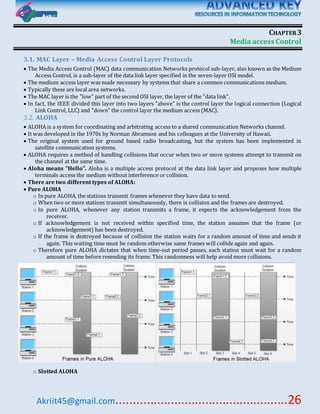
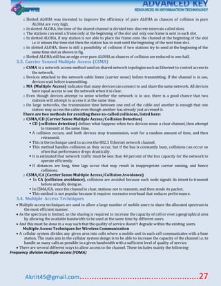
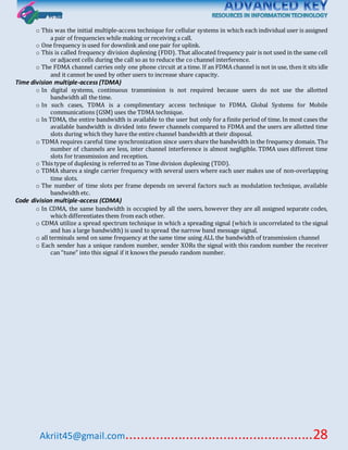
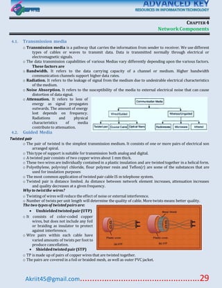
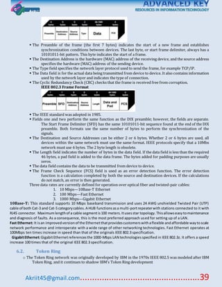
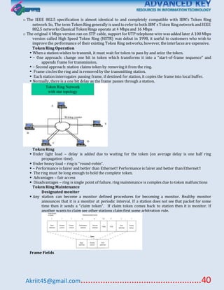
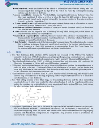
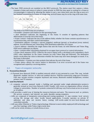
SlideShare a Scribd company logo
1 of 53
Akriit45@gmail.com..................................................1
CONTENTS
Data Communications...........................................................................................................................................3
1.1. Data ...................................................................................................................................................................3
1.2. Communication..................................................................................................................................................3
1.3. Network.............................................................................................................................................................3
1.4. Signal .................................................................................................................................................................3
1.5. Circuit.................................................................................................................................................................3
1.6. Channel..............................................................................................................................................................3
1.7. Multi-Channeling................................................................................................................................................3
1.8. Transmission Modes...........................................................................................................................................4
1.9. Taxonomy of Transmission..................................................................................................................................4
1.10. Parity Check (Asynchronous Data Error Detection).............................................................................................6
1.11. Cyclic Redundancy Check (Synchronous Data Error Detection) ...........................................................................6
1.12. Checksum Error Detection.................................................................................................................................7
1.13. Hamming Coding Technique for Error Correction ...............................................................................................7
1.14. Flow Control .....................................................................................................................................................8
1.15. Piggybacking.....................................................................................................................................................9
1.16. Congestion control............................................................................................................................................9
1.17. Multiplexing.....................................................................................................................................................9
1.18. Baseband v/s Broadband ................................................................................................................................11
1.19. Spread Spectrum ............................................................................................................................................12
1.20. Modulation.....................................................................................................................................................12
1.21. Encoding Techniques.......................................................................................................................................14
1.22. Digital data to Digital Signals Encoding ............................................................................................................14
1.23. Classification of Modems ................................................................................................................................15
1.24. Modem Protocols ...........................................................................................................................................16
1.25. Digital Subscriber Loop (DSL)...........................................................................................................................17
Communication Network Fundamentals............................................................................................................19
2.1. Switching Techniques........................................................................................................................................19
2.2. Open Systems Interconnection (OSI) Model.......................................................................................................21
2.3. Internet Protocol Suite (TCP/IP Model)..............................................................................................................23
Akriit45@gmail.com..................................................2
2.4. LAN topologies.................................................................................................................................................23
Media access Control ..........................................................................................................................................26
3.1. MAC Layer – Media Access Control Layer Protocols ...........................................................................................26
3.2. ALOHA..............................................................................................................................................................26
3.3. Carrier Sensed Multiple Access (CSMA) .............................................................................................................27
3.4. Multiple Access Techniques ..............................................................................................................................27
Network Components..........................................................................................................................................29
4.1. Transmission media......................................................................................................................................29
4.2. Guided Media..............................................................................................................................................29
4.3. Unguided Media...........................................................................................................................................31
4.4. Networking Components and Devices...........................................................................................................33
Link Control and MAC Protocols .........................................................................................................................35
5.1. Data link control (DLC)..................................................................................................................................35
5.2. Framing: ......................................................................................................................................................35
5.3. Flow and Error Control .................................................................................................................................35
5.4. HDLC............................................................................................................................................................37
LAN.......................................................................................................................................................................38
6.1. Ethernet.......................................................................................................................................................38
6.2. Token Ring...................................................................................................................................................39
6.3. FDDI.............................................................................................................................................................41
6.4. Types of computer networks ........................................................................................................................42
WAN.....................................................................................................................................................................45
7.1. Network Routing..........................................................................................................................................45
7.2. Routing Methods................................................................................................Error! Bookmarknot defined.
7.3. IP - The Internet Protocol..............................................................................................................................45
7.4. Network layer protocols..............................................................................................................................47
7.5. Transport layer.............................................................................................................................................48
7.6. USER DATAGRAM PROTOCOL.......................................................................................................................49
Application Protocol............................................................................................................................................50
8.1. CLIENT- SERVER MODEL................................................................................................................................50
8.2. APPLICATION PROTOCOLS............................................................................................................................50
Akriit45@gmail.com..................................................3
CHAPTER1
Data Communications
1.1.Data
 Data is raw material that contains the collection of facts.
 Data refers to information presented in whatever form is agreed upon by the parties creating and
using the data.
o Digital Data: Digital data is stored ones and zeros, which may represent number of way.
 A charged portion 1
 An Uncharged portion 0
o Analog Data: Analog data is that is represented in physical way.
 Records and cassette tapes are forms of analog data storage.
 Printed documents are constructed analog as well.
1.2.Communication
 Communication is the exchange of data between two devices via some form of transmission medium
such as a wire cable.
1.3.Network
 A Network is a set of devise (often referred to as nodes) connected by communication links.
o Node: A node can be a computer, printer, or any other device capable of sending and / or
receiving data generated by other nodes on the network.
o Link: A link can be a cable, air, optical fiber, or any medium which can transport a signal carrying
information
1.4.Signal
 A signal is an electronic current or electromagnetic fields used to convey data from one place to
another.
1.5.Circuit
 A Circuit is path over which data, voice or other signal can pass, between two computers or a terminal
and a computer.
1.6.Channel
 A portion of a bandwidth used for transmitting data
o Bandwidth: A range of frequencies within a given band.
 A band of frequencies used in radio and television transmission, especially used by a particular
station.
 A separate path through which signal can flow
1.7.Multi-Channeling
 Total media capacity or bandwidth can be divided into multiple channels.
 The Passes of multiple signal over a single media
Akriit45@gmail.com..................................................4
 Multi-channeling used mainly in broadband transmission.
1.8.Transmission Modes
Item Simplex Half Duplex Full Duplex
Direction of
Transmission of
Message
Communication in
one directional only
(Uni-Directional)
Both ways but transmission of
communication is only in one
direction at time(Bi-
Directional)
Communication in both
direction simultaneously
( Omni-Directional)
Confirmation Not Possible Possible but slow Possible
Number of
wires
Two Two Four
Cost Cheapest Average Costliest
Example T.V and Radio Hard Disk to Memory Telephonic
Communication
Efficiency Low Medium High
1.9. Taxonomy of Transmission
 A transmission mode is the manner in which data is sent to over the underlying medium
Transmission modes can be divided into two Fundamental categories:
 Serial Transmission
o Serial Transmission sends one bit at a time.
o Serials networks can be extended over long distanced at less cost,
Akriit45@gmail.com..................................................5
o using only one physical wire means that there is never a timing problem caused by one wire being
slightly longer than another
 Parallel Transmission
o Parallel transmission allows transfers of multiple data bits at the same time over separate media.
o It is used with a wired medium
o The signals on all wires are synchronized so that a bit travels across each of the wires at precisely
the same time
o a parallel interface usually contains other wires that allow the sender and receiver to coordinate
o to make installation and troubleshooting easy, the wires are placed in a single physical cable
A parallel mode of transmission has two chief advantages:
 High speed--it can send N bits at the same time.
 It can match the speed of the underlying hardware
Asynchronous Transmission Synchronous Transmission
The senders and receivers clocks are not
Synchronized.
The senders and the receiver’s clocks are synchronized.
The sender sends only one character at a time The sender sends a packet of data at a time.
Each character needs a start bit and a stop bit. Synchronization is achieved by sending a ‘start’ frame
and a ‘stop’ frames that required with up to 8Kb of data
in the packet of data.
There can be idle time between each character. There can be idle time between each frame.
It is a slow and inefficient method of data
transmission.
It is a more efficient method of transmission.
It is an inexpensive method for low speed
transmission.
Asynchronous has a much higher overhead.
Isochronous Transmission
 Combines features of an asynchronous and synchronous data transfer system.
 Isochronous transmission is designed to provide steady bit flow for multimedia applications.
o Steady flow: when flow do not change with time.
 Isochronous networks are designed to accept and send data at a fixed rate, R.
Akriit45@gmail.com..................................................6
 This is ideal when delivering such data at a steady rate is essential (jitter is minimized).
o Jitter: unwanted variation in an electronic or optical signal.
 Network interface is set to transmit/receive exactly R bits per second
Example: An isochronous mechanism designed to transfer voice operates at a rate of 64,000 bps:
o A sender must generate digitized audio continuously.
o A receiver must be able to accept and play the stream at 64,000 bps
1.10.Parity Check (Asynchronous Data Error Detection)
 Used in Asynchronous transmission.
 Detects any errors in each character being sent.
 A bit in each byte is set aside as the parity bit.
o In even parity, the bit is set to 1 or 0 to ensure an even number of 1’s.
o In odd parity, the bit is set to 1 or 0 to ensure and odd number of 1’s.
 The receiving system checks the system being used and the number of 1’s
 Both Telex and Teletype networks employ this method.
 An error-correction process used with asynchronous data stream called Longitudinal Redundancy
Check (LRC) makes use of the Parity process.
For Example: Sender Sent word Help!
0000100
0010100
0010000-->Comparison results because a 1 indicate
the bad bit position.
The detection of a bad parity bit in the ‘l’ character
designated the location of an error in that character. As
a result of comparison of the LRC, bit 3 of that
character is detected as incorrectand wouldbe
inverted to yield the correctedcharacter.
1.11.Cyclic Redundancy Check (Synchronous Data Error Detection)
 The difference here is that the block of data is treated as one (very large) binary number.
 This is then divided by an Integer agreed between the sender and receiver.
 The Remainder only from the calculation is sent along with the data.
 The receiver can perform the same calculation and request re-transmission if there is a discrepancy.
 CRC-16 detects all single and double-bit errors, all errors in bit streams with an odd number of bits in
errors, all errors bursts longer than 16 bits, and 99.9% of error bursts longer than 16 bits.
 CRC-32 detects essentially all errors, which is the primary reason for IEEE selecting this technique for
all LAN standards.
Example 1. The Message frame 110011001011 for which the divisor is 10001.
Answer: Add 0000 (4- bits) with frame 1100110010110000 and divide by 10001.
Sender Receiver
0001001 H  H 0001001
1010011 e e 1010011
0011011 l h 0001011
0000111 p p 0000111
1000010 ! ! 1000010
0000100 Sender’s
LRC
Receiver’s
LRC
0010100
1010011011
10001 1100110010110000
10001
______01011
______00000
_10001
_10001
_______10110
_______10001
Akriit45@gmail.com..................................................7
Exclusive OR
A B Result
0 0 0+0=0
0 1 0+1=1
1 0 1+0=1
1 1 1+1=0
1.12.Checksum Error Detection
 Used in Asynchronous Transmission.
 Checks errors in each packet of Data being sent.
 The checksum is generated by treating all the bytes in the transmission as a number.
 It adds up all the bytes in the block.
 The checksum is attached to the block and transmitted along with the data.
 The receiver does the same calculation and if the checksums are the same the data was transmitted
correctly, if not it’s re-sent.
 Checksums are simple validation mechanism. They cannot detect all errors and they cannot be used to
correct errors.
 Its ability to detect multiple errors within any length of massage.
 It is simple to implement.
1.13.Hamming Coding Technique for Error Correction
 Hamming codes provide a method for error correction. Error bits called Hamming bits are inserted
into message at random locations.
 Hamming coding technique is used in satellite transmitting visual data as binary streams of
information around another planet say Jupiter.
 The Hamming distance is the number of bits that have to be changed to get from one bit pattern to
another. Example: 10010101 & 10011001 have a hamming distance of 2
 If we compare the read K bits compared with the write K bits, using an EXOR function, the result is
called the “syndrome”.
 If the syndrome is all zeros, there were no errors.
 If there is a 1 bit somewhere, we know it represents an error.
 To store an M bit word with detection/correction takes M+K bit words
 If K =1, we can detect single bit errors but not correct them
 If 2K - 1 >= M + K , we can detect, identify, and correct all single bit errors, i.e. the syndrome contains the
information to correct any single bit error
Example: For M = 8:
And K = 3: 23 – 1 = 7 < 8 + 3 (doesn’t work)
And K = 4: 24 – 1 = 15 > 8 + 4 (works!)
Therefore, we must choose K =4,
i.e., the minimum size of the syndrome is 4
__00000
__00000
________01110
________00000
___00000
___00000
_________11100
_________10001
____00001
____00000
__________11010
__________10001
_____00010
_____00000
1011
______00101
______00000
Akriit45@gmail.com..................................................8
 For convenience, we would like to generate a 4-bit syndrome for an 8-bit data word with the
following characteristics:
o If the syndrome contains all 0s, no error has been detected.
o If the syndrome contains one and only one bit set to 1, then an error has occurred in one of the 4
check bits. No correction needed.
o If the Syndrome contains more than one bit set to 1, then the numerical value of the syndrome
indicates the position of the data bit in error. This data bit is inverted for correction.
1.14.Flow Control
 When the sender is running on a fast computer and receiver is running on a slow machine, the
receiver will not be able to handle the frames as they arrive. It will start losing some. The solution
to this problem introduces flow control.
 Flow Control is a technique so that transmitter and receiver with different speed characteristics can
communicate with each other.
 Flow control ensures that a transmitting station, such as a server with higher processing capability,
does not overwhelm a receiving station, such as a desktop system, with lesser processing
capability.
 Flow control refers to the set of procedures used to restrict the amount of data the transmitter can
send before waiting for acknowledgment.
-: There are two methods developed for flow control namely Stop-and-wait and Sliding-window.
o Stop and wait:
 This is half-duplex protocol. In this protocol, the sender sends one frame and then waits for an
acknowledgement before proceeding.
 Stop-and-wait is also known as Request/reply sometimes. Request/reply (Stop-and-wait) flow
control requires each data packet to be acknowledged by the remote host before the next
packet is sent back an ACK frame acknowledging the frame just received.
 This is sometimes referred to as Ping-Pong behavior, request/reply is simple to understand and
easy to implement, but not very efficient.
 Major drawback of Stop-and-Wait Flow Control is that only one frame can be in transmission at a
time, this leads to inefficiency if propagation delay is much longer than the transmission delay.
o Sliding Window:
 With the use of multiple frames for a single message, the stop-and-wait protocol does not perform
well.
 This also explicitly announces that it is prepared to receive the next N frames, beginning with the
number specified. This scheme can be used to acknowledge multiple frames
 The range of sequence numbers is 0 to 2n-1 and frames are number module 2n.
 After sequence number 2n-1, the next sequence number is 0.
 3-bit sliding window 0-7---frames module number 0,1,2,3,4,5,6,7,0,1,2,3,4,5,6,7,0,1,2……..
 Sliding window algorithm is a method of flow control for network data transfers. TCP, the
Internet's stream transfer protocol, uses a sliding window algorithm.
 Sender sliding Window: At any instant, the sender is permitted to send frames with sequence
numbers in a certain range (the sending window).
 Receiver sliding Window: The receiver always maintains a window of size 1.
 It looks for a specific frame (frame 4 as shown in the figure) to arrive in a specific order. If it
receives any other frame (out of order), it is discarded and it needs to be resent.
Figure: Sender's Frame Figure: Receiver’s frame
Akriit45@gmail.com..................................................9
1.15.Piggybacking
 Combining data to be sent with control information is called piggybacking.
 Combining data to be sent and acknowledgment of frame received in one frame.
 If two stations exchange data simultaneously, each needs to maintain two windows, one for transmit and
one for receive, and each side needs to send data and acknowledge to other. To provide efficient
support for this requirement, a technique called piggybacking.
 Each data frame includes a field that holds the frames and acknowledgment.
Three cases in order
o Both frames send together for saving communication capacity.
o If a station has acknowledgement but not data to send, it sends separate acknowledgement frame.
o If a station has data to send but no new acknowledgement to send, it must repeat the last
acknowledgement that it sent because the data frame includes field for the acknowledgement
number and some value must be put into that field. When a station receives a duplicate
acknowledgement, it simply ignores it.
1.16.Congestion control
 Problem: When too many packets are transmitted through a network, congestion occurs at very high
traffic, performance collapses completely, and almost no packets are delivered.
 Congestion in a network may occur when users send data at a rate greater than that are acceptable by
network resources.
 For example: Congestion may occur because the switches in a network have a limited buffer size of
memory to store packets for processing.
 Causes: burst nature of traffic is the root cause, when part of the network no longer can cope a sudden
increase of traffic, congestion builds upon.
 Other factors, such as lack of bandwidth, ill-configuration and slow router scan also bring up congestion.
 Solution: congestion control, and two basic approaches:
o Open-loop: try to prevent congestion occurring by good design.
o Closed-loop: monitor the system to detect congestion, pass this information to where action can be
taken, and adjust system operation to correct the problem (detect feedback and correct).
 The router determines the order of packet transmission by controlling which packets are placed in which
queue and how queues are serviced with respect to each other. There are four types of queuing
protocols. These are:
o First-In, First-out Queuing(FIFOQ)
 Transmission of packets occurs in the order the packets arrive.
o Priority Queuing(PQ)
 With PQ packets belonging to one priority class of traffic are transmitted before all lower priority
traffic.
o Custom Queuing (CQ)
 Bandwidth is allocated proportionally to each class of traffic. CQ allows you to specify the number
of bytes or packets to be drawn from the queue, which is especially useful on slow interfaces.
o Weighted Fair Queuing (WFQ)
 WFQ offers dynamic, fair queuing divides bandwidth across queues of traffic based on the packet’s
weights. Because of its fair handling of bandwidth, WFQ ensures satisfactory response time to
critical applications that are intolerant of performance degradation.
1.17.Multiplexing
 The set of techniques that allows the simultaneous transmission of multiple signals across a single data
link.
 Multiplexing allows multiple users sharing the capacity of a transmission link.
Akriit45@gmail.com..................................................10
 Components
o Multiplexer: When multiple senders try to send over a single medium, a device called multiplexer
device. It combines data from the n input lines.
o Link: with n separate channels ,example: optical fiber or microwave link
o De-multiplexer: separates the data according to channel delivers them to the appropriate output
lines.
There are four methods to multiplex channels.
 Frequency-Division Multiplexing (FDM)
o When the carrier is frequency, FDM is used. FDM is an analog technology.
o FDM divides the spectrum or carrier bandwidth in logical channels and allocates one user to each
channel.
o Each channel frequency independently and has exclusive access of it.
o All channels are divided in such a way that does not overlap with each other.
o Channels are separated by guard bands.
 Guard band is a frequency which is not used by either channel.
o Filters separate the multiplexed signal back into its constituent component signals
o Example: radio and television signal transmission
 Wavelength-Division Multiplexing (WDM)
o Light has different wavelength (colors).
o In Fiber optic mode, multiple optical carrier signals are multiplexed into an optical fiber by using
different wavelengths.
o This is an analog multiplexing technique and is done conceptually in the same manner as FDM but
uses light as signal
o Theoretically identical to Frequency Division Multiplexing.
o Used in optical systems while FDM is used in electrical systems.
o Requires more spacing between channels
 Time-Division Multiplexing (TDM)
o TDM is applied primarily on digital signal but can be applied on analog signals as well.
o In TDM the shared channel is divided among its user by means of time slot.
o Each user can transmit data within the provided time slot only.
o Digital signals are divided in frames, equivalent to time slot
o Frame of an optimal size which can be transmitted in given time slot.
o We refer to TDM as a “round robin” use of a frequency
o Example: multiplexing digitalized voice signals and data streams
Akriit45@gmail.com..................................................11
o Synchronous TDM
 time slot are assigned to each channel in a regular sequence
 The multiplexer allocates exactly the same time slot to each device at all times, whether or not a
device has anything to transmit
 A frame consists of one complete cycle of time slots. Thus the number of slots in frame is equal to
the number of inputs.
o Statistical TDM (Asynchronous)
 Improve the efficiency of synchronous TDM by adding complexity to the multiplexer.
 Time slots are assigned to signals as they arrive at the multiplexer.
 Each slot in a frame is not dedicated to the fix device.
 The number of slots in a frame is not necessary to be equal to the number of input devices.
 Allows maximum utilization of the link. It allows a number of lower speed input lines to be
multiplexed to a single higher speed line
 Code-Division Multiplexing (CDM)
o CDM produces a wideband, noise like signal, and it occupies the entire range of frequencies allocated
to the system.
o Discrimination between the signals is achieved through the assignment of unique spreading codes (all
codes are orthogonal)
o The receivers of the transmissions have their respective transmitter’s code word.
o At the receiving end, these data codes are removed (using the code word) form the desired signal.
o Mainly used for mobile communications (wireless systems).
1.18.Baseband v/s Broadband
 Baseband
o Baseband system uses direct digital signaling. The digital signal fully occupies the cable, which
constitutes a single channel. On a typical baseband network, each device transmits bi-directionally.
o Baseband networks have a limited range, due to attenuation, and noise. Repeaters may be used to
extend the length of a baseband system, and must use 50-ohm cable.
 Broadband
o Broadband systems use analog signaling with the use of high frequency carrier, which is modulated
with the digital signals, video and sound. The transmitting device uses different carrier frequency
than the receiving device. The transmission is unidirectional with 75-ohm coaxial cable.
Akriit45@gmail.com..................................................12
o Frequency-Division Multiplexing (FDM) is used in Broadband transmission. Each channel centers on a
different carrier frequency. For example, on a Cable TV, with a bandwidth of 500 MHz can carry
more than 80 television channels (of 6-MHz bandwidth each).
o Further multiplexed within each 6-MHz band are the channel's own audio subcarrier, video subcarrier
and color subcarrier.
1.19.Spread Spectrum
 Spreading techniques make use of a range electromagnetic spectrum (or frequency range) to transmit
messages.
 The narrowband signal is turned into a broadband signal with the same total energy.
o Narrowband: Both narrowband and broadband frequencies are expressed in term of band size.
Kilohertz, or kHz, Megahertz, or MHz, and Gigahertz, or kHz, are common terms of bandwidth
measurement.
o Dial-up connections are example of narrowband connection, as data is transferred at less than 56
kb/s. Broadband connection can accommodate bandwidth greater than 50 Mb/s.
 The power of the broadband signal is much lower  as low as the background noise.
 Appealing for military application: stay undetected! & no interference.
 It is implemented using any of the following two methods:
o Direct Sequence Technology (DS)
 A single bit from a message is converted into a binary string (multiple bits).
 This String is then transmitted as a wideband signal over an adjacent set of frequencies.
 For example “1” can be assigned a string “10011101” and bit “0” can be assigned its inverse
“01100010”.
 Therefore ,if sender wishes to send the message “11001”, it will be sent as:
“1001110110011101011000100110001010011101”
 Wireless LANs (IEEE 802.11) use “10110111000”, called Barker code.
o Frequency Hopping Technology (FH)
 The frequency of the carrier wave is continually changed.
 Total bandwidth is split into many channels of smaller bandwidths.
 Transmitters and receivers stay on one of these channels for a certain time and then hop to
another channel.
 Implements FDM and TDM.
 The pattern of channel usage is called hopping sequence.
 The time spend on a channel with a certain frequency is called dwell time.
 Bluetooth uses FHSS.
 Advantages
 frequency selective fading and interference limited to short period
 simple implementation
 uses only small portion of spectrum at any time
 Disadvantages
 not as robust as DSSS
 simpler to detect
1.20.Modulation
 The process of varying one or more properties of a periodic waveform, called the carrier signal, with a
modulating signal that typically contains information to be transmitted.
 Modulation is the process of conveying message signal inside another signal that can be physically
transmitted.
Akriit45@gmail.com..................................................13
 Modulation of sine waveform transforms a baseband message signal
into a pass band signal.
 The basic sine wave :V(t) = Vo sin (2 p f t + )
o V (t) ->the voltage of the signal as a function of time.
o Vo-> the amplitude of the signal (represents the maximum value
achieved each cycle)
o f-> frequency of oscillation, the number of cycles per second
o -> phase of the signal, representing the starting point of the
cycle.
The data can be modulating by various methods;
 Amplitude Modulation (AM)
o When the amplitude of high frequency carrier wave is changed in
accordance with the intensity of the signal, it is called
amplitude modulation.
o In amplitude modulation, only the amplitude of the carrier wave
is changed in accordance with the intensity of the signal.
However, the frequency of the modulated wave remains the
same i.e. carrier frequency.
o The amplitudes of both positive and negative half-cycles of carrier
wave are changed in accordance with the signal.
o Amplitude modulation is done by an electronic circuit called
modulator.
 Frequency Modulation (FM)
o When the frequency of carrier wave is changed in accordance with
the intensity of the signal, it is called frequency modulation
(FM).
o In frequency modulation, only the frequency of the carrier wave
is changed in accordance with the signal. However, the
amplitude of the modulated wave remains the same i.e. carrier
wave amplitude.
o When the signal voltage is zero as at A, C, E and G, the carrier
frequency is unchanged. When the signal approaches its
positive peaks as at B and F, the carrier frequency is increased
to maximum as shown by the closely spaced cycles. However,
during the negative peaks of signal as at D, the carrier
frequency is reduced to minimum as shown by the widely
spaced cycles.
Advantages: The following are the advantages of FM over AM:
 It gives noiseless reception. As discussed before, noise is a form
of amplitude variations and a FM receiver will reject such
signals.
 The operating range is quite large.
 It gives high-fidelity reception.
 The efficiency of transmission is very high.
S.NO FM AM
1 The amplitude of carrier remains constant
with modulation.
The amplitude of carrier changes with modulation.
2 The carrier frequency changes with
modulation.
The carrier frequency remains constant with modulation.
Akriit45@gmail.com..................................................14
3 The carrier frequency changes according
to the strength of the modulating signal.
The carrier amplitude changes accordingto the strength of
the modulating signal.
4 The value of modulation index (mf)can be
more than 1.
The value of modulation factor(m) cannot be more than 1
for distortion less AM signal.
 Pulse code Modulation
o PCM is a digitizing process in which an analog o continuous signal is represented in digital or discrete
form
o The varying sound of human speech must first be transformed into discrete pulses to be sent by digital
means.
o The device for making this transformation is called a codec, a name derived from its function of coding
an analog signal into digital signal form at the sending end then decoding it back to analog form at
the receiving end.
o A codec accomplishes its tasks in three stages:
 Stage 1 – codec does the sampling of the amplitude of the signal at very short intervals. The voltage
of the signal is measured at small discrete intervals of time.
 Stage 2 – This is stage of quantizing or assigning decimal values to the amplitude samples. Which is
then converted to a digital number expressed in the 1s and 0s?
 Stage 3 – Binary Number transmit through communication links.
 Stage 4 – At receiving end, the original analog-to-digital conversion is reversed.
1.21.Encoding Techniques
 Encoding is the process of converting the data or a given sequence of characters, symbols, alphabets
etc., into a specified format, for the secured transmission of data.
 Decoding is the reverse process of encoding which is to extract the information from the converted
format.
o There are 4 type of data conversion
 Analog data to analog signals – The modulation techniques such as Amplitude Modulation,
Frequency Modulation and Phase Modulation of analog signals, fall under this category.
 Analog data to Digital signals – This process can be termed as digitization, which is done by
Pulse code modulation (PCM). Hence, it is nothing but digital modulation. As we nothing
but digital modulation.
 Digital data to Analog signals – The modulation techniques such as Amplitude shift keying
(ASK), Frequency shift keying (FSK), Phase Shift keying (FSK), etc., fall under the
category.
 Digital data to Digital Signals – There are several ways to map digital data to digital signals
such as Current-state Encoding, State transition encoding, Bi-phase coding.
1.22.Digital data to Digital Signals Encoding
 Current-state Encoding - In this coding method, data are encoding by the presence and absence of a
signal state.
o Unipolar Signal – When all the signal elements have the same algebraic sign.
o Polar signal – In Polar, one logic state is represented by a positive voltage level and the other by a
negative voltage level.
 State Transition Encoding – it use transitions in the signal to represent data, as opposed to encoding
data by means of a particular voltage level or state. A transition occurring from high to low voltage
could represent a 1, while a transition occurring from high to low voltage could represent a 0.
o Non return to Zero (NRZ) – It is used two different voltage levels for the two binary digits. There is
no Transition.
Akriit45@gmail.com..................................................15
o Non return to Zero Level (NRZL) – There is a change in the polarity of the signal, only when the
incoming signal changes from 1 to 0 or from 0 to 1. It is the same as NRZ; however, the first bit
of the input signal should have a change of polarity.
o Non Return to Zero-Invert (NRZI) – A variation of NRZ is known as NRZI. If a 1 occurs at the
incoming signal, then there occurs a transition at the beginning of the bit interval. For a 0 at the
incoming signal, there is no transition at the beginning of the bit interval.
NRZ codes has a disadvantage that the synchronization of the transmitter clock with the
receiver clock gets completely disturbed, when there is a string of 1s and 0s. Hence, a separate
clock line to be provided.
 Bi-phase Encoding – The signal level is checked twice for every bit time, both initially and in the
middle. Hence, the clock rate is double the data transfer rate and thus the modulation rate is also
doubled. The bandwidth required for this coding is greater.
o Bi-phase Manchester – the transition is done at middle of bit-interval. The transition is done at the
middle of the bit-interval. The transition for the resultant pulse is from High to Low in the
middle of the interval, for the input bit 1. While the transition is from Low  High for input bit
0.
o Differential Manchester – There always occurs a transition in the middle of the interval if there a
transition at the beginning of the bit interval, and then the input bit is 0. If no transition occurs
at the beginning of the bit interval, then the input bit is 1.
1.23.Classification of Modems
 Landline Modems – These are connected to Public switched Telephone Network. These are plugged
in RJ-11 jack port. These are classified into following types:
o Internal modems – These are installed within the computer, as interface cards. They use the
computer’s CPU power for encoding and decoding.
o External Modems – External Modems are installed as a separate hardware device, outside the
computer. They are more expensive than internal modems. They connect to the serial port on
the computer using a DB9 or DB25 connector. These are useful when several users need to
share a single modem.
o PCMCIA Modems – These are credit-card sized modems used in laptop computers. PCMCIA
stands for Personal Computer Memory Card International Association.
o Voice/data/fax Modems – These are used for transferring files, sending and receiving faxes and
voice mail using associated software.
Akriit45@gmail.com..................................................16
 Wireless Modems – These are radio transmitters computing devices used in mobile, laptop etc. they
are used private radio transmission network (such as RAM mobile Data and Ardis).
 LAN Modems – LAN modems allow shared remote access to Local Area Network resources. LAN
modem comes fully preconfigured for single particular network architecture such as Ethernet or
Token Ring. These are Network architecture supported, network protocol supported, client
platforms supported, memory requirements security etc.
1.24.Modem Protocols
 First packet switching interface.
 Issued in 1976 and revised in 1980, 1984, 1988, and 1992.
 X.25 Protocol – X.25 is an end to end protocol. It is as an interface between data terminal equipment
(DTE) and data circuit terminating equipment (DCE).
o X.25 is commonly used in wide area communications with multiple communicating devices.
o X.25 is a packet-switching protocol that defines the interface between a synchronous packet-
switching host computer and analog dedicated circuits or dial-up switched virtual circuit in the
voice-grade public data network.
o X.25 protocol specifies three layers. These are
 Layer 1 (Physical Layer) – It deals with the electrical, Mechanical, procedural and functional
connection between DTE and DCE.
 Layer 2 (LAPB) – The second level of X.25 deals with ensuring reliable communication DTE
and DCE, even though they may be connected by a noisy telephone line. The protocols
used are LAP (Link access Procedure) and LAPB (Link Access Procedure Balance). Thus,
this layer manages the link between the DTE and DCE.
X.25 uses subset of HDLC.
 Layer 3 (X.21 and others) – Layer 3 manages connections
between a pair of DTEs. Two forms of connections are
provided. These are:
 Virtual Calls – It is like an ordinary telephone call;
 Permanent Virtual Circuit – It is like leased line in the
sense that is always present.
 Triple-X Protocol – X.3, X.28 and X.29 protocols are collectively known as Triple-X protocols.
o Triple-X protocols are used to connect a dumb terminal to an X.25 network.
 A dumb terminal is any terminal that does not understand X.25 protocol.
o X.3 defines a Packet Assembler/Disassembler (PAD).
 PAD is required for connecting a dumb terminal to an X.25 network.
 PAD buffers the characters and assembles them into X.25 packets.
 When the packet arrives, PAD disassembles the packets into the original characters.
o X.28 defines the rules for communication between a dumb terminal and a PAD.
o X.29 defines relationship between a PAD and a remote terminal.
 Protocols used by Modem for Transferring Files
o XMODEM – XMODEM is a file transfer protocol used in telephone-line communication between
PCs. XMODEM protocol requires that one terminal or computer be set up as the sender and
other be set up as the receiver.
 XMODEM sends ASCII or binary data as 128 byte blocks with checksum block checking.
 Additional variations supported include XMODEMCRC (128 byte blocks with CRC block
checking), Xmomdem1K (1024 byte blocks with CRC block checking) and Xmodem1KG
(streaming Xmodem1K).
Akriit45@gmail.com..................................................17
 XMODEM sends no file name or file size information, simply the data. So it is up to each end to
know what file name to work with.
o YMODEM - YMODEM sends ASCII or binary data as 1024 byte blocks (similar to Xmodem1K) with
batch file support (multiple file and wildcarding). A variation of YMODEM supported includes
YMODEMG (streaming YMODEM).
 YMODEM does support simple file name and file size information sharing, unlike XMODEM.
o ZMODEM - ZMODEM sends ASCII or binary data as 1024 byte blocks with batch and streaming
capabilities, as well as the ability to restart a file transfer (available in most implementations).
Full file name and size and file management options exist.
 ZMODEM combines the features of both XMODEM and YMODEM.
o Kermit - Kermit sends ASCII or binary data as 80 byte blocks with several types of block
checking available. Kermit also supports batch, long blocks and windowing (this last improves
transfer times dramatically).
 The sender waits for a NAK before it starts transmission. It allows the transmission of control
characters as text.
1.25.Digital Subscriber Loop (DSL)
 The Digital Subscriber Line (DSL) technology was designed to provide high-speed data and video-on-demand
services to subscribers at speeds much faster than Integrated Services Digital Network (ISDN)
 DSL is not a specific digital line technology but rather a form of digital modem technology that defines the
signaling processes for high-speed, end to end digital transmission over the existing copper twisted-pair
wiring of the local loop.
 xDSL is the term for the Broadband Access technologies based on Digital Subscriber Line (DSL) technology
o “X” signifies that there are various flavors of DSL.
Types of DSL
 AsymmetricDigital Subscriber Line (ADSL) – It allocates
line bandwidth asymmetrically with downstream data
rate up to 9 Mbps and upstream rates of up to 640 Kbps,
depending on the implementation.
o There is a much higher bitrate made available for
downstream transmission – at the expense of the
upstream transmission rate.
 SymmetricDigital Subscriber Line (SDSL) - An SDSL line
provides for transport of digital data simultaneously in
both directions across the line – the same bitrate being
available in both directions (thus ‘symmetric’).
o SDSL connections typically allow transmission of up to
6 Mbit/s in both directions, but usually require a 4-
wire connection (equivalent to two standard
telephone lines).
 High Speed Digital Subscriber Line (HDSL) – It is a
particular type of SDSL – usually providing 2 Mbit/s
transmissions in both downstream and upstream
directions.
 Very High Speed Digital Subscriber Line (VHSDL) - It is able to operate at very high speed (e.g. up to 50
Mbit/s) over copper cable – but only over short distances. Typically VDSL is used in ‘hybrid’ networks,
comprising short copper cable connections from VDSL customer premises to locally placed street cabinets
and then by means of glass fiber to the network operator’s exchange building site (this type of hybrid
network is sometimes referred to as ‘fiber-to-the-curb’ (FTTC)).
Akriit45@gmail.com..................................................18
 XDSL is sometimes used as a generic term to mean ‘any type of DSL’. The ‘X’ stands in place of a letter making
up a recognized DSL abbreviation. Thus XDSL may be used as a short form to mean ‘any of: ADSL, HDSL,
SDSL, VDSL etc.)
Akriit45@gmail.com..................................................19
CHAPTER2
CommunicationNetworkFundamentals
2.1.Switching Techniques
 Switching is the technology allowing to get a message between the nodes of a network
 In this Technology nodes which are connected to one or more point-to-point links and work as switches. These
switches run software that forwards data received from one link to another PC.
 They have the responsibility to choose best path on which to send the data, so that it can reach its destination
in minimum amount of time. Such nodes form switched networks.
 There are five typical switching techniques available for digital traffic.
o Circuit Switching
o Message Switching
o Packet Switching
o Cell Switching
o Hybrid Switching
1. Circuit Switching
 Circuit switching is a technique that directly connects the sender and the receiver in an unbroken path.
 Telephone switching equipment, for example, establishes a path that connects the caller's telephone to the
receiver's telephone by making a physical connection.
 With this type of switching technique, once a connection is established, a dedicated path exists between both
ends until the connection is terminated.
 Routing decisions must be made when the circuit is first established, but there are no decisions made after that
time.
 Advantages:
o The communication channel (once established) is dedicated.
 Disadvantages:
o Possible long wait to establish a connection, (10 seconds, more on long- distance or international calls.)
during which no data can be transmitted.
o More expensive than any other switching techniques, because a dedicated path is required for each
connection.
o Inefficient use of the communication channel, because the channel is not used when the connected systems
are not using it.
2. Message Switching
 With message switching there is no need to establish a
dedicated path between two stations.
 When a station sends a message, the destination address
is appended to the message.
 The message is then transmitted through the network, in
its entirety, from node to node.
 Each node receives the entire message, stores it in its
entirety on disk, and then transmits the message to the
next node.
 This type of network is called a store-and-forward
network.
 A message-switching node is typically a general-purpose
computer. The device needs sufficient secondary-
storage capacity to store the incoming messages, which
could be long. A time delay is introduced using this type
Akriit45@gmail.com..................................................20
of scheme due to store- and-forward time, plus the time required to find the next node in the transmission
path.
 Advantages:
o Channel efficiency can be greater compared to circuit-switched systems, because more devices are
sharing the channel.
o Traffic congestion can be reduced, because messages may be temporarily stored in route.
o Message priorities can be established due to store-and-forward technique.
o Message broadcasting can be achieved with the use of broadcast address appended in the message.
 Disadvantages
o Message switching is not compatible with interactive applications.
o Store-and-forward devices are expensive, because they must have large disks to hold potentially long
messages
3. Packet Switching
 Packet switching can be seen as a solution that tries to combine the advantages of message and circuit
switching and to minimize the disadvantages of both.
 There are two methods of packet switching: Datagram and virtual circuit.
 In both packet switching methods, a message is broken into small parts, called packets.
 Each packet is tagged with appropriate source and destination addresses.
 Since packets have a strictly defined maximum length, they can be stored in main memory instead of disk;
therefore access delay and cost are minimized.
 Also the transmission speeds, between nodes, are optimized.
 With current technology, packets are generally accepted onto the network on a first-come, first-served
basis. If the network becomes overloaded, packets are delayed or discarded (``dropped'').
Datagram Packet Switching
o Datagram packet switching is similar to message switching in that each packet is a self-contained unit
with complete addressing information attached.
o This fact allows packets to take a variety of possible paths through the network.
o So the packets, each with the same destination address, do not follow the same route, and they may arrive
out of sequence at the exit point node (or the destination).
o Reordering is done at the destination point based on the sequence number of the packets.
o It is possible for a packet to be destroyed if one of the nodes on its way is crashed momentarily. Thus all its
queued packets may be lost.
Virtual Circuit Packet Switching
o In the virtual circuit approach, a preplanned route is established before any data packets are sent.
o A logical connection is established when a sender send a "call request packet" to the receiver and the
receiver send back an acknowledge packet "call accepted packet" to the sender if the receiver agrees on
conversational parameters.
o The conversational parameters can be maximum packet sizes, path to be taken, and other variables
necessary to establish and maintain the conversation.
o Virtual circuits imply acknowledgements, flow control, and error control, so virtual circuits are reliable.
o That is, they have the capability to inform upper-protocol layers if a transmission problem occurs.
 Advantages:
o Packet switching is cost effective, because switching devices do not need massive amount of secondary
storage.
o Packet switching offers improved delay characteristics; because there are no long messages in the queue
(maximum packet size is fixed).
o Packet can be rerouted if there is any problem, such as, busy or disabled links.
o The advantage of packet switching is that many network users can share the same channel at the same
time. Packet switching can maximize link efficiency by making optimal use of link bandwidth.
 Disadvantages:
o Protocols for packet switching are typically more complex.
Akriit45@gmail.com..................................................21
o It can add some initial costs in implementation.
o If packet is lost, sender needs to retransmit the data.
o Another disadvantage is that packet-switched systems still can’t deliver the same quality as dedicated
circuits in applications requiring very little delay - like voice conversations or moving images.
4. Cell Switching (Asynchronous Transfer Mode)
o Many of the problems associated with packet switching are solved by adopting a concept called Cell
Switching.
 A Cell is a small data unit of fixed size unlike packets which have variable sizes.
o A cell switching technology that allows voice, data, image, and video traffic to be combined into evenly
sized cells for high-speed transmission over one access circuit.
o This means that all the information sent over an ATM network is broken down into discrete packets.
o Each 53 byte cell contains 48 bytes of payload and 5 bytes of control information.
o Because the cells are all the same size, cell delay at ATM switches is more predictable and manageable.
o The aim of ATM switch design is to increase speed, capacity and overall performance.
o ATM switching differs from conventional switching because of the high-speed interfaces (50 Mbps to 2.4
Gbps) to the switch, with switching rates up to 80 Gbps in the backplane.
o ATM was designed specifically to handle broadband applications efficiently and at the same time let users
give certain types of traffic priority treatment on the network.
 Cell Format
o User-Network Interface (UNI)
– host-to-switch format
– GFC: Generic Flow Control (still being defined)
– VCI: Virtual Circuit Identifier
– VPI: Virtual Path Identifier
– Type: management, congestion control, AAL5 (later)
– CLPL Cell Loss Priority
– HEC: Header Error Check (CRC-8)
2.2. Open Systems Interconnection (OSI) Model
 International standard organization (ISO) established a committee in 1977 to develop architecture for
computer communication.
 In 1984, the Open Systems Interconnection (OSI) reference model was approved as an international standard
for communications architecture.
 Term “open” denotes the ability to connect any two systems which conform to the reference model and
associated standards.
 The OSI model describes how information or data makes its way from application programmes (such as
spreadsheets) through a network medium (such as wire) to another application programmer located on
another network.
 The OSI reference model divides the problem of moving information between computers over a network
medium into SEVEN smaller and more manageable problems.
 This separation into smaller more manageable functions is known as layering.
Akriit45@gmail.com..................................................22
1. Physical Layer
o Provides physical interface for transmission of information.
o Defines rules by which bits are passed from one system to another on a physical communication medium.
o Covers all - mechanical, electrical, functional and procedural - aspects for physical communication.
o Such characteristics as voltage levels, timing of voltage changes, physical data rates, maximum
transmission distances, physical connectors, and other similar attributes are defined by physical layer
specifications.
2. Data Link Layer
o Data link layer attempts to provide reliable communication over the physical layer interface.
o Breaks the outgoing data into frames and reassemble the received frames.
o Create and detect frame boundaries.
o Handle errors by implementing an acknowledgement and retransmission scheme.
o Implement flow control.
o Supports points-to-point as well as broadcast communication.
o Supports simplex, half-duplex or full-duplex communication.
3. Network Layer
o Implements routing of frames (packets) through the network.
o Defines the most optimum path the packet should take from the source to the destination
o Defines logical addressing so that any endpoint can be identified.
o Handles congestion in the network.
o Facilitates interconnection between heterogeneous networks (Internetworking).
o The network layer also defines how to fragment a packet into smaller packets to accommodate different
media.
4. Transport Layer
o Purpose of this layer is to provide a reliable mechanism for the exchange of data between two processes in
different computers.
o Ensures that the data units are delivered error free.
o Ensures that data units are delivered in sequence.
o Ensures that there is no loss or duplication of data units.
o Provides connectionless or connection oriented service.
Akriit45@gmail.com..................................................23
o Provides for the connection management.
o Multiplex multiple connections over a single channel.
5. Session Layer
o Session layer provides mechanism for controlling the dialogue between the two end systems. It defines
how to start, control and end conversations (called sessions) between applications.
o This layer requests for a logical connection to be established on an end-user’s request.
o Any necessary log-on or password validation is also handled by this layer.
o Session layer is also responsible for terminating the connection.
o This layer provides services like dialogue discipline which can be full duplex or half duplex.
o Session layer can also provide check-pointing mechanism such that if a failure of some sort occurs between
checkpoints, all data can be retransmitted from the last checkpoint.
6. Presentation Layer
o Presentation layer defines the format in which the data is to be exchanged between the two communicating
entities.
o Also handles data compression and data encryption (cryptography).
7. Application Layer
o Application layer interacts with application programs and is the highest level of OSI model.
o Application layer contains management functions to support distributed applications.
o Examples of application layer are applications such as file transfer, electronic mail, remote login etc.
2.3.Internet Protocol Suite (TCP/IP Model)
o Internet uses TCP/IP protocol suite, also known as Internet suite. This defines Internet Model which
contains four layered architecture. OSI Model is general communication model but Internet Model
is what the internet uses for all its communication. The internet is independent of its underlying
network architecture so is its Model.
o This model has the following layers:
1. Application Layer: This layer defines the protocol which
enables user to interact with the network. For example,
FTP, HTTP etc.
2. Transport Layer: This layer defines how data should flow
between hosts. Major protocol at this layer is Transmission
Control Protocol (TCP). This layer ensures data delivered
between hosts is in-order and is responsible for end-to-end
delivery.
3. Internet Layer: Internet Protocol (IP) works on this layer.
This layer facilitates host addressing and recognition. This
layer defines routing.
4. Link Layer: This layer provides mechanism of sending and receiving actual data. Unlike its OSI
Model counterpart, this layer is independent of underlying network architecture and hardware.
2.4. LAN topologies
 Logical
o Describes the possible connections between pairs of networked end-points that can communicate
 Physical
o The physical topology of a network refers to the configuration of cables, computers and other peripherals.
o The main types of network topologies are:
1. Bus topology
o A linear bus topology consists of a main run of cable with a terminator at each end. All servers’
workstations and peripherals are connected to the linear cable.
o Advantages of Bus topology
 Easy to implement and extend
Akriit45@gmail.com..................................................24
 Well suited for temporary networks that must be set up in a hurry
 Typically the least cheapest topology to implement
 Failure of one station does not affect others
o Disadvantages of Bus topology
 Difficult to administer/troubleshoot
 Limited cable length and number of stations
 A cable break can disable the entire network; no
redundancy
 Maintenance costs may be higher in the long run
 Performance degrades as additional computers are added
2. Ring Topology
o started out as a simple peer-to-peer LAN topology
o Each networked workstation had two connections: one to each of its nearest
neighbors
o Data was transmitted unidirectional around the ring
o Sending and receiving of data takes place by the help of TOKEN
o Advantages of Ring topology
 This type of network topology is very organized
 Performance is better than that of Bus topology
 No need for network server to control the connectivity between workstations
 Additional components do not affect the performance of network
 Each computer has equal access to resources
o Disadvantages of Ring topology
 Each packet of data must pass through all the computers between source and destination, slower than
star topology
 If one workstation or port goes down, the entire network gets affected
 Network is highly dependent on the wire which connects different components
3. Star Topology
o A star network is designed with each node (file server, workstation,
peripheral) connected directly to a central network hub or server
o Have connections to networked devices that “radiate” out form a
common point
o Each networked device in star topology can access the media
independently
o Have become the dominant topology type in contemporary LANs
o Stars have made buses and rings obsolete in LAN topologies
o Advantages of star topology
 Compared to Bus topology it gives far much better performance
 Easy to connect new nodes or devices
 Centralized management. It helps in monitoring the network
 Failure of one node or link doesn’t affect the rest of network
o Disadvantages of star topology
 If central device fails whole network goes down
 The use of hub, a router or a switch as central device increases the overall cost of the network
 Performance and as well number of nodes which can be added in such topology is depended on
capacity of central device.
4. Tree Topology
o Also known as Hierarchical Topology, this is the most common form of network topology in use
presently.
Akriit45@gmail.com..................................................25
o This topology imitates as extended Star topology and inherits properties of Bus topology.
o This topology divides the network into multiple levels/layers of network. Mainly in LANs, a network is
bifurcated into three types of network devices.
o The lowermost is access-layer where computers are attached.
o The middle layer is known as distribution layer, which works as mediator between upper layer and
lower layer.
o The highest layer is known as core layer, and is central point of the network, i.e. root of the tree from which
all nodes fork.
o All neighboring hosts have point-to-point connection between them. Similar to the Bus topology, if the root
goes down, then the entire network suffers even though it is not the single point of failure.
o Every connection serves as point of failure, failing of which divides the network into unreachable segment.
5. Mesh Topology
o In this type of topology, a host is connected to one or multiple hosts.
o This topology has hosts in point-to-point connection with every other host or may also have hosts which
are in point-to-point connection with few hosts only.
o Hosts in Mesh topology also work as relay for other hosts which do not have direct point-to-point links.
Mesh technology comes into two types:
o Full Mesh: All hosts have a point-to-point connection to every other host in the network. Thus for every
new host n(n-1)/2 connections are required. It provides the most reliable network structure among
all network topologies.
o Partially Mesh: Not all hosts have point-to-point connection to every other host. Hosts connect to each
other in some arbitrarily fashion. This topology exists where we need to provide reliability to some
hosts out of all.
6. Daisy Chain
o This topology connects all the hosts in a linear fashion. Similar to Ring topology, all hosts are connected to
two hosts only, except the end hosts. Means, if the end hosts in daisy chain are connected then it
represents Ring topology.
o Each link in daisy chain topology represents single point of failure. Every link failure splits the network into
two segments. Every intermediate host works as relay for its immediate hosts.
7. Hybrid Topology
o A network structure whose design contains more than one
topology is said to be hybrid topology. Hybrid topology
inherits merits and demerits of all the incorporating
topologies.
o The combining topologies may contain attributes of Star,
Ring, Bus, and Daisy-chain topologies. Most WANs are
connected by means of Dual-Ring topology and networks connected to them are mostly Star topology
networks. Internet is the best example of largest Hybrid topology.
Akriit45@gmail.com..................................................26
CHAPTER3
Media access Control
3.1. MAC Layer – Media Access Control Layer Protocols
 The Media Access Control (MAC) data communication Networks protocol sub-layer, also known as the Medium
Access Control, is a sub-layer of the data link layer specified in the seven-layer OSI model.
 The medium access layer was made necessary by systems that share a common communications medium.
 Typically these are local area networks.
 The MAC layer is the "low" part of the second OSI layer, the layer of the "data link".
 In fact, the IEEE divided this layer into two layers "above" is the control layer the logical connection (Logical
Link Control, LLC) and "down" the control layer the medium access (MAC).
3.2. ALOHA
 ALOHA is a system for coordinating and arbitrating access to a shared communication Networks channel.
 It was developed in the 1970s by Norman Abramson and his colleagues at the University of Hawaii.
 The original system used for ground based radio broadcasting, but the system has been implemented in
satellite communication systems.
 ALOHA requires a method of handling collisions that occur when two or more systems attempt to transmit on
the channel at the same time.
 Aloha means "Hello". Aloha is a multiple access protocol at the data link layer and proposes how multiple
terminals access the medium without interference or collision.
 There are two different types of ALOHA:
 Pure ALOHA
o In pure ALOHA, the stations transmit frames whenever they have data to send.
o When two or more stations transmit simultaneously, there is collision and the frames are destroyed.
o In pure ALOHA, whenever any station transmits a frame, it expects the acknowledgement from the
receiver.
o If acknowledgement is not received within specified time, the station assumes that the frame (or
acknowledgement) has been destroyed.
o If the frame is destroyed because of collision the station waits for a random amount of time and sends it
again. This waiting time must be random otherwise same frames will collide again and again.
o Therefore pure ALOHA dictates that when time-out period passes, each station must wait for a random
amount of time before resending its frame. This randomness will help avoid more collisions.
o Slotted ALOHA
Akriit45@gmail.com..................................................27
o Slotted ALOHA was invented to improve the efficiency of pure ALOHA as chances of collision in pure
ALOHA are very high.
o In slotted ALOHA, the time of the shared channel is divided into discrete intervals called slots.
o The stations can send a frame only at the beginning of the slot and only one frame is sent in each slot.
o In slotted ALOHA, if any station is not able to place the frame onto the channel at the beginning of the slot
i.e. it misses the time slot then the station has to wait until the beginning of the next time slot.
o In slotted ALOHA, there is still a possibility of collision if two stations try to send at the beginning of the
same time slot as shown in fig.
o Slotted ALOHA still has an edge over pure ALOHA as chances of collision are reduced to one-half.
3.3. Carrier Sensed Multiple Access (CSMA)
o CSMA is a network access method used on shared network topologies such as Ethernet to control access to
the network.
o Devices attached to the network cable listen (carrier sense) before transmitting. If the channel is in use,
devices wait before transmitting.
o MA (Multiple Access) indicates that many devices can connect to and share the same network. All devices
have equal access to use the network when it is clear.
o Even though devices attempt to sense whether the network is in use, there is a good chance that two
stations will attempt to access it at the same time.
o On large networks, the transmission time between one end of the cable and another is enough that one
station may access the cable even though another has already just accessed it.
There are two methods for avoiding these so-called collisions, listed here:
o CSMA/CD (Carrier Sense Multiple Access/Collision Detection)
 CD (collision detection) defines what happens when two devices sense a clear channel, then attempt
to transmit at the same time.
 A collision occurs, and both devices stop transmission, wait for a random amount of time, and then
retransmit.
 This is the technique used to access the 802.3 Ethernet network channel.
 This method handles collisions as they occur, but if the bus is constantly busy, collisions can occur so
often that performance drops drastically.
 It is estimated that network traffic must be less than 40 percent of the bus capacity for the network to
operate efficiently.
 If distances are long, time lags occur that may result in inappropriate carrier sensing, and hence
collisions.
o CSMA/CA (Carrier Sense Multiple Access/Collision Avoidance)
 In CA (collision avoidance), collisions are avoided because each node signals its intent to transmit
before actually doing so.
 In CSMA/CA, once the channel is clear, stations not to transmit, and then sends its packet.
 This method is not popular because it requires excessive overhead that reduces performance.
3.4. Multiple Access Techniques
 Multiple access techniques are used to allow a large number of mobile users to share the allocated spectrum in
the most efficient manner.
 As the spectrum is limited, so the sharing is required to increase the capacity of cell or over a geographical area
by allowing the available bandwidth to be used at the same time by different users.
 And this must be done in a way such that the quality of service doesn’t degrade within the existing users.
Multiple Access Techniques for Wireless Communication
 A cellular system divides any given area into cells where a mobile unit in each cell communicates with a base
station. The main aim in the cellular system design is to be able to increase the capacity of the channel i.e. to
handle as many calls as possible in a given bandwidth with a sufficient level of quality of service.
 There are several different ways to allow access to the channel. These includes mainly the following:
Frequency division multiple-access (FDMA)
Akriit45@gmail.com..................................................28
o This was the initial multiple-access technique for cellular systems in which each individual user is assigned
a pair of frequencies while making or receiving a call.
o One frequency is used for downlink and one pair for uplink.
o This is called frequency division duplexing (FDD). That allocated frequency pair is not used in the same cell
or adjacent cells during the call so as to reduce the co channel interference.
o The FDMA channel carries only one phone circuit at a time. If an FDMA channel is not in use, then it sits idle
and it cannot be used by other users to increase share capacity.
Time division multiple-access (TDMA)
o In digital systems, continuous transmission is not required because users do not use the allotted
bandwidth all the time.
o In such cases, TDMA is a complimentary access technique to FDMA. Global Systems for Mobile
communications (GSM) uses the TDMA technique.
o In TDMA, the entire bandwidth is available to the user but only for a finite period of time. In most cases the
available bandwidth is divided into fewer channels compared to FDMA and the users are allotted time
slots during which they have the entire channel bandwidth at their disposal.
o TDMA requires careful time synchronization since users share the bandwidth in the frequency domain. The
number of channels are less, inter channel interference is almost negligible. TDMA uses different time
slots for transmission and reception.
o This type of duplexing is referred to as Time division duplexing (TDD).
o TDMA shares a single carrier frequency with several users where each user makes use of non-overlapping
time slots.
o The number of time slots per frame depends on several factors such as modulation technique, available
bandwidth etc.
Code division multiple-access (CDMA)
o In CDMA, the same bandwidth is occupied by all the users, however they are all assigned separate codes,
which differentiates them from each other.
o CDMA utilize a spread spectrum technique in which a spreading signal (which is uncorrelated to the signal
and has a large bandwidth) is used to spread the narrow band message signal.
o all terminals send on same frequency at the same time using ALL the bandwidth of transmission channel
o Each sender has a unique random number, sender XORs the signal with this random number the receiver
can “tune” into this signal if it knows the pseudo random number.
Akriit45@gmail.com..................................................29
CHAPTER4
NetworkComponents
4.1. Transmission media
o Transmission media is a pathway that carries the information from sender to receiver. We use different
types of cables or waves to transmit data. Data is transmitted normally through electrical or
electromagnetic signals.
o The data transmission capabilities of various Medias vary differently depending upon the various factors.
These factors are
o Bandwidth. It refers to the data carrying capacity of a channel or medium. Higher bandwidth
communication channels support higher data rates.
o Radiation. It refers to the leakage of signal from the medium due to undesirable electrical characteristics
of the medium.
o Noise Absorption. It refers to the susceptibility of the media to external electrical noise that can cause
distortion of data signal.
o Attenuation. It refers to loss of
energy as signal propagates
outwards. The amount of energy
lost depends on frequency.
Radiations and physical
characteristics of media
contribute to attenuation.
4.2. Guided Media
Twisted pair
o The pair of twisted is the simplest transmission medium. It consists of one or more pairs of electrical son
arranged spiral.
o This type of support is suitable for transmission both analog and digital.
o A twisted pair consists of two copper wires about 1 mm thick.
o These two wires are individually contained in a plastic insulation and are twisted together in a helical form.
o Polyethylene, polyvinyl chloride, flour polymer resin and Teflon(r) are some of the substances that are
used for insulation purposes
o The most common application of twisted pair cable IS m telephone system.
o Twisted pair is distance limited. As distance between network element increases, attenuation increases
and quality decreases at a given frequency.
Why to twistthe wires?
o Twisting of wires will reduce the effect of noise or external interference.
o Number of twists per unit length will determine the quality of cable. More twists means better quality.
The two types of twisted pairs are:
 Unshieldedtwistedpair(UTP)
o It consists of color-coded copper
wires, but does not include any foil
or braiding as insulator to protect
against interference.
o Wire pairs within each cable have
varied amounts of twists per foot to
produce cancellation.
 Shieldedtwistedpair(STP)
o TP is made up of pairs of copper wires that are twisted together.
o The pairs are covered in a foil or braided mesh, as well as outer PVC jacket.
Akriit45@gmail.com..................................................30
o This foil or mesh prevents the penetration of electromagnetic noise and eliminate cross talk.
o This shielding must be grounded to prevent the foil or braided mesh from becoming a magnet for
electricity.
Advantages ofTwisted paircable
o It can be used to carry both analog and digital data.
o It is relatively easy to implement and terminate.
o It is the least expensive media of transmission for short distances.
o If portion of a twisted pair cable is damaged it does not affect the entire network.
Disadvantages ofTwisted paircable
o It offers poor noise immunity as a result signal distortion is more?
o Attenuation is very high.
o It supports lower bandwidth as compared to other Medias. It supports 10 mbps up to a distance of 100
meters on a 10BASE-T.
o It offers very poor security and is relatively easy to tap.
o Being thin in size, they are likely to break easily.
Co-axial Cable
o Coaxial cables are the guided media that cranes the signal of higher frequency range compared to twisted
pair cable.
o Coaxial cables are also called coax. (Short form).
o Two types of coaxial cables are widely used: 50 ohm cable and 75 ohm cable.
o 50 ohm cable is used for digital transmission and 75 ohm cable is used for analog transmission.
o Due to the shield provided, this cable has excellent noise immunity.
o It has a large bandwidth and low losses.
o Co-axial cables are easy to install.
o They are often installed either in a device to device daisy chain (Ethernet) or a star (ARC net).
Advantages ofCoaxialCables
o It can be used for both analog and digital transmission.
o It offers higher bandwidth as compared to twisted pair cable and
can span longer distances.
o Because of better shielding in coaxial cable, loss of signal or
attenuation is less.
o Better shielding also offers good noise immunity.
o It is relatively inexpensive as compared to optical fibers.
o It has lower error rates as compared to twisted pair.
o It is not as easy to tap as twisted pair because copper wire is
contained in plastic jacket.
Disadvantages of Coaxial Cables
o It is usually more expensive than twisted pair.
Optical Fibers
o Optical fiber consists of thin glass fibers or plastic that can carry information at frequencies in the visible
light spectrum and beyond.
o The typical optical fiber consists of a very narrow strand of glass called the core.
o The core is a concentric layer of glass called the cladding.
o An optical transmission system has three basic components
 Light source: In such a system a pulse of light indicates bit 1 and the absence of light indicates bit Light
source can be an LED or a laser beam.
 Transmission medium: Transmission medium is the ultra-thin fiber of glass.
 Detector: A detector generates an electrical pulse when the light falls on it.
o The loss in signal power as light travels down the fiber is called attenuation.
o An important characteristic of fiber optics is refraction. Refraction is the characteristic of a material to
either pass or reflect light.
Akriit45@gmail.com..................................................31
Advantages of Optical Fiber
o They are not affected by electrical and magnetic interference as the data travel in form of light.
o Optical fiber offers higher bandwidth than twisted pair or coaxial cable.
o Optical fibers are thin, lighter in weight and small in size as compared to other wired Medias. It is easier to
group several optical fibers in one bundle.
o Glass is more resistant to corrosive materials as compared to copper. Hence can be laid in different
environments.
o In optical fibers, attenuation (loss of signal) is very low. Therefore these fibers can run several kilometers
without amplification.
o Fibers do not leak light and are quite difficult to tap. So they provide security against potential wire
tappers.
o There is no cross-talk problem in optical fibers.
o They are highly suitable for environments where speed is needed with full accuracy.
Disadvantages of Optical Fiber
o Fiber optics cables are fragile i.e. more easily broken than wires.
o Being fragile, optical fibers need to be put deep into the land. This causes a lot of installation cost. Also the
interface used for these fibers are expensive.
o Optical fibers are unidirectional for two-way communication, two fibers are required.
o It is a newer technology and requires skilled people to administer and maintain them.
Characteristics of Optical Fiber Cables:
o Fiber optic cabling can provide extremely high bandwidths in the range from 100 mbps to 2 gigabits
because light has a much higher frequency than electricity.
o The number of nodes which a fiber optic can support does not depend on its length but on the hub or hubs
that connect cables together.
o Fiber optic cable has much lower attenuation and can carry signal to longer distances without using
amplifiers and repeaters in between.
o Fiber optic cable is not elected by EMI effects and can be used in areas where high voltages are passing by.
o The cost of fiber optic cable is more compared to twisted pair and co-axial.
o The installation of fiber optic cables is difficult and tedious.
Applications:
o Optical fiber transmission systems are widely used in the backbone of networks. Current optical fiber
systems provide transmission rates from 45 Mb/s to 9.6 GB/s using the single wavelength transmission.
o The installation cost of optical fibers is higher than that for the co-axial or twisted wire cables.
o Optical fibers are now used in the telephone systems.
4.3. Unguided Media
o Wireless or Unguided Media or Unbound Transmission Media: Unbound transmission media are the ways
of transmitting data without using any cables.
o These media are not bounded by physical geography. This type of transmission is called Wireless
communication.
o Nowadays wireless communication is becoming popular. Wireless LANs are being installed in office and
college campuses.
o This transmission uses Microwave, Radio wave, Infra-red are some of popular unbound transmission
media.
o When an antenna is attached to electrical circuit of a computer or wireless device, it converts the digital
data into wireless signals and spread all over within its frequency range.
o The receptor on the other end receives these signals and converts them back to digital data.
Radio Transmission
o Radio frequency is easier to generate and because of its large wavelength it can penetrate through walls
and structures alike.
o Radio waves can have wavelength from 1km – 100,000km and have frequency ranging from 3Hz
(Extremely Low Frequency) to 300 GHz (Extremely High Frequency).
o Radio frequencies are sub-divided into six bands.
Akriit45@gmail.com..................................................32
o Radio waves at lower frequencies can travel through walls whereas higher RF can travel in straight line
and bounce back.
o The power of low frequency waves decreases sharply as they cover long distance. High frequency radio
waves have more power.
o Lower frequencies such as VLF, LF, MF bands can travel on the ground up to 1000 kilometers, over the
earth’s surface.
o Radio waves of high frequencies are prone to be absorbed by rain and other obstacles.
o They use Ionosphere of earth atmosphere. High frequency radio waves such as HF and VHF bands are
spread upwards. When they reach Ionosphere, they are refracted back to the earth.
Very High Frequency (VHF)
o It is the ITU designation for the range of radio frequency electromagnetic waves (radio waves) from 30
MHz to 300 MHz with corresponding wavelengths of ten to one meters.
o Common uses for VHF are FM radio broadcasting. TV broadcasting, to way land mobile radio systems
(emergency, business, private use and military), long range data communication up to several tens of
kilometers with radio modems, amateur radio, and marine communication, Air Traffic Control.
Ultra High frequency (UHF)
o It is the ITU designation for radio frequencies in the range between 300 MHz and 3 GHz, also known as the
decimeter band as the wavelengths range from one meter to one decimeter.
o Radio waves with frequencies above the UHF radio waves propagate mainly by line of sight; they are
blocked by hills and large building although the transmission through buildings walls is strong enough
for indoor reception.
o They are used TV broadcasting, cell phones, satellite communication including GPS, personal radio services
including Wi-Fi and Bluetooth, walkie-talkies, cordless phones.
Microwave Transmission
 Electromagnetic waves above 100MHz tend to travel in a straight line and signals over them can be sent by
beaming those waves towards one particular station. Because Microwaves travels in straight lines, both
sender and receiver must be aligned to be strictly in line-of-sight.
 Microwaves can have wavelength ranging from 1mm – 1meter and frequency ranging from 300MHz to 300GHz.
 Microwave antennas concentrate the waves making a beam of it. As shown in picture above, multiple antennas
can be aligned to reach farther. Microwaves have higher frequencies and do not penetrate wall like
obstacles.
 Microwave transmission depends highly upon the weather conditions and the frequency it is using.
Infrared Transmission
 Infrared wave lies in between visible light spectrum and microwaves. It has wavelength of 700nm to 1mm and
frequency ranges from 300GHz to 430THz.
 Infrared wave is used for very short range communication purposes such as television and it’s remote. Infrared
travels in a straight line hence it is directional by nature. Because of high frequency range, Infrared cannot
cross wall-like obstacles.
Light Transmission
 Highest most electromagnetic spectrum which can be used for data transmission is light or optical signaling.
This is achieved by means of LASER.
 Because of frequency light uses, it tends to travel strictly in straight line. Hence the sender and receiver must be
in the line-of-sight. Because laser transmission is unidirectional, at both ends of communication the laser
and the photo-detector need to be installed. Laser beam is generally 1mm wide hence it is a work of
precision to align two far receptors each pointing to lasers source.
 Laser works as TX (transmitter) and photo-detectors works as Rx (receiver).
 Lasers cannot penetrate obstacles such as walls, rain, and thick fog. Additionally, laser beam is distorted by
wind, atmosphere temperature, or variation in temperature in the path.
 Laser is safe for data transmission as it is very difficult to tap 1mm wide laser without interrupting the
communication channel.
Akriit45@gmail.com..................................................33
4.4. Networking Components and Devices
Hubs
o Hubs receive signals through one port and send them through all other ports.
o Hubs generally have 4 – 24 Rj-45 ports for twisted-pair cabling.
o Hub has indicator lights to indicate the status of the port link status, collisions, and so on.
o That is, a LAN configures with hubs physically falls under the category of star type topology.
o However, logically, it falls under the category of a bus type topology.
o Commercially available hubs normally have eight or sixteen ports.
o Passive hub simply forwards any data packets they receive over one port from one workstation to all their
remaining ports.
o Active hubs, also sometimes referred to as "multiport repeaters", regenerate the data bits in order to
maintain a strong signal.
Bridges:
o The bridge function is to connect separate homogeneous networks.
o Bridges map the Ethernet address of the nodes residing on each network segment and allow only
necessary traffic to pass through the bridge.
o When a packet is received by the bridge, the bridge determines the destination and source segments.
o If the segments are different, then the packet is "forwarded" to the correct segment.
o Bridges are also called "store-and-forward" device because they look at the whole Ethernet packet before
making filtering or forwarding decisions.
Router:
o Routing achieved commercially popularity in the mid – 1980s – at a time when large-scale Internetworking
began to replace the fairly simple, homogeneous environments.
o Routing is the act of moving information across an Internetwork from a source to a destination.
o It is often contrasted with bridging, which perform a similar function.
o Routers use information within each packet to route it from one LAN to another, and communicate with
each other and share information that allows them to determine the best route through a complex
network of many LANs.
Switches:
o LAN switches are an expansion of the concept in LAN bridging, which controls data flow, handles
transmission errors, provides physical addressing, and manages access to the physical medium.
o Switches provide these functions by using various link-layer protocols.
o LAN switches can link four, six, ten or more networks together.
o A store-and-forward switch, on the other hand, accepts and analyses the entire packet before forwarding it
to its destination.
Transceivers:
o Transceivers are used to connect nodes to the various Ethernet media.
o Most computers and network interface cards contain a built-in 10BaseT or 10Base2 transceiver, allowing
them to be connected directly to Ethernet without requiring an external transceiver.
o Many Ethernet devices provide an AUI connector to allow the user to connect to any media type via an
external transceiver.
Gateway:
o A computer that a control the traffic of your LAN or your ISP receives is a Gateway. A server serves as a
Gateway, the gateway also works as a firewall and a proxy server.
o A Gateway is a device such as a mini or microcomputer capable of operating on a stand-alone basis but
which also provides connection for communication with the other computers and access to shared
resources.
o Normally a gateway is associated with a router. A router is a device that lets you know the next network
data should be sent to next. A router can be connected to more than one network at a time.
Akriit45@gmail.com..................................................34
o A gateway is associated with a router because a router which uses headers and forwarding tables to figure
out where packets or data is sent provides the path through which information is sent in and out a
gateway.
Akriit45@gmail.com..................................................35
CHAPTER5
Link Control and MAC Protocols
5.1. Data link control (DLC)
o The two main functions of the data link layer are :-
1- Data link control (deals with the design and procedures for communication between two adjacent
nodes: node-to-node communication).
2- Media access control (deals how share the link).
o Data link control functions include framing, flow and error control, and software implemented protocols
that provide smooth and reliable transmission of frames between nodes.
5.2. Framing:
The data link layer needs to pack bits into frames, so that each frame is distinguishable from another.
o Our postal system practices a type of framing. The simple act of inserting a letter into an envelope
separates one piece of information from another; the envelope serves as the delimiter.
o Framing in the data link layer separates a message from one source to a destination, or from other
messages to other destinations, by adding a sender address and a destination address.
o The destination address defines where the packet is to go; the sender address helps the recipient
acknowledge the receipt.
Frames can be of fixed or variable size.
 Fixed-SizeFraming
o There is no need for defining the boundaries of the frames; the size itself can be used as a delimiter.
o An example of this type of framing is the ATM wide-area network, which uses frames of fixed size called
cells.
 Variable-SizeFraming
o We need a way to define the end of the frame and the beginning of the next.
Two approaches were used for this purpose:
I. Character-oriented approach
o Data to be carried are 8-bit characters from a coding system such as ASCII. The header, which normally
carries the source and destination addresses and other control information, and the trailer, which
carries error detection or error correction redundant bits, are also multiples of 8 bits.
o
o To separate one frame from the next, an 8-bit (1-byte) flag is added at the beginning and the end of a frame.
The flag, composed of protocol-dependent special characters, signals the start or end of a frame.
II. Bit-oriented approach
o The data section of a frame is a sequence of bits to be interpreted by the upper layer as text, graphic, audio,
video, and so on. However, in addition to headers (and possible trailers), we still need a delimiter to
separate one frame from the other.
o Most protocols use a special 8-bit pattern flag 01111110 as the delimiter to define the beginning and the
end of the frame
o
5.3. Flow and Error Control
o The most important responsibilities of the data link layer are flow control and error control. Collectively,
these functions are known as data link control.
Akriit45@gmail.com..................................................36
o Flow control refers to a set of procedures used to restrict the amount of data that the sender can send
before waiting for acknowledgment.
o Error control is both error detection and error correction. It allows the receiver to tell the sender of any
frames lost or damaged in transmission and coordinates the retransmission of those frames by the
sender.
o The protocols are normally implemented in software by using one of the common programming
languages.
 Noiseless channels
o Simplest Protocol
o It is a unidirectional protocol in which data frames are traveling in only one direction-from the sender to
receiver.
o The receiver can immediately handle any frame it receives with a processing time that is small enough to
be negligible.
o The data link layer of the receiver immediately removes the header from the frame and hands the data
packet to network layer, which can also accept the packet immediately.
o Stop-and-Wait Protocol
o If data frames arrive at the receiver site faster than they can be processed, the frames must be stored until
their use. Normally, the receiver does not have enough storage space, especially if it is receiving data
from many sources.
o We need to tell the sender to slow down. There must be feedback from the receiver to the sender.
o The sender sends one frame, stops until it receives agreement the receiver (okay to go ahead), and then
sends the next frame. We still have unidirectional communication for data frames, but auxiliary ACK
frames (simple tokens of acknowledgment) travel from the other direction. We add flow control to our
previous protocol.
 Noisy channels
o Stop-and-Wait Automatic Repeat Request(ARQ)
o Error correction in Stop-and-Wait ARQ is done by keeping a copy of the sent frame and retransmitting of
the frame when the timer expires.
o In Stop-and-Wait ARQ, we use sequence numbers to number the frames.
o The sequence numbers are based on modulo-2 arithmetic.
o In Stop-and-Wait ARQ, the acknowledgment number always announces in modulo-2 arithmetic the
sequence number of the next frame expected.
o Go-Back-N Automatic Repeat Request
o To improve the efficiency of transmission (filling the pipe), multiple frames must be in transition while
waiting for acknowledgment. In other words, we need to let more than one frame be outstanding to
keep the channel busy while the sender is waiting for acknowledgment.
o In this protocol we can send several frames before receiving acknowledgments; we keep a copy of these
frames until the acknowledgments arrive, thus need sequence number for frames.
o In the Go-Back-N Protocol, the sequence numbers are modulo 2m, where m is the size of the sequence
number field in bits.
o Selective Repeat Automatic Repeat Request
Data communications
Data communications
Data communications
Data communications
Data communications
Data communications
Data communications
Data communications
Data communications
Data communications
Data communications
Data communications
Data communications
Data communications
Data communications
Data communications

More Related Content

What's hot

Migrating Data-Centric Applications to Windows Azure
Migrating Data-Centric Applications to Windows AzureMigrating Data-Centric Applications to Windows Azure
Migrating Data-Centric Applications to Windows AzureBrian Bendera
 
GDPR - Context, Principles, Implementation, Operation, Data Governance, Data ...
GDPR - Context, Principles, Implementation, Operation, Data Governance, Data ...GDPR - Context, Principles, Implementation, Operation, Data Governance, Data ...
GDPR - Context, Principles, Implementation, Operation, Data Governance, Data ...Alan McSweeney
 
SPi Global Services Overview
SPi Global Services OverviewSPi Global Services Overview
SPi Global Services Overviewbloevens
 
I prediktitbusinessplanv1.9
I prediktitbusinessplanv1.9I prediktitbusinessplanv1.9
I prediktitbusinessplanv1.9Patrick Dodd
 
Standards, Legal and Privacy aspects for IoT
Standards, Legal and Privacy aspects for IoTStandards, Legal and Privacy aspects for IoT
Standards, Legal and Privacy aspects for IoTIET India
 
Authentication & Authorization and Accounting (AAA) in Telecommunications Ind...
Authentication & Authorization and Accounting (AAA) in Telecommunications Ind...Authentication & Authorization and Accounting (AAA) in Telecommunications Ind...
Authentication & Authorization and Accounting (AAA) in Telecommunications Ind...Mojtaba HOUSHMAND
 
Brpd 16 dated 06.11.2017 code of conduct
Brpd 16 dated 06.11.2017 code of conductBrpd 16 dated 06.11.2017 code of conduct
Brpd 16 dated 06.11.2017 code of conductkotbelplay
 
Data replication (software)
Data replication (software) Data replication (software)
Data replication (software) Masoud Gholami
 
TUTORIAL: Microsoft access 2010 product guide final
TUTORIAL: Microsoft access 2010 product guide finalTUTORIAL: Microsoft access 2010 product guide final
TUTORIAL: Microsoft access 2010 product guide finalProfessor JRuiz
 
Niall_Brooke_Project_final.docx
Niall_Brooke_Project_final.docxNiall_Brooke_Project_final.docx
Niall_Brooke_Project_final.docxNiall Brooke
 
The City of Bakersfield, CA GIS Implementation Plan (1997 - 1998)
The City of Bakersfield, CA GIS Implementation Plan (1997 - 1998)The City of Bakersfield, CA GIS Implementation Plan (1997 - 1998)
The City of Bakersfield, CA GIS Implementation Plan (1997 - 1998)Juan Tobar
 
Spring data-keyvalue-reference
Spring data-keyvalue-referenceSpring data-keyvalue-reference
Spring data-keyvalue-referencedragos142000
 
Руководство по SQL Server 2012: Многомерное моделирование шаг за шагом.
Руководство по SQL Server 2012: Многомерное моделирование шаг за шагом.Руководство по SQL Server 2012: Многомерное моделирование шаг за шагом.
Руководство по SQL Server 2012: Многомерное моделирование шаг за шагом.Компания Робот Икс
 
Sql server bi poweredby pw_v16
Sql server bi poweredby pw_v16Sql server bi poweredby pw_v16
Sql server bi poweredby pw_v16MILL5
 
Be project report format2012 13
Be project report format2012 13Be project report format2012 13
Be project report format2012 13vivek
 

What's hot (17)

Migrating Data-Centric Applications to Windows Azure
Migrating Data-Centric Applications to Windows AzureMigrating Data-Centric Applications to Windows Azure
Migrating Data-Centric Applications to Windows Azure
 
GDPR - Context, Principles, Implementation, Operation, Data Governance, Data ...
GDPR - Context, Principles, Implementation, Operation, Data Governance, Data ...GDPR - Context, Principles, Implementation, Operation, Data Governance, Data ...
GDPR - Context, Principles, Implementation, Operation, Data Governance, Data ...
 
Correcting Erroneous Information Returns, Form #04.001
Correcting Erroneous Information Returns, Form #04.001Correcting Erroneous Information Returns, Form #04.001
Correcting Erroneous Information Returns, Form #04.001
 
SPi Global Services Overview
SPi Global Services OverviewSPi Global Services Overview
SPi Global Services Overview
 
I prediktitbusinessplanv1.9
I prediktitbusinessplanv1.9I prediktitbusinessplanv1.9
I prediktitbusinessplanv1.9
 
Standards, Legal and Privacy aspects for IoT
Standards, Legal and Privacy aspects for IoTStandards, Legal and Privacy aspects for IoT
Standards, Legal and Privacy aspects for IoT
 
Authentication & Authorization and Accounting (AAA) in Telecommunications Ind...
Authentication & Authorization and Accounting (AAA) in Telecommunications Ind...Authentication & Authorization and Accounting (AAA) in Telecommunications Ind...
Authentication & Authorization and Accounting (AAA) in Telecommunications Ind...
 
Brpd 16 dated 06.11.2017 code of conduct
Brpd 16 dated 06.11.2017 code of conductBrpd 16 dated 06.11.2017 code of conduct
Brpd 16 dated 06.11.2017 code of conduct
 
Sma10 4545
Sma10 4545Sma10 4545
Sma10 4545
 
Data replication (software)
Data replication (software) Data replication (software)
Data replication (software)
 
TUTORIAL: Microsoft access 2010 product guide final
TUTORIAL: Microsoft access 2010 product guide finalTUTORIAL: Microsoft access 2010 product guide final
TUTORIAL: Microsoft access 2010 product guide final
 
Niall_Brooke_Project_final.docx
Niall_Brooke_Project_final.docxNiall_Brooke_Project_final.docx
Niall_Brooke_Project_final.docx
 
The City of Bakersfield, CA GIS Implementation Plan (1997 - 1998)
The City of Bakersfield, CA GIS Implementation Plan (1997 - 1998)The City of Bakersfield, CA GIS Implementation Plan (1997 - 1998)
The City of Bakersfield, CA GIS Implementation Plan (1997 - 1998)
 
Spring data-keyvalue-reference
Spring data-keyvalue-referenceSpring data-keyvalue-reference
Spring data-keyvalue-reference
 
Руководство по SQL Server 2012: Многомерное моделирование шаг за шагом.
Руководство по SQL Server 2012: Многомерное моделирование шаг за шагом.Руководство по SQL Server 2012: Многомерное моделирование шаг за шагом.
Руководство по SQL Server 2012: Многомерное моделирование шаг за шагом.
 
Sql server bi poweredby pw_v16
Sql server bi poweredby pw_v16Sql server bi poweredby pw_v16
Sql server bi poweredby pw_v16
 
Be project report format2012 13
Be project report format2012 13Be project report format2012 13
Be project report format2012 13
 

Similar to Data communications

Internet services website templates
Internet services website templatesInternet services website templates
Internet services website templatesIngenyes
 
23909483 how-internet-help-to-develop-business
23909483 how-internet-help-to-develop-business23909483 how-internet-help-to-develop-business
23909483 how-internet-help-to-develop-businessgpgw
 
Best Practices for Acquiring IT as a Service
Best Practices for Acquiring IT as a ServiceBest Practices for Acquiring IT as a Service
Best Practices for Acquiring IT as a ServiceDaniel Checchia
 
It Sector Risk Assessment Report Final
It Sector Risk Assessment Report FinalIt Sector Risk Assessment Report Final
It Sector Risk Assessment Report FinalHongyang Wang
 
Master Data Management
Master Data ManagementMaster Data Management
Master Data Managementssusercfc139
 
Big data technologies : A survey
Big data technologies : A survey Big data technologies : A survey
Big data technologies : A survey fatimabenjelloun1
 
Red & White Student Organization - Member Handbook
Red & White Student Organization - Member HandbookRed & White Student Organization - Member Handbook
Red & White Student Organization - Member HandbookCornell University
 
White Paper - Process Neutral Data Modelling
White Paper -  Process Neutral Data ModellingWhite Paper -  Process Neutral Data Modelling
White Paper - Process Neutral Data ModellingDavid Walker
 
NSTC Identity Management Task Force Report
NSTC Identity Management Task Force Report NSTC Identity Management Task Force Report
NSTC Identity Management Task Force Report Duane Blackburn
 
Montana Videoconferencing Strategic Plan Final Report June 12 ...
Montana Videoconferencing Strategic Plan Final Report June 12 ...Montana Videoconferencing Strategic Plan Final Report June 12 ...
Montana Videoconferencing Strategic Plan Final Report June 12 ...Videoguy
 
Describing the Organisation Data Landscape
Describing the Organisation Data LandscapeDescribing the Organisation Data Landscape
Describing the Organisation Data LandscapeAlan McSweeney
 

Similar to Data communications (20)

C programming
C programmingC programming
C programming
 
C Programming
C ProgrammingC Programming
C Programming
 
Internet services website templates
Internet services website templatesInternet services website templates
Internet services website templates
 
23909483 how-internet-help-to-develop-business
23909483 how-internet-help-to-develop-business23909483 how-internet-help-to-develop-business
23909483 how-internet-help-to-develop-business
 
Best Practices for Acquiring IT as a Service
Best Practices for Acquiring IT as a ServiceBest Practices for Acquiring IT as a Service
Best Practices for Acquiring IT as a Service
 
It Sector Risk Assessment Report Final
It Sector Risk Assessment Report FinalIt Sector Risk Assessment Report Final
It Sector Risk Assessment Report Final
 
Master Data Management
Master Data ManagementMaster Data Management
Master Data Management
 
Big data technologies : A survey
Big data technologies : A survey Big data technologies : A survey
Big data technologies : A survey
 
Red & White Student Organization - Member Handbook
Red & White Student Organization - Member HandbookRed & White Student Organization - Member Handbook
Red & White Student Organization - Member Handbook
 
Sdm Manual
Sdm ManualSdm Manual
Sdm Manual
 
Deform 3 d v6.0
Deform 3 d v6.0Deform 3 d v6.0
Deform 3 d v6.0
 
Deform 3 d v6.0
Deform 3 d v6.0Deform 3 d v6.0
Deform 3 d v6.0
 
White Paper - Process Neutral Data Modelling
White Paper -  Process Neutral Data ModellingWhite Paper -  Process Neutral Data Modelling
White Paper - Process Neutral Data Modelling
 
NSTC Identity Management Task Force Report
NSTC Identity Management Task Force Report NSTC Identity Management Task Force Report
NSTC Identity Management Task Force Report
 
Montana Videoconferencing Strategic Plan Final Report June 12 ...
Montana Videoconferencing Strategic Plan Final Report June 12 ...Montana Videoconferencing Strategic Plan Final Report June 12 ...
Montana Videoconferencing Strategic Plan Final Report June 12 ...
 
Oracle10g new features
Oracle10g new featuresOracle10g new features
Oracle10g new features
 
MS Project
MS ProjectMS Project
MS Project
 
Fed lib 2011 competencies
Fed lib 2011 competenciesFed lib 2011 competencies
Fed lib 2011 competencies
 
Describing the Organisation Data Landscape
Describing the Organisation Data LandscapeDescribing the Organisation Data Landscape
Describing the Organisation Data Landscape
 
It project development fundamentals
It project development fundamentalsIt project development fundamentals
It project development fundamentals
 

Recently uploaded

Injustice - Developers Among Us (SciFiDevCon 2024)
Injustice - Developers Among Us (SciFiDevCon 2024)Injustice - Developers Among Us (SciFiDevCon 2024)
Injustice - Developers Among Us (SciFiDevCon 2024)Allon Mureinik
 
08448380779 Call Girls In Friends Colony Women Seeking Men
08448380779 Call Girls In Friends Colony Women Seeking Men08448380779 Call Girls In Friends Colony Women Seeking Men
08448380779 Call Girls In Friends Colony Women Seeking MenDelhi Call girls
 
Tech-Forward - Achieving Business Readiness For Copilot in Microsoft 365
Tech-Forward - Achieving Business Readiness For Copilot in Microsoft 365Tech-Forward - Achieving Business Readiness For Copilot in Microsoft 365
Tech-Forward - Achieving Business Readiness For Copilot in Microsoft 3652toLead Limited
 
IAC 2024 - IA Fast Track to Search Focused AI Solutions
IAC 2024 - IA Fast Track to Search Focused AI SolutionsIAC 2024 - IA Fast Track to Search Focused AI Solutions
IAC 2024 - IA Fast Track to Search Focused AI SolutionsEnterprise Knowledge
 
Automating Business Process via MuleSoft Composer | Bangalore MuleSoft Meetup...
Automating Business Process via MuleSoft Composer | Bangalore MuleSoft Meetup...Automating Business Process via MuleSoft Composer | Bangalore MuleSoft Meetup...
Automating Business Process via MuleSoft Composer | Bangalore MuleSoft Meetup...shyamraj55
 
Pigging Solutions in Pet Food Manufacturing
Pigging Solutions in Pet Food ManufacturingPigging Solutions in Pet Food Manufacturing
Pigging Solutions in Pet Food ManufacturingPigging Solutions
 
Swan(sea) Song – personal research during my six years at Swansea ... and bey...
Swan(sea) Song – personal research during my six years at Swansea ... and bey...Swan(sea) Song – personal research during my six years at Swansea ... and bey...
Swan(sea) Song – personal research during my six years at Swansea ... and bey...Alan Dix
 
Neo4j - How KGs are shaping the future of Generative AI at AWS Summit London ...
Neo4j - How KGs are shaping the future of Generative AI at AWS Summit London ...Neo4j - How KGs are shaping the future of Generative AI at AWS Summit London ...
Neo4j - How KGs are shaping the future of Generative AI at AWS Summit London ...Neo4j
 
Beyond Boundaries: Leveraging No-Code Solutions for Industry Innovation
Beyond Boundaries: Leveraging No-Code Solutions for Industry InnovationBeyond Boundaries: Leveraging No-Code Solutions for Industry Innovation
Beyond Boundaries: Leveraging No-Code Solutions for Industry InnovationSafe Software
 
Breaking the Kubernetes Kill Chain: Host Path Mount
Breaking the Kubernetes Kill Chain: Host Path MountBreaking the Kubernetes Kill Chain: Host Path Mount
Breaking the Kubernetes Kill Chain: Host Path MountPuma Security, LLC
 
08448380779 Call Girls In Civil Lines Women Seeking Men
08448380779 Call Girls In Civil Lines Women Seeking Men08448380779 Call Girls In Civil Lines Women Seeking Men
08448380779 Call Girls In Civil Lines Women Seeking MenDelhi Call girls
 
Key Features Of Token Development (1).pptx
Key  Features Of Token  Development (1).pptxKey  Features Of Token  Development (1).pptx
Key Features Of Token Development (1).pptxLBM Solutions
 
Transcript: #StandardsGoals for 2024: What’s new for BISAC - Tech Forum 2024
Transcript: #StandardsGoals for 2024: What’s new for BISAC - Tech Forum 2024Transcript: #StandardsGoals for 2024: What’s new for BISAC - Tech Forum 2024
Transcript: #StandardsGoals for 2024: What’s new for BISAC - Tech Forum 2024BookNet Canada
 
Azure Monitor & Application Insight to monitor Infrastructure & Application
Azure Monitor & Application Insight to monitor Infrastructure & ApplicationAzure Monitor & Application Insight to monitor Infrastructure & Application
Azure Monitor & Application Insight to monitor Infrastructure & ApplicationAndikSusilo4
 
SIEMENS: RAPUNZEL – A Tale About Knowledge Graph
SIEMENS: RAPUNZEL – A Tale About Knowledge GraphSIEMENS: RAPUNZEL – A Tale About Knowledge Graph
SIEMENS: RAPUNZEL – A Tale About Knowledge GraphNeo4j
 
Understanding the Laravel MVC Architecture
Understanding the Laravel MVC ArchitectureUnderstanding the Laravel MVC Architecture
Understanding the Laravel MVC ArchitecturePixlogix Infotech
 
Slack Application Development 101 Slides
Slack Application Development 101 SlidesSlack Application Development 101 Slides
Slack Application Development 101 Slidespraypatel2
 
WhatsApp 9892124323 ✓Call Girls In Kalyan ( Mumbai ) secure service
WhatsApp 9892124323 ✓Call Girls In Kalyan ( Mumbai ) secure serviceWhatsApp 9892124323 ✓Call Girls In Kalyan ( Mumbai ) secure service
WhatsApp 9892124323 ✓Call Girls In Kalyan ( Mumbai ) secure servicePooja Nehwal
 
FULL ENJOY 🔝 8264348440 🔝 Call Girls in Diplomatic Enclave | Delhi
FULL ENJOY 🔝 8264348440 🔝 Call Girls in Diplomatic Enclave | DelhiFULL ENJOY 🔝 8264348440 🔝 Call Girls in Diplomatic Enclave | Delhi
FULL ENJOY 🔝 8264348440 🔝 Call Girls in Diplomatic Enclave | Delhisoniya singh
 

Recently uploaded (20)

Injustice - Developers Among Us (SciFiDevCon 2024)
Injustice - Developers Among Us (SciFiDevCon 2024)Injustice - Developers Among Us (SciFiDevCon 2024)
Injustice - Developers Among Us (SciFiDevCon 2024)
 
08448380779 Call Girls In Friends Colony Women Seeking Men
08448380779 Call Girls In Friends Colony Women Seeking Men08448380779 Call Girls In Friends Colony Women Seeking Men
08448380779 Call Girls In Friends Colony Women Seeking Men
 
Tech-Forward - Achieving Business Readiness For Copilot in Microsoft 365
Tech-Forward - Achieving Business Readiness For Copilot in Microsoft 365Tech-Forward - Achieving Business Readiness For Copilot in Microsoft 365
Tech-Forward - Achieving Business Readiness For Copilot in Microsoft 365
 
IAC 2024 - IA Fast Track to Search Focused AI Solutions
IAC 2024 - IA Fast Track to Search Focused AI SolutionsIAC 2024 - IA Fast Track to Search Focused AI Solutions
IAC 2024 - IA Fast Track to Search Focused AI Solutions
 
Automating Business Process via MuleSoft Composer | Bangalore MuleSoft Meetup...
Automating Business Process via MuleSoft Composer | Bangalore MuleSoft Meetup...Automating Business Process via MuleSoft Composer | Bangalore MuleSoft Meetup...
Automating Business Process via MuleSoft Composer | Bangalore MuleSoft Meetup...
 
Pigging Solutions in Pet Food Manufacturing
Pigging Solutions in Pet Food ManufacturingPigging Solutions in Pet Food Manufacturing
Pigging Solutions in Pet Food Manufacturing
 
The transition to renewables in India.pdf
The transition to renewables in India.pdfThe transition to renewables in India.pdf
The transition to renewables in India.pdf
 
Swan(sea) Song – personal research during my six years at Swansea ... and bey...
Swan(sea) Song – personal research during my six years at Swansea ... and bey...Swan(sea) Song – personal research during my six years at Swansea ... and bey...
Swan(sea) Song – personal research during my six years at Swansea ... and bey...
 
Neo4j - How KGs are shaping the future of Generative AI at AWS Summit London ...
Neo4j - How KGs are shaping the future of Generative AI at AWS Summit London ...Neo4j - How KGs are shaping the future of Generative AI at AWS Summit London ...
Neo4j - How KGs are shaping the future of Generative AI at AWS Summit London ...
 
Beyond Boundaries: Leveraging No-Code Solutions for Industry Innovation
Beyond Boundaries: Leveraging No-Code Solutions for Industry InnovationBeyond Boundaries: Leveraging No-Code Solutions for Industry Innovation
Beyond Boundaries: Leveraging No-Code Solutions for Industry Innovation
 
Breaking the Kubernetes Kill Chain: Host Path Mount
Breaking the Kubernetes Kill Chain: Host Path MountBreaking the Kubernetes Kill Chain: Host Path Mount
Breaking the Kubernetes Kill Chain: Host Path Mount
 
08448380779 Call Girls In Civil Lines Women Seeking Men
08448380779 Call Girls In Civil Lines Women Seeking Men08448380779 Call Girls In Civil Lines Women Seeking Men
08448380779 Call Girls In Civil Lines Women Seeking Men
 
Key Features Of Token Development (1).pptx
Key  Features Of Token  Development (1).pptxKey  Features Of Token  Development (1).pptx
Key Features Of Token Development (1).pptx
 
Transcript: #StandardsGoals for 2024: What’s new for BISAC - Tech Forum 2024
Transcript: #StandardsGoals for 2024: What’s new for BISAC - Tech Forum 2024Transcript: #StandardsGoals for 2024: What’s new for BISAC - Tech Forum 2024
Transcript: #StandardsGoals for 2024: What’s new for BISAC - Tech Forum 2024
 
Azure Monitor & Application Insight to monitor Infrastructure & Application
Azure Monitor & Application Insight to monitor Infrastructure & ApplicationAzure Monitor & Application Insight to monitor Infrastructure & Application
Azure Monitor & Application Insight to monitor Infrastructure & Application
 
SIEMENS: RAPUNZEL – A Tale About Knowledge Graph
SIEMENS: RAPUNZEL – A Tale About Knowledge GraphSIEMENS: RAPUNZEL – A Tale About Knowledge Graph
SIEMENS: RAPUNZEL – A Tale About Knowledge Graph
 
Understanding the Laravel MVC Architecture
Understanding the Laravel MVC ArchitectureUnderstanding the Laravel MVC Architecture
Understanding the Laravel MVC Architecture
 
Slack Application Development 101 Slides
Slack Application Development 101 SlidesSlack Application Development 101 Slides
Slack Application Development 101 Slides
 
WhatsApp 9892124323 ✓Call Girls In Kalyan ( Mumbai ) secure service
WhatsApp 9892124323 ✓Call Girls In Kalyan ( Mumbai ) secure serviceWhatsApp 9892124323 ✓Call Girls In Kalyan ( Mumbai ) secure service
WhatsApp 9892124323 ✓Call Girls In Kalyan ( Mumbai ) secure service
 
FULL ENJOY 🔝 8264348440 🔝 Call Girls in Diplomatic Enclave | Delhi
FULL ENJOY 🔝 8264348440 🔝 Call Girls in Diplomatic Enclave | DelhiFULL ENJOY 🔝 8264348440 🔝 Call Girls in Diplomatic Enclave | Delhi
FULL ENJOY 🔝 8264348440 🔝 Call Girls in Diplomatic Enclave | Delhi
 

Data communications

  • 1.
  • 2. Akriit45@gmail.com..................................................1 CONTENTS Data Communications...........................................................................................................................................3 1.1. Data ...................................................................................................................................................................3 1.2. Communication..................................................................................................................................................3 1.3. Network.............................................................................................................................................................3 1.4. Signal .................................................................................................................................................................3 1.5. Circuit.................................................................................................................................................................3 1.6. Channel..............................................................................................................................................................3 1.7. Multi-Channeling................................................................................................................................................3 1.8. Transmission Modes...........................................................................................................................................4 1.9. Taxonomy of Transmission..................................................................................................................................4 1.10. Parity Check (Asynchronous Data Error Detection).............................................................................................6 1.11. Cyclic Redundancy Check (Synchronous Data Error Detection) ...........................................................................6 1.12. Checksum Error Detection.................................................................................................................................7 1.13. Hamming Coding Technique for Error Correction ...............................................................................................7 1.14. Flow Control .....................................................................................................................................................8 1.15. Piggybacking.....................................................................................................................................................9 1.16. Congestion control............................................................................................................................................9 1.17. Multiplexing.....................................................................................................................................................9 1.18. Baseband v/s Broadband ................................................................................................................................11 1.19. Spread Spectrum ............................................................................................................................................12 1.20. Modulation.....................................................................................................................................................12 1.21. Encoding Techniques.......................................................................................................................................14 1.22. Digital data to Digital Signals Encoding ............................................................................................................14 1.23. Classification of Modems ................................................................................................................................15 1.24. Modem Protocols ...........................................................................................................................................16 1.25. Digital Subscriber Loop (DSL)...........................................................................................................................17 Communication Network Fundamentals............................................................................................................19 2.1. Switching Techniques........................................................................................................................................19 2.2. Open Systems Interconnection (OSI) Model.......................................................................................................21 2.3. Internet Protocol Suite (TCP/IP Model)..............................................................................................................23
  • 3. Akriit45@gmail.com..................................................2 2.4. LAN topologies.................................................................................................................................................23 Media access Control ..........................................................................................................................................26 3.1. MAC Layer – Media Access Control Layer Protocols ...........................................................................................26 3.2. ALOHA..............................................................................................................................................................26 3.3. Carrier Sensed Multiple Access (CSMA) .............................................................................................................27 3.4. Multiple Access Techniques ..............................................................................................................................27 Network Components..........................................................................................................................................29 4.1. Transmission media......................................................................................................................................29 4.2. Guided Media..............................................................................................................................................29 4.3. Unguided Media...........................................................................................................................................31 4.4. Networking Components and Devices...........................................................................................................33 Link Control and MAC Protocols .........................................................................................................................35 5.1. Data link control (DLC)..................................................................................................................................35 5.2. Framing: ......................................................................................................................................................35 5.3. Flow and Error Control .................................................................................................................................35 5.4. HDLC............................................................................................................................................................37 LAN.......................................................................................................................................................................38 6.1. Ethernet.......................................................................................................................................................38 6.2. Token Ring...................................................................................................................................................39 6.3. FDDI.............................................................................................................................................................41 6.4. Types of computer networks ........................................................................................................................42 WAN.....................................................................................................................................................................45 7.1. Network Routing..........................................................................................................................................45 7.2. Routing Methods................................................................................................Error! Bookmarknot defined. 7.3. IP - The Internet Protocol..............................................................................................................................45 7.4. Network layer protocols..............................................................................................................................47 7.5. Transport layer.............................................................................................................................................48 7.6. USER DATAGRAM PROTOCOL.......................................................................................................................49 Application Protocol............................................................................................................................................50 8.1. CLIENT- SERVER MODEL................................................................................................................................50 8.2. APPLICATION PROTOCOLS............................................................................................................................50
  • 4. Akriit45@gmail.com..................................................3 CHAPTER1 Data Communications 1.1.Data  Data is raw material that contains the collection of facts.  Data refers to information presented in whatever form is agreed upon by the parties creating and using the data. o Digital Data: Digital data is stored ones and zeros, which may represent number of way.  A charged portion 1  An Uncharged portion 0 o Analog Data: Analog data is that is represented in physical way.  Records and cassette tapes are forms of analog data storage.  Printed documents are constructed analog as well. 1.2.Communication  Communication is the exchange of data between two devices via some form of transmission medium such as a wire cable. 1.3.Network  A Network is a set of devise (often referred to as nodes) connected by communication links. o Node: A node can be a computer, printer, or any other device capable of sending and / or receiving data generated by other nodes on the network. o Link: A link can be a cable, air, optical fiber, or any medium which can transport a signal carrying information 1.4.Signal  A signal is an electronic current or electromagnetic fields used to convey data from one place to another. 1.5.Circuit  A Circuit is path over which data, voice or other signal can pass, between two computers or a terminal and a computer. 1.6.Channel  A portion of a bandwidth used for transmitting data o Bandwidth: A range of frequencies within a given band.  A band of frequencies used in radio and television transmission, especially used by a particular station.  A separate path through which signal can flow 1.7.Multi-Channeling  Total media capacity or bandwidth can be divided into multiple channels.  The Passes of multiple signal over a single media
  • 5. Akriit45@gmail.com..................................................4  Multi-channeling used mainly in broadband transmission. 1.8.Transmission Modes Item Simplex Half Duplex Full Duplex Direction of Transmission of Message Communication in one directional only (Uni-Directional) Both ways but transmission of communication is only in one direction at time(Bi- Directional) Communication in both direction simultaneously ( Omni-Directional) Confirmation Not Possible Possible but slow Possible Number of wires Two Two Four Cost Cheapest Average Costliest Example T.V and Radio Hard Disk to Memory Telephonic Communication Efficiency Low Medium High 1.9. Taxonomy of Transmission  A transmission mode is the manner in which data is sent to over the underlying medium Transmission modes can be divided into two Fundamental categories:  Serial Transmission o Serial Transmission sends one bit at a time. o Serials networks can be extended over long distanced at less cost,
  • 6. Akriit45@gmail.com..................................................5 o using only one physical wire means that there is never a timing problem caused by one wire being slightly longer than another  Parallel Transmission o Parallel transmission allows transfers of multiple data bits at the same time over separate media. o It is used with a wired medium o The signals on all wires are synchronized so that a bit travels across each of the wires at precisely the same time o a parallel interface usually contains other wires that allow the sender and receiver to coordinate o to make installation and troubleshooting easy, the wires are placed in a single physical cable A parallel mode of transmission has two chief advantages:  High speed--it can send N bits at the same time.  It can match the speed of the underlying hardware Asynchronous Transmission Synchronous Transmission The senders and receivers clocks are not Synchronized. The senders and the receiver’s clocks are synchronized. The sender sends only one character at a time The sender sends a packet of data at a time. Each character needs a start bit and a stop bit. Synchronization is achieved by sending a ‘start’ frame and a ‘stop’ frames that required with up to 8Kb of data in the packet of data. There can be idle time between each character. There can be idle time between each frame. It is a slow and inefficient method of data transmission. It is a more efficient method of transmission. It is an inexpensive method for low speed transmission. Asynchronous has a much higher overhead. Isochronous Transmission  Combines features of an asynchronous and synchronous data transfer system.  Isochronous transmission is designed to provide steady bit flow for multimedia applications. o Steady flow: when flow do not change with time.  Isochronous networks are designed to accept and send data at a fixed rate, R.
  • 7. Akriit45@gmail.com..................................................6  This is ideal when delivering such data at a steady rate is essential (jitter is minimized). o Jitter: unwanted variation in an electronic or optical signal.  Network interface is set to transmit/receive exactly R bits per second Example: An isochronous mechanism designed to transfer voice operates at a rate of 64,000 bps: o A sender must generate digitized audio continuously. o A receiver must be able to accept and play the stream at 64,000 bps 1.10.Parity Check (Asynchronous Data Error Detection)  Used in Asynchronous transmission.  Detects any errors in each character being sent.  A bit in each byte is set aside as the parity bit. o In even parity, the bit is set to 1 or 0 to ensure an even number of 1’s. o In odd parity, the bit is set to 1 or 0 to ensure and odd number of 1’s.  The receiving system checks the system being used and the number of 1’s  Both Telex and Teletype networks employ this method.  An error-correction process used with asynchronous data stream called Longitudinal Redundancy Check (LRC) makes use of the Parity process. For Example: Sender Sent word Help! 0000100 0010100 0010000-->Comparison results because a 1 indicate the bad bit position. The detection of a bad parity bit in the ‘l’ character designated the location of an error in that character. As a result of comparison of the LRC, bit 3 of that character is detected as incorrectand wouldbe inverted to yield the correctedcharacter. 1.11.Cyclic Redundancy Check (Synchronous Data Error Detection)  The difference here is that the block of data is treated as one (very large) binary number.  This is then divided by an Integer agreed between the sender and receiver.  The Remainder only from the calculation is sent along with the data.  The receiver can perform the same calculation and request re-transmission if there is a discrepancy.  CRC-16 detects all single and double-bit errors, all errors in bit streams with an odd number of bits in errors, all errors bursts longer than 16 bits, and 99.9% of error bursts longer than 16 bits.  CRC-32 detects essentially all errors, which is the primary reason for IEEE selecting this technique for all LAN standards. Example 1. The Message frame 110011001011 for which the divisor is 10001. Answer: Add 0000 (4- bits) with frame 1100110010110000 and divide by 10001. Sender Receiver 0001001 H  H 0001001 1010011 e e 1010011 0011011 l h 0001011 0000111 p p 0000111 1000010 ! ! 1000010 0000100 Sender’s LRC Receiver’s LRC 0010100 1010011011 10001 1100110010110000 10001 ______01011 ______00000 _10001 _10001 _______10110 _______10001
  • 8. Akriit45@gmail.com..................................................7 Exclusive OR A B Result 0 0 0+0=0 0 1 0+1=1 1 0 1+0=1 1 1 1+1=0 1.12.Checksum Error Detection  Used in Asynchronous Transmission.  Checks errors in each packet of Data being sent.  The checksum is generated by treating all the bytes in the transmission as a number.  It adds up all the bytes in the block.  The checksum is attached to the block and transmitted along with the data.  The receiver does the same calculation and if the checksums are the same the data was transmitted correctly, if not it’s re-sent.  Checksums are simple validation mechanism. They cannot detect all errors and they cannot be used to correct errors.  Its ability to detect multiple errors within any length of massage.  It is simple to implement. 1.13.Hamming Coding Technique for Error Correction  Hamming codes provide a method for error correction. Error bits called Hamming bits are inserted into message at random locations.  Hamming coding technique is used in satellite transmitting visual data as binary streams of information around another planet say Jupiter.  The Hamming distance is the number of bits that have to be changed to get from one bit pattern to another. Example: 10010101 & 10011001 have a hamming distance of 2  If we compare the read K bits compared with the write K bits, using an EXOR function, the result is called the “syndrome”.  If the syndrome is all zeros, there were no errors.  If there is a 1 bit somewhere, we know it represents an error.  To store an M bit word with detection/correction takes M+K bit words  If K =1, we can detect single bit errors but not correct them  If 2K - 1 >= M + K , we can detect, identify, and correct all single bit errors, i.e. the syndrome contains the information to correct any single bit error Example: For M = 8: And K = 3: 23 – 1 = 7 < 8 + 3 (doesn’t work) And K = 4: 24 – 1 = 15 > 8 + 4 (works!) Therefore, we must choose K =4, i.e., the minimum size of the syndrome is 4 __00000 __00000 ________01110 ________00000 ___00000 ___00000 _________11100 _________10001 ____00001 ____00000 __________11010 __________10001 _____00010 _____00000 1011 ______00101 ______00000
  • 9. Akriit45@gmail.com..................................................8  For convenience, we would like to generate a 4-bit syndrome for an 8-bit data word with the following characteristics: o If the syndrome contains all 0s, no error has been detected. o If the syndrome contains one and only one bit set to 1, then an error has occurred in one of the 4 check bits. No correction needed. o If the Syndrome contains more than one bit set to 1, then the numerical value of the syndrome indicates the position of the data bit in error. This data bit is inverted for correction. 1.14.Flow Control  When the sender is running on a fast computer and receiver is running on a slow machine, the receiver will not be able to handle the frames as they arrive. It will start losing some. The solution to this problem introduces flow control.  Flow Control is a technique so that transmitter and receiver with different speed characteristics can communicate with each other.  Flow control ensures that a transmitting station, such as a server with higher processing capability, does not overwhelm a receiving station, such as a desktop system, with lesser processing capability.  Flow control refers to the set of procedures used to restrict the amount of data the transmitter can send before waiting for acknowledgment. -: There are two methods developed for flow control namely Stop-and-wait and Sliding-window. o Stop and wait:  This is half-duplex protocol. In this protocol, the sender sends one frame and then waits for an acknowledgement before proceeding.  Stop-and-wait is also known as Request/reply sometimes. Request/reply (Stop-and-wait) flow control requires each data packet to be acknowledged by the remote host before the next packet is sent back an ACK frame acknowledging the frame just received.  This is sometimes referred to as Ping-Pong behavior, request/reply is simple to understand and easy to implement, but not very efficient.  Major drawback of Stop-and-Wait Flow Control is that only one frame can be in transmission at a time, this leads to inefficiency if propagation delay is much longer than the transmission delay. o Sliding Window:  With the use of multiple frames for a single message, the stop-and-wait protocol does not perform well.  This also explicitly announces that it is prepared to receive the next N frames, beginning with the number specified. This scheme can be used to acknowledge multiple frames  The range of sequence numbers is 0 to 2n-1 and frames are number module 2n.  After sequence number 2n-1, the next sequence number is 0.  3-bit sliding window 0-7---frames module number 0,1,2,3,4,5,6,7,0,1,2,3,4,5,6,7,0,1,2……..  Sliding window algorithm is a method of flow control for network data transfers. TCP, the Internet's stream transfer protocol, uses a sliding window algorithm.  Sender sliding Window: At any instant, the sender is permitted to send frames with sequence numbers in a certain range (the sending window).  Receiver sliding Window: The receiver always maintains a window of size 1.  It looks for a specific frame (frame 4 as shown in the figure) to arrive in a specific order. If it receives any other frame (out of order), it is discarded and it needs to be resent. Figure: Sender's Frame Figure: Receiver’s frame
  • 10. Akriit45@gmail.com..................................................9 1.15.Piggybacking  Combining data to be sent with control information is called piggybacking.  Combining data to be sent and acknowledgment of frame received in one frame.  If two stations exchange data simultaneously, each needs to maintain two windows, one for transmit and one for receive, and each side needs to send data and acknowledge to other. To provide efficient support for this requirement, a technique called piggybacking.  Each data frame includes a field that holds the frames and acknowledgment. Three cases in order o Both frames send together for saving communication capacity. o If a station has acknowledgement but not data to send, it sends separate acknowledgement frame. o If a station has data to send but no new acknowledgement to send, it must repeat the last acknowledgement that it sent because the data frame includes field for the acknowledgement number and some value must be put into that field. When a station receives a duplicate acknowledgement, it simply ignores it. 1.16.Congestion control  Problem: When too many packets are transmitted through a network, congestion occurs at very high traffic, performance collapses completely, and almost no packets are delivered.  Congestion in a network may occur when users send data at a rate greater than that are acceptable by network resources.  For example: Congestion may occur because the switches in a network have a limited buffer size of memory to store packets for processing.  Causes: burst nature of traffic is the root cause, when part of the network no longer can cope a sudden increase of traffic, congestion builds upon.  Other factors, such as lack of bandwidth, ill-configuration and slow router scan also bring up congestion.  Solution: congestion control, and two basic approaches: o Open-loop: try to prevent congestion occurring by good design. o Closed-loop: monitor the system to detect congestion, pass this information to where action can be taken, and adjust system operation to correct the problem (detect feedback and correct).  The router determines the order of packet transmission by controlling which packets are placed in which queue and how queues are serviced with respect to each other. There are four types of queuing protocols. These are: o First-In, First-out Queuing(FIFOQ)  Transmission of packets occurs in the order the packets arrive. o Priority Queuing(PQ)  With PQ packets belonging to one priority class of traffic are transmitted before all lower priority traffic. o Custom Queuing (CQ)  Bandwidth is allocated proportionally to each class of traffic. CQ allows you to specify the number of bytes or packets to be drawn from the queue, which is especially useful on slow interfaces. o Weighted Fair Queuing (WFQ)  WFQ offers dynamic, fair queuing divides bandwidth across queues of traffic based on the packet’s weights. Because of its fair handling of bandwidth, WFQ ensures satisfactory response time to critical applications that are intolerant of performance degradation. 1.17.Multiplexing  The set of techniques that allows the simultaneous transmission of multiple signals across a single data link.  Multiplexing allows multiple users sharing the capacity of a transmission link.
  • 11. Akriit45@gmail.com..................................................10  Components o Multiplexer: When multiple senders try to send over a single medium, a device called multiplexer device. It combines data from the n input lines. o Link: with n separate channels ,example: optical fiber or microwave link o De-multiplexer: separates the data according to channel delivers them to the appropriate output lines. There are four methods to multiplex channels.  Frequency-Division Multiplexing (FDM) o When the carrier is frequency, FDM is used. FDM is an analog technology. o FDM divides the spectrum or carrier bandwidth in logical channels and allocates one user to each channel. o Each channel frequency independently and has exclusive access of it. o All channels are divided in such a way that does not overlap with each other. o Channels are separated by guard bands.  Guard band is a frequency which is not used by either channel. o Filters separate the multiplexed signal back into its constituent component signals o Example: radio and television signal transmission  Wavelength-Division Multiplexing (WDM) o Light has different wavelength (colors). o In Fiber optic mode, multiple optical carrier signals are multiplexed into an optical fiber by using different wavelengths. o This is an analog multiplexing technique and is done conceptually in the same manner as FDM but uses light as signal o Theoretically identical to Frequency Division Multiplexing. o Used in optical systems while FDM is used in electrical systems. o Requires more spacing between channels  Time-Division Multiplexing (TDM) o TDM is applied primarily on digital signal but can be applied on analog signals as well. o In TDM the shared channel is divided among its user by means of time slot. o Each user can transmit data within the provided time slot only. o Digital signals are divided in frames, equivalent to time slot o Frame of an optimal size which can be transmitted in given time slot. o We refer to TDM as a “round robin” use of a frequency o Example: multiplexing digitalized voice signals and data streams
  • 12. Akriit45@gmail.com..................................................11 o Synchronous TDM  time slot are assigned to each channel in a regular sequence  The multiplexer allocates exactly the same time slot to each device at all times, whether or not a device has anything to transmit  A frame consists of one complete cycle of time slots. Thus the number of slots in frame is equal to the number of inputs. o Statistical TDM (Asynchronous)  Improve the efficiency of synchronous TDM by adding complexity to the multiplexer.  Time slots are assigned to signals as they arrive at the multiplexer.  Each slot in a frame is not dedicated to the fix device.  The number of slots in a frame is not necessary to be equal to the number of input devices.  Allows maximum utilization of the link. It allows a number of lower speed input lines to be multiplexed to a single higher speed line  Code-Division Multiplexing (CDM) o CDM produces a wideband, noise like signal, and it occupies the entire range of frequencies allocated to the system. o Discrimination between the signals is achieved through the assignment of unique spreading codes (all codes are orthogonal) o The receivers of the transmissions have their respective transmitter’s code word. o At the receiving end, these data codes are removed (using the code word) form the desired signal. o Mainly used for mobile communications (wireless systems). 1.18.Baseband v/s Broadband  Baseband o Baseband system uses direct digital signaling. The digital signal fully occupies the cable, which constitutes a single channel. On a typical baseband network, each device transmits bi-directionally. o Baseband networks have a limited range, due to attenuation, and noise. Repeaters may be used to extend the length of a baseband system, and must use 50-ohm cable.  Broadband o Broadband systems use analog signaling with the use of high frequency carrier, which is modulated with the digital signals, video and sound. The transmitting device uses different carrier frequency than the receiving device. The transmission is unidirectional with 75-ohm coaxial cable.
  • 13. Akriit45@gmail.com..................................................12 o Frequency-Division Multiplexing (FDM) is used in Broadband transmission. Each channel centers on a different carrier frequency. For example, on a Cable TV, with a bandwidth of 500 MHz can carry more than 80 television channels (of 6-MHz bandwidth each). o Further multiplexed within each 6-MHz band are the channel's own audio subcarrier, video subcarrier and color subcarrier. 1.19.Spread Spectrum  Spreading techniques make use of a range electromagnetic spectrum (or frequency range) to transmit messages.  The narrowband signal is turned into a broadband signal with the same total energy. o Narrowband: Both narrowband and broadband frequencies are expressed in term of band size. Kilohertz, or kHz, Megahertz, or MHz, and Gigahertz, or kHz, are common terms of bandwidth measurement. o Dial-up connections are example of narrowband connection, as data is transferred at less than 56 kb/s. Broadband connection can accommodate bandwidth greater than 50 Mb/s.  The power of the broadband signal is much lower  as low as the background noise.  Appealing for military application: stay undetected! & no interference.  It is implemented using any of the following two methods: o Direct Sequence Technology (DS)  A single bit from a message is converted into a binary string (multiple bits).  This String is then transmitted as a wideband signal over an adjacent set of frequencies.  For example “1” can be assigned a string “10011101” and bit “0” can be assigned its inverse “01100010”.  Therefore ,if sender wishes to send the message “11001”, it will be sent as: “1001110110011101011000100110001010011101”  Wireless LANs (IEEE 802.11) use “10110111000”, called Barker code. o Frequency Hopping Technology (FH)  The frequency of the carrier wave is continually changed.  Total bandwidth is split into many channels of smaller bandwidths.  Transmitters and receivers stay on one of these channels for a certain time and then hop to another channel.  Implements FDM and TDM.  The pattern of channel usage is called hopping sequence.  The time spend on a channel with a certain frequency is called dwell time.  Bluetooth uses FHSS.  Advantages  frequency selective fading and interference limited to short period  simple implementation  uses only small portion of spectrum at any time  Disadvantages  not as robust as DSSS  simpler to detect 1.20.Modulation  The process of varying one or more properties of a periodic waveform, called the carrier signal, with a modulating signal that typically contains information to be transmitted.  Modulation is the process of conveying message signal inside another signal that can be physically transmitted.
  • 14. Akriit45@gmail.com..................................................13  Modulation of sine waveform transforms a baseband message signal into a pass band signal.  The basic sine wave :V(t) = Vo sin (2 p f t + ) o V (t) ->the voltage of the signal as a function of time. o Vo-> the amplitude of the signal (represents the maximum value achieved each cycle) o f-> frequency of oscillation, the number of cycles per second o -> phase of the signal, representing the starting point of the cycle. The data can be modulating by various methods;  Amplitude Modulation (AM) o When the amplitude of high frequency carrier wave is changed in accordance with the intensity of the signal, it is called amplitude modulation. o In amplitude modulation, only the amplitude of the carrier wave is changed in accordance with the intensity of the signal. However, the frequency of the modulated wave remains the same i.e. carrier frequency. o The amplitudes of both positive and negative half-cycles of carrier wave are changed in accordance with the signal. o Amplitude modulation is done by an electronic circuit called modulator.  Frequency Modulation (FM) o When the frequency of carrier wave is changed in accordance with the intensity of the signal, it is called frequency modulation (FM). o In frequency modulation, only the frequency of the carrier wave is changed in accordance with the signal. However, the amplitude of the modulated wave remains the same i.e. carrier wave amplitude. o When the signal voltage is zero as at A, C, E and G, the carrier frequency is unchanged. When the signal approaches its positive peaks as at B and F, the carrier frequency is increased to maximum as shown by the closely spaced cycles. However, during the negative peaks of signal as at D, the carrier frequency is reduced to minimum as shown by the widely spaced cycles. Advantages: The following are the advantages of FM over AM:  It gives noiseless reception. As discussed before, noise is a form of amplitude variations and a FM receiver will reject such signals.  The operating range is quite large.  It gives high-fidelity reception.  The efficiency of transmission is very high. S.NO FM AM 1 The amplitude of carrier remains constant with modulation. The amplitude of carrier changes with modulation. 2 The carrier frequency changes with modulation. The carrier frequency remains constant with modulation.
  • 15. Akriit45@gmail.com..................................................14 3 The carrier frequency changes according to the strength of the modulating signal. The carrier amplitude changes accordingto the strength of the modulating signal. 4 The value of modulation index (mf)can be more than 1. The value of modulation factor(m) cannot be more than 1 for distortion less AM signal.  Pulse code Modulation o PCM is a digitizing process in which an analog o continuous signal is represented in digital or discrete form o The varying sound of human speech must first be transformed into discrete pulses to be sent by digital means. o The device for making this transformation is called a codec, a name derived from its function of coding an analog signal into digital signal form at the sending end then decoding it back to analog form at the receiving end. o A codec accomplishes its tasks in three stages:  Stage 1 – codec does the sampling of the amplitude of the signal at very short intervals. The voltage of the signal is measured at small discrete intervals of time.  Stage 2 – This is stage of quantizing or assigning decimal values to the amplitude samples. Which is then converted to a digital number expressed in the 1s and 0s?  Stage 3 – Binary Number transmit through communication links.  Stage 4 – At receiving end, the original analog-to-digital conversion is reversed. 1.21.Encoding Techniques  Encoding is the process of converting the data or a given sequence of characters, symbols, alphabets etc., into a specified format, for the secured transmission of data.  Decoding is the reverse process of encoding which is to extract the information from the converted format. o There are 4 type of data conversion  Analog data to analog signals – The modulation techniques such as Amplitude Modulation, Frequency Modulation and Phase Modulation of analog signals, fall under this category.  Analog data to Digital signals – This process can be termed as digitization, which is done by Pulse code modulation (PCM). Hence, it is nothing but digital modulation. As we nothing but digital modulation.  Digital data to Analog signals – The modulation techniques such as Amplitude shift keying (ASK), Frequency shift keying (FSK), Phase Shift keying (FSK), etc., fall under the category.  Digital data to Digital Signals – There are several ways to map digital data to digital signals such as Current-state Encoding, State transition encoding, Bi-phase coding. 1.22.Digital data to Digital Signals Encoding  Current-state Encoding - In this coding method, data are encoding by the presence and absence of a signal state. o Unipolar Signal – When all the signal elements have the same algebraic sign. o Polar signal – In Polar, one logic state is represented by a positive voltage level and the other by a negative voltage level.  State Transition Encoding – it use transitions in the signal to represent data, as opposed to encoding data by means of a particular voltage level or state. A transition occurring from high to low voltage could represent a 1, while a transition occurring from high to low voltage could represent a 0. o Non return to Zero (NRZ) – It is used two different voltage levels for the two binary digits. There is no Transition.
  • 16. Akriit45@gmail.com..................................................15 o Non return to Zero Level (NRZL) – There is a change in the polarity of the signal, only when the incoming signal changes from 1 to 0 or from 0 to 1. It is the same as NRZ; however, the first bit of the input signal should have a change of polarity. o Non Return to Zero-Invert (NRZI) – A variation of NRZ is known as NRZI. If a 1 occurs at the incoming signal, then there occurs a transition at the beginning of the bit interval. For a 0 at the incoming signal, there is no transition at the beginning of the bit interval. NRZ codes has a disadvantage that the synchronization of the transmitter clock with the receiver clock gets completely disturbed, when there is a string of 1s and 0s. Hence, a separate clock line to be provided.  Bi-phase Encoding – The signal level is checked twice for every bit time, both initially and in the middle. Hence, the clock rate is double the data transfer rate and thus the modulation rate is also doubled. The bandwidth required for this coding is greater. o Bi-phase Manchester – the transition is done at middle of bit-interval. The transition is done at the middle of the bit-interval. The transition for the resultant pulse is from High to Low in the middle of the interval, for the input bit 1. While the transition is from Low  High for input bit 0. o Differential Manchester – There always occurs a transition in the middle of the interval if there a transition at the beginning of the bit interval, and then the input bit is 0. If no transition occurs at the beginning of the bit interval, then the input bit is 1. 1.23.Classification of Modems  Landline Modems – These are connected to Public switched Telephone Network. These are plugged in RJ-11 jack port. These are classified into following types: o Internal modems – These are installed within the computer, as interface cards. They use the computer’s CPU power for encoding and decoding. o External Modems – External Modems are installed as a separate hardware device, outside the computer. They are more expensive than internal modems. They connect to the serial port on the computer using a DB9 or DB25 connector. These are useful when several users need to share a single modem. o PCMCIA Modems – These are credit-card sized modems used in laptop computers. PCMCIA stands for Personal Computer Memory Card International Association. o Voice/data/fax Modems – These are used for transferring files, sending and receiving faxes and voice mail using associated software.
  • 17. Akriit45@gmail.com..................................................16  Wireless Modems – These are radio transmitters computing devices used in mobile, laptop etc. they are used private radio transmission network (such as RAM mobile Data and Ardis).  LAN Modems – LAN modems allow shared remote access to Local Area Network resources. LAN modem comes fully preconfigured for single particular network architecture such as Ethernet or Token Ring. These are Network architecture supported, network protocol supported, client platforms supported, memory requirements security etc. 1.24.Modem Protocols  First packet switching interface.  Issued in 1976 and revised in 1980, 1984, 1988, and 1992.  X.25 Protocol – X.25 is an end to end protocol. It is as an interface between data terminal equipment (DTE) and data circuit terminating equipment (DCE). o X.25 is commonly used in wide area communications with multiple communicating devices. o X.25 is a packet-switching protocol that defines the interface between a synchronous packet- switching host computer and analog dedicated circuits or dial-up switched virtual circuit in the voice-grade public data network. o X.25 protocol specifies three layers. These are  Layer 1 (Physical Layer) – It deals with the electrical, Mechanical, procedural and functional connection between DTE and DCE.  Layer 2 (LAPB) – The second level of X.25 deals with ensuring reliable communication DTE and DCE, even though they may be connected by a noisy telephone line. The protocols used are LAP (Link access Procedure) and LAPB (Link Access Procedure Balance). Thus, this layer manages the link between the DTE and DCE. X.25 uses subset of HDLC.  Layer 3 (X.21 and others) – Layer 3 manages connections between a pair of DTEs. Two forms of connections are provided. These are:  Virtual Calls – It is like an ordinary telephone call;  Permanent Virtual Circuit – It is like leased line in the sense that is always present.  Triple-X Protocol – X.3, X.28 and X.29 protocols are collectively known as Triple-X protocols. o Triple-X protocols are used to connect a dumb terminal to an X.25 network.  A dumb terminal is any terminal that does not understand X.25 protocol. o X.3 defines a Packet Assembler/Disassembler (PAD).  PAD is required for connecting a dumb terminal to an X.25 network.  PAD buffers the characters and assembles them into X.25 packets.  When the packet arrives, PAD disassembles the packets into the original characters. o X.28 defines the rules for communication between a dumb terminal and a PAD. o X.29 defines relationship between a PAD and a remote terminal.  Protocols used by Modem for Transferring Files o XMODEM – XMODEM is a file transfer protocol used in telephone-line communication between PCs. XMODEM protocol requires that one terminal or computer be set up as the sender and other be set up as the receiver.  XMODEM sends ASCII or binary data as 128 byte blocks with checksum block checking.  Additional variations supported include XMODEMCRC (128 byte blocks with CRC block checking), Xmomdem1K (1024 byte blocks with CRC block checking) and Xmodem1KG (streaming Xmodem1K).
  • 18. Akriit45@gmail.com..................................................17  XMODEM sends no file name or file size information, simply the data. So it is up to each end to know what file name to work with. o YMODEM - YMODEM sends ASCII or binary data as 1024 byte blocks (similar to Xmodem1K) with batch file support (multiple file and wildcarding). A variation of YMODEM supported includes YMODEMG (streaming YMODEM).  YMODEM does support simple file name and file size information sharing, unlike XMODEM. o ZMODEM - ZMODEM sends ASCII or binary data as 1024 byte blocks with batch and streaming capabilities, as well as the ability to restart a file transfer (available in most implementations). Full file name and size and file management options exist.  ZMODEM combines the features of both XMODEM and YMODEM. o Kermit - Kermit sends ASCII or binary data as 80 byte blocks with several types of block checking available. Kermit also supports batch, long blocks and windowing (this last improves transfer times dramatically).  The sender waits for a NAK before it starts transmission. It allows the transmission of control characters as text. 1.25.Digital Subscriber Loop (DSL)  The Digital Subscriber Line (DSL) technology was designed to provide high-speed data and video-on-demand services to subscribers at speeds much faster than Integrated Services Digital Network (ISDN)  DSL is not a specific digital line technology but rather a form of digital modem technology that defines the signaling processes for high-speed, end to end digital transmission over the existing copper twisted-pair wiring of the local loop.  xDSL is the term for the Broadband Access technologies based on Digital Subscriber Line (DSL) technology o “X” signifies that there are various flavors of DSL. Types of DSL  AsymmetricDigital Subscriber Line (ADSL) – It allocates line bandwidth asymmetrically with downstream data rate up to 9 Mbps and upstream rates of up to 640 Kbps, depending on the implementation. o There is a much higher bitrate made available for downstream transmission – at the expense of the upstream transmission rate.  SymmetricDigital Subscriber Line (SDSL) - An SDSL line provides for transport of digital data simultaneously in both directions across the line – the same bitrate being available in both directions (thus ‘symmetric’). o SDSL connections typically allow transmission of up to 6 Mbit/s in both directions, but usually require a 4- wire connection (equivalent to two standard telephone lines).  High Speed Digital Subscriber Line (HDSL) – It is a particular type of SDSL – usually providing 2 Mbit/s transmissions in both downstream and upstream directions.  Very High Speed Digital Subscriber Line (VHSDL) - It is able to operate at very high speed (e.g. up to 50 Mbit/s) over copper cable – but only over short distances. Typically VDSL is used in ‘hybrid’ networks, comprising short copper cable connections from VDSL customer premises to locally placed street cabinets and then by means of glass fiber to the network operator’s exchange building site (this type of hybrid network is sometimes referred to as ‘fiber-to-the-curb’ (FTTC)).
  • 19. Akriit45@gmail.com..................................................18  XDSL is sometimes used as a generic term to mean ‘any type of DSL’. The ‘X’ stands in place of a letter making up a recognized DSL abbreviation. Thus XDSL may be used as a short form to mean ‘any of: ADSL, HDSL, SDSL, VDSL etc.)
  • 20. Akriit45@gmail.com..................................................19 CHAPTER2 CommunicationNetworkFundamentals 2.1.Switching Techniques  Switching is the technology allowing to get a message between the nodes of a network  In this Technology nodes which are connected to one or more point-to-point links and work as switches. These switches run software that forwards data received from one link to another PC.  They have the responsibility to choose best path on which to send the data, so that it can reach its destination in minimum amount of time. Such nodes form switched networks.  There are five typical switching techniques available for digital traffic. o Circuit Switching o Message Switching o Packet Switching o Cell Switching o Hybrid Switching 1. Circuit Switching  Circuit switching is a technique that directly connects the sender and the receiver in an unbroken path.  Telephone switching equipment, for example, establishes a path that connects the caller's telephone to the receiver's telephone by making a physical connection.  With this type of switching technique, once a connection is established, a dedicated path exists between both ends until the connection is terminated.  Routing decisions must be made when the circuit is first established, but there are no decisions made after that time.  Advantages: o The communication channel (once established) is dedicated.  Disadvantages: o Possible long wait to establish a connection, (10 seconds, more on long- distance or international calls.) during which no data can be transmitted. o More expensive than any other switching techniques, because a dedicated path is required for each connection. o Inefficient use of the communication channel, because the channel is not used when the connected systems are not using it. 2. Message Switching  With message switching there is no need to establish a dedicated path between two stations.  When a station sends a message, the destination address is appended to the message.  The message is then transmitted through the network, in its entirety, from node to node.  Each node receives the entire message, stores it in its entirety on disk, and then transmits the message to the next node.  This type of network is called a store-and-forward network.  A message-switching node is typically a general-purpose computer. The device needs sufficient secondary- storage capacity to store the incoming messages, which could be long. A time delay is introduced using this type
  • 21. Akriit45@gmail.com..................................................20 of scheme due to store- and-forward time, plus the time required to find the next node in the transmission path.  Advantages: o Channel efficiency can be greater compared to circuit-switched systems, because more devices are sharing the channel. o Traffic congestion can be reduced, because messages may be temporarily stored in route. o Message priorities can be established due to store-and-forward technique. o Message broadcasting can be achieved with the use of broadcast address appended in the message.  Disadvantages o Message switching is not compatible with interactive applications. o Store-and-forward devices are expensive, because they must have large disks to hold potentially long messages 3. Packet Switching  Packet switching can be seen as a solution that tries to combine the advantages of message and circuit switching and to minimize the disadvantages of both.  There are two methods of packet switching: Datagram and virtual circuit.  In both packet switching methods, a message is broken into small parts, called packets.  Each packet is tagged with appropriate source and destination addresses.  Since packets have a strictly defined maximum length, they can be stored in main memory instead of disk; therefore access delay and cost are minimized.  Also the transmission speeds, between nodes, are optimized.  With current technology, packets are generally accepted onto the network on a first-come, first-served basis. If the network becomes overloaded, packets are delayed or discarded (``dropped''). Datagram Packet Switching o Datagram packet switching is similar to message switching in that each packet is a self-contained unit with complete addressing information attached. o This fact allows packets to take a variety of possible paths through the network. o So the packets, each with the same destination address, do not follow the same route, and they may arrive out of sequence at the exit point node (or the destination). o Reordering is done at the destination point based on the sequence number of the packets. o It is possible for a packet to be destroyed if one of the nodes on its way is crashed momentarily. Thus all its queued packets may be lost. Virtual Circuit Packet Switching o In the virtual circuit approach, a preplanned route is established before any data packets are sent. o A logical connection is established when a sender send a "call request packet" to the receiver and the receiver send back an acknowledge packet "call accepted packet" to the sender if the receiver agrees on conversational parameters. o The conversational parameters can be maximum packet sizes, path to be taken, and other variables necessary to establish and maintain the conversation. o Virtual circuits imply acknowledgements, flow control, and error control, so virtual circuits are reliable. o That is, they have the capability to inform upper-protocol layers if a transmission problem occurs.  Advantages: o Packet switching is cost effective, because switching devices do not need massive amount of secondary storage. o Packet switching offers improved delay characteristics; because there are no long messages in the queue (maximum packet size is fixed). o Packet can be rerouted if there is any problem, such as, busy or disabled links. o The advantage of packet switching is that many network users can share the same channel at the same time. Packet switching can maximize link efficiency by making optimal use of link bandwidth.  Disadvantages: o Protocols for packet switching are typically more complex.
  • 22. Akriit45@gmail.com..................................................21 o It can add some initial costs in implementation. o If packet is lost, sender needs to retransmit the data. o Another disadvantage is that packet-switched systems still can’t deliver the same quality as dedicated circuits in applications requiring very little delay - like voice conversations or moving images. 4. Cell Switching (Asynchronous Transfer Mode) o Many of the problems associated with packet switching are solved by adopting a concept called Cell Switching.  A Cell is a small data unit of fixed size unlike packets which have variable sizes. o A cell switching technology that allows voice, data, image, and video traffic to be combined into evenly sized cells for high-speed transmission over one access circuit. o This means that all the information sent over an ATM network is broken down into discrete packets. o Each 53 byte cell contains 48 bytes of payload and 5 bytes of control information. o Because the cells are all the same size, cell delay at ATM switches is more predictable and manageable. o The aim of ATM switch design is to increase speed, capacity and overall performance. o ATM switching differs from conventional switching because of the high-speed interfaces (50 Mbps to 2.4 Gbps) to the switch, with switching rates up to 80 Gbps in the backplane. o ATM was designed specifically to handle broadband applications efficiently and at the same time let users give certain types of traffic priority treatment on the network.  Cell Format o User-Network Interface (UNI) – host-to-switch format – GFC: Generic Flow Control (still being defined) – VCI: Virtual Circuit Identifier – VPI: Virtual Path Identifier – Type: management, congestion control, AAL5 (later) – CLPL Cell Loss Priority – HEC: Header Error Check (CRC-8) 2.2. Open Systems Interconnection (OSI) Model  International standard organization (ISO) established a committee in 1977 to develop architecture for computer communication.  In 1984, the Open Systems Interconnection (OSI) reference model was approved as an international standard for communications architecture.  Term “open” denotes the ability to connect any two systems which conform to the reference model and associated standards.  The OSI model describes how information or data makes its way from application programmes (such as spreadsheets) through a network medium (such as wire) to another application programmer located on another network.  The OSI reference model divides the problem of moving information between computers over a network medium into SEVEN smaller and more manageable problems.  This separation into smaller more manageable functions is known as layering.
  • 23. Akriit45@gmail.com..................................................22 1. Physical Layer o Provides physical interface for transmission of information. o Defines rules by which bits are passed from one system to another on a physical communication medium. o Covers all - mechanical, electrical, functional and procedural - aspects for physical communication. o Such characteristics as voltage levels, timing of voltage changes, physical data rates, maximum transmission distances, physical connectors, and other similar attributes are defined by physical layer specifications. 2. Data Link Layer o Data link layer attempts to provide reliable communication over the physical layer interface. o Breaks the outgoing data into frames and reassemble the received frames. o Create and detect frame boundaries. o Handle errors by implementing an acknowledgement and retransmission scheme. o Implement flow control. o Supports points-to-point as well as broadcast communication. o Supports simplex, half-duplex or full-duplex communication. 3. Network Layer o Implements routing of frames (packets) through the network. o Defines the most optimum path the packet should take from the source to the destination o Defines logical addressing so that any endpoint can be identified. o Handles congestion in the network. o Facilitates interconnection between heterogeneous networks (Internetworking). o The network layer also defines how to fragment a packet into smaller packets to accommodate different media. 4. Transport Layer o Purpose of this layer is to provide a reliable mechanism for the exchange of data between two processes in different computers. o Ensures that the data units are delivered error free. o Ensures that data units are delivered in sequence. o Ensures that there is no loss or duplication of data units. o Provides connectionless or connection oriented service.
  • 24. Akriit45@gmail.com..................................................23 o Provides for the connection management. o Multiplex multiple connections over a single channel. 5. Session Layer o Session layer provides mechanism for controlling the dialogue between the two end systems. It defines how to start, control and end conversations (called sessions) between applications. o This layer requests for a logical connection to be established on an end-user’s request. o Any necessary log-on or password validation is also handled by this layer. o Session layer is also responsible for terminating the connection. o This layer provides services like dialogue discipline which can be full duplex or half duplex. o Session layer can also provide check-pointing mechanism such that if a failure of some sort occurs between checkpoints, all data can be retransmitted from the last checkpoint. 6. Presentation Layer o Presentation layer defines the format in which the data is to be exchanged between the two communicating entities. o Also handles data compression and data encryption (cryptography). 7. Application Layer o Application layer interacts with application programs and is the highest level of OSI model. o Application layer contains management functions to support distributed applications. o Examples of application layer are applications such as file transfer, electronic mail, remote login etc. 2.3.Internet Protocol Suite (TCP/IP Model) o Internet uses TCP/IP protocol suite, also known as Internet suite. This defines Internet Model which contains four layered architecture. OSI Model is general communication model but Internet Model is what the internet uses for all its communication. The internet is independent of its underlying network architecture so is its Model. o This model has the following layers: 1. Application Layer: This layer defines the protocol which enables user to interact with the network. For example, FTP, HTTP etc. 2. Transport Layer: This layer defines how data should flow between hosts. Major protocol at this layer is Transmission Control Protocol (TCP). This layer ensures data delivered between hosts is in-order and is responsible for end-to-end delivery. 3. Internet Layer: Internet Protocol (IP) works on this layer. This layer facilitates host addressing and recognition. This layer defines routing. 4. Link Layer: This layer provides mechanism of sending and receiving actual data. Unlike its OSI Model counterpart, this layer is independent of underlying network architecture and hardware. 2.4. LAN topologies  Logical o Describes the possible connections between pairs of networked end-points that can communicate  Physical o The physical topology of a network refers to the configuration of cables, computers and other peripherals. o The main types of network topologies are: 1. Bus topology o A linear bus topology consists of a main run of cable with a terminator at each end. All servers’ workstations and peripherals are connected to the linear cable. o Advantages of Bus topology  Easy to implement and extend
  • 25. Akriit45@gmail.com..................................................24  Well suited for temporary networks that must be set up in a hurry  Typically the least cheapest topology to implement  Failure of one station does not affect others o Disadvantages of Bus topology  Difficult to administer/troubleshoot  Limited cable length and number of stations  A cable break can disable the entire network; no redundancy  Maintenance costs may be higher in the long run  Performance degrades as additional computers are added 2. Ring Topology o started out as a simple peer-to-peer LAN topology o Each networked workstation had two connections: one to each of its nearest neighbors o Data was transmitted unidirectional around the ring o Sending and receiving of data takes place by the help of TOKEN o Advantages of Ring topology  This type of network topology is very organized  Performance is better than that of Bus topology  No need for network server to control the connectivity between workstations  Additional components do not affect the performance of network  Each computer has equal access to resources o Disadvantages of Ring topology  Each packet of data must pass through all the computers between source and destination, slower than star topology  If one workstation or port goes down, the entire network gets affected  Network is highly dependent on the wire which connects different components 3. Star Topology o A star network is designed with each node (file server, workstation, peripheral) connected directly to a central network hub or server o Have connections to networked devices that “radiate” out form a common point o Each networked device in star topology can access the media independently o Have become the dominant topology type in contemporary LANs o Stars have made buses and rings obsolete in LAN topologies o Advantages of star topology  Compared to Bus topology it gives far much better performance  Easy to connect new nodes or devices  Centralized management. It helps in monitoring the network  Failure of one node or link doesn’t affect the rest of network o Disadvantages of star topology  If central device fails whole network goes down  The use of hub, a router or a switch as central device increases the overall cost of the network  Performance and as well number of nodes which can be added in such topology is depended on capacity of central device. 4. Tree Topology o Also known as Hierarchical Topology, this is the most common form of network topology in use presently.
  • 26. Akriit45@gmail.com..................................................25 o This topology imitates as extended Star topology and inherits properties of Bus topology. o This topology divides the network into multiple levels/layers of network. Mainly in LANs, a network is bifurcated into three types of network devices. o The lowermost is access-layer where computers are attached. o The middle layer is known as distribution layer, which works as mediator between upper layer and lower layer. o The highest layer is known as core layer, and is central point of the network, i.e. root of the tree from which all nodes fork. o All neighboring hosts have point-to-point connection between them. Similar to the Bus topology, if the root goes down, then the entire network suffers even though it is not the single point of failure. o Every connection serves as point of failure, failing of which divides the network into unreachable segment. 5. Mesh Topology o In this type of topology, a host is connected to one or multiple hosts. o This topology has hosts in point-to-point connection with every other host or may also have hosts which are in point-to-point connection with few hosts only. o Hosts in Mesh topology also work as relay for other hosts which do not have direct point-to-point links. Mesh technology comes into two types: o Full Mesh: All hosts have a point-to-point connection to every other host in the network. Thus for every new host n(n-1)/2 connections are required. It provides the most reliable network structure among all network topologies. o Partially Mesh: Not all hosts have point-to-point connection to every other host. Hosts connect to each other in some arbitrarily fashion. This topology exists where we need to provide reliability to some hosts out of all. 6. Daisy Chain o This topology connects all the hosts in a linear fashion. Similar to Ring topology, all hosts are connected to two hosts only, except the end hosts. Means, if the end hosts in daisy chain are connected then it represents Ring topology. o Each link in daisy chain topology represents single point of failure. Every link failure splits the network into two segments. Every intermediate host works as relay for its immediate hosts. 7. Hybrid Topology o A network structure whose design contains more than one topology is said to be hybrid topology. Hybrid topology inherits merits and demerits of all the incorporating topologies. o The combining topologies may contain attributes of Star, Ring, Bus, and Daisy-chain topologies. Most WANs are connected by means of Dual-Ring topology and networks connected to them are mostly Star topology networks. Internet is the best example of largest Hybrid topology.
  • 27. Akriit45@gmail.com..................................................26 CHAPTER3 Media access Control 3.1. MAC Layer – Media Access Control Layer Protocols  The Media Access Control (MAC) data communication Networks protocol sub-layer, also known as the Medium Access Control, is a sub-layer of the data link layer specified in the seven-layer OSI model.  The medium access layer was made necessary by systems that share a common communications medium.  Typically these are local area networks.  The MAC layer is the "low" part of the second OSI layer, the layer of the "data link".  In fact, the IEEE divided this layer into two layers "above" is the control layer the logical connection (Logical Link Control, LLC) and "down" the control layer the medium access (MAC). 3.2. ALOHA  ALOHA is a system for coordinating and arbitrating access to a shared communication Networks channel.  It was developed in the 1970s by Norman Abramson and his colleagues at the University of Hawaii.  The original system used for ground based radio broadcasting, but the system has been implemented in satellite communication systems.  ALOHA requires a method of handling collisions that occur when two or more systems attempt to transmit on the channel at the same time.  Aloha means "Hello". Aloha is a multiple access protocol at the data link layer and proposes how multiple terminals access the medium without interference or collision.  There are two different types of ALOHA:  Pure ALOHA o In pure ALOHA, the stations transmit frames whenever they have data to send. o When two or more stations transmit simultaneously, there is collision and the frames are destroyed. o In pure ALOHA, whenever any station transmits a frame, it expects the acknowledgement from the receiver. o If acknowledgement is not received within specified time, the station assumes that the frame (or acknowledgement) has been destroyed. o If the frame is destroyed because of collision the station waits for a random amount of time and sends it again. This waiting time must be random otherwise same frames will collide again and again. o Therefore pure ALOHA dictates that when time-out period passes, each station must wait for a random amount of time before resending its frame. This randomness will help avoid more collisions. o Slotted ALOHA
  • 28. Akriit45@gmail.com..................................................27 o Slotted ALOHA was invented to improve the efficiency of pure ALOHA as chances of collision in pure ALOHA are very high. o In slotted ALOHA, the time of the shared channel is divided into discrete intervals called slots. o The stations can send a frame only at the beginning of the slot and only one frame is sent in each slot. o In slotted ALOHA, if any station is not able to place the frame onto the channel at the beginning of the slot i.e. it misses the time slot then the station has to wait until the beginning of the next time slot. o In slotted ALOHA, there is still a possibility of collision if two stations try to send at the beginning of the same time slot as shown in fig. o Slotted ALOHA still has an edge over pure ALOHA as chances of collision are reduced to one-half. 3.3. Carrier Sensed Multiple Access (CSMA) o CSMA is a network access method used on shared network topologies such as Ethernet to control access to the network. o Devices attached to the network cable listen (carrier sense) before transmitting. If the channel is in use, devices wait before transmitting. o MA (Multiple Access) indicates that many devices can connect to and share the same network. All devices have equal access to use the network when it is clear. o Even though devices attempt to sense whether the network is in use, there is a good chance that two stations will attempt to access it at the same time. o On large networks, the transmission time between one end of the cable and another is enough that one station may access the cable even though another has already just accessed it. There are two methods for avoiding these so-called collisions, listed here: o CSMA/CD (Carrier Sense Multiple Access/Collision Detection)  CD (collision detection) defines what happens when two devices sense a clear channel, then attempt to transmit at the same time.  A collision occurs, and both devices stop transmission, wait for a random amount of time, and then retransmit.  This is the technique used to access the 802.3 Ethernet network channel.  This method handles collisions as they occur, but if the bus is constantly busy, collisions can occur so often that performance drops drastically.  It is estimated that network traffic must be less than 40 percent of the bus capacity for the network to operate efficiently.  If distances are long, time lags occur that may result in inappropriate carrier sensing, and hence collisions. o CSMA/CA (Carrier Sense Multiple Access/Collision Avoidance)  In CA (collision avoidance), collisions are avoided because each node signals its intent to transmit before actually doing so.  In CSMA/CA, once the channel is clear, stations not to transmit, and then sends its packet.  This method is not popular because it requires excessive overhead that reduces performance. 3.4. Multiple Access Techniques  Multiple access techniques are used to allow a large number of mobile users to share the allocated spectrum in the most efficient manner.  As the spectrum is limited, so the sharing is required to increase the capacity of cell or over a geographical area by allowing the available bandwidth to be used at the same time by different users.  And this must be done in a way such that the quality of service doesn’t degrade within the existing users. Multiple Access Techniques for Wireless Communication  A cellular system divides any given area into cells where a mobile unit in each cell communicates with a base station. The main aim in the cellular system design is to be able to increase the capacity of the channel i.e. to handle as many calls as possible in a given bandwidth with a sufficient level of quality of service.  There are several different ways to allow access to the channel. These includes mainly the following: Frequency division multiple-access (FDMA)
  • 29. Akriit45@gmail.com..................................................28 o This was the initial multiple-access technique for cellular systems in which each individual user is assigned a pair of frequencies while making or receiving a call. o One frequency is used for downlink and one pair for uplink. o This is called frequency division duplexing (FDD). That allocated frequency pair is not used in the same cell or adjacent cells during the call so as to reduce the co channel interference. o The FDMA channel carries only one phone circuit at a time. If an FDMA channel is not in use, then it sits idle and it cannot be used by other users to increase share capacity. Time division multiple-access (TDMA) o In digital systems, continuous transmission is not required because users do not use the allotted bandwidth all the time. o In such cases, TDMA is a complimentary access technique to FDMA. Global Systems for Mobile communications (GSM) uses the TDMA technique. o In TDMA, the entire bandwidth is available to the user but only for a finite period of time. In most cases the available bandwidth is divided into fewer channels compared to FDMA and the users are allotted time slots during which they have the entire channel bandwidth at their disposal. o TDMA requires careful time synchronization since users share the bandwidth in the frequency domain. The number of channels are less, inter channel interference is almost negligible. TDMA uses different time slots for transmission and reception. o This type of duplexing is referred to as Time division duplexing (TDD). o TDMA shares a single carrier frequency with several users where each user makes use of non-overlapping time slots. o The number of time slots per frame depends on several factors such as modulation technique, available bandwidth etc. Code division multiple-access (CDMA) o In CDMA, the same bandwidth is occupied by all the users, however they are all assigned separate codes, which differentiates them from each other. o CDMA utilize a spread spectrum technique in which a spreading signal (which is uncorrelated to the signal and has a large bandwidth) is used to spread the narrow band message signal. o all terminals send on same frequency at the same time using ALL the bandwidth of transmission channel o Each sender has a unique random number, sender XORs the signal with this random number the receiver can “tune” into this signal if it knows the pseudo random number.
  • 30. Akriit45@gmail.com..................................................29 CHAPTER4 NetworkComponents 4.1. Transmission media o Transmission media is a pathway that carries the information from sender to receiver. We use different types of cables or waves to transmit data. Data is transmitted normally through electrical or electromagnetic signals. o The data transmission capabilities of various Medias vary differently depending upon the various factors. These factors are o Bandwidth. It refers to the data carrying capacity of a channel or medium. Higher bandwidth communication channels support higher data rates. o Radiation. It refers to the leakage of signal from the medium due to undesirable electrical characteristics of the medium. o Noise Absorption. It refers to the susceptibility of the media to external electrical noise that can cause distortion of data signal. o Attenuation. It refers to loss of energy as signal propagates outwards. The amount of energy lost depends on frequency. Radiations and physical characteristics of media contribute to attenuation. 4.2. Guided Media Twisted pair o The pair of twisted is the simplest transmission medium. It consists of one or more pairs of electrical son arranged spiral. o This type of support is suitable for transmission both analog and digital. o A twisted pair consists of two copper wires about 1 mm thick. o These two wires are individually contained in a plastic insulation and are twisted together in a helical form. o Polyethylene, polyvinyl chloride, flour polymer resin and Teflon(r) are some of the substances that are used for insulation purposes o The most common application of twisted pair cable IS m telephone system. o Twisted pair is distance limited. As distance between network element increases, attenuation increases and quality decreases at a given frequency. Why to twistthe wires? o Twisting of wires will reduce the effect of noise or external interference. o Number of twists per unit length will determine the quality of cable. More twists means better quality. The two types of twisted pairs are:  Unshieldedtwistedpair(UTP) o It consists of color-coded copper wires, but does not include any foil or braiding as insulator to protect against interference. o Wire pairs within each cable have varied amounts of twists per foot to produce cancellation.  Shieldedtwistedpair(STP) o TP is made up of pairs of copper wires that are twisted together. o The pairs are covered in a foil or braided mesh, as well as outer PVC jacket.
  • 31. Akriit45@gmail.com..................................................30 o This foil or mesh prevents the penetration of electromagnetic noise and eliminate cross talk. o This shielding must be grounded to prevent the foil or braided mesh from becoming a magnet for electricity. Advantages ofTwisted paircable o It can be used to carry both analog and digital data. o It is relatively easy to implement and terminate. o It is the least expensive media of transmission for short distances. o If portion of a twisted pair cable is damaged it does not affect the entire network. Disadvantages ofTwisted paircable o It offers poor noise immunity as a result signal distortion is more? o Attenuation is very high. o It supports lower bandwidth as compared to other Medias. It supports 10 mbps up to a distance of 100 meters on a 10BASE-T. o It offers very poor security and is relatively easy to tap. o Being thin in size, they are likely to break easily. Co-axial Cable o Coaxial cables are the guided media that cranes the signal of higher frequency range compared to twisted pair cable. o Coaxial cables are also called coax. (Short form). o Two types of coaxial cables are widely used: 50 ohm cable and 75 ohm cable. o 50 ohm cable is used for digital transmission and 75 ohm cable is used for analog transmission. o Due to the shield provided, this cable has excellent noise immunity. o It has a large bandwidth and low losses. o Co-axial cables are easy to install. o They are often installed either in a device to device daisy chain (Ethernet) or a star (ARC net). Advantages ofCoaxialCables o It can be used for both analog and digital transmission. o It offers higher bandwidth as compared to twisted pair cable and can span longer distances. o Because of better shielding in coaxial cable, loss of signal or attenuation is less. o Better shielding also offers good noise immunity. o It is relatively inexpensive as compared to optical fibers. o It has lower error rates as compared to twisted pair. o It is not as easy to tap as twisted pair because copper wire is contained in plastic jacket. Disadvantages of Coaxial Cables o It is usually more expensive than twisted pair. Optical Fibers o Optical fiber consists of thin glass fibers or plastic that can carry information at frequencies in the visible light spectrum and beyond. o The typical optical fiber consists of a very narrow strand of glass called the core. o The core is a concentric layer of glass called the cladding. o An optical transmission system has three basic components  Light source: In such a system a pulse of light indicates bit 1 and the absence of light indicates bit Light source can be an LED or a laser beam.  Transmission medium: Transmission medium is the ultra-thin fiber of glass.  Detector: A detector generates an electrical pulse when the light falls on it. o The loss in signal power as light travels down the fiber is called attenuation. o An important characteristic of fiber optics is refraction. Refraction is the characteristic of a material to either pass or reflect light.
  • 32. Akriit45@gmail.com..................................................31 Advantages of Optical Fiber o They are not affected by electrical and magnetic interference as the data travel in form of light. o Optical fiber offers higher bandwidth than twisted pair or coaxial cable. o Optical fibers are thin, lighter in weight and small in size as compared to other wired Medias. It is easier to group several optical fibers in one bundle. o Glass is more resistant to corrosive materials as compared to copper. Hence can be laid in different environments. o In optical fibers, attenuation (loss of signal) is very low. Therefore these fibers can run several kilometers without amplification. o Fibers do not leak light and are quite difficult to tap. So they provide security against potential wire tappers. o There is no cross-talk problem in optical fibers. o They are highly suitable for environments where speed is needed with full accuracy. Disadvantages of Optical Fiber o Fiber optics cables are fragile i.e. more easily broken than wires. o Being fragile, optical fibers need to be put deep into the land. This causes a lot of installation cost. Also the interface used for these fibers are expensive. o Optical fibers are unidirectional for two-way communication, two fibers are required. o It is a newer technology and requires skilled people to administer and maintain them. Characteristics of Optical Fiber Cables: o Fiber optic cabling can provide extremely high bandwidths in the range from 100 mbps to 2 gigabits because light has a much higher frequency than electricity. o The number of nodes which a fiber optic can support does not depend on its length but on the hub or hubs that connect cables together. o Fiber optic cable has much lower attenuation and can carry signal to longer distances without using amplifiers and repeaters in between. o Fiber optic cable is not elected by EMI effects and can be used in areas where high voltages are passing by. o The cost of fiber optic cable is more compared to twisted pair and co-axial. o The installation of fiber optic cables is difficult and tedious. Applications: o Optical fiber transmission systems are widely used in the backbone of networks. Current optical fiber systems provide transmission rates from 45 Mb/s to 9.6 GB/s using the single wavelength transmission. o The installation cost of optical fibers is higher than that for the co-axial or twisted wire cables. o Optical fibers are now used in the telephone systems. 4.3. Unguided Media o Wireless or Unguided Media or Unbound Transmission Media: Unbound transmission media are the ways of transmitting data without using any cables. o These media are not bounded by physical geography. This type of transmission is called Wireless communication. o Nowadays wireless communication is becoming popular. Wireless LANs are being installed in office and college campuses. o This transmission uses Microwave, Radio wave, Infra-red are some of popular unbound transmission media. o When an antenna is attached to electrical circuit of a computer or wireless device, it converts the digital data into wireless signals and spread all over within its frequency range. o The receptor on the other end receives these signals and converts them back to digital data. Radio Transmission o Radio frequency is easier to generate and because of its large wavelength it can penetrate through walls and structures alike. o Radio waves can have wavelength from 1km – 100,000km and have frequency ranging from 3Hz (Extremely Low Frequency) to 300 GHz (Extremely High Frequency). o Radio frequencies are sub-divided into six bands.
  • 33. Akriit45@gmail.com..................................................32 o Radio waves at lower frequencies can travel through walls whereas higher RF can travel in straight line and bounce back. o The power of low frequency waves decreases sharply as they cover long distance. High frequency radio waves have more power. o Lower frequencies such as VLF, LF, MF bands can travel on the ground up to 1000 kilometers, over the earth’s surface. o Radio waves of high frequencies are prone to be absorbed by rain and other obstacles. o They use Ionosphere of earth atmosphere. High frequency radio waves such as HF and VHF bands are spread upwards. When they reach Ionosphere, they are refracted back to the earth. Very High Frequency (VHF) o It is the ITU designation for the range of radio frequency electromagnetic waves (radio waves) from 30 MHz to 300 MHz with corresponding wavelengths of ten to one meters. o Common uses for VHF are FM radio broadcasting. TV broadcasting, to way land mobile radio systems (emergency, business, private use and military), long range data communication up to several tens of kilometers with radio modems, amateur radio, and marine communication, Air Traffic Control. Ultra High frequency (UHF) o It is the ITU designation for radio frequencies in the range between 300 MHz and 3 GHz, also known as the decimeter band as the wavelengths range from one meter to one decimeter. o Radio waves with frequencies above the UHF radio waves propagate mainly by line of sight; they are blocked by hills and large building although the transmission through buildings walls is strong enough for indoor reception. o They are used TV broadcasting, cell phones, satellite communication including GPS, personal radio services including Wi-Fi and Bluetooth, walkie-talkies, cordless phones. Microwave Transmission  Electromagnetic waves above 100MHz tend to travel in a straight line and signals over them can be sent by beaming those waves towards one particular station. Because Microwaves travels in straight lines, both sender and receiver must be aligned to be strictly in line-of-sight.  Microwaves can have wavelength ranging from 1mm – 1meter and frequency ranging from 300MHz to 300GHz.  Microwave antennas concentrate the waves making a beam of it. As shown in picture above, multiple antennas can be aligned to reach farther. Microwaves have higher frequencies and do not penetrate wall like obstacles.  Microwave transmission depends highly upon the weather conditions and the frequency it is using. Infrared Transmission  Infrared wave lies in between visible light spectrum and microwaves. It has wavelength of 700nm to 1mm and frequency ranges from 300GHz to 430THz.  Infrared wave is used for very short range communication purposes such as television and it’s remote. Infrared travels in a straight line hence it is directional by nature. Because of high frequency range, Infrared cannot cross wall-like obstacles. Light Transmission  Highest most electromagnetic spectrum which can be used for data transmission is light or optical signaling. This is achieved by means of LASER.  Because of frequency light uses, it tends to travel strictly in straight line. Hence the sender and receiver must be in the line-of-sight. Because laser transmission is unidirectional, at both ends of communication the laser and the photo-detector need to be installed. Laser beam is generally 1mm wide hence it is a work of precision to align two far receptors each pointing to lasers source.  Laser works as TX (transmitter) and photo-detectors works as Rx (receiver).  Lasers cannot penetrate obstacles such as walls, rain, and thick fog. Additionally, laser beam is distorted by wind, atmosphere temperature, or variation in temperature in the path.  Laser is safe for data transmission as it is very difficult to tap 1mm wide laser without interrupting the communication channel.
  • 34. Akriit45@gmail.com..................................................33 4.4. Networking Components and Devices Hubs o Hubs receive signals through one port and send them through all other ports. o Hubs generally have 4 – 24 Rj-45 ports for twisted-pair cabling. o Hub has indicator lights to indicate the status of the port link status, collisions, and so on. o That is, a LAN configures with hubs physically falls under the category of star type topology. o However, logically, it falls under the category of a bus type topology. o Commercially available hubs normally have eight or sixteen ports. o Passive hub simply forwards any data packets they receive over one port from one workstation to all their remaining ports. o Active hubs, also sometimes referred to as "multiport repeaters", regenerate the data bits in order to maintain a strong signal. Bridges: o The bridge function is to connect separate homogeneous networks. o Bridges map the Ethernet address of the nodes residing on each network segment and allow only necessary traffic to pass through the bridge. o When a packet is received by the bridge, the bridge determines the destination and source segments. o If the segments are different, then the packet is "forwarded" to the correct segment. o Bridges are also called "store-and-forward" device because they look at the whole Ethernet packet before making filtering or forwarding decisions. Router: o Routing achieved commercially popularity in the mid – 1980s – at a time when large-scale Internetworking began to replace the fairly simple, homogeneous environments. o Routing is the act of moving information across an Internetwork from a source to a destination. o It is often contrasted with bridging, which perform a similar function. o Routers use information within each packet to route it from one LAN to another, and communicate with each other and share information that allows them to determine the best route through a complex network of many LANs. Switches: o LAN switches are an expansion of the concept in LAN bridging, which controls data flow, handles transmission errors, provides physical addressing, and manages access to the physical medium. o Switches provide these functions by using various link-layer protocols. o LAN switches can link four, six, ten or more networks together. o A store-and-forward switch, on the other hand, accepts and analyses the entire packet before forwarding it to its destination. Transceivers: o Transceivers are used to connect nodes to the various Ethernet media. o Most computers and network interface cards contain a built-in 10BaseT or 10Base2 transceiver, allowing them to be connected directly to Ethernet without requiring an external transceiver. o Many Ethernet devices provide an AUI connector to allow the user to connect to any media type via an external transceiver. Gateway: o A computer that a control the traffic of your LAN or your ISP receives is a Gateway. A server serves as a Gateway, the gateway also works as a firewall and a proxy server. o A Gateway is a device such as a mini or microcomputer capable of operating on a stand-alone basis but which also provides connection for communication with the other computers and access to shared resources. o Normally a gateway is associated with a router. A router is a device that lets you know the next network data should be sent to next. A router can be connected to more than one network at a time.
  • 35. Akriit45@gmail.com..................................................34 o A gateway is associated with a router because a router which uses headers and forwarding tables to figure out where packets or data is sent provides the path through which information is sent in and out a gateway.
  • 36. Akriit45@gmail.com..................................................35 CHAPTER5 Link Control and MAC Protocols 5.1. Data link control (DLC) o The two main functions of the data link layer are :- 1- Data link control (deals with the design and procedures for communication between two adjacent nodes: node-to-node communication). 2- Media access control (deals how share the link). o Data link control functions include framing, flow and error control, and software implemented protocols that provide smooth and reliable transmission of frames between nodes. 5.2. Framing: The data link layer needs to pack bits into frames, so that each frame is distinguishable from another. o Our postal system practices a type of framing. The simple act of inserting a letter into an envelope separates one piece of information from another; the envelope serves as the delimiter. o Framing in the data link layer separates a message from one source to a destination, or from other messages to other destinations, by adding a sender address and a destination address. o The destination address defines where the packet is to go; the sender address helps the recipient acknowledge the receipt. Frames can be of fixed or variable size.  Fixed-SizeFraming o There is no need for defining the boundaries of the frames; the size itself can be used as a delimiter. o An example of this type of framing is the ATM wide-area network, which uses frames of fixed size called cells.  Variable-SizeFraming o We need a way to define the end of the frame and the beginning of the next. Two approaches were used for this purpose: I. Character-oriented approach o Data to be carried are 8-bit characters from a coding system such as ASCII. The header, which normally carries the source and destination addresses and other control information, and the trailer, which carries error detection or error correction redundant bits, are also multiples of 8 bits. o o To separate one frame from the next, an 8-bit (1-byte) flag is added at the beginning and the end of a frame. The flag, composed of protocol-dependent special characters, signals the start or end of a frame. II. Bit-oriented approach o The data section of a frame is a sequence of bits to be interpreted by the upper layer as text, graphic, audio, video, and so on. However, in addition to headers (and possible trailers), we still need a delimiter to separate one frame from the other. o Most protocols use a special 8-bit pattern flag 01111110 as the delimiter to define the beginning and the end of the frame o 5.3. Flow and Error Control o The most important responsibilities of the data link layer are flow control and error control. Collectively, these functions are known as data link control.
  • 37. Akriit45@gmail.com..................................................36 o Flow control refers to a set of procedures used to restrict the amount of data that the sender can send before waiting for acknowledgment. o Error control is both error detection and error correction. It allows the receiver to tell the sender of any frames lost or damaged in transmission and coordinates the retransmission of those frames by the sender. o The protocols are normally implemented in software by using one of the common programming languages.  Noiseless channels o Simplest Protocol o It is a unidirectional protocol in which data frames are traveling in only one direction-from the sender to receiver. o The receiver can immediately handle any frame it receives with a processing time that is small enough to be negligible. o The data link layer of the receiver immediately removes the header from the frame and hands the data packet to network layer, which can also accept the packet immediately. o Stop-and-Wait Protocol o If data frames arrive at the receiver site faster than they can be processed, the frames must be stored until their use. Normally, the receiver does not have enough storage space, especially if it is receiving data from many sources. o We need to tell the sender to slow down. There must be feedback from the receiver to the sender. o The sender sends one frame, stops until it receives agreement the receiver (okay to go ahead), and then sends the next frame. We still have unidirectional communication for data frames, but auxiliary ACK frames (simple tokens of acknowledgment) travel from the other direction. We add flow control to our previous protocol.  Noisy channels o Stop-and-Wait Automatic Repeat Request(ARQ) o Error correction in Stop-and-Wait ARQ is done by keeping a copy of the sent frame and retransmitting of the frame when the timer expires. o In Stop-and-Wait ARQ, we use sequence numbers to number the frames. o The sequence numbers are based on modulo-2 arithmetic. o In Stop-and-Wait ARQ, the acknowledgment number always announces in modulo-2 arithmetic the sequence number of the next frame expected. o Go-Back-N Automatic Repeat Request o To improve the efficiency of transmission (filling the pipe), multiple frames must be in transition while waiting for acknowledgment. In other words, we need to let more than one frame be outstanding to keep the channel busy while the sender is waiting for acknowledgment. o In this protocol we can send several frames before receiving acknowledgments; we keep a copy of these frames until the acknowledgments arrive, thus need sequence number for frames. o In the Go-Back-N Protocol, the sequence numbers are modulo 2m, where m is the size of the sequence number field in bits. o Selective Repeat Automatic Repeat Request