Download to read offline
![Middleware for Large-scale Distributed Systems
César Ricardo da Silva Teixeira
Dissertação para obtenção do Grau de Mestre em
Engenharia Informática, Área de Especialização em
Arquitetura, Sistemas e Redes
Orientador: Doutor Luís Lino Ferreira
Co-orientador: Doutor Michele Albano
Júri:
Presidente:
[Nome do Presidente, Escola]
Vogais:
[Nome do Vogal1, Escola]
[Nome do Vogal2, Escola] (até 4 vogais)
Porto, Outubro 2015](https://image.slidesharecdn.com/92f87b03-0698-478e-aa11-0553917d09f4-161208174943/85/Cesar-Teixeira-Middleware-for-Large-scale-Distributed-Systems-1-320.jpg)
![Middleware for Large-scale Distributed Systems
César Ricardo da Silva Teixeira
Dissertação para obtenção do Grau de Mestre em
Engenharia Informática, Área de Especialização em
Arquitetura, Sistemas e Redes
Orientador: Doutor Luís Lino Ferreira
Co-orientador: Doutor Michele Albano
Júri:
Presidente:
[Nome do Presidente, Escola]
Vogais:
[Nome do Vogal1, Escola]
[Nome do Vogal2, Escola] (até 4 vogais)
Porto, Outubro 2015](https://image.slidesharecdn.com/92f87b03-0698-478e-aa11-0553917d09f4-161208174943/75/Cesar-Teixeira-Middleware-for-Large-scale-Distributed-Systems-1-2048.jpg)


![xi
Figures Index
Figure 1 - Distributed Systems Challenges................................................................................... 9
Figure 2 - Example of a Client-Server Architecture.................................................................... 12
Figure 3 - Example of Three-tier Architecture ........................................................................... 13
Figure 4 - Peer-to-Peer Architecture.......................................................................................... 14
Figure 5 - Service-oriented Architecture meta-model (The Linthicum Group, 2007)................ 14
Figure 6 - Service representation in SOA ................................................................................... 15
Figure 7 - Enterprise Resource Planning (ERP) System Architecture......................................... 16
Figure 8 - Example of MMOG Architecture................................................................................ 17
Figure 9 - Example of a Smart Grid Use-case [35]...................................................................... 18
Figure 10 - Smart Cities impact.................................................................................................. 21
Figure 11 - Categories of Cyber Physical Systems [52] .............................................................. 22
Figure 12 - Evolution of Systems [56] ........................................................................................ 23
Figure 13 - Middleware Types.................................................................................................... 26
Figure 14 - Remote Procedure Call Oriented Middleware......................................................... 26
Figure 15 - Transaction-Oriented Middleware........................................................................... 27
Figure 16 - Object-Oriented/Component Middleware.............................................................. 27
Figure 17 - Message-Oriented Middleware............................................................................... 28
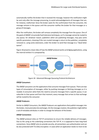
Figure 18 - Advanced Message Queueing Protocol Architecture.............................................. 31
Figure 19 - AMQP Connection with multiple AMQP Channels [67]........................................... 32
Figure 20 - AMQP Direct Exchange ............................................................................................ 33
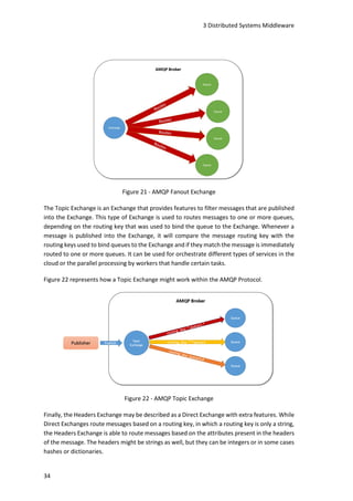
Figure 21 - AMQP Fanout Exchange........................................................................................... 34
Figure 22 - AMQP Topic Exchange ............................................................................................. 34
Figure 23 - XMPP Network Example .......................................................................................... 37
Figure 24 - Data Distribution Service Architecture .................................................................... 44
Figure 25 - ENCOURAGE Architecture........................................................................................ 47
Figure 26 - ENCOURAGE Cell...................................................................................................... 48
Figure 27 - ENCOURAGE MacroCell ........................................................................................... 48
Figure 28 - Routing Structure of ENCOURAGE Middleware....................................................... 53
Figure 29 - Virtual Devices Module Architecture....................................................................... 56
Figure 30 - Database Handler Architecture ............................................................................... 60
Figure 31 - MeterReadings Class Diagram ................................................................................. 62
Figure 32 - EndDeviceControls Class Diagram ........................................................................... 62
Figure 33 - RabbitManager Dynamic Design.............................................................................. 64
Figure 34 - RabbitManager Massively Multi-threaded Design .................................................. 65
Figure 35 - RabbitManager Multiple Channel Design................................................................ 66
Figure 36 - RabbitManager Final Architecture........................................................................... 67
Figure 37 - Interval- 0ms | PrefetchCount - 0 | Delivery Mode - Non Persistent...................... 69
Figure 38 - Interval- 30ms | PrefetchCount - 0 | Delivery Mode - Non Persistent.................... 70
Figure 39 - Interval- 35ms | PrefetchCount - 0 | Delivery Mode - Non Persistent.................... 70
Figure 40 - Interval- 50ms | PrefetchCount - 0 | Delivery Mode - Non Persistent.................... 70](https://image.slidesharecdn.com/92f87b03-0698-478e-aa11-0553917d09f4-161208174943/85/Cesar-Teixeira-Middleware-for-Large-scale-Distributed-Systems-11-320.jpg)
![xii
Figure 41 - Interval- 300ms | PrefetchCount - 0 | Delivery Mode - Non Persistent..................71
Figure 42 - Arrowhead Framework Architecture .......................................................................75
Figure 43 - Virtual Market of Energy [84]...................................................................................78
Figure 44 - Aggregator Class Diagram ........................................................................................80
Figure 45 - Aggregator Sequence Diagram.................................................................................81
Figure 46 - Aggregator Manager Resource Tree ........................................................................82
Figure 47 - FlexOfferManager Class Diagram.............................................................................85
Figure 48 - Flex-offer Manager Resource Tree...........................................................................86
Figure 49 - DER Manager Resource Tree....................................................................................86
Figure 50 - Lego Washing Machine (1).......................................................................................90
Figure 51 - Lego Washing Machine (2).......................................................................................90](https://image.slidesharecdn.com/92f87b03-0698-478e-aa11-0553917d09f4-161208174943/85/Cesar-Teixeira-Middleware-for-Large-scale-Distributed-Systems-12-320.jpg)


![2 State of the Art
8
Middleware brings several advantages to distributed systems architectures, but first it is
important to explain what actually distributed systems are, how they can be characterized, why
they are important and where we can find examples of distributed systems nowadays. This
information is provided in the next subsection of Distributed Systems.
2.1 Distributed Systems
Applications and systems are evolving faster than ever and all kind of devices are in constant
communication, exchanging huge amounts of information. This evolution brings lots of
challenges regarding interoperability, scalability, data storage, computational power (especially
on mobile devices like smartphones, tablets or low power devices) [1], etc.
The term “distributed systems” was originally used to identify computer networks where the
components of the network, usually computers, were distributed geographically in some area
[2]. Distributed systems are systems where several components in a network communicate and
coordinate tasks passing only messages among them to achieve a common goal [1].
According to Tanenbaum, Van Steen, a distributed system can be defined as “a collection of
independent computers that appears to its users as a single coherent system”. This means that
for an end-user, an application or system is located only at one place or is only a single piece of
software, whilst in fact the application or system may be distributed across multiple computers,
physically near or geographically distributed [3].
The main motivation to design and implement distributed systems is the ability to share
resources between computers, systems or even users. A resource can be anything, but what
really matters is that resources are useful things that can be shared between systems in a
network, like printers, shared disks or webpages in case of Internet. The Internet of Things (IoT)
is another concept that has gained lot of importance in the past decade [4].
Internet of Things is one of the recent and most important motivations for the deployment of
distributed systems, mainly due to the capabilities it can provide [4] [5]. The main goal of IoT is
to have all the objects around us connected to the Internet and communicating with each other
without, or with a minimal, human intervention, trying to provide a better world for humanity.
This objects, also known as smart-objects [6] due to its intelligence, should be capable of
acquiring information of what we like or want and act according to that to provide us something
in return [7].
Figure 1 is intended to highlight the most common challenges of distributed systems.](https://image.slidesharecdn.com/92f87b03-0698-478e-aa11-0553917d09f4-161208174943/85/Cesar-Teixeira-Middleware-for-Large-scale-Distributed-Systems-24-320.jpg)
![Middleware for Large-scale Distributed Systems
9
Figure 1 - Distributed Systems Challenges
In Figure 1, one of the challenges of distributed systems is the heterogeneity among computers
and networks, which can be applied to multiple scenarios, such as networks, computers
hardware, operating systems, programming languages or even different implementations by
different developers. This is an issue for the design of distributed systems, which aims to offer
an infrastructure where all the systems may communicate with each other. The term
middleware tries to mask this heterogeneity in distributed systems.
Middleware can be a piece of software that gives developers a high abstraction regarding the
differences between all systems that may interact, from hardware to operating systems,
networks or programming languages. Another approach for this heterogeneity challenge is the
concept of mobile code, where pieces of code are transferred from one computer to another,
for example with virtual machines, to be executed.
Transparency is another challenge when designing distributed systems that aims to give the end
user the perception of a unique system, even if it is composed by several independent
components. The ANSA Reference Manual identifies eight forms of transparency, such as
Access Transparency, Location Transparency, Concurrency Transparency, Replication
Transparency, Failure Transparency, Mobility Transparency, Performance Transparency and
Scaling Transparency [1].
The most important forms of transparency are the Access and Location, where the local or
remote resources can be accessed identically and resources can be accessed without knowing
the exact location of them [1].
The Concurrency refers to the fact that multiple processes may interact at the same time with
shared resources and Replication refers to the existence of multiple instances of resources,
without knowledge of users or developers, to improve the reliability and performance of a
system. Failure Transparency provides the ability to users or other programs to finish](https://image.slidesharecdn.com/92f87b03-0698-478e-aa11-0553917d09f4-161208174943/85/Cesar-Teixeira-Middleware-for-Large-scale-Distributed-Systems-25-320.jpg)
![2 State of the Art
10
completely their tasks even if some components of the whole system is down or broken,
hardware or software [1] [3].
The Mobility Transparency allows the exchange of resources among users of other systems
without interfere with the system or users operations. The Performance Transparency allows
the reconfiguration of the system along its execution if needed. At last, the Scaling Transparency
refers to the ability to expand the system without interfere with the main structure of the
system [1].
The Openness is another challenge of distributed systems and it is determined by the possibility
of extending the main system by adding more services of resources. This implies the distribution
of documentation to developers in order to create new resources and make possible the
integration of new compliant components [1] [3].
The Concurrency in a distributed system means that each resource of that system might be
accessed by several clients at the same time. The distributed system must handle those
concurrent resource accesses, synchronizing them to maintain data consistent [1] [3].
Another challenge in distributed systems is Security. The information that is exchanged and
stored in a distributed system needs to be protected and secured, since it might be extremely
important to users. The security in resources follows three main characteristics: confidentiality,
protecting resources from unauthorized individuals; integrity, protecting against corruption or
its modification; and availability, keeping a resources always available by any means [1] [3].
Scalability is another challenge of distributed systems and also one of the most important ones.
Distributed systems should be capable of expanding in cases it is needed, for example as load
vary. The difficulty of this challenge is the fact that when a system expands, it should not
interfere with the main system. This means, for example, that data should be replicated to
prevent data loss [1].
If more computational processing or more data storage capacity is needed, distributed systems
are perfect to handle this kind of issues. In any system, reliability is also very important and
once again, distributed systems are helpful since redundant components can be added at any
time, for example using virtualization techniques.
The most recent evolutionof the virtualization techniques, which allows the creation of multiple
Virtual Machines instead of having multiple physical machines, brought innovative and easy
ways to greatly facilitate the deployment of distributed systems [8]. This kind of techniques
reduces the time spent of systems administration, increases the uptime and allows to create
multiple Virtual Machines [9] [10] locally.
Finally, the Resilience to Failures is another challenge identified in distributed systems. In
distributed systems, failures of hardware or software components should be detected and
handled whenever possible. In terms of data corruption, checksums are an example of how this](https://image.slidesharecdn.com/92f87b03-0698-478e-aa11-0553917d09f4-161208174943/85/Cesar-Teixeira-Middleware-for-Large-scale-Distributed-Systems-26-320.jpg)
![Middleware for Large-scale Distributed Systems
11
can be detected. In any way, failures should be hidden to the end users, providing some features
to avoid systems to fail as a whole [1].
Distributed systems provide huge savings in terms of cost, since there is no need to have
mainframes to make all the processing. Compared to mainframes, distributed are extremely
powerful, being possible to have an enormous number of computers processing and storing
information at the same time. In this way, we can assume that distributed systems brought an
incredible increase of performance.
There are some applications that are used every day and are naturally distributed, such as the
Web, the email, instant messaging (IM) applications or even social network, like Facebook,
Google+, Twitter, etc. In terms of cons, distributed systems rely on networks. Since network
capacity is limited, this can be a bottleneck in this kind of systems.
A big issue that concerns every system designer or administrator is the security [11]. When
networks were composed by a small number of computers, it was easier to manage and
maintain security policies, however in distributed systems, it isn’t so easy to achieve.
Finally, the software complexity tends to increase as long as the distributed system gets bigger
and there is a need to make every component of the architecture interactive. There are
alternatives, ways of reducing that complexity, for example with the usage of a middleware-
based architecture, exposing the same interface to every application.
There are several examples of distributed systems, such as Enterprise Information Systems, the
Massive Multiplayer Online Games (MMOGs), Code Offloading, Smart Grids and Smart Cities,
Cyber Physical Systems and more recently the Cloud-based systems. Each one of this examples
is described in more detail in a separate section of this chapter.
2.2 Distributed Systems Architectures
Distributed systems can be designed in several ways, originating multiple types of architectures,
depending on the context in which the system will rely on. Distributed systems architectures
might be centralized or decentralized.
In centralized systems, every component of the architecture has knowledge of the state of the
system whilst in a decentralized system, each component works by itself, not knowing (it can
also know, but that is not the strictly needed) the state of other components.
Centralized architectures provide a total aware of the overall system with a unique point of
failure, however in some cases, the non-existence of a single point of failure is an advantage,
for example if in a distributed system on of the components of the architecture fails, it can exist
another similar or equal node that is able to perform the same tasks, resulting in a total
awareness of the failures by the end users of the system [12].](https://image.slidesharecdn.com/92f87b03-0698-478e-aa11-0553917d09f4-161208174943/85/Cesar-Teixeira-Middleware-for-Large-scale-Distributed-Systems-27-320.jpg)
![2 State of the Art
12
Within centralized architectures, relies a common and widely used type of architecture, the
client-server architecture. Client-server architectures consist on having components providing
services, acting as servers, and other components acting as clients that use services provided
by servers [13].
In this kind of architectures, clients and servers may be located in the same machine but they
can be distributed in different machines as well. Usually clients interact with servers through a
request-response model, where a client contacts the server requesting for some information,
and then it waits for an answer from the server. In the end the client receives the answer and
handle it. Figure 2 presents an example of how a client-server architecture looks like.
Figure 2 - Example of a Client-Server Architecture
Applications, which implements client-server architectures, can be structured in different
layers, each one with a specific function. The three-tier architecture, also known as multi-tier
architecture [14] [15], provides three different layers, the user-interface layer, the processing
layer and finally the data layer. Each layer interacts with another layer, in a hierarchical manner.
The user-interface layer provides only the graphical user interface (GUI) to the user, without
having any processing or logic capabilities. The middle-layer, or the processing layer, is
responsible for processing the entire logic of the application that is then sent to the bottom
layer, the data layer, responsible for the data management of the application (for example
through databases, files, etc.).
Figure 3 shows an example of the three-tier architecture.](https://image.slidesharecdn.com/92f87b03-0698-478e-aa11-0553917d09f4-161208174943/85/Cesar-Teixeira-Middleware-for-Large-scale-Distributed-Systems-28-320.jpg)
![Middleware for Large-scale Distributed Systems
13
Figure 3 - Example of Three-tier Architecture
In the cyber physical systems context, this kind of client-server architecture is commonly used
with a two-layered view, consisting in a layer responsible only for the user-interface, since it is
generally smaller devices without processing capabilities, and a procession and data layer,
which resides in the server. This scenario usually results in more loaded network traffic due to
the need of the clients to send the entire raw data to the server for the processing.
Another example of a centralized architecture is the Distributed objects architecture, which
consists in several objects interacting with each other, but opposing to the client-server
architecture, in this case objects are viewed as equal among them. There is no difference
between clients and servers, since every object in the architecture might act as server or client
at the same time.
The opposite of centralized are the decentralized architectures which means that in this kind of
architectures, the components of the architecture are not aware of the state of the other
components. Peer-to-peer [16] or SOA [17] are examples of decentralized architectures.
Peer-to-peer architectures consist in making clients interact directly with other clients without
the need to use a server as a bridge [18]. The peer-to-peer technology is widely used in several
systems like instant messaging, gaming of distributed data management and bit torrent systems
[19].
This kind of architectures are a very good approach for multimedia streaming, giving the fact
that each client may share its bandwidth with other clients, without the need to overload the
streaming servers. Figure 4 presents an example of how a Peer-to-Peer architecture may be
represented.](https://image.slidesharecdn.com/92f87b03-0698-478e-aa11-0553917d09f4-161208174943/85/Cesar-Teixeira-Middleware-for-Large-scale-Distributed-Systems-29-320.jpg)
![2 State of the Art
14
Figure 4 - Peer-to-Peer Architecture
At last, Service-oriented architecture is the point of view of how a distributed system might be
designed. According to Thomas Erl a service-oriented architecture is defined as “architectural
model that aims to enhance the efficiency, agility and productivity of an enterprise by
positioning services as the primary means through which solution logic is represented in
support of the realization of strategic goals associated with service-oriented computing” [17].
This means that the integration with old systems, but with new systems as well, of this type of
architecture will bring many advantages in terms of performance and scalability.
Figure 5 - Service-oriented Architecture meta-model (The Linthicum Group, 2007)
The fundamental unit of SOA is the actual service. A service is defined as independent software
program that has its own capabilities depending on the context it is inserted in, which are
passive of externally invocation by consumers of that service. A service, however, might be
composed by more services, forming a composed service [17]. Figure 6 depicts two different
kinds of services, the normal ones and the composed ones.](https://image.slidesharecdn.com/92f87b03-0698-478e-aa11-0553917d09f4-161208174943/85/Cesar-Teixeira-Middleware-for-Large-scale-Distributed-Systems-30-320.jpg)
![Middleware for Large-scale Distributed Systems
15
Figure 6 - Service representation in SOA
The implementation of service-oriented architectures brings many advantages, such as the
increased federation, the higher interoperability and the openness since the vendor diversity
increases.
2.3 Distributed Systems Applications
In this subsection the examples of distributed systems referred in the Distributed Systems
Architectures subsection are described in more detail. Each one of the examples depicts
different ways where distributed systems can be applied.
2.3.1 Enterprise Information Systems
The evolution of technology during the last decade brought some challenges to how companies
provide their services and manage internal and external information. Information technologies
started to be integrated into each service or process inside a company trying to provide more
agile and unified systems, becoming easier to use or maintain.
In the past, companies had two main concerns in order to compete with other companies, the
quality of the products and the price they provide. Nowadays, companies must be more focused
not only on the quality and price of their products, but also on the flexibility and a quick
response to customer demands [20]. This new approach enhances the competitiveness with
other companies [21].
Companies are now, more than ever interested in introducing information technologies to their
processes, integrating their own internal systems and evolve to a more centralized system
where everything is possible to monitor and manage from a set of integrated dashboards
accessing multiple company processes [21].
Figure 7 depicts an Enterprise Resource Planning system architecture. This kind of systems can
have impact in many sectors of companies. An ERP system would integrate all the independent
department systems of a company (as a distributed system) in order to be manageable and
monitored through a unique and flexible set of dashboards [21].](https://image.slidesharecdn.com/92f87b03-0698-478e-aa11-0553917d09f4-161208174943/85/Cesar-Teixeira-Middleware-for-Large-scale-Distributed-Systems-31-320.jpg)
![2 State of the Art
16
Figure 7 - Enterprise Resource Planning (ERP) System Architecture
An example of an ERP systems is the SAP Enterprise Resource Planning (ERP) [22], developed
by The German company SAP [23], that provides several modules, each module operating in a
specific sector or the company, such as financial management, manufacturing or human
resources.
The SAP ERP claims to be a system that increases the competitiveness with integrated, fast and
flexible business solutions; accelerates time to market innovative, individualized products and
services; simplifies corporate structure, market channel and business scenario management;
improves corporate resource and asset utilization and obviously a greater customer
satisfaction; and is a consolidated foundation for the latest mobile, cloud-based, and in-memory
technologies [22].
NetSuite is a cloud-based ERP system and it is the most deployed ERP system all over the world.
They claim that the NetSuite ERP “delivers the proven, comprehensive financial management
capabilities required to grow a changing, complex business”. NetSuite ERP takes business
beyond traditional accounting software by streamlining operations across your entire
organization and providing you with the real-time visibility you need to make better, faster
decisions [24].
Microsoft Dynamics Great Plains (GP) is another example of an ERP system, which claims to
“help businesses gain greater control over their financials, better manage their inventory and
operations, and make informed decisions that help drive business success. It's quick to
implement and easy to use, with the power to support your growth ambition” [25].
2.3.2 Massive Multiplayer Online Games
Massive Multiplayer Online Games are another example of how distributed systems are
currently used. This kind of distributed systems are designed in a way that can support
thousands of users at the same time, experiencing an almost real interaction with a virtual
world. In most cases, this virtual worlds are shared among all users, and the fast propagation of](https://image.slidesharecdn.com/92f87b03-0698-478e-aa11-0553917d09f4-161208174943/85/Cesar-Teixeira-Middleware-for-Large-scale-Distributed-Systems-32-320.jpg)
![Middleware for Large-scale Distributed Systems
17
actions and events through all users is a challenge to the designers of this kind of distributed
systems.
Some important examples of MMOGs are the Sony’s EverQuest II [26] and the EVE Online [27]
from the Finnish company CCP Games .
Figure 8 - Example of MMOG Architecture
Figure 8 depicts an example of a MMOG architecture with all its components and interactions.
The architectures is composed by a set of distributed servers, each one of them responsible for
a specific task. First a client connects to a Patch Server, which is responsible for the verification
of clients’ game, checking if the game is updated. Then, clients connect to the Login Server,
which is responsible to query the database in order to check if that client is already registered.
After the authentications, a client connect to a Proxy Server that is responsible to forward data
from the client to the Game Servers and backwards, or compressing and decompressing data.
Game Servers are the servers where clients will be playing and interacting, which are in constant
communication with the World Server.
The World Server is the master server in the cluster, which means that the main features of the
game are handled in this server. The existence of several Game Servers provides a high scalable
and performant system, by adding new Game Servers, for example as load increases.
Finally, when something needs to be persisted, a database is used to keep that data stored.
However, databases might be a bottleneck due to excessive accesses or queries, and to avoid it
a Synchronization Server might be used to synchronize the database queries, highly reducing
the load of the system, providing an asynchronous way of communicating with the database,
enabling an in-memory change of users or objects of the game [28].
2.3.3 Smart Grids
An energy grid is defined as network composed by several systems interconnected that has the
capability of deliver electricity from suppliers (power plants) to consumers (houses, buildings,](https://image.slidesharecdn.com/92f87b03-0698-478e-aa11-0553917d09f4-161208174943/85/Cesar-Teixeira-Middleware-for-Large-scale-Distributed-Systems-33-320.jpg)
![2 State of the Art
18
factories, etc.) [29]. Former energy grids have evolved and a new concept has emerged, the
new concept of smart grids. From this first definition, it is implicit the importance of distributed
systems in the designing and deployment of smart grid concept. The NIST Framework identified
75 standards that are useful in the smart grids context, providing a high-level conceptual [30].
Smart grids are the future of electrical grids, evolving from a unidirectional production,
transmission, distribution and consumption pipeline, from production plants (production
domain), to a much more complex system where every actor of the grid can producer or
consume energy (consumption domain) at the same time, store energy or exchange energy
with other actors.
From several architectural solutions that were proposed, where systems seems to be the key
role of the concept, with smart grids the energy grid is able to interact directly with the final
user, having the ability to interact and control appliances, such as washing machines or heat
pumps, in order to provide a more efficient energy consumption [31].
A Smart grid is a very complex network of systems interacting with each other pursuing the
same goal of providing energy efficiency [32]. The adoption of the smart grid concept brings
new challenges, such as the low-level communication technologies [33], issues with the
Distributed Energy Resources [33] or electrical vehicles [34].
Figure 9 - Example of a Smart Grid Use-case [35]
Even with multiple definitions, a smart grid is generally defined as a merge between the
traditional energy distribution network and the capability of having a multi-directional (instead
of the unidirectional in former energy grids) way of communication. Giving the fact that the
communication between entities flows from both sides, the grid will be able to sense, monitor
and exchange information about the energy consumption [36].
Smart grids have a common characteristic that relies on embedded devices, sensors and
actuators that are responsible for managing energy and controlling appliances in users’ houses,
usually through a gateway. This means that gateways are one way to centralize communications
in the smart grid architecture. Basically the goal is to have gateways that are capable of](https://image.slidesharecdn.com/92f87b03-0698-478e-aa11-0553917d09f4-161208174943/85/Cesar-Teixeira-Middleware-for-Large-scale-Distributed-Systems-34-320.jpg)
![Middleware for Large-scale Distributed Systems
19
managing a subset of embedded devices, using adequate protocols, and that are connected to
the internet in order to communicate with the grid services [37].
Lots of efforts have been made to implement the smart grid concept in many Europen
countries, however several issues must be addressed to achieve all the advantages of a smart
grid. These issues are related to the need to change and adapt existing infrastructures to
support the integration of digital systems, support interaction between all the entities that
make part of the grid (e.g. for demand response aplications), the non-existence of a virtual
energy market, etc.
According to a study regarding the Convergence to the European energy policy in European
countries [38], the installation of smart meters in countries, green commitments or distributed
generation of energy are examples of challenges that each country faces that were compared.
This study proved that the north countries of Europe, such as Finland, Norway and Sweden are
making a big effort to design and implement a virtual market of energy capable of managing
the energy exchanges among those countries [38].
In a distributed system like a smart grid, one of the challenges is the heterogeneity among all
the systems that compose the smart grid, such as the protocols used for communication,
exposed interfaces of each system, or even programming languages in which they are
implemented.
To get through this challenge, standards seem to be one of the best ways to share knowledge
among developers, sharing, for example, best practices which leads to an economic efficiency
too [39]. Standards are what makes easier the integration of systems, enhancing the
interoperability of those systems, exposing an “interface-like” equal to all systems that uses it.
According to Dr. W. Charlton Adams, Jr. [40], “In order for the Smart Grid to be successful, there
needs to be a set of well-established standards in place that all industries and organizations
involved can utilize.". Standards are the critical for the evolution of smart grids since it gives the
possibility to ensure the compatibility and interconnection of systems implemented worldwide.
In most distributed systems, even more in complex ones like smart grids, standards are very
important in order to provide interoperability and easier integration of systems. Instead of
modelling systems in a plain formatted way, with standards is possible to define a more
structured and hierarchical system. Also to establish the communication between systems
becomes faster and convenient, since every one speaks a common language. Finally, in terms
of cost, standards tens to reduce the cost of installation, configuration and maintenance of
devices.
Follows a brief description of some of the current standards that can ensure the
implementation and interoperability to smart grids.](https://image.slidesharecdn.com/92f87b03-0698-478e-aa11-0553917d09f4-161208174943/85/Cesar-Teixeira-Middleware-for-Large-scale-Distributed-Systems-35-320.jpg)
![2 State of the Art
20
Common Information Model
Common Information Model [41], or CIM, is an open-standard that aims to provide a unified
and consistent way of how information exchanged between distributed systems is viewed, in
order to any CIM-compliant system be able to retrieve that information [42].
The CIM Standard is composed by the CIM specification [43] and CIM schema [44], where the
specification describes the language, naming, Meta Schema (formal definition of the model,
defining terms used to express the model and their usage and semantics) and mapping
techniques to other management models such as Simple Network Management Protocol
Management Information Bases (SNMP MIBs) and Distributed Management Task Force
Management Information Format (DMTF MIFs).
IEC61850
The Communication networks and systems in substations standard (IEC61850) has been defined
by the International Electrotechnical Commissions’s (IEC) [45] and aims the design of electrical
substation automation systems [46]. Since abstract data models define it, it can be mapped to
a large number of protocols, such as Manufacturing Message Specifications (MMS), Sampled
Measured Values (SMV) and in a near future Web Services.
The core components of the IEC61850 are an object mode that describes the information
available through an abstraction definition of services, data and Common Data Class and
independent of underlying protocols; a specification of the communication among intelligent
electronic devices existent in a substation automation system; and a configuration language
that allows the exchange of configuration information.
The IEC 61850 is divided into ten different standards, from the Basic Principles to Glossary,
General Requirements, System and Project Management, Communication Requirements,
Substation Automation System Configuration, Basic Communication Structure and
Conformance testing.
The advantages of using this standard are that it supports a comprehensive set of substation
functions and it is easy to design, specific, configure, setup and maintain. It also provides a high
performant multi-cast messaging communications and it is extensible and flexible which allows
systems evolution.
2.3.4 Smart Cities
The concept of smart cities does not have yet a clear definition but according to Robert G.
Hollands it could be defined as the “utilization of networked infrastructure to improve
economic and political efficiency and enable social, cultural and urban development” [47]. In
this context, the term infrastructure might be defined as the existent elements in a city, such as
business services, housing, leisure and lifestyle services, and ICTs (mobile and fixed phones,
satellite TVs, computer networks, e-commerce, internet services) [48].](https://image.slidesharecdn.com/92f87b03-0698-478e-aa11-0553917d09f4-161208174943/85/Cesar-Teixeira-Middleware-for-Large-scale-Distributed-Systems-36-320.jpg)
![Middleware for Large-scale Distributed Systems
21
The development and implementation of smart cities bring a large number of challenges to the
traditional way everyone see a city and the infrastructures it holds since an uncountable
number of devices are interconnected and communication with each other to provide valuable
information to achieve efficiency in several elements that compose a city. Smart cities can be
characterized as a huge number of devices and services that are interconnected (distributed
systems), providing easy access to them and bringing efficiency in several aspects.
The Department for Business Innovation & Skill from United Kingdom Government, delivered
in 2013 a background paper where they present some of the challenges that the concept of
smart cities will bring to their cities, which may be generalized to every country in the world
[49].
One of the challenges is the rapid evolution and usage of technology lead to unemployment in
all sectors, mainly in younger people, which means that an economic restructuring is needed to
support this changes. The increasing number of population moving to cities from more rural
zones is also a challenge implying lots of changes in how the housing and the transport sectors
are managed. Due to crisis, city authorities are getting lower budgets that makes harder to
follow the proper response to the new changes [49].
Figure 10 - Smart Cities impact
Figure 10 presents a set of sectors where smart cities have impact.
In terms of environment, smart cities will have impact in areas like the green pollution control
or the climate change adaption, aiming to reduce the energy waste (using smart meters) and
reducing emissions. Smart cities will affect the business industry regarding sustainability,
information communication technologies and a smart economy. The innovation on how people
deal with daily task using new equipment and the appearance of new ways to handle or monitor
health problems in an ageing population [49] is another value that smart cities bring. In the
sector of transports, electric vehicles and the dynamic control of traffic are also examples of](https://image.slidesharecdn.com/92f87b03-0698-478e-aa11-0553917d09f4-161208174943/85/Cesar-Teixeira-Middleware-for-Large-scale-Distributed-Systems-37-320.jpg)
![2 State of the Art
22
how smart cities will help people’s life. Smart cities will also bring new ways to handle the
education and the easier access to government services will help to create a happy and
proactive community.
2.3.5 Cyber Physical Systems
Cyber physical systems have multiple ways to be defined but commonly it is defined as set of
components in a computer, both hardware and software, which work together to achieve and
a common goal [50].
The term microprocessor is usually associated to personal computers, however, even if it is not
totally wrong, microprocessors are used in almost every device or appliance we daily use. Most
recent cars can have more than 50 microprocessors [51], to control and monitor transmissions
through electronically controlled gearboxes, brakes through anti-lock systems, electric
windows, etc.
Microwaves ovens, that we use almost every day, are another example of an appliance that is
controlled by this type of systems and we are normally not aware of it [50]. Embedded systems
are widely used in many other areas, from home automation to control appliances,
entertainment devices like smartphones or tablets, wearables for entertainment or medical
purposes in order to diagnose or monitor some body aspects, such as heartbeat frequency,
levels on diabetics.
Figure 11 presents a set of devices that are examples of cyber physical systems.
Figure 11 - Categories of Cyber Physical Systems [52]
In the context of smart grids and smart cities, cyber physical systems play an important role.
Smart meters, sensors or actuators are examples of this systems which provide relevant
information about the energy consumption (smart meters) helping to bring more efficiency to
energy usage, motion detection, smoke detection, temperature, humidity and pressure in an
area (sensors), or the control of appliances as washing machines, lightning or heaters
(actuators). Sensors and actuators are similar, but sensors can only provide information about](https://image.slidesharecdn.com/92f87b03-0698-478e-aa11-0553917d09f4-161208174943/85/Cesar-Teixeira-Middleware-for-Large-scale-Distributed-Systems-38-320.jpg)
![Middleware for Large-scale Distributed Systems
23
the environment they are integrated whilst actuators beside the capability of gather
information about the environment it is also capable of controlling appliances where they are
integrated.
Once again, cyber physical systems are an example of distributed systems (real-time distributed
systems or multimedia systems) [53], since several microprocessors can be distributed within a
device, belonging to the same system, but providing information and actuating in specific
functions.
2.3.6 Cloud-based Systems
“Cloud” computing became relevant when Google announced that they would work on the
concept. Since then, lots of efforts were made in terms of virtualization, distributed computing,
grid computing, networking and obviously web and software services [54]. The Cloud
computing concept relies in a Service-oriented Architecture [55] providing a large number of
orchestrated functions, through services.
Cloud services utilization is growing in popularity since the advent of the Cloud computing.
Figure 12 depicts the evolution since the appearance of the World Wide Web until the
appearance of the Cloud computing concept.
Figure 12 - Evolution of Systems [56]
In this Cloud distributed systems model, data and computation are no longer mandatory in all
devices, but rather somewhere in a “cloud”, though the existence of virtual computers in data
centers worldwide.](https://image.slidesharecdn.com/92f87b03-0698-478e-aa11-0553917d09f4-161208174943/85/Cesar-Teixeira-Middleware-for-Large-scale-Distributed-Systems-39-320.jpg)
![2 State of the Art
24
This new model changed the way distributed systems were designed, offering not only huge
processing capabilities in third-party virtualized computers, but also in terms of Cloud storage
services, such as Dropbox [57] or Box [58], providing dozens or hundreds of gigabytes of storage
in the Cloud for free.
The large amounts of storage services available in the Cloud is an extremely important
advantage in terms of distributed systems, since it allows tons of information, from documents
to multimedia elements, like videos of photos, to be shared among Cloud systems, making them
accessible from anywhere.](https://image.slidesharecdn.com/92f87b03-0698-478e-aa11-0553917d09f4-161208174943/85/Cesar-Teixeira-Middleware-for-Large-scale-Distributed-Systems-40-320.jpg)
![25
3 Distributed Systems Middleware
Distributed systems brought several issues to the design of system architectures, mainly
regarding network and communication between components of the system. As part of the
distributed systems, middleware is a piece of software which is responsible for enabling the
communication and cooperation between the components of the architecture [32].
This software layer aims to provide an abstract manner for developers to integrate enterprise
systems without having the knowledge of which vendors implemented them, for how long or
the protocols they use to exchange information [59]. The usage of a middleware-based
architecture aims to solve network issues that might occur in distributed systems, aiming to
enhance performance, scalability, reliability, security, mobility, quality of service (QoS) and
multicasting.
In terms of performance, using a middleware it is supposed to reduce the latency and data
transfer rates. Regarding scalability, if the systems demands, it should be possible to add any
kind of nodes to the system, without having problems with integration. In this kind of systems
where thousands of messages may be exchanged between applications, there is a need to make
sure that those messages arrive and in the correct order – reliability – and middleware
technologies aim to increase it.
Security is always a subject of great importance in distributed systems, maintaining the
consistency and privacy of the data exchanged. There are ways to ensure security using
firewalls, encryption, Virtual Private Networks (VPNs) which already provides encryption.
Another issue is the possibility to move applications from one place to another without stopping
the application and middleware technologies due to its capability of replication of nodes, tries
to solve this problem. In large-scale distributed systems, applications have different demands,
which means that must be a way to guarantee that the overall system fits their needs.](https://image.slidesharecdn.com/92f87b03-0698-478e-aa11-0553917d09f4-161208174943/85/Cesar-Teixeira-Middleware-for-Large-scale-Distributed-Systems-41-320.jpg)
![3 Distributed Systems Middleware
26
At last, but not least, multicasting. Multicasting is the ability that a system provides to enable
the communication from one-to-many or many-to-many applications at the same time [60].
There are several middleware solutions for the integration that simplify the integration of larger
distributed systems, such as Remote Procedure Call (RPC) oriented middleware, Transaction-
oriented middleware (TOM), Object-Oriented/Component middleware (OOCM) and finally
Message-Oriented middleware [32].
Figure 13 presents a set of middleware types.
Figure 13 - Middleware Types
A Remote Procedure Call oriented middleware is characterized by a set of functionalities and
infrastructures that enables the invocation, in a synchronous way, of procedures from remote
systems. In cases where this type of middleware is used, most of the times client-server
architectures, any system makes a call to a procedure in another remote system and waits for
the answer (synchronous communication) [32]. It is possible though, to develop a multi-
threaded system to simulate an asynchronous communication, however this kind of systems
tend to make more difficult to systems to scale and usually presents a low-fault tolerance
capability [61].
Figure 14 shows two examples of a RPC oriented middleware architectures.
Figure 14 - Remote Procedure Call Oriented Middleware
In distributed systems where it is needed to provide a reliable transaction of operations, for
example in cases in which databases are a central piece of the architecture, the Transaction-](https://image.slidesharecdn.com/92f87b03-0698-478e-aa11-0553917d09f4-161208174943/85/Cesar-Teixeira-Middleware-for-Large-scale-Distributed-Systems-42-320.jpg)
![Middleware for Large-scale Distributed Systems
27
oriented middleware (TOM) fits perfectly [32]. Comparing to the RPC oriented middleware, the
TOM provides not only synchronous, but also an asynchronous communication between
systems, facilitating the integration of any system with database management systems [32].
However, Transaction-oriented middleware due to excessive control and redundancy of the
data exchange, to ensure safe operations, it has issues regarding scalability both in the volumes
of data exchange and the number of interaction applications.
Figure 15 shows an example of a Transaction-Oriented middleware.
Figure 15 - Transaction-Oriented Middleware
The Object-Oriented or Component middleware is a flexible type of middleware that can be
described as an evolution of the RPC model, extending the RPC features and adding some new
features based on the object-oriented programming paradigm, such as object references,
inheritance or exceptions [32]. It uses a synchronous communication though, and lacks of
performance when used in some cases like event-based system.
Figure 16 depicts an example of an Object-Oriented/Component middleware architecture.
Figure 16 - Object-Oriented/Component Middleware
Finally, a Message-oriented middleware (MOM) is essentially a type of middleware that allows
the exchange of messages between applications in a distributed system [32]. According to
Edward Curry, a MOM can be defined as “any middleware infrastructure that provides
messaging capabilities” [62].
Figure 17 depicts an example of a Message-Oriented Middleware architecture.](https://image.slidesharecdn.com/92f87b03-0698-478e-aa11-0553917d09f4-161208174943/85/Cesar-Teixeira-Middleware-for-Large-scale-Distributed-Systems-43-320.jpg)
![3 Distributed Systems Middleware
28
Figure 17 - Message-Oriented Middleware
In a MOM system, each client is able to send or receive message other clients using one or more
servers that act as communication intermediaries and route message from one client to
another. Generally, a MOM system works like a peer-to-peer relationship between the clients
in a synchronous or asynchronous way. One of the most important characteristics of this type
of middleware is that it provides that in any system, a client may be changed without affecting
other clients/systems, due to its loose coupling among applications [62].
Comparing to the types of middleware describe above, a Message-oriented middleware
provides both synchronous and asynchronous communication mechanisms. Other features like
data transformation of message contents to fit the receiving application, parallel processing of
messages and the support of several levels of priority are also provided by the type of
middleware [32].
To simplify the integration of larger distributed systems, message-oriented middleware, also
known as MOMs, became a central piece of this architectures taking advantage of an
asynchronous way of communication, providing at the same time a reliable, scalable and robust
implementation, making it an excellent approach for several types of systems.
Message-oriented middleware support more than one communication paradigms, as it is
depicted in Figure 13. It supports paradigms such as Message Passing, Message Queuing and
Publish-Subscribe.
The Message Passing paradigm allows the direct interaction between applications through a
communication channel. The setup and configuration of this channel is responsibility of the
MOM, however it does not hides each client identity, since the each client is defined explicitly
[32].
Another paradigm supported by a MOM is Message Queuing. In this case, the communication
is made through the use of message queues. Once again, the MOM is responsible for facilitate
the creation, access and management of queues. Message queues are the entities that are](https://image.slidesharecdn.com/92f87b03-0698-478e-aa11-0553917d09f4-161208174943/85/Cesar-Teixeira-Middleware-for-Large-scale-Distributed-Systems-44-320.jpg)
![Middleware for Large-scale Distributed Systems
29
responsible for receive and dispatch messages to all clients that are subscribe to it. The dispatch
of messages is made in a First in First Out (FIFO) manner [32]. Message loss in the system is
prevented through the use of message storage in queues [62].
At last, Publish-Subscribe is another paradigm supported by a Message-oriented middleware
and it is an extension of the Message Queuing paradigm. In event-based systems, this paradigm
defines that a message is treated as an event that is exchanged between clients, being published
by some clients and received by other clients that are eventually subscribed to that type of
event [32]. It can have multiple configurations, depending on the context where the system is
inserted: topic-oriented; content-oriented; and data-oriented.
If a client wants to receive all messages exchanged, it can subscribe to a topic (message queue)
receiving all messages received in that queue – topic-oriented. If a client wants to receive only
some types of messages, a filtering mechanism can be applied to the topic-oriented
configuration, providing message inspection and delivering of only the messages that match the
type of messages the client needs – content-oriented. Finally, data-oriented interaction is the
configuration where data structures are shared among clients and whenever a structured is
changed, the new structured is sent (published) to all clients subscribed to it [32].
In a Publish-Subscribe paradigm, a client that publishes messages (publisher) is not aware of
the clients that will receive messages (consumers) through subscriptions. In a system using a
Publish-Subscribe paradigm within a Message-oriented middleware is possible to achieve a high
decoupled architecture since the clients do not need to know where and who are the other
clients It interacts with (space decoupling), if clients are available or receive messages (time
decoupling) and in terms of synchronization, it allows that subscribers might be notified when
message are ready (synchronization decoupling) [32].
There are several protocols that may be used to implement Message-oriented middleware,
however only the Advanced Message Queuing Protocol (AMQP) and the Extensible Messaging
and Presence Protocol (XMPP) are described in detail, due to this thesis context. A brief
description of the Data Distribution Service is also given for context purposes.
Other protocols however, such as the proprietary IBM protocol for the WebSphere MQ (IBM)
[63], the Simple (or Streaming) Text Oriented Messaging Protocol (STOMP) [64] or the Message
Queue Telemetry Transport (MQTT) even if this is an example of a machine-to-machine (M2M)
protocol [65], could also be described in this section.
3.1 Advanced Message Queueing Protocol (AMQP)
The Advanced Message Queueing Protocol (AMQP) is an open standard application layer, which
allows messages exchange between applications or organizations. This means that AMQP is a
protocol for message-oriented middleware (MOM).](https://image.slidesharecdn.com/92f87b03-0698-478e-aa11-0553917d09f4-161208174943/85/Cesar-Teixeira-Middleware-for-Large-scale-Distributed-Systems-45-320.jpg)
![3 Distributed Systems Middleware
30
This section was based in the documentation of the AMQP protocol specification provided in
RabbitMQ official website [66], the guide provided by Michael Klishin and Chris Duncan [67]
and the Alvaro Videla and Jason J.W. Williams book entitled “RabbitMQ In Action – Distributed
Message for Everyone” [68].
Since the 1970s, there was an effort to provide solutions to solve the integration of
incompatible systems. Messaging solutions like the IBM WebSphere were extremely expensive
and for that reason it was not the perfect solution. Furthermore, vendors started to create their
own protocols, which resulted making even more difficult to integrate those systems.
Taking these issues into account, AMQP was designed to be an open standard for messaging
middleware and to enable the interoperability among several technologies and platforms.
The most important units of this protocol are the message brokers. Message brokers act as
bridge between two applications, receiving messages from producers (applications that send
messages to the broker) and routing those received messages to the correct consumers (or
applications that receive and handle publishers’ messages).
The AMQP protocol was used to act as the message bus to coordinate and enable the
communication between all the components of the ENCOURAGE Project architecture. The
advantages that this protocol provides are explained in more detail in Section 4 Design and
Implementation of Components on the ENCOURAGE Architecture.
The AMQP protocol consists of several entities, such as producers, consumers, exchanges,
bindings and queues. Each entity of the architecture plays a different role and when acting
together as one, enables the communication and cooperation between two or more
applications. Producers are applications that are compliant with the protocol, and that publish
messages into the broker. Messages are then published to an exchange in the broker.
The exchanges are responsible for the delivery or routing of copies of the messages to queues,
received from the publishers. The routing of messages from the exchanges to queues follows
some pre-defined rules, called bindings. A binding is the rule that defines the connection of a
queue with a specific exchange. At last, queues are the storage elements of the architecture,
with the capability of storing up to millions of messages at the same time.
Messages may carry several types of attributes as metadata in which some of the attributes can
be used by the broker for routing purposes, however the content of the message is completely
ignored by the broker and can only be used by applications that received the message. For
instance, a message may be defined as persistent or not, which means that if the message is
persistent, and is published into a persistent exchange and is routed to a persistent queue, the
message will be store in disk, otherwise the message will be only in memory and will not be
recovered if the message broker fails.
To ensure that messages are exchanged even if the network where the broker relies fails, AMQP
provides message acknowledgements techniques. When a consumer receives a message, it](https://image.slidesharecdn.com/92f87b03-0698-478e-aa11-0553917d09f4-161208174943/85/Cesar-Teixeira-Middleware-for-Large-scale-Distributed-Systems-46-320.jpg)
![3 Distributed Systems Middleware
32
connected, it should disconnect gracefully, avoiding the abruptly interruption of the TCP
connection.
AMQP Channels
AMQP channels function in the protocol may be defined as the unit that carries message from
and to clients to the broker. There are cases when applications need more than one connection
with the broker and to avoid having many connections kept alive at the same time, AMQP
channels are as “lightweight connections that share a single TCP connection”, meaning that an
AMQP connection might be composed by several AMQP channels at the same time. Doing that,
only one connection needs to be kept alive whilst each channel is able to share that connection
and perform different tasks at the same time. Each channels is set an identifier that can be used
by applications to keep track of what is happening on a specific channel or what callbacks to
invoke.
Figure 19 graphically represents how an AMQP Connection can be, embracing multiple AMQP
Channels at a time.
Figure 19 - AMQP Connection with multiple AMQP Channels [68]
AMQP Virtual Hosts (vHosts)
The concept of virtualization is also present and is provided by the AMQP protocol. To enable
the separation of subsystems, AMQP provides a feature named virtual hosts. This features
allows the creation of multiple subsystems embracing different groups of users, different
exchanges and different queues. To be more precise, creating multiple subsystems means that
a broker can be composed by several (sub)brokers.
AMQP Exchanges and Exchanges Types
In the AMQP protocol, several Exchanges are defined to accomplish multiple purposes.
Exchanges are the entities to where the messages are published by clients (publishers). Once
messages are published into Exchanges, they are routed to zero or more queues depending on
the type of Exchange or rules applied when a queue is bound to an Exchange. There some
broker exclusive Exchanges that are identified by a prefix in the name of the Exchange, as
“amq.”. The types of exchanges are: Default Exchange; Direct Exchange; Fanout Exchange; Topic
Exchange; and Headers Exchange.](https://image.slidesharecdn.com/92f87b03-0698-478e-aa11-0553917d09f4-161208174943/85/Cesar-Teixeira-Middleware-for-Large-scale-Distributed-Systems-48-320.jpg)

![3 Distributed Systems Middleware
36
AMQP Broker Implementations
The AMQP protocol is fully implemented by the known broker RabbitMQ. Another broker that
implements the protocol is the Qpid Apache Project which aims to provide features like multi-
platform support, message queuing, fast routing and distribution of messages, clustering and
federation. Although Qpid seems to be quite a good choice, only RabbitMQ is approached since
it was the broker used in the ENCOURAGE Project, described in detail in Section 3.
RabbitMQ Broker
The RabbitMQ is a message broker software that aims to provide robust messaging for
applications and is was developed to be easy to use and fit the purpose of being could scale and
multi-platform. It is an open source software under the Mozilla Public License. RabbitMQ is
written in Erlang which “is a programming language used to build massively scalable soft real-
time systems with requirements on high availability. Some of its uses are in telecoms, banking,
e-commerce, computer telephony and instant messaging. Erlang's runtime system has built-in
support for concurrency, distribution and fault tolerance” [69].
The RabbitMQ broker is the leading implementation of the AMQP protocol, however using
some adapters it supports several other protocols, such as XMPP, SMTP, STOMP or HTTP. It is
also important to note that RabbitMQ is widely supported by a fully active community that
helps to improve and evolve the broker.
3.2 Extensible Messaging Presence Protocol (XMPP)
The Extensible Messaging and Presence Protocol (XMPP) [70] is a protocol for near-real-time
messaging, presence, and request-response services [71] that was specified by the Internet
Engineering Task Force (IEFT) [72]. Originally it was developed in the Jabber open source
community. The XMPP uses the Extensible Markup Language (XML) as the base format for the
message exchange. Essentially, XMPP is a protocol that aims to provide an infrastructure to
allow the exchange of small pieces of XML among entities in close real-time [73].
This section was mostly based in the documentation of the XMPP protocol specification [71],
and two books “XMPP: The Definitive Guide – Building RealTime Applications with Jabber
Technologies” [73] and “Professional XMPP Programming with JavaScript and jQuery” [74].
Due to XMPP provided features, it has been used to build large-scale distributed systems,
Internet gaming platforms (i.e. MMOGs), search engines and video or audio conferences. The
huge usage of XMPP in a large number of applications that are created or being created
demonstrates how flexible, versatile and powerful this protocol can be [74].
The XMPP protocol is for Message-oriented middleware systems, like the AMQP, and is
categorized as a message passing paradigm, since the identity of clients are always known by
other clients. In fact, even if XMPP is used for peer-to-peer, or client-server architectures, it can](https://image.slidesharecdn.com/92f87b03-0698-478e-aa11-0553917d09f4-161208174943/85/Cesar-Teixeira-Middleware-for-Large-scale-Distributed-Systems-52-320.jpg)
![Middleware for Large-scale Distributed Systems
37
be extended with new features through the definition of XMPP Extensions (XEPs), which are
needed to enable XMPP to be used in very large number of different scenarios, such as multi-
user chat rooms (XEP-0045 [75]) or the publish-subscribe (XEP-0060 [76]) paradigm.
Several XEPs were defined and can be used to extend new features to the XMPP protocol, for
example to used HTTP over XMPP, XMPP over Bosh, Service Discovery and a set of extensions
to support Internet of Things (IoT) scenarios [77].
The XMPP is the protocol used in the Arrowhead Project that will be discussed in detail in
Section 5 Design and Implementation of Components of the Arrowhead Project, to provide an
infrastructure that is flexible, highly scalable, robust and capable of handling a multicasting
environment, where multiple clients are able to communicate with multiple clients at the same
time. In the case of the Arrowhead Project, a specific XEP (XEP-0332: HTTP over XMPP transport
[78]) was implemented to support an HTTP over XMPP [78] communication, providing a similar
Representational State Transfer (REST) communication between clients, over the XMPP
protocol.
The XMPP protocol usually is used for scenarios of decentralized client-server architectures
[73], such as the World Wide Web or email services, however it can be used for peer-to-peer
communication between two servers or two clients. The usage of XML on exchanged messages
in XMPP derives from the large knowledge that developers have in this message format and the
interoperability that it allows since most applications use XML as the base format [74]. Each
client in uniquely identified by a Jabber Identification (JID) [32].
The communication in an XMPP-based architecture is usually composed by clients and servers
and is made possible through the use of streams. In a normal communication, between two
clients, there are two streams, one for each direction of the communication. Messages are then
passed through steams, the XMPP Stanzas that carry the content of the message from one client
to another or to a server [32] [74].
Figure 23 - XMPP Network Example
Figure 23 shows an example of how a communication is established between clients and servers
in the XMPP Protocol. In this figure each client is connected to a server that is consequently
connected with other servers.](https://image.slidesharecdn.com/92f87b03-0698-478e-aa11-0553917d09f4-161208174943/85/Cesar-Teixeira-Middleware-for-Large-scale-Distributed-Systems-53-320.jpg)
![3 Distributed Systems Middleware
38
When one client intents to communicate with another client, first it sends a message to the
server it is connected to. The server will then take care of the message routing to the correct
client. To ensure security, a server after receiving a message from one client, finds the correct
server where the other client that will receive the message, is connected. Once it finds the
server, the server will send the message to the correct server, which will then forward the
message to the final client.
Given the fact that each server communicates directly to the correct server where the client
which will receive the message, it ensure security in communications since it avoids, for
example, spamming that might occur if the message was forward by other intermediary servers
[74].
The XMPP protocol also provides security and authentication mechanisms, using the encryption
of messages through the usage of the Transport Layer Security (TLS) and the Simple
Authentication and Security Layer (SASL), respectively [74].
The XMPP network
The XMPP network can be described as the combination of different actors, namely servers,
clients, components and server plugins. Each one of this actors may be created and modified
by developers [74].
Servers
Servers are the entities present in an XMPP network that are responsible for routing stanzas
from one client to another, not only when clients are connected to the same server, but also
when clients are connected to servers distributed [73] [74].
A group of servers that communicate with each other, form an XMPP network, whilst public
XMPP servers that are interconnected form a federated XMPP network. There are several public
XMPP servers available on the Internet, in which nay client can connect [73] [74].
The XMPP servers are intended to allow clients to connect to them, although it is possible for a
developer to implement some applications or services that use the server-to-server type of
communication in order to provide a more improved efficiency in communications, reducing
the routing overhead on the server [73] [74].
There are several implementations, or servers, of the XMPP protocol, such as the eJabberd
server, the Openfire server or Tigase. This three examples of server implementations are open
source and widely used over the Internet, providing most of the XMPP features. They can be
installed and executed in almost every platform, from Windows to Linux or even Mac OSX [74].
The eJabberd and Openfire servers will be briefly described in more detail further in this section.
Clients](https://image.slidesharecdn.com/92f87b03-0698-478e-aa11-0553917d09f4-161208174943/85/Cesar-Teixeira-Middleware-for-Large-scale-Distributed-Systems-54-320.jpg)
![Middleware for Large-scale Distributed Systems
39
Clients in an XMPP network are entities that can connect to a server through the usage of the
client-to-server protocol. This clients are usually applications, such as instant messaging, or in
some cases automated applications, also known as bots [74]. This client applications usually
connect and authenticate to servers anywhere that are responsible for handling client sessions
or the roster (entity in the server that holds information of who is available in a friends list, in
cases of instant messaging systems).
Components
The XMPP components are entities that can be implemented by developers in order to add
some other features to servers. Components also connect to XMPP servers, but it does not need
the full SASL authentication mechanism, using most of the times a simple password to
authenticate to servers.
Components communication with servers through the component protocol defined in the XEP-
0114: Jabber Component Protocol [79]. This entities have their own unique identification within
the server and are viewed externally as sub-servers.
The Components can also be configured and implemented to route stanzas in the server,
allowing messaging transformation before it is delivered to the client destination.
Plugins
The XMPP servers can be extended not only by Components, but also by other entities, the
Plugins. However, while Components are external applications that can speak the same
protocol of the servers, Plugins are usually written in the same programming language as the
server and since they run inside server processes, they can modify the behavior or the server
as well [73].
Since Plugins do not need to communication through any network socket, they can result, when
needed, in high performant solutions.
The XMPP Addressing
Since the communication between XMPP clients and servers happens over a network, each
client needs a unique identifier that can be used to locate the client or to forward a stanza to
it. This unique identifier is called a JabberID, or only JID [73].
Usually the JID is composed by a domain for servers, and a pair of user and domain for clients.
To avoid complex identifiers, XMPP relies on the Domain Name System (DNS) and it provides
an easy way to identify any system through its JID. Follows an example of how a JID is composed:
(1) For servers: example.org
(2) For clients: user@example.org](https://image.slidesharecdn.com/92f87b03-0698-478e-aa11-0553917d09f4-161208174943/85/Cesar-Teixeira-Middleware-for-Large-scale-Distributed-Systems-55-320.jpg)
![3 Distributed Systems Middleware
40
In the client example, it represents a user that is registered in the server “example.org”.
The XMPP protocol provides another interesting feature in terms of addressing, the resources
[73] [74]. When a client connects to an XMPP server, it can provide a resource or the server will
automatically provide a random one based on that particular connection. This resource can be
a normal string and it is attached to the end of the JID and it could be something like the
following example:
(1) Client connected in his laptop: user@example.org/laptop
(2) Client connected in his smartphone: user@example.org/smartphone
This kind of configuration allows the applications to route stanzas to different devices that are
connected simultaneously. With resources, connections might represent different devices in
different locations, which means that users can be categorized by capabilities, presence. A great
example of how resources can be useful is when an application receives notifications, but on
laptops does not, this means that the stanzas regarding notifications were only routed to the
connections that represent mobile devices.
The XMPP Stanzas
The XMPP Stanzas, or the communication primitives of XMPP [73], are part of the core of the
XMPP protocol, and can be of several types: Message Stanzas, Presence Stanzas and Info/Query
(IQ) Stanzas [74]. Each XMPP Stanza is used depending on the context of the application or
scenario.
The three types of stanzas share a set of attributes that have the same meaning when used in
all of them: the “id” attribute to identify the stanza for distinguish messages; the “from”
attribute defines the address of the client which sent a stanza; the “to” attribute defines that
address of the client destination, to where the message should be forward; and the “type”
attribute defines if it is a message, presence or IQ stanza [74].
Message Stanzas
Message Stanzas are used for the normal communication between two entities [74]. This type
of stanzas are of a “fire-and-forget” type, which means that when an entity send a message to
another, it does not receive any information to acknowledge if the message was received or not
[73] [74].
Within Message Stanzas, the message can be defined as a “normal” message (by default), when
a single message expecting or not acknowledge is sent, as a “chat” message, when the message
is exchange for example in an instant messaging chat between two entities, as a “groupchat” if
the message is exchanged within the context of a multi-user chat room, as a “headline” message
to send alerts or notifications and does not expect a reply of any kind, and finally as an “error”
message, if any error occurs after sending a message [73].](https://image.slidesharecdn.com/92f87b03-0698-478e-aa11-0553917d09f4-161208174943/85/Cesar-Teixeira-Middleware-for-Large-scale-Distributed-Systems-56-320.jpg)
![Middleware for Large-scale Distributed Systems
41
The content of a Message Stanza is inside two optional XML elements, the body and the thread
elements. The body element is used to carry the actual message content that may be human-
readable, whilst the thread might be used to correlate messages like emails, being each
different thread within a unique conversation [74]. Follows an example of how an XMPP
message can be.
<message from=’cesar@isep.ipp.pt/office’
to=’rui@homenetwork.pt’
type=’chat’>
<body>Hi there, how are you?!</body>
<thread>4fd61b376fbc4950b9433f031a5595ab</thread>
</message>
Presence Stanzas
The Presence Stanzas are the type of messages that allows the XMPP protocol to provide
availability features to applications. Basically this type of messages is used to notify or inform
other entities that it is available/online or not/offline. In some cases users can even define
custom messages, informing other entities that is, for example away or listen to music [74].
Presence Stanzas can be of different types like Message Stanzas: Normal Presence Stanzas,
Extending Presence stanzas, Presence Subscriptions or Directed Presence. Providing different
types of Presence Stanzas, the XMPP protocol presents itself as a high flexible technology for
integrating different kinds of applications [73] [74].
In Normal Presence Stanzas a user can inform the server that it is available or not. It is possible
also to send some extra elements in the presence message, informing if it is available but is not
supposed to be disturbed and a status message to be displayed, if wanted, in the client’s
destination [74].
The Extending Presence Stanzas are used to add some other extra information to the Normal
Presence Stanzas. With this type of Stanzas additional information might be sent, for example
to inform what music the client is listening for, and it can be used to display that information to
other clients in chats or other applications [74].
Another type of Presence Stanzas are the Subscription Presence Stanzas. This type of Stanzas
allows several configurations regarding availability of entities in the XMPP server. In cases
where Presence Subscription is used, the server broadcasts the presence information of all
contacts that have a subscription to a specific user. It is important to refer that those
subscriptions and unidirectional, which means that if a user subscribes to another users’
presence, only the user that requested the subscription will receive information about the
presence of the other user. To establish a bidirectional subscription, each user should request
the presence subscription to the other client [73] [74].
Follows some examples of Presence Stanzas. The first example shows how a user requests the
presence subscription to another user, and the second example shows the message received
when a subscription was accepted and established. The third example shows how a user can](https://image.slidesharecdn.com/92f87b03-0698-478e-aa11-0553917d09f4-161208174943/85/Cesar-Teixeira-Middleware-for-Large-scale-Distributed-Systems-57-320.jpg)
![3 Distributed Systems Middleware
42
notify the server that he is available from that moment and the fourth example shows how the
user performs the opposite action, informing the server that he is not available anymore. The
last example shows how a user informs the server that he is away and the reason for being away
is that he is taking a bath [73] [74].
<presence from=’cesar@isep.ipp.pt/office’
to=’rui@homenetwork.pt’
type=’subscribe’/>
<presence from=’rui@homenetwork.pt/home’
to=’cesar@isep.ipp.pt/office’
type=’subscribed’/>
<presence/>
<presence type=’unavailable’/>
<presence>
<show>away</show>
<status>Taking bath</status>
</presence>
At last, there are the Directed Presence Stanzas. In this kind of Stanzas, are like normal Presence
Stanzas but they are not sent to the server, they are sent directly to another user or entity
instead. This type of Presence Stanzas might be useful to notify other entities when users or
applications forget to notify explicitly other entities that they are no longer available.
Info/Query (IQ) Stanzas
Finally, the XMPP protocol provides the Info/Query or only IQ Stanzas. This type of Stanzas is
used to provide an infrastructure for a request-response type of communication, similar to the
HTTP methods GET, POST and PUT [74]. IQ Stanzas unlike Message Stanzas can contain only one
payload [74].
The IQ Stanzas, like the other Stanzas may have different types: “get”, “set”, “result” or “error”.
An IQ Stanza of type “get” is used to request some information, and the “set” type is used to
request or provide some information [74]. The “result” and “error” types are responses to the
“get” and “set” types. Whenever an IQ Stanza of type “get” or “set” is sent, it must be
responded with another IQ Stanza of type “result” or “error” depending on the result of the
request [73] [74].
Follows an example of how an IQ Stanza may be created and used by a user to get the list of
contacts it has on his roster, sending an IQ Stanza of type “get” to the server. Then the server
replies with the list of contacts in the roster.
<iq from="cesar@isep.ipp.pt/office"
id="rr82a1z7"
to="cesar@isep.ipp.pt"
type="get">
<query xmlns="jabber:iq:roster"/>
</iq>](https://image.slidesharecdn.com/92f87b03-0698-478e-aa11-0553917d09f4-161208174943/85/Cesar-Teixeira-Middleware-for-Large-scale-Distributed-Systems-58-320.jpg)
![Middleware for Large-scale Distributed Systems
43
<iq from="cesar@isep.ipp.pt"
id="rr82a1z7"
to="cesar@isep.ipp.pt/office"
type="result">
<query xmlns="jabber:iq:roster">
<item jid="girlfriend@girlfriendhouse.pt"/>
<item jid="father@jobnetwork.pt"/>
<item jid="mother@homenetwork.pt"/>
<item jid="friend@friendnetwork.pt"/>
</query>
</iq>
XMPP Broker Implementations
ejabberd
Ejabberd is an open source Jabber/XMPP server and it is the most used implementation of the
XMPP protocol [80] under the GNU General Public License (GPLv2). It is written in the Erlang
[69] language and it claims to be a stable, massively scalable and infinitely extensible server for
the XMPP protocol that can be used for several different scenarios, such as mobile messaging,
social networks, massively multiplayer online gaming, among many others [80].
The ejabberd server if a modern, fault-tolerance server, manageable, highly versatile and very
modular, providing almost every extension of the XMPP protocol. Ejabberd was made to be
compliant which means that it aims to be interoperable. In terms of security, the ejabberd
server provides several solutions, mainly using TLS encryption of messages and SASL for
authentication of clients [80].
Openfire
The Openfire [81] is also an open source XMPP server written in Java under the license of the
Open Source Apache License. Openfire is an instant messaging server, easy to install, setup and
use. Like ejabberd, the Openfire server provides a rock solid solution, claiming to be highly
secure and with a high performance.
3.3 Data Distribution Service (DDS)
The Data Distribution System for Real-Time Systems (DDS) [82] is a standard that was defined
by the Object Management Group (OMG) organization and claims to be a high performance
middleware for predictable distribution of data between applications [32]. This standard is
mainly used to implement the Publish-Subscribe model for communications in real-time and
embedded systems and provides a set of QoS policies.](https://image.slidesharecdn.com/92f87b03-0698-478e-aa11-0553917d09f4-161208174943/85/Cesar-Teixeira-Middleware-for-Large-scale-Distributed-Systems-59-320.jpg)
![3 Distributed Systems Middleware
44
The DDS is a data-oriented middleware based on the Data Centric Publish-Subscribe (DCPS) [32]
model where it implements a distributed peer-to-peer architecture providing a reliable and
efficient communication among applications [83]. DDS provides high interoperability among
heterogeneous systems through the existence of a Global Data Space (GDS), where multiple
applications publish (publishers) messages into the GDS, and other applications (subscribers)
are able to access the same GDS and subscribe to the information they are interested [83]. Every
time a publisher changes data in the DDS, the DDS is responsible for propagating that changed
data to all subscribers [32].
In DDS, the data available in the GDS follows a data model based on structures. Each structure
is identified by a topic that uniquely identify the structure (when a client needs to change some
data, it uses the topic to deliver the data to the correct DDS server) and a type that provides
structural information that is used by the middleware to perform actions on that data (used by
a client to perform a preliminary check on the data) [32]. A set of QoS policies is provided by
DDS aiming the guarantee of data delivery, real-time systems performance, bandwidth
reservation, redundancy and data persistence.
Figure 24 presents how DDS architecture is defined and works.
Figure 24 - Data Distribution Service Architecture
The DDS is characterized by providing an overall decoupled data-centric publish-subscribe
paradigm. A high decoupled architecture between publishers and subscribers is provided in
space since both may be located anywhere. Neither publishers nor subscribers are obligated to
be available at any time, so DDS provides is high decoupled architecture in time. Publishers and
subscribers may be implemented in different languages and in multiple operating systems or
deployed in different hardware since DDS also provides a high-decoupled architecture in terms
of platform [83].](https://image.slidesharecdn.com/92f87b03-0698-478e-aa11-0553917d09f4-161208174943/85/Cesar-Teixeira-Middleware-for-Large-scale-Distributed-Systems-60-320.jpg)
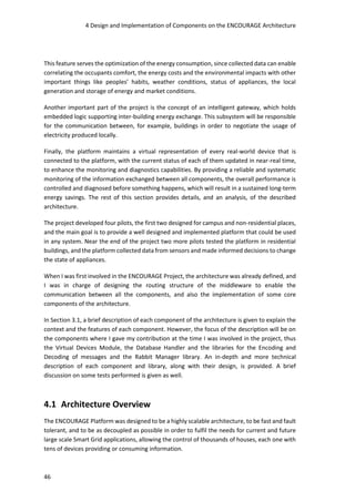
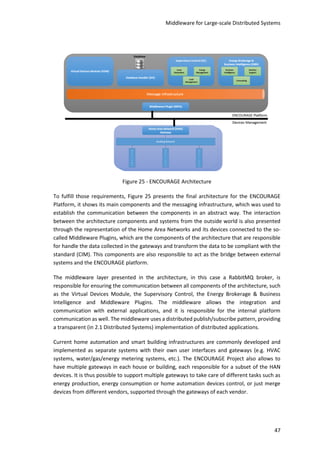
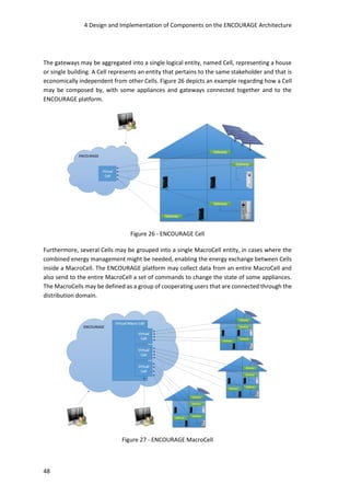
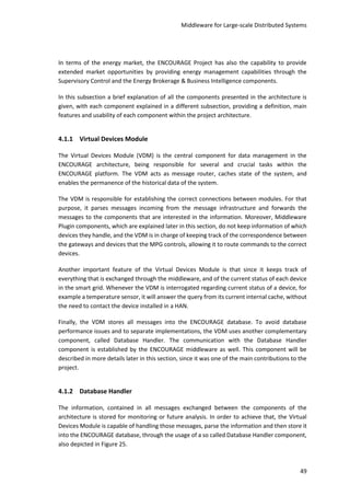
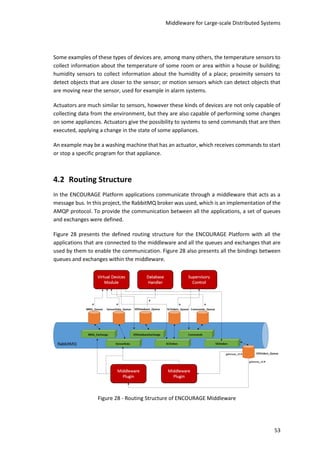
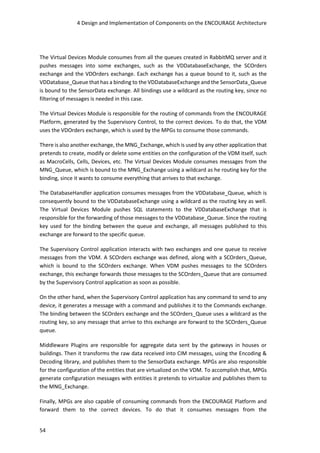
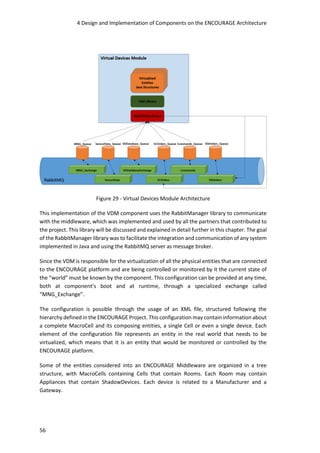
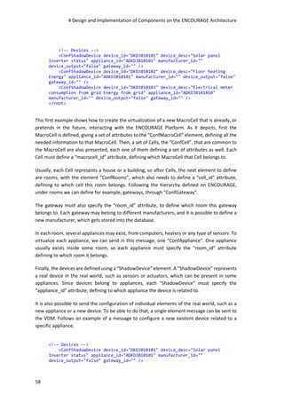
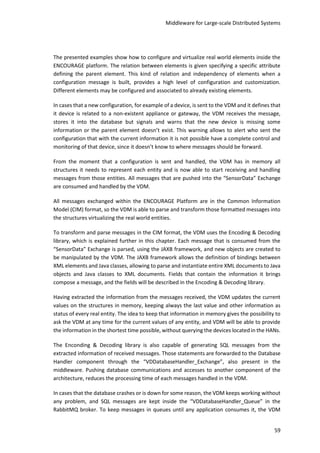
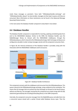
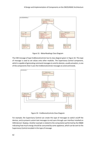
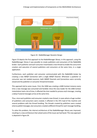
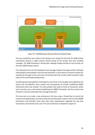
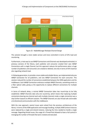
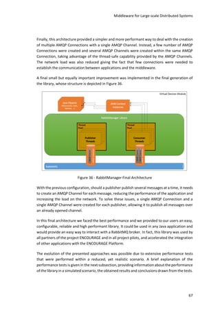
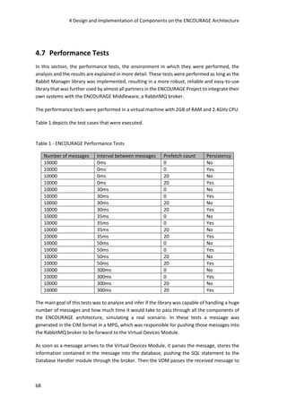
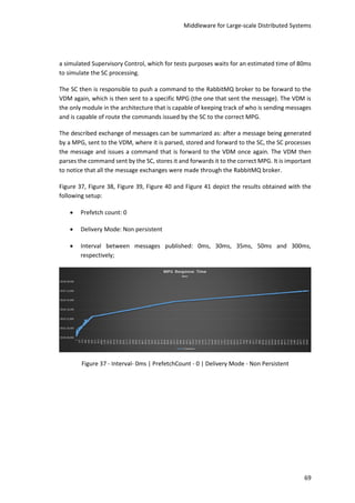
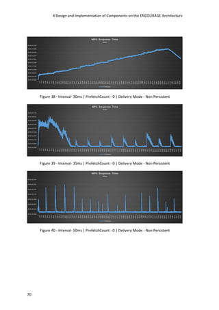
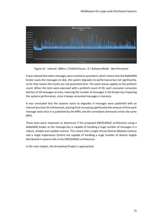
![73
5 Design and Implementation of
Components of the Arrowhead Project
The Arrowhead Project aims to develop a way to facilitate the cooperation between embedded
systems, a highly scalable architecture, and aims to promote high levels of interoperability
among different systems. With these objectives in mind, it present both similarities and
differences to the ENCOURAGE Project. While the ENCOURAGE Project aims to enable one
architecture where several systems communicate through a message bus, the Arrowhead
Project aims to develop a service-oriented framework enabling multiple architectures and
supporting several common functionalities such as to enable the registry and lookup of
systems/services, the authorization, the authentication and even the orchestration of
systems/services.
This section aims to provide an architectural design, implementation and interfaces between
components of the ARROWHEAD Pilot for the Virtual Market of Energy – Generation 1. The
main goal of the pilot is to demonstrate the flex-offer [84] concept, which has the goal of
balancing energy demand and supply, through for example, the synchronization of
consumption with production of energy. The balancing is achieved through shifting
consumption loads to periods of the when energy is cheaper.
The flex-offer approach aims to reduce the energy costs of industrial or domestic installations,
and it helps flattening out energy consumption, refraining, or at least minimizing, the usage and
the negative impact of the peaking power plants. Several entities communicate through a so-
called Virtual Market of Energy, which allows the scheduling of energy consumption or
production. The flex-offers represent the flexibilities and schedules of energy of systems
involved through formal data structures.
The flex-offer approach involves energy consumers, aggregators, and a so-called flexibility
market. Sensors collect energy consumption data from Distributed Energy Resource (DERs).](https://image.slidesharecdn.com/92f87b03-0698-478e-aa11-0553917d09f4-161208174943/85/Cesar-Teixeira-Middleware-for-Large-scale-Distributed-Systems-89-320.jpg)
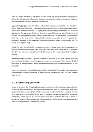
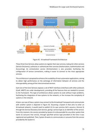
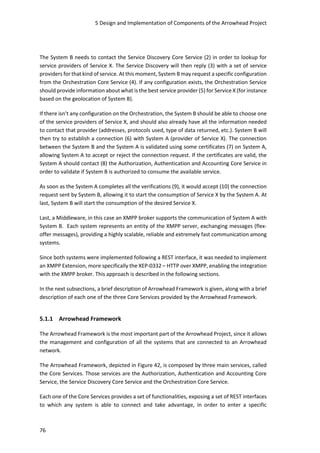
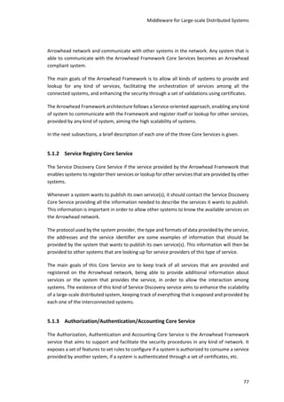
![5 Design and Implementation of Components of the Arrowhead Project
78
The authorization part of the Core Service may be used by a system to verify if some other
system that wants to consume its own service is allowed or not. Then, if it is allowed, the
authentication of the system that wants to consume the service may be verified through a set
of certificates and key stores.
5.1.4 Orchestration Core Service
The Orchestration Core Service is the Arrowhead Framework service that is responsible for the
creation and management of rules that define and control the way how systems interact with
other systems in the network.
Basically, in the Orchestration Core Service it is possible to define rules specifying, for instance,
the best service provider for a certain service consumer. This kind of rules may be defined based
of the geo location of both service provider and consumer, network traffic load, current
condition of the service provider (if it supports more connections from service consumers, etc.),
among other features.
The usage of this Core Service allows the orchestration of service providers and consumers,
facilitating the management and control among all the systems in terms of performance and
scalability of the whole network.
5.1.5 Virtual Market of Energy
For managing flex-offers, it was proposed the usage of a general Virtual Market of Energy
system, which is depicted in Figure 43, by providing a set of Service Oriented Architecture (SOA)
interfaces, responsible for interconnecting several (existing and new) European Electricity
Market Actors [84].
Figure 43 - Virtual Market of Energy [84]](https://image.slidesharecdn.com/92f87b03-0698-478e-aa11-0553917d09f4-161208174943/85/Cesar-Teixeira-Middleware-for-Large-scale-Distributed-Systems-94-320.jpg)
![Middleware for Large-scale Distributed Systems
79
The Prosumers or the Distributed Energy Resources (DERs) can both consume and produce
electricity. Examples of Prosumers are residential houses, commercial buildings,
manufacturing, and process industries. These generate flex-offers and consume schedules [84].
The Aggregators are specialized entities capable of aggregating several (micro) flex-offers from
Prosumers into larger (macro) flex-offers. It is also capable of disaggregating (macro) flex-offer
schedules, e.g., received from the Electricity Market. An aggregator might be an integrated part
of a Balance Responsible Party (BRP) [84].
5.2 Aggregator
The Aggregator component is entrusted for acting as a bridge between the FlexOfferAgent and
the Virtual Market of Energy. This section describes the interfaces and functionality of the
Aggregator component.
This component is capable of executing the following actions:
Receive (micro) flex-offer requests, sent by a FlexOfferAgent;
Accept or reject flex-offers;
Aggregate (micro) flex-offers into (macro) flex-offers;
Disaggregate macro flex-offer schedules into micro flex-offer schedules;
Send assigned (micro) flex-offer schedules to a FlexOfferAgent;
Send flex-offers to and receive assigned flex-offer schedules from the Virtual Market of
Energy (to be implemented in Generation 2);
Request the power consumption and the state of a flex-offer (to be implemented in
Generation 2).
Figure 44 presents a class diagram for the Aggregator component, containing all its classes.](https://image.slidesharecdn.com/92f87b03-0698-478e-aa11-0553917d09f4-161208174943/85/Cesar-Teixeira-Middleware-for-Large-scale-Distributed-Systems-95-320.jpg)
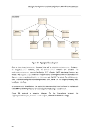
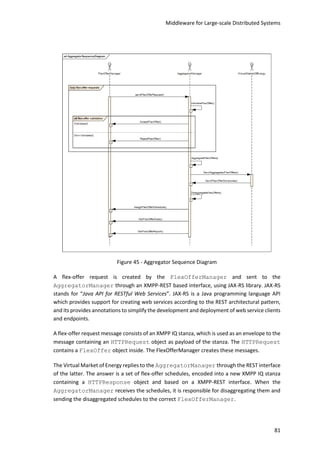
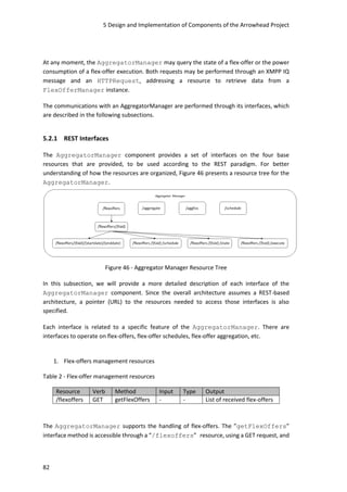
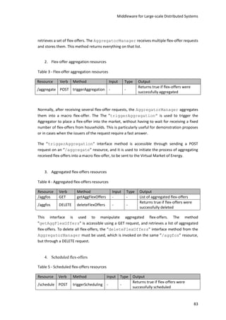
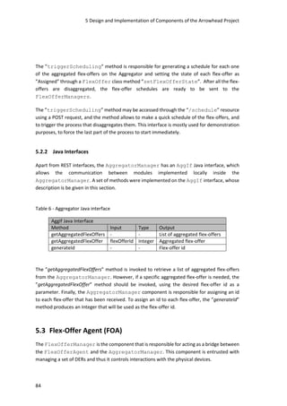
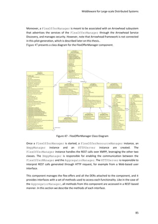
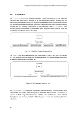
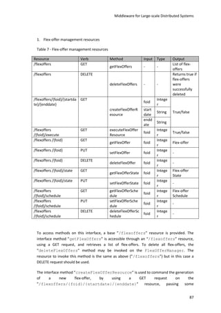
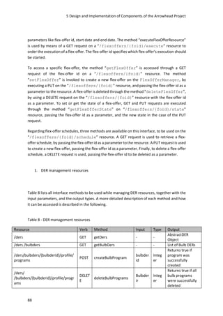
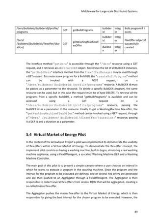
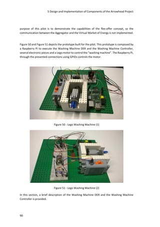


![99
7 Bibliografia
[1] G. Colouris, J. Dollimore e G. Blair, "Distributed Systems – Concept and Design" 5th
Edition Book, 2012.
[2] N. A. Lynch, "Distributed Algorithms", Morgan Kaufmann, 1996.
[3] A. Tanenbaum e M. Van Steen, "Distributed Systems: Principles and Paradigms", 2
Edition, 2007.
[4] Carnot Institutes’ Information Communication Technologies and Micro Nano
Technologies, “Smart networked objects and internet of things,” 2010.
[5] L. Atzori, A. Iera e G. Morabito, “The Internet of Things: A survey,” Computer Networks,
vol. 54, nº 15, pp. 2787-2805, 2010.
[6] G. Kortuem, F. Kawsar, D. Fitton e V. Sundramoorthy, “Smart objects as building blocks
for the Internet of things,” Internet Computing, IEEE, vol. 14, nº 1, pp. 44 - 51, 2009.
[7] D. Le-Phuoc, A. Polleres, M. Hauswirth, G. Tummarello e C. Morbidoni, “Rapid
prototyping of semantic mash-ups through semantic web pipes,” WWW '09 Proceedings
of the 18th international conference on World wide web, pp. 581-590, 2009.
[8] D. I. Wolinsky, A. Agrawa, P. O. Boykin, R. J. Davis, A. Ganguly, V. Paramygin, Y. P. Sheng
e R. J. Figueiredo, “Design of Virtual Machine Sandboxes for Distributed Computing in
Wide-area Overlays of Virtual Workstations,” Virtualization Technology in Distributed
Computing, 2006. VTDC 2006. First International Workshop, 2006.
[9] R. Figueiredo, P. Dinda e J. Fortes, “A case for grid computing on virtual machines,”
2003.](https://image.slidesharecdn.com/92f87b03-0698-478e-aa11-0553917d09f4-161208174943/85/Cesar-Teixeira-Middleware-for-Large-scale-Distributed-Systems-115-320.jpg)
![7 Bibliografia
100
[10] D. Marshall, “Top 10 Benefits of Server Virtualization,” 2 November 2011. [Online].
Available: http://www.infoworld.com/article/2621446/server-virtualization/top-10-
benefits-of-server-virtualization.html. [Acedido em 28 January 2015].
[11] B. Lampson, M. Abadi, M. Burrows e E. Wobber, “Authentication in Distributed Systems:
Theory and Practice,” em ACM Trans. Computer Systems 10, 1992.
[12] P. Artigas e M. Ferdman, “Centralized vs Decentralized: Allocation in Distributed
Systems,” 2000.
[13] G. M. Weiss e J. W. Lockhart, “A Comparison of Alternative Client/Server Architectures
for Ubiquitous Mobile Sensor-Based Applications,” Proceedings of the 2012 ACM
Conference on Ubiquitous Computing, 2012.
[14] Z. F. Chen, X. M. Zhang, Q. C. Chen, T. F. Ma, H. Wang e X. Feng, “Design and
Implementation of an Elementary School Online Registration and Enrollment Position
Allocation System Based on Three-Tier Architecture,” Applied Mechanics and Materials,
pp. 1843-1848, August 2013.
[15] B. Xu e C. Lin, “An extended practical three-tier architecture based on middleware,” em
Software Engineering and Service Science (ICSESS), 2013 4th IEEE International
Conference, 2013.
[16] R. Nandakumar, K. K. Chintalapudi, V. Padmanabhan e R. Venkatesan, “Dhwani: Secure
Peer-to-Peer Acoustic NFC,” em SIGCOMM, 2013.
[17] T. Erl, "SOA: Principles of Service Design", Prentice Hall, 2007.
[18] C. Wu, B. Li e S. Zhao, “Characterizing Peer-to-Peer Streaming Flows,” IEEE Journal on
Selected Areas in Communications, vol. 25, 2007.
[19] A. Yahyavi e B. Kemme, “Peer-to-peer architectures for massively multiplayer online
games: A Survey,” ACM Computing Surveys (CSUR), vol. 46, nº 1, 2013.
[20] Y. Yusufa, A. Gunasekaranb e M. S. Abthorpec, “Enterprise information systems project
implementation: A case study of ERP in Rolls-Royce,” Internation Journal of Production
Economics, vol. 87, nº 3, p. 251–266, 2004.
[21] S. R. Magal e J. Word, Integrated Business Processes with ERP Systems, Wiley, 2012.
[22] “SAP ERP,” SAP, [Online]. Available: http://www.sap.com/portugal/pc/bp/erp.html.
[Acedido em 5 February 2015].](https://image.slidesharecdn.com/92f87b03-0698-478e-aa11-0553917d09f4-161208174943/85/Cesar-Teixeira-Middleware-for-Large-scale-Distributed-Systems-116-320.jpg)
![Middleware for Large-scale Distributed Systems
101
[23] “SAP AG,” SAP, [Online]. Available: http://go.sap.com/index.html. [Acedido em 5
February 2015].
[24] NetSuite, “NetSuite ERP,” NetSuite Inc., 2015. [Online]. Available:
http://www.netsuite.com/portal/products/netsuite/erp.shtml. [Acedido em 5 February
2015].
[25] Microsoft, “Microsoft Dynamics GP,” Microsoft, 2015. [Online]. Available:
http://www.microsoft.com/en-us/dynamics/erp-gp-overview.aspx. [Acedido em 5
February 2015].
[26] “EverQuest Online,” Sony Online Entertainment, 989 Studios, [Online]. Available:
https://www.everquest.com/home. [Acedido em 12 February 2015].
[27] “EVE Online,” CCP Games, 2015. [Online]. Available: https://www.eveonline.com/.
[Acedido em 12 February 2015].
[28] “A Journey Into MMO Server Architecture,” Nexeon Technologies, Inc., 30 May 2013.
[Online]. Available: http://www.mmorpg.com/blogs/FaceOfMankind/052013/25185_A-
Journey-Into-MMO-Server-Architecture. [Acedido em 13 February 2015].
[29] S. M. Kaplan, “Smart Grid. Electrical Power Transmission: Background and Policy Issues,”
2009.
[30] National Institute of Standards and Technology, “NIST Framework and Roadmap for
Smart Grid Interoperability Standards, Release 3.0,” 2014.
[31] United States Department of Energy, “Smart Grid,” [Online]. Available:
http://energy.gov/oe/services/technology-development/smart-grid.
[32] M. Albano, L. L. Ferreira, L. M. Pinho e A. R. Alkhawaja, “Message-oriented middleware
for smart grids,” Computer Standards & Interfaces, vol. 38, pp. 133-143, 2015.
[33] V. Gungor, “A Survey on Smart Grid Potential Applications and Communication
Requirements,” IEEE Trans. on Industrial Informatics, vol. 9, nº 1, pp. 28-42, 2013.
[34] F. Kennel, D. Gorges e S. Liu, “Energy Management for Smart Grids With Electric Vehicles
Based on Hierarchical MPC,” IEEE Trans. on Industrial Informatics, vol. 9, nº 3, pp. 1528-
1537, 2013.
[35] “Smart Grid Project,” Provincial Electricity Authority (PEA), 2014. [Online]. Available:
http://www.powergenasia.com/conference/smartmeter.html. [Acedido em 2015].](https://image.slidesharecdn.com/92f87b03-0698-478e-aa11-0553917d09f4-161208174943/85/Cesar-Teixeira-Middleware-for-Large-scale-Distributed-Systems-117-320.jpg)
![7 Bibliografia
102
[36] A. Bari, J. Jiang, W. Saas e A. Jaekel, “Challenges in the Smart Grid Applications: An
Overview,” International Journal of Distributed Sensor Networks, 2014.
[37] M. Albano, L. L. Ferreira e L. M. Pinho, “Convergence of Smart Grid ICT architectures for
the last mile,” Industrial Informatics, IEEE Transactions, vol. 11, nº 1, pp. 187-197, 2015.
[38] C. Teixeira, M. Albano, A. Skou, L. P. Dueñas, F. Antonacci, R. Ferreira, K. L. Pedersen e S.
Scalari, “Convergence to the European Energy Policy in European countries: case studies
and comparison,” Social Technologies Resarch Journal, vol. 4, nº 1, pp. 7-18, 2014.
[39] “IEEE Standards Association,” IEEE, 2015. [Online]. Available: http://standards.ieee.org/.
[40] S. Browna, D. Pykea e P. Steenhof, “Electric vehicles: The role and importance of
standards in an emerging market,” Energy Policy, vol. 38, nº 7, pp. 3797-3806, 2010.
[41] “Common Information Model Standard,” Distributed Management Task Force, Inc.,
2015. [Online]. Available: http://www.dmtf.org/standards/cim. [Acedido em February
2015].
[42] J.J.Simmins, “The impact of PAP 8 on the Common Information Model (CIM),” Power
Systems Conference and Exposition (PSCE), 2011 IEEE/PES, 2011.
[43] Distributed Management Task Force, Inc., “Common Information Model (CIM)
Infrastructure Specification,” Distributed Management Task Force, Inc. (DMTF), 2005.
[44] Distributed Management Task Force, Inc., “Common Information Model (CIM)
Schemas,” Distributed Management Task Force, Inc. (DMTF), 2015.
[45] “IEC Technical Committee,” IEC TC 57, 2015. [Online]. Available:
http://tc57.iec.ch/index-tc57.html.
[46] “Core IEC Standards,” International Electrotechnical Commission, 2015. [Online].
Available: http://www.iec.ch/smartgrid/standards/. [Acedido em February 2015].
[47] R. G. Hollands, “Will the real smart city please stand up?,” City: analysis of urban trends,
culture, theory, policy, action, vol. 12, nº 3, pp. 303-320, 2008.
[48] A. Caragliu, C. D. Bo e P. NijKamp, “Smart cities in Europe,” 3rd Central European
Conference in Regional Science – CERS, 2009.
[49] Department for Business Innovation & Skills, “Smart Cities - Background Paper,” United
Kingdom Government, 2013.](https://image.slidesharecdn.com/92f87b03-0698-478e-aa11-0553917d09f4-161208174943/85/Cesar-Teixeira-Middleware-for-Large-scale-Distributed-Systems-118-320.jpg)
![Middleware for Large-scale Distributed Systems
103
[50] M. Barr e A. Massa, Programming Embedded Systems: With C and GNU Development
Tools, O'Reilly, 2007.
[51] S. Heath, Embbeded Systems Design, Newnes, 2003.
[52] EdgeFX, “Understanding of Embedded Systems,” EdgeFX Kits & Solutions, 2015. [Online].
Available: http://www.edgefxkits.com/blog/embedded-systems-with-applications/.
[53] H. Koptez, Real-Time Systems: Design Principles for Distributed Embedded Applications,
Springer, 2011.
[54] M. A. Vouk, “Cloud computing — Issues, research and implementations,” Information
Technology Interfaces, 2008.
[55] Microsoft, “Chapter 1: Service Oriented Architecture (SOA),” Microsoft, [Online].
Available: https://msdn.microsoft.com/en-us/library/bb833022.aspx. [Acedido em
February 2015].
[56] A. L. Diaz, “Lessons Learned: Business Agility through Open Standards & Cloud,”
[Online]. Available: http://www.slideshare.net/angelluisdiaz/up2011-diazibm-
cloudstandards.
[57] Dropbox, “Dropbox,” Dropbox, [Online]. Available: https://www.dropbox.com.
[58] Box, “Box,” Box, [Online]. Available: https://www.box.com.
[59] S. Ghosh, Distributed Systems: An Algorithmic Approach, Second Edition, CRC Press,
2014.
[60] L. Harte, Introduction to Data Multicasting, 2008.
[61] K. Geihs, “Middleware Challenges Ahead,” 2001.
[62] E. Curry, “Message-oriented Middleware,” 2004.
[63] IBM, “IBM Websphere Message Broker,” IBM, [Online]. Available:
http://www.ibm.com/software/integration/wbimessagebroker.
[64] “Simple (or Streaming) Text Oriented Messaging Protocol (STOMP),” [Online]. Available:
https://stomp.github.io/.
[65] “Message Queue Telemetry Transport (MQTT),” [Online]. Available: http://mqtt.org/.
[66] “RabbitMQ – AMQP Concepts,” [Online]. Available:
http://www.rabbitmq.com/tutorials/amqp-concepts.html.](https://image.slidesharecdn.com/92f87b03-0698-478e-aa11-0553917d09f4-161208174943/85/Cesar-Teixeira-Middleware-for-Large-scale-Distributed-Systems-119-320.jpg)
![7 Bibliografia
104
[67] M. K. Duncan e C. , “AMQP 0.9.1 Model Explained,” [Online]. Available:
http://www.rubydoc.info/github/ruby-
amqp/amqp/master/file/docs/AMQP091ModelExplained.textile.
[68] A. Videla e J. J. W. Williams, RabbitMQ in Action: Distributed messaging for everyone,
Manning, 2012.
[69] “Erlang Official Website,” [Online]. Available: http://www.erlang.org/.
[70] “Extensible Messaging and Presence Protocol (XMPP) Official Website,” [Online].
Available: http://xmpp.org/.
[71] P. Saint-Andre, “Extensible Messaging and Presence Protocol (XMPP): Core,” [Online].
Available: http://www.ietf.org/rfc/rfc3920.txt.
[72] “International Engineering Task Force (IEFT) Official Website,” [Online]. Available:
http://ieft.net/.
[73] P. Saint-Andre, K. Smith e R. Tronçon, XMPP: The Definitive Guide - Building Real-Time
Applications with Jabber Technologies, O'Reilly, 2009.
[74] J. Moffitt, Professional XMPP Programming with JavaScript and jQuery, Wrox, 2010.
[75] “XEP-0045: Multi-User Chat Specification,” [Online]. Available:
http://xmpp.org/extensions/xep-0045.html.
[76] “XEP-0060: Publish-Subscribe Specification,” [Online]. Available:
http://www.xmpp.org/extensions/xep-0060.html.
[77] “XMPP Extensions (XEPs) Official Website,” [Online]. Available: http://xmpp.org/xmpp-
protocols/xmpp-extensions/.
[78] “XEP-0332: HTTP over XMPP transport,” [Online]. Available:
http://xmpp.org/extensions/xep-0332.html.
[79] “XEP-0114: Jabber Component Protocol,” [Online]. Available:
http://xmpp.org/extensions/xep-0114.html.
[80] “Ejabberd Official Website,” [Online]. Available: https://www.ejabberd.im.
[81] “Ignite Realtime: Openfire Official Website,” [Online]. Available:
http://www.igniterealtime.org/projects/openfire/.
[82] “Data Distribution Service for Real-Time Systems Specification,” Object Management
Group, Inc. (OMG), 2005.](https://image.slidesharecdn.com/92f87b03-0698-478e-aa11-0553917d09f4-161208174943/85/Cesar-Teixeira-Middleware-for-Large-scale-Distributed-Systems-120-320.jpg)
![Middleware for Large-scale Distributed Systems
105
[83] J. Sanchez-Monederoa, J. Povedano-Molinab, J. M. Lopez-Vegab e J. M. Lopez-Solerb,
“Bloom filter-based discovery protocol for DDS middleware,” Journal of Parallel and
Distributed Computing, 2011.](https://image.slidesharecdn.com/92f87b03-0698-478e-aa11-0553917d09f4-161208174943/85/Cesar-Teixeira-Middleware-for-Large-scale-Distributed-Systems-121-320.jpg)

The document is a dissertation written in Portuguese for a Master's degree in Computer Engineering. It discusses middleware for large-scale distributed systems. The introduction provides context for the thesis, stating its objectives are to study the state of the art of middleware applied to large-scale distributed systems and demonstrate how middleware can facilitate system design and development. It then outlines the structure of the dissertation, which includes chapters on the state of the art, distributed systems middleware, design and implementation of components for two projects (ENCOURAGE and Arrowhead) and conclusions.