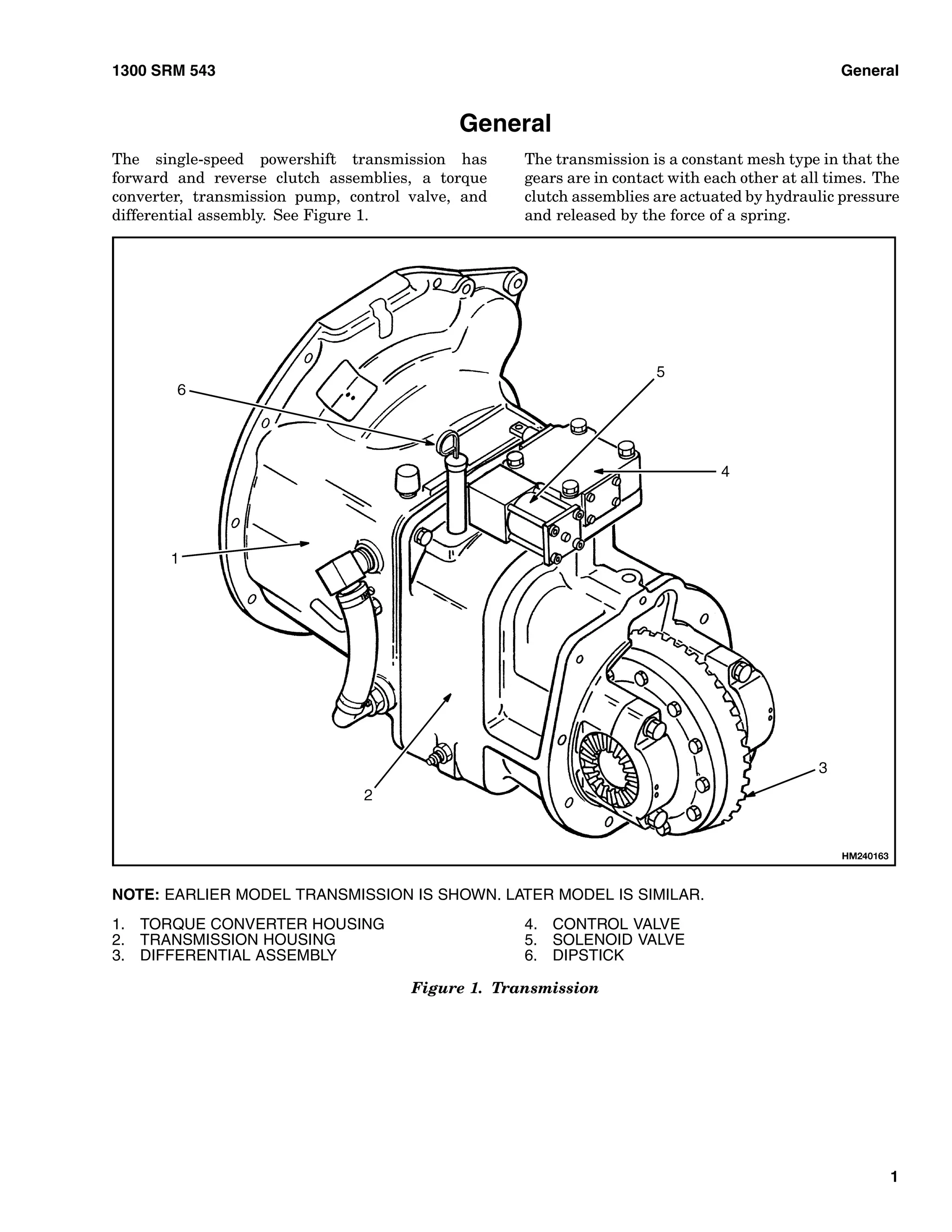
The document provides an overview of the components and operation of a single-speed powershift transmission, including:
1) The transmission contains forward and reverse clutch assemblies, a torque converter, transmission pump, control valve, and differential assembly to transfer power from the engine to the wheels.
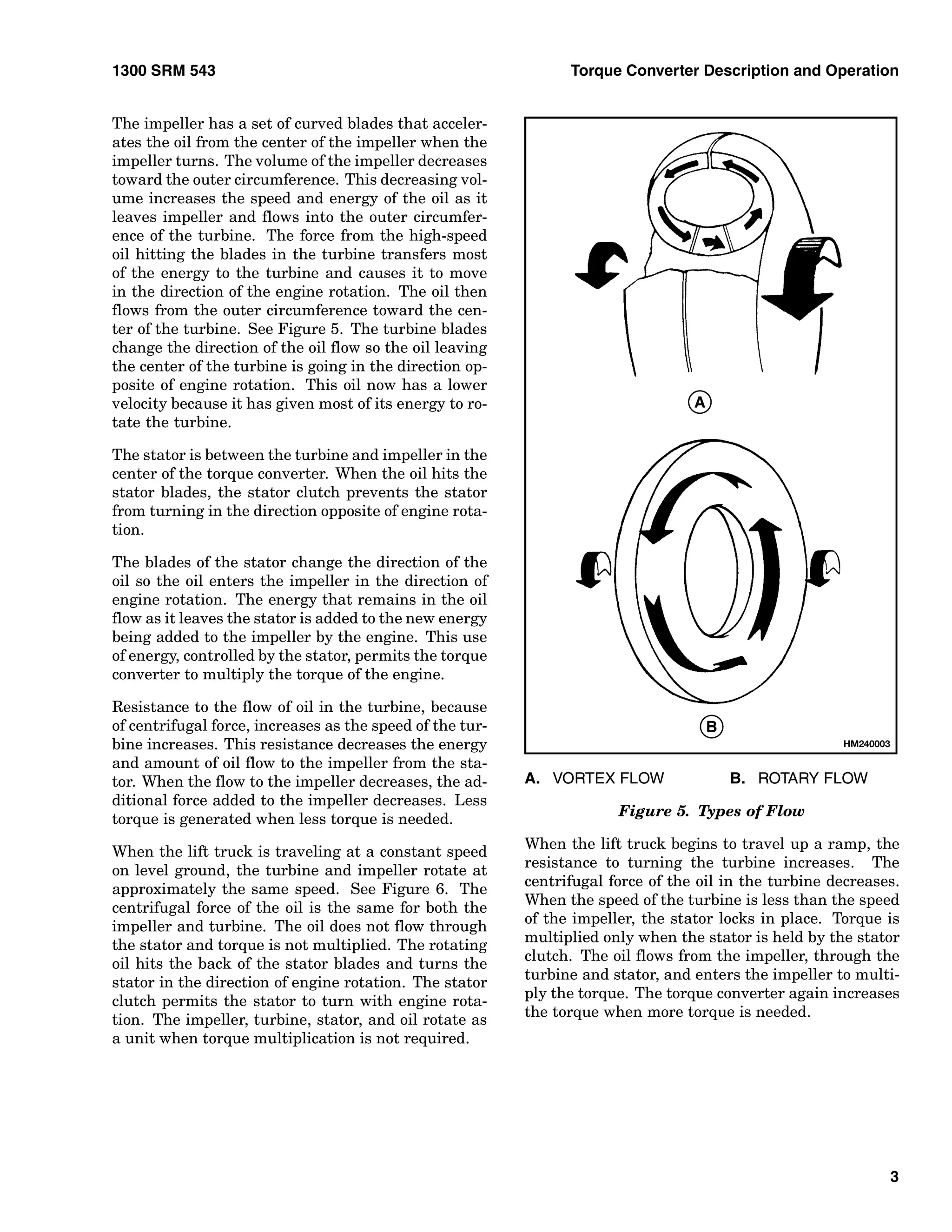
2) The torque converter uses fluid coupling between an impeller and turbine to transfer power from the engine to the transmission, and can multiply engine torque through a stator clutch mechanism.
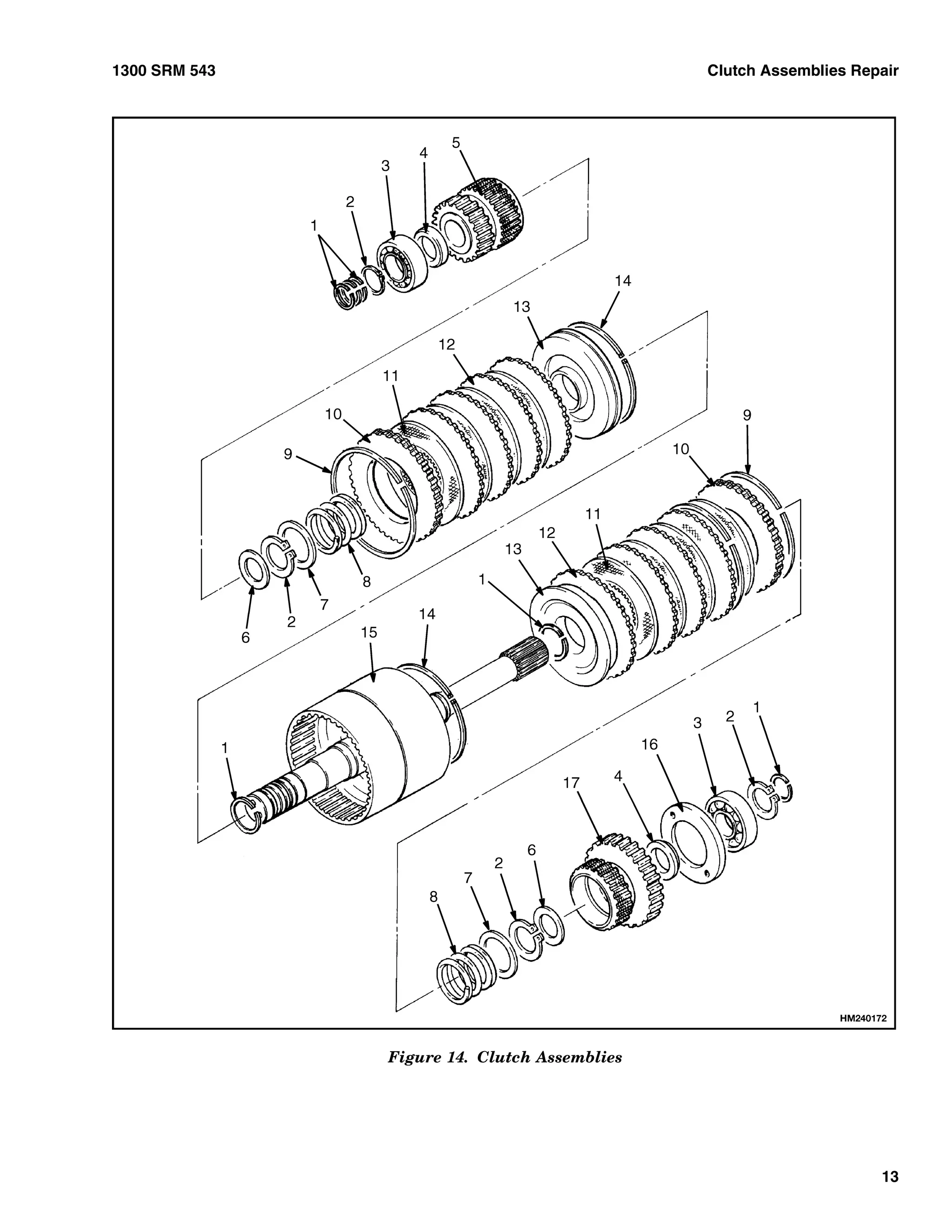
3) The forward and reverse clutch assemblies use hydraulic pressure to engage friction discs and transfer power between the input shaft and either the forward or reverse gears to select transmission direction.
The document provides information about the components and operation of a manual transmission clutch system. It describes the purpose and function of key parts like the clutch disc, pressure plate, flywheel, and pilot bearing. It explains that depressing the clutch pedal disengages the clutch to allow gear changes, while releasing the pedal engages the clutch to transmit power from the engine to the transmission.
This Presentation gives a Brief of different Systems in a Vehicle like Transmission, Lubrication and Different Sensors used. Some other systems will be described in the part 2 presentation.
Clutch is a mechanism which enables the rotary motion of one shaft to be transmitted, when desired, to a second shaft the axis of which is coincident with that of first.
Clutch is used to engage or disengage the engine to the transmission or gear box.
The document provides information about the key components of a car, including:
- The engine, which uses a four-stroke cycle to power the car. It intakes, compresses, powers and exhausts air and fuel in four strokes to drive the crankshaft.
- The transmission, which uses planetary gear sets and hydraulic components like clutches, bands, and a torque converter to transfer power from the engine to the wheels through different gear ratios.
- The braking system, which uses disc or drum brakes on each wheel and a hydraulic system or handbrake to slow and stop the car.
- Other components like the speedometer, fuel gauge, air conditioning, and sound system
The document discusses the transmission system of automobiles. It defines the transmission system as the mechanism that transmits power from the engine to the driving wheels. The main components of the transmission system are identified as the clutch, gearbox, propeller shaft, universal joints, rear axle, and differential. The document also discusses the requirements of an effective transmission system and describes the operating principles of different types of transmission systems, including manual transmission, hydraulic transmission using fluid couplings or torque converters, and automatic transmission using planetary gears.
Power assisted brakes use either hydraulic or vacuum pressure to reduce the amount of force needed to press the brake pedal. Hydraulic systems use pressure from the power steering pump or an air compressor, while vacuum systems use pressure from the intake manifold. Both types work by creating pressure on one side of a booster piston to multiply the force applied through the brake pedal to the master cylinder. When the pedal is pressed, it closes off the pressure source and applies hydraulic pressure to the brakes. Releasing the pedal vents the booster pressure and allows the pedal to return freely. Servo brakes provide additional braking power needed for heavier vehicles through mechanical, hydraulic, or vacuum assisted systems.
The document discusses different types of clutches used in vehicles. It describes a clutch as a mechanical device that connects and disconnects two rotating shafts to facilitate transmission of power and motion. The main types discussed are single plate clutches, multi-plate clutches, cone clutches, and centrifugal clutches. A single plate clutch uses a flywheel, pressure plate, clutch disc/plate, and release bearing. A multi-plate clutch has multiple clutch plates to transmit higher torque. A cone clutch uses a cone shape for contact rather than plates. A centrifugal clutch uses centrifugal force from rotation to engage.
The document discusses automobile engines. It begins by classifying engines based on the type of fuel used, ignition type, operating cycle, number of strokes, valve location, design, cylinder arrangement, air intake, cooling type, and application. The main components of an internal combustion engine are then described, including the cylinder, cylinder head, piston, valves, manifolds, connecting rod, crank, flywheel, engine block, cam, piston rings, and crankcase. Four-stroke petrol and diesel engine cycles are illustrated and compared. Two-stroke petrol and diesel engines are also discussed and compared to four-stroke engines.
This document provides an overview of the key topics covered in an automatic transmission diagnosis course. It describes the function of major automatic transmission components like the torque converter and its three parts, planetary gear sets and how they provide different speed and torque ratios, and the types of clutching devices used to hold gears including multi-plate clutches, brake bands, and one-way clutches. It also explains how these components work together to provide the gear ratios used in automatic transmissions.
The document discusses the steering system of an automobile. It begins by introducing the steering system and describing how it converts rotational movement of the steering wheel into angular turns of the front wheels. It then discusses specifics of power steering systems, including their layout and components. It provides details on the Rane power steering system used in the vehicle, including its components like the gear box and control valve. It describes how the system functions during left and right turns through the movement of the control valve and fluid flow.
The document provides information about the steering system used in ALS MKIII vehicles. It describes the integral power steering gearbox as having a manual steering mechanism along with a hydraulic control valve and power cylinder integrated into a single compact unit. The gearbox uses a rotary control valve to direct hydraulic fluid to assist rack movement during steering. The document outlines procedures for filling, bleeding, and adjusting the power steering system, including setting axle stops and adjusting poppet valves and worm shaft preload. Faults and their probable causes are listed with remedies.
This document is a seminar report on torque converters that includes:
1) An introduction describing torque converters and their role in automatic transmissions.
2) Descriptions of the major components of a torque converter including the impeller, turbine, and stator.
3) An explanation of how torque converters function in stall, acceleration, and coupling phases.
An automatic transmission uses hydraulic pressure controlled by a transmission ECU to shift gears smoothly and efficiently. It contains planetary gears that provide different gear ratios depending on which elements are locked. A torque converter transfers power from the engine to the transmission using fluid coupling until a lock-up clutch engages for improved efficiency. Modern electronically controlled automatic transmissions use sensors and solenoids to optimize gear shifts for performance and fuel economy.
The document discusses the transmission system of an automobile. It defines the transmission system as the mechanism that transmits power from the engine to the driving wheels. The main components of the transmission system are the clutch, gearbox, propeller shaft, universal joints, rear axle, wheels, and tires. The document also discusses different types of transmission systems, including hydraulic transmission systems like fluid couplings and torque converters. It provides details on how manual and automatic transmissions work, including the stages involved and a comparison of the two systems.
An automatic transmission uses a torque converter, gear train, and hydraulic system to shift gears automatically based on engine load and vehicle speed. The torque converter connects the engine to the transmission and transfers power through fluid. It multiplies torque for better acceleration. The gear train includes planetary gear sets that provide multiple gear ratios. Hydraulic pressure acts through the transmission fluid to engage clutches and bands, producing gear shifts without driver input as the vehicle speed increases.
This training report summarizes the trainees' learning about diesel locomotives. It provides details on:
1. The history and development of diesel locomotives from Rudolf Diesel's invention in the late 19th century to their widespread use in the 20th century.
2. The key components and systems of a diesel-electric locomotive, including the diesel engine, generator, traction motors, bogies, braking systems, governor, and radiator.
3. Descriptions of the workings of specific parts like the Woodward and electro-hydraulic governors, bogies, traction motors, and air/vacuum braking systems.
Volvo EC360 LC EC360LC Excavator Service Repair Manual Instant Download.pdffijsekkkdmdm3e
The document provides information on various engine components and systems:
- The engine is a 6-cylinder, turbocharged diesel engine with a cast iron block and head.
- It has a lubrication system that supplies oil to rotating components via forced lubrication from an oil pump.
- The fuel injection system uses a high-pressure fuel pump to directly inject fuel into the combustion chamber, with excess fuel returned to the tank.
- Other sections provide details on engine mounting, valve and injector adjustment procedures, and descriptions of the fuel tank.
Volvo EC360 LC EC360LC Excavator Service Repair Manual Instant Download.pdff8iosedkdm3e
The document provides information on adjusting the valves and injectors of Cummins LTA 10-C & M11-C engines. It describes the engine as a 6-cylinder, 4-stroke diesel engine with specifications provided. Valves and injectors must be adjusted every 1,500 hours or 1 year to specifications of 0.35mm for intake valves and 0.68mm for exhaust valves. The process of adjusting the valves and injectors to the correct clearance using feeler gauges at each pulley index mark is described in detail over multiple steps.
Volvo EC360 LC EC360LC Excavator Service Repair Manual Instant Download.pdfrou774513po
The document provides information on adjusting the valves and injectors of Cummins LTA 10-C & M11-C engines. It describes the engine as a 6-cylinder, 4-stroke diesel engine with specifications provided. Valves and injectors must be adjusted every 1,500 hours or 1 year to specifications of 0.35mm for intake valves and 0.68mm for exhaust valves. The process of adjusting the valves and injectors to the correct clearance using feeler gauges at each pulley index mark is described in detail over multiple steps.
Volvo EC360 LC EC360LC Excavator Service Repair Manual Instant Download.pdfzhenchun51
The document provides information on various engine components and systems:
- The engine is a 6-cylinder, turbocharged diesel engine with a cast iron block and head.
- It has a lubrication system that supplies oil to rotating components via forced lubrication from an oil pump.
- The fuel injection system uses a high-pressure fuel pump to directly inject fuel into the combustion chamber, with excess fuel returned to the tank.
- Other sections provide details on engine mounting, valve and injector adjustment procedures, and descriptions of the fuel tank.
Volvo EC360 LC EC360LC Excavator Service Repair Manual Instant Download.pdfzu0582kui
The document provides information on engine components and systems:
- The engine is a 6-cylinder diesel with a cast iron block and head, direct injection, and turbocharging.
- It has a lubrication system that supplies oil to rotating components through forced lubrication from an oil pump.
- The fuel injection system uses a high-pressure fuel pump to directly inject fuel into the combustion chamber, with excess returning to the tank.
- Other sections provide details on valve and injector adjustment procedures, engine mounting, and fuel tank components.
Volvo EC360 LC EC360LC Excavator Service Repair Manual Instant Download.pdflunrizan628
The document provides information on various engine systems:
- The engine is a 6-cylinder diesel with a cast iron block and head, direct injection, and turbocharging.
- It has a lubrication system that supplies oil to rotating components through forced lubrication from an oil pump.
- The fuel injection system uses a high-pressure fuel pump to directly inject fuel into the combustion chamber, with excess returning to the tank.
- Other sections provide details on valve and injector adjustment procedures, engine mounting, and descriptions of the fuel tank.
Volvo EC360 LC EC360LC Excavator Service Repair Manual Instant Download.pdffapanhe306271
The document provides information on engine components and systems:
- The engine is a 6-cylinder diesel with a cast iron block and head, direct injection, and turbocharging.
- It has a lubrication system that supplies oil to rotating components through forced lubrication from an oil pump.
- The fuel injection system uses highly pressurized fuel from a fuel pump that is directly injected into the combustion chamber, with excess fuel returned to the tank.
- Proper adjustment of valves and injectors is required according to the maintenance schedule.
The document discusses the transmission system of automobiles. It defines the transmission system and its main components which transmit power from the engine to the driving wheels. These include the clutch, gearbox, propeller shaft, universal joints, rear axle, and differential. It describes the requirements of an effective transmission system and the operating principles of different types of transmission systems including manual, automatic, hydraulic, and their main units.
The document discusses the transmission system of automobiles. It defines the transmission system as the mechanism that transmits power from the engine to the driving wheels. The main components of the transmission system are identified as the clutch, gearbox, propeller shaft, universal joints, rear axle, and wheels/tires. The requirements of the transmission system and the types of transmission systems including manual, hydraulic, and automatic are also summarized.
The document discusses the transmission system of automobiles. It defines the transmission system and its main components which transmit power from the engine to the driving wheels. These include the clutch, gearbox, propeller shaft, universal joints, rear axle, and differential. It describes the requirements of an effective transmission system and provides details on manual and automatic transmission systems, including their components and operating principles. It also compares manual and automatic transmissions.
New holland e30 c cab tier 4 final engine mini excavator service repair manualudfjjjdkksmmd
This document is a service manual for the E30C mini excavator. It contains sections covering the engine, hydraulic systems, frames and ballasting, tracks and track suspension, electrical systems, booms, dippers, buckets, dozer blades, and the platform, cab, bodywork, and decals. Safety information is provided, noting signal words for dangers, warnings, and cautions regarding potential hazards. The manual is intended to guide qualified service personnel in maintenance and repair work.
Komatsu pc200 lc 6 crawler excavator parts catalogue manual - sn 80001 and upudfjjjdkksmmd
This document provides parts information for various engine mount configurations for a PC200LC-6 excavator made by Hitachi between 80001-110540 serial numbers for overseas markets. It includes the part numbers, names, quantities and applicable serial number ranges for each engine mount configuration. The document is divided into sections for different component groups like engine, undercarriage, work equipment etc.
Hyster g004 (s100 ftbcs) forklift service repair manualudfjjjdkksmmd
This document provides repair procedures for manual and electronic main control valves used in hydraulic lift trucks. It describes:
- There are two main control valve types - manual and electronic. Both are mounted to the cowl.
- The electronic main control valve incorporates an emergency lowering valve and is divided into steering control, lift/lower, tilt, auxiliary, and outlet sections.
- Removal procedures include disconnecting wiring harnesses and hydraulic hoses, removing the steering control unit, and removing O-rings from the main control valve.
More Related Content
Similar to Hyster d010 (s25 xm) forklift service repair manual
This document provides an overview of the key topics covered in an automatic transmission diagnosis course. It describes the function of major automatic transmission components like the torque converter and its three parts, planetary gear sets and how they provide different speed and torque ratios, and the types of clutching devices used to hold gears including multi-plate clutches, brake bands, and one-way clutches. It also explains how these components work together to provide the gear ratios used in automatic transmissions.
The document discusses the steering system of an automobile. It begins by introducing the steering system and describing how it converts rotational movement of the steering wheel into angular turns of the front wheels. It then discusses specifics of power steering systems, including their layout and components. It provides details on the Rane power steering system used in the vehicle, including its components like the gear box and control valve. It describes how the system functions during left and right turns through the movement of the control valve and fluid flow.
The document provides information about the steering system used in ALS MKIII vehicles. It describes the integral power steering gearbox as having a manual steering mechanism along with a hydraulic control valve and power cylinder integrated into a single compact unit. The gearbox uses a rotary control valve to direct hydraulic fluid to assist rack movement during steering. The document outlines procedures for filling, bleeding, and adjusting the power steering system, including setting axle stops and adjusting poppet valves and worm shaft preload. Faults and their probable causes are listed with remedies.
This document is a seminar report on torque converters that includes:
1) An introduction describing torque converters and their role in automatic transmissions.
2) Descriptions of the major components of a torque converter including the impeller, turbine, and stator.
3) An explanation of how torque converters function in stall, acceleration, and coupling phases.
An automatic transmission uses hydraulic pressure controlled by a transmission ECU to shift gears smoothly and efficiently. It contains planetary gears that provide different gear ratios depending on which elements are locked. A torque converter transfers power from the engine to the transmission using fluid coupling until a lock-up clutch engages for improved efficiency. Modern electronically controlled automatic transmissions use sensors and solenoids to optimize gear shifts for performance and fuel economy.
The document discusses the transmission system of an automobile. It defines the transmission system as the mechanism that transmits power from the engine to the driving wheels. The main components of the transmission system are the clutch, gearbox, propeller shaft, universal joints, rear axle, wheels, and tires. The document also discusses different types of transmission systems, including hydraulic transmission systems like fluid couplings and torque converters. It provides details on how manual and automatic transmissions work, including the stages involved and a comparison of the two systems.
An automatic transmission uses a torque converter, gear train, and hydraulic system to shift gears automatically based on engine load and vehicle speed. The torque converter connects the engine to the transmission and transfers power through fluid. It multiplies torque for better acceleration. The gear train includes planetary gear sets that provide multiple gear ratios. Hydraulic pressure acts through the transmission fluid to engage clutches and bands, producing gear shifts without driver input as the vehicle speed increases.
This training report summarizes the trainees' learning about diesel locomotives. It provides details on:
1. The history and development of diesel locomotives from Rudolf Diesel's invention in the late 19th century to their widespread use in the 20th century.
2. The key components and systems of a diesel-electric locomotive, including the diesel engine, generator, traction motors, bogies, braking systems, governor, and radiator.
3. Descriptions of the workings of specific parts like the Woodward and electro-hydraulic governors, bogies, traction motors, and air/vacuum braking systems.
Volvo EC360 LC EC360LC Excavator Service Repair Manual Instant Download.pdffijsekkkdmdm3e
The document provides information on various engine components and systems:
- The engine is a 6-cylinder, turbocharged diesel engine with a cast iron block and head.
- It has a lubrication system that supplies oil to rotating components via forced lubrication from an oil pump.
- The fuel injection system uses a high-pressure fuel pump to directly inject fuel into the combustion chamber, with excess fuel returned to the tank.
- Other sections provide details on engine mounting, valve and injector adjustment procedures, and descriptions of the fuel tank.
Volvo EC360 LC EC360LC Excavator Service Repair Manual Instant Download.pdff8iosedkdm3e
The document provides information on adjusting the valves and injectors of Cummins LTA 10-C & M11-C engines. It describes the engine as a 6-cylinder, 4-stroke diesel engine with specifications provided. Valves and injectors must be adjusted every 1,500 hours or 1 year to specifications of 0.35mm for intake valves and 0.68mm for exhaust valves. The process of adjusting the valves and injectors to the correct clearance using feeler gauges at each pulley index mark is described in detail over multiple steps.
Volvo EC360 LC EC360LC Excavator Service Repair Manual Instant Download.pdfrou774513po
The document provides information on adjusting the valves and injectors of Cummins LTA 10-C & M11-C engines. It describes the engine as a 6-cylinder, 4-stroke diesel engine with specifications provided. Valves and injectors must be adjusted every 1,500 hours or 1 year to specifications of 0.35mm for intake valves and 0.68mm for exhaust valves. The process of adjusting the valves and injectors to the correct clearance using feeler gauges at each pulley index mark is described in detail over multiple steps.
Volvo EC360 LC EC360LC Excavator Service Repair Manual Instant Download.pdfzhenchun51
The document provides information on various engine components and systems:
- The engine is a 6-cylinder, turbocharged diesel engine with a cast iron block and head.
- It has a lubrication system that supplies oil to rotating components via forced lubrication from an oil pump.
- The fuel injection system uses a high-pressure fuel pump to directly inject fuel into the combustion chamber, with excess fuel returned to the tank.
- Other sections provide details on engine mounting, valve and injector adjustment procedures, and descriptions of the fuel tank.
Volvo EC360 LC EC360LC Excavator Service Repair Manual Instant Download.pdfzu0582kui
The document provides information on engine components and systems:
- The engine is a 6-cylinder diesel with a cast iron block and head, direct injection, and turbocharging.
- It has a lubrication system that supplies oil to rotating components through forced lubrication from an oil pump.
- The fuel injection system uses a high-pressure fuel pump to directly inject fuel into the combustion chamber, with excess returning to the tank.
- Other sections provide details on valve and injector adjustment procedures, engine mounting, and fuel tank components.
Volvo EC360 LC EC360LC Excavator Service Repair Manual Instant Download.pdflunrizan628
The document provides information on various engine systems:
- The engine is a 6-cylinder diesel with a cast iron block and head, direct injection, and turbocharging.
- It has a lubrication system that supplies oil to rotating components through forced lubrication from an oil pump.
- The fuel injection system uses a high-pressure fuel pump to directly inject fuel into the combustion chamber, with excess returning to the tank.
- Other sections provide details on valve and injector adjustment procedures, engine mounting, and descriptions of the fuel tank.
Volvo EC360 LC EC360LC Excavator Service Repair Manual Instant Download.pdffapanhe306271
The document provides information on engine components and systems:
- The engine is a 6-cylinder diesel with a cast iron block and head, direct injection, and turbocharging.
- It has a lubrication system that supplies oil to rotating components through forced lubrication from an oil pump.
- The fuel injection system uses highly pressurized fuel from a fuel pump that is directly injected into the combustion chamber, with excess fuel returned to the tank.
- Proper adjustment of valves and injectors is required according to the maintenance schedule.
The document discusses the transmission system of automobiles. It defines the transmission system and its main components which transmit power from the engine to the driving wheels. These include the clutch, gearbox, propeller shaft, universal joints, rear axle, and differential. It describes the requirements of an effective transmission system and the operating principles of different types of transmission systems including manual, automatic, hydraulic, and their main units.
The document discusses the transmission system of automobiles. It defines the transmission system as the mechanism that transmits power from the engine to the driving wheels. The main components of the transmission system are identified as the clutch, gearbox, propeller shaft, universal joints, rear axle, and wheels/tires. The requirements of the transmission system and the types of transmission systems including manual, hydraulic, and automatic are also summarized.
The document discusses the transmission system of automobiles. It defines the transmission system and its main components which transmit power from the engine to the driving wheels. These include the clutch, gearbox, propeller shaft, universal joints, rear axle, and differential. It describes the requirements of an effective transmission system and provides details on manual and automatic transmission systems, including their components and operating principles. It also compares manual and automatic transmissions.
Similar to Hyster d010 (s25 xm) forklift service repair manual (19)
New holland e30 c cab tier 4 final engine mini excavator service repair manualudfjjjdkksmmd
This document is a service manual for the E30C mini excavator. It contains sections covering the engine, hydraulic systems, frames and ballasting, tracks and track suspension, electrical systems, booms, dippers, buckets, dozer blades, and the platform, cab, bodywork, and decals. Safety information is provided, noting signal words for dangers, warnings, and cautions regarding potential hazards. The manual is intended to guide qualified service personnel in maintenance and repair work.
Komatsu pc200 lc 6 crawler excavator parts catalogue manual - sn 80001 and upudfjjjdkksmmd
This document provides parts information for various engine mount configurations for a PC200LC-6 excavator made by Hitachi between 80001-110540 serial numbers for overseas markets. It includes the part numbers, names, quantities and applicable serial number ranges for each engine mount configuration. The document is divided into sections for different component groups like engine, undercarriage, work equipment etc.
Hyster g004 (s100 ftbcs) forklift service repair manualudfjjjdkksmmd
This document provides repair procedures for manual and electronic main control valves used in hydraulic lift trucks. It describes:
- There are two main control valve types - manual and electronic. Both are mounted to the cowl.
- The electronic main control valve incorporates an emergency lowering valve and is divided into steering control, lift/lower, tilt, auxiliary, and outlet sections.
- Removal procedures include disconnecting wiring harnesses and hydraulic hoses, removing the steering control unit, and removing O-rings from the main control valve.
Hyster d138 (n40 fr) forklift service repair manualudfjjjdkksmmd
This document provides repair procedures for single and double reach carriages on lift trucks. It describes the components of the reach carriages, including the inner and outer frames connected by scissor linkages. It also describes the hydraulic systems that control the reach, tilt, and optional side-shift functions. The summary provides step-by-step instructions for repairs such as replacing forks, removing and installing the side-shift frame, and removing/replacing other components while emphasizing safety precautions.
Hyster d005 (h110 e europe) forklift service repair manualudfjjjdkksmmd
This document provides instructions for servicing GM engines. It describes removing and installing the cylinder head and valve mechanism. Key steps include using a compressor tool to remove the valve springs and retainers, cleaning carbon from the combustion chambers, inspecting the valves and guides for wear, and checking clearances. The valve seats can be repaired with a cutter tool if within specifications; otherwise the cylinder head must be replaced. Rocker arm studs should also be replaced if damaged.
Cummins onan generator set with power command 3100 controller model (dfed ) s...udfjjjdkksmmd
This document is a service manual that provides information for troubleshooting and servicing generator sets and their components. It includes sections on control operation, circuit boards and modules, troubleshooting, control service and calibration, servicing the generator, day tank fuel transfer pumps, optional enclosure fuel tank systems, and wiring diagrams. The manual provides technical specifications and maintenance procedures for various generator set parts.
Case w8 wheel loader service repair manualudfjjjdkksmmd
This document provides specifications for W8, W9, and W10 series E loader engines, including general information on engine type, size, speed, lubrication system, and fuel systems. It lists details on components like pistons, main bearings, oil pumps, filters, injection pumps, injectors, and distributors for both diesel and spark ignition engine variants. The specifications are broken into series covering general engine info, engine blocks, fuel systems, hydraulics, steering, powertrain, brakes, electrical systems, and mounted equipment.
Case 1121 g tier 2 wheel loader service repair manualudfjjjdkksmmd
This 3-page service manual provides maintenance instructions for CNH Industrial Italia S.p.A. wheel loaders models 1021G and 1121G. It contains sections on the engine, transmission, four-wheel drive system, front and rear axle systems, brakes, hydraulic systems, frames and ballasting, steering, wheels, cab climate control, electrical systems, front loader and bucket, platform/bodywork, and safety procedures. Technicians are instructed to follow all safety precautions and only perform authorized repairs after stopping the engine and relieving hydraulic pressure.
Case 1121 f tier 4 wheel loader service repair manualudfjjjdkksmmd
This document is a service manual that contains contents, introduction, and torque specifications for various components of an engine, transmission, drivetrain, axles, brakes, hydraulics, steering, wheels, cab climate control, and electrical systems. The document provides over 50 section references to more detailed information about each system, and includes over 30 torque specifications for fasteners and components throughout the machine.
Case 1121 f tier 2 wheel loader service repair manualudfjjjdkksmmd
This document provides torque specifications for various components on a Case 1021F and 1121F wheel loader, including engines, axles, brakes, drivetrains, hydraulics, and other systems. Torque values are given for items like alternator and battery terminals, axle housing and wheel bolts, transmission mounting bolts, engine and chassis mounting hardware, fuel tank and sender fasteners, and hydraulic pump fittings. The document is intended to ensure components are properly tightened during maintenance and repair.
Case 721 g wheel loader zbar eh, new cab tier4b na wheel loader service repai...udfjjjdkksmmd
This document is a service manual for Case 621G and 721G wheel loaders with Tier 4B engines. It contains sections covering the engine, transmission, axles, brakes, hydraulics, frames, steering, wheels, cab climate control, and electrical systems. It also includes sections specific to the front loader arms and buckets.
Case 721 f tier 4b (final) wheel loader service repair manualudfjjjdkksmmd
This service manual provides instructions for maintenance and repair of Case wheel loaders models 621F and 721F with Tier 4B engines. The manual covers the engine, transmission, four-wheel drive system, front and rear axle systems, brakes, hydraulic systems, frames, steering, wheels, cab climate control, electrical systems, front loader and bucket, platform, cab, and decals. Safety precautions are provided, and only authorized personnel should perform repairs.
Case 721 e tier3 z bar. wheel loader service repair manual [n7ae12500 - ]udfjjjdkksmmd
This document is a service manual for the 721E wheel loader. It contains information on the engine, transmission, front and rear axle systems, brakes, hydraulic systems, steering, wheels, cab climate control, electrical systems, and platform/cab components. The manual is organized by system with section numbers that correspond to components and procedures. It provides specifications, descriptions of how systems work, diagnostic and troubleshooting information, and service procedures.
Case 521 f tier ii wheel loader service repair manualudfjjjdkksmmd
This document provides instructions for removing the engine from a 521F wheel loader. The steps include draining fluids, disconnecting wiring harnesses and hoses, removing mounting hardware, and detaching components like the air cleaner, radiator, and drive belts. Safety precautions are outlined at the beginning to release pressures and discharge accumulators. Sections of the repair manual covering specific engine systems are referenced for further repair instructions.
Dahua provides a comprehensive guide on how to install their security camera systems. Learn about the different types of cameras and system components, as well as the installation process.
EV Charging at MFH Properties by Whitaker JamiesonForth
Whitaker Jamieson, Senior Specialist at Forth, gave this presentation at the Forth Addressing The Challenges of Charging at Multi-Family Housing webinar on June 11, 2024.
Implementing ELDs or Electronic Logging Devices is slowly but surely becoming the norm in fleet management. Why? Well, integrating ELDs and associated connected vehicle solutions like fleet tracking devices lets businesses and their in-house fleet managers reap several benefits. Check out the post below to learn more.
Charging and Fueling Infrastructure Grant: Round 2 by Brandt HertensteinForth
Brandt Hertenstein, Program Manager of the Electrification Coalition gave this presentation at the Forth and Electrification Coalition CFI Grant Program - Overview and Technical Assistance webinar on June 12, 2024.
Charging Fueling & Infrastructure (CFI) Program Resources by Cat PleinForth
Cat Plein, Development & Communications Director of Forth, gave this presentation at the Forth and Electrification Coalition CFI Grant Program - Overview and Technical Assistance webinar on June 12, 2024.
Expanding Access to Affordable At-Home EV Charging by Vanessa WarheitForth
Vanessa Warheit, Co-Founder of EV Charging for All, gave this presentation at the Forth Addressing The Challenges of Charging at Multi-Family Housing webinar on June 11, 2024.
Charging Fueling & Infrastructure (CFI) Program by Kevin MillerForth
Kevin Miller, Senior Advisor, Business Models of the Joint Office of Energy and Transportation gave this presentation at the Forth and Electrification Coalition CFI Grant Program - Overview and Technical Assistance webinar on June 12, 2024.
Understanding Catalytic Converter Theft:
What is a Catalytic Converter?: Learn about the function of catalytic converters in vehicles and why they are targeted by thieves.
Why are They Stolen?: Discover the valuable metals inside catalytic converters (such as platinum, palladium, and rhodium) that make them attractive to criminals.
Steps to Prevent Catalytic Converter Theft:
Parking Strategies: Tips on where and how to park your vehicle to reduce the risk of theft, such as parking in well-lit areas or secure garages.
Protective Devices: Overview of various anti-theft devices available, including catalytic converter locks, shields, and alarms.
Etching and Marking: The benefits of etching your vehicle’s VIN on the catalytic converter or using a catalytic converter marking kit to make it traceable and less appealing to thieves.
Surveillance and Monitoring: Recommendations for using security cameras and motion-sensor lights to deter thieves.
Statistics and Insights:
Theft Rates by Borough: Analysis of data to determine which borough in NYC experiences the highest rate of catalytic converter thefts.
Recent Trends: Current trends and patterns in catalytic converter thefts to help you stay aware of emerging hotspots and tactics used by thieves.
Benefits of This Presentation:
Awareness: Increase your awareness about catalytic converter theft and its impact on vehicle owners.
Practical Tips: Gain actionable insights and tips to effectively prevent catalytic converter theft.
Local Insights: Understand the specific risks in different NYC boroughs, helping you take targeted preventive measures.
This presentation aims to equip you with the knowledge and tools needed to protect your vehicle from catalytic converter theft, ensuring you are prepared and proactive in safeguarding your property.
2. 1300 SRM 543 General
General
The single-speed powershift transmission has
forward and reverse clutch assemblies, a torque
converter, transmission pump, control valve, and
differential assembly. See Figure 1.
The transmission is a constant mesh type in that the
gears are in contact with each other at all times. The
clutch assemblies are actuated by hydraulic pressure
and released by the force of a spring.
NOTE: EARLIER MODEL TRANSMISSION IS SHOWN. LATER MODEL IS SIMILAR.
1. TORQUE CONVERTER HOUSING
2. TRANSMISSION HOUSING
3. DIFFERENTIAL ASSEMBLY
4. CONTROL VALVE
5. SOLENOID VALVE
6. DIPSTICK
Figure 1. Transmission
1
3. Torque Converter Description and Operation 1300 SRM 543
Torque Converter Description and Operation
DESCRIPTION
The torque converter hydraulically connects the en-
gine to the transmission. There is no direct mechani-
cal connection between the engine and the transmis-
sion. See Figure 2.
NOTE: EARLIER MODEL TORQUE CONVERTER IS
SHOWN. LATER MODEL IS SIMILAR.
1. DRIVE PLATE
2. FLYWHEEL
3. ACCESS COVER
4. HOUSING
5. TORQUE
CONVERTER
6. OIL PUMP
7. INPUT SHAFT
Figure 2. Torque Converter Arrangement
The torque converter has an impeller, a turbine, and
a stator with a stator clutch. The impeller is fastened
to the flywheel and has a set of curved blades. The
turbine also has blades, and is connected to the input
shaft of the transmission by splines. The stator is be-
tween the turbine and the impeller. The stator clutch
is a one-way clutch that permits the stator to turn
freely in the direction of engine rotation, but locks
to prevent rotation in the opposite direction from en-
gine rotation. See Figure 3 and Figure 4. When the
turbine is rotating at the same speed as the impeller,
the stator clutch permits the stator to rotate as a unit
with the impeller and turbine.
1. FORCE
2. OUTER RACE
(LOCKED)
3. TOOTH LOCKED
4. INNER RACE
(FIXED)
Figure 3. Stator (One-Way) Clutch Locked
1. FREE ROTATION
2. OUTER RACE
3. TOOTH UNLOCKED
4. INNER RACE (FIXED)
Figure 4. Stator (One-Way) Clutch Unlocked
OPERATION
The torque converter has two main functions. It
operates as a fluid clutch to smoothly transfer power
from the engine to the transmission. The torque
converter will multiply the torque from the engine.
When the engine works against a load, the torque
converter can multiply the torque from the engine
and send more torque to the transmission. The max-
imum torque multiplication is available just before
the torque converter stalls. If the need for torque
multiplication is not required, the torque converter
operates as a fluid clutch.
2
4. 1300 SRM 543 Torque Converter Description and Operation
The impeller has a set of curved blades that acceler-
ates the oil from the center of the impeller when the
impeller turns. The volume of the impeller decreases
toward the outer circumference. This decreasing vol-
ume increases the speed and energy of the oil as it
leaves impeller and flows into the outer circumfer-
ence of the turbine. The force from the high-speed
oil hitting the blades in the turbine transfers most
of the energy to the turbine and causes it to move
in the direction of the engine rotation. The oil then
flows from the outer circumference toward the cen-
ter of the turbine. See Figure 5. The turbine blades
change the direction of the oil flow so the oil leaving
the center of the turbine is going in the direction op-
posite of engine rotation. This oil now has a lower
velocity because it has given most of its energy to ro-
tate the turbine.
The stator is between the turbine and impeller in the
center of the torque converter. When the oil hits the
stator blades, the stator clutch prevents the stator
from turning in the direction opposite of engine rota-
tion.
The blades of the stator change the direction of the
oil so the oil enters the impeller in the direction of
engine rotation. The energy that remains in the oil
flow as it leaves the stator is added to the new energy
being added to the impeller by the engine. This use
of energy, controlled by the stator, permits the torque
converter to multiply the torque of the engine.
Resistance to the flow of oil in the turbine, because
of centrifugal force, increases as the speed of the tur-
bine increases. This resistance decreases the energy
and amount of oil flow to the impeller from the sta-
tor. When the flow to the impeller decreases, the ad-
ditional force added to the impeller decreases. Less
torque is generated when less torque is needed.
When the lift truck is traveling at a constant speed
on level ground, the turbine and impeller rotate at
approximately the same speed. See Figure 6. The
centrifugal force of the oil is the same for both the
impeller and turbine. The oil does not flow through
the stator and torque is not multiplied. The rotating
oil hits the back of the stator blades and turns the
stator in the direction of engine rotation. The stator
clutch permits the stator to turn with engine rota-
tion. The impeller, turbine, stator, and oil rotate as
a unit when torque multiplication is not required.
A. VORTEX FLOW B. ROTARY FLOW
Figure 5. Types of Flow
When the lift truck begins to travel up a ramp, the
resistance to turning the turbine increases. The
centrifugal force of the oil in the turbine decreases.
When the speed of the turbine is less than the speed
of the impeller, the stator locks in place. Torque is
multiplied only when the stator is held by the stator
clutch. The oil flows from the impeller, through the
turbine and stator, and enters the impeller to multi-
ply the torque. The torque converter again increases
the torque when more torque is needed.
3
5. Clutch Assemblies Description and Operation 1300 SRM 543
Figure 6. Lift Truck at Constant Speed (No Torque Multiplication)
Clutch Assemblies Description and Operation
DESCRIPTION
The transmission has two clutch assemblies, a for-
ward clutch and a reverse clutch. See Figure 7. The
forward and reverse clutch housings are on the input
shaft. The input shaft is connected to the turbine of
the torque converter. The forward and reverse hubs
are always engaged with the output gear and the re-
verse shaft. Hydraulic pressure is used to apply one
of the clutches so power is transmitted from the en-
gine through the transmission to the drive wheels.
Each clutch assembly has a housing, piston, friction
discs, and separator plates. The friction discs and
separator plates are installed in the housing in a
sequence. Each friction disc is next to a separator
plate. (The separator plate that is next to the piston
has a concave shape.) The separator plates have a
smooth metal surface. The friction discs have a fric-
tion material on the surface. The hub in each clutch
assembly engages with the inner splines of the fric-
tion discs. The splines in the outer circumference of
the separator plates engage the splines in the clutch
housing. A pressure plate holds the friction discs
and separator plates in the housing. A large return
spring keeps the piston retracted against the hous-
ing. There is enough clearance in the clutch assem-
bly to permit the friction discs to rotate when a clutch
is not applied. When hydraulic pressure is applied to
the piston, the friction discs and separator plates are
pressed together and the clutch assembly rotates as
a single unit. The hydraulic pressure for the clutches
is 1075 to 1370 kPa (156 to 199 psi) measured at the
test port for the clutch regulator.
An orifice in each clutch piston permits a small con-
tinuous oil flow from the pressure chamber in the
clutch. This orifice makes sure the clutch will com-
pletely release. The orifice also makes sure oil does
not stay in the pressure chamber of the clutch be-
cause of centrifugal force after the clutch is released.
4
6. 1300 SRM 543 Clutch Assemblies Description and Operation
NOTE: ON LATER MODELS, SPACERS AND THRUST WASHERS ARE NEEDLE BEARINGS.
1. SNAP RING
2. BEARING
3. BEARING RETAINER
(EARLIER MODELS ONLY)
4. SPACER
5. REVERSE HUB
6. THRUST WASHER
7. SNAP RING
8. RETAINER
9. SPRING
10. RETAINER
11. PRESSURE PLATE
12. FRICTION DISC
13. SEPARATOR PLATE
14. PISTON
15. SEAL RING
16. FORWARD HUB
Figure 7. Clutch Assembly
The input shaft in the transmission has oil passages
that connect the clutch assemblies to the control
valve. There are also oil passages in the trans-
mission housing and the clutch assemblies for the
lubrication and cooling of the clutch assemblies.
Seal rings on one end of the input shaft seal the oil
passages so oil can flow from the passages in the
transmission housing to the passages in the input
shaft.
OPERATION
When the engine is running, the input shaft is turn-
ing in the direction of engine rotation. See Figure 8.
When the forward clutch is engaged, the power from
the engine is sent from the input shaft and forward
clutch assembly to the output pinion. The flow of
power is from the input shaft through the applied
clutch to the forward hub. The gear on the forward
hub is engaged with the output gear on the pinion of
the differential.
When the reverse clutch is applied, the forward
clutch is released. The flow of power is from the
input shaft and reverse clutch hub to the reverse
gear and shaft. The reverse gear and shaft transfers
the power to the output gear and pinion. The pinion
will rotate in the opposite direction as it did when
the forward clutch was applied.
5
7. Hydraulic System Operation 1300 SRM 543
A. REVERSE B. FORWARD
1. INPUT SHAFT
2. REVERSE CLUTCH AND HUB
3. FORWARD CLUTCH AND HUB
4. REVERSE GEAR
5. REVERSE SHAFT
6. OUTPUT GEAR
7. PINION
8. RING GEAR
Figure 8. Clutch Operation
Hydraulic System Operation
The powershift transmission has a hydraulic system
for control and lubrication of the transmission. The
oil pump for the transmission is driven by the torque
converter. See Figure 2. The transmission pump
turns with the torque converter when the engine is
running. The oil supply for the system is kept in
the sump of the transmission. A screen in the suc-
tion line to the transmission pump prevents large
particles from entering the hydraulic system of the
transmission. The oil flows through the screen in
the sump, through the transmission pump, by the re-
lief valve, and then through the filter. See Figure 9
or Figure 10. The pressure, which is controlled by
the relief valve for the transmission pump, is 1170
to 1470 kPa (170 to 213 psi). From the filter, the oil
flows through passages in the transmission housing
to the control valve.
6
9. Control Valve Operation 1300 SRM 543
Control Valve Operation
The control valve is installed on the top of the trans-
mission. The inching spool, modulator circuit, regu-
lator for clutch pressure, and regulator for the torque
converter are part of the control valve. The position
of the inching spool is controlled by the inching/brake
pedal. See Figure 20.
A solenoid valve is installed at the side of the control
valve. The solenoid valve is actuated by the shift
lever. The solenoid valve controls the position of the
direction spool.
REGULATOR FOR CLUTCH PRESSURE
The regulator for clutch pressure controls the oil
pressure for applying the clutches to engage the
transmission. The control pressure of the regulator
is 1075 to 1370 kPa (156 to 199 psi). Oil that flows to
the regulator for clutch pressure flows to the torque
converter circuit and oil lubrication circuit. See
Figure 20.
INCHING SPOOL ASSEMBLY
Inching is the slow movement of a lift truck while
a high engine speed is used for faster operation of
the hydraulic system. The inching function is nor-
mally used for fine movements of the lift truck when
handling a load. Operation of the inching pedal de-
creases the oil pressure to a clutch so the clutch is
not completely applied. See Figure 20.
The inching spool assembly has an inching spool, an
inching spool plunger, and two springs. Oil flows to
the inching spool from the transmission pump. The
inching spool controls the oil flow and pressure to
the direction spool (solenoid valve). When the inch-
ing function is not used, the oil flows through the
inching spool to the direction spool. Operation of the
inching function causes a restriction of the oil flow
to the direction spool and the clutch. This operation
decreases the oil pressure to the direction spool (and
clutch) as the inching spool plunger is extended.
When the inching spool plunger is completely ex-
tended, the oil pressure to the direction spool (and
clutch) is approximately zero. The clutch is then
released and the transmission is in NEUTRAL.
DIRECTION SPOOL
The direction spool is inside the solenoid valve and
controls the oil flow from the inching spool to the di-
rection clutches. The direction spool has three po-
sitions: FORWARD, NEUTRAL, and REVERSE.
When the direction spool is in its FORWARD posi-
tion, oil flow and pressure is sent to apply the forward
clutch. When the direction spool is in its REVERSE
position, oil flow and pressure is sent to apply the re-
verse clutch. When the direction spool is in its NEU-
TRAL position, oil pressure to both of the clutches
is reduced to approximately zero. When the direc-
tion spool is moved to control a direction of travel, oil
flows to and from the clutch assemblies and also to
the modulator circuit. See Figure 20.
Electric switches in the direction control lever ener-
gize and de-energize the solenoid valve. When the
direction solenoid is energized, the direction spool
changes position to change the flow of oil.
MODULATOR CIRCUIT
A modulator circuit is used to control the rate of ap-
plication of the clutches. When the direction spool
is moved to select a direction of travel, the modula-
tor circuit controls the application of the clutch dur-
ing a 1.50 to 2.0-second period. The modulator cir-
cuit controls the pressure increase to apply the clutch
smoothly. This delay and smooth application of pres-
sure reduces the shock and stress to the drive train
when engaging the transmission or changing direc-
tions. See Figure 20.
REGULATOR FOR THE TORQUE
CONVERTER
When the engine speed is low, the oil flows to the
torque converter through an orifice in the bore in the
clutch pressure regulator. The pressure regulator for
the torque converter stays closed until the pressure
to the torque converter increases to 296 to 685 kPa
(43 to 99 psi). When the pressure regulator for the
torque converter opens, the oil that does not go to the
torque converter flows directly to the passage to cool
and lubricate of the parts of the transmission. The
oil that flows to the torque converter goes through
the oil cooler before entering the passage to cool and
lubricate the clutches. See Figure 20.
8
10. Thank you very much
for your reading. Please
Click Here Then Get
More Information.
NOTE:
If there is no response to
click on the link above,
please download the PDF
document first and then
click on it.
11. 1300 SRM 543 Torque Converter and Transmission Pump Repair
MONOTROL®
Pedal Operation
The MONOTROL pedal controls the speed of the
engine and the operation of the solenoid valve for
direction control. The pedal pad is held to the pedal
frame by a pivot shaft. The pedal pad rotates on
the shaft and is held in the forward or reverse posi-
tion by magnets in the pedal frame. There are two
switches in the MONOTROL pedal assembly. When
the MONOTROL pedal is in the forward position,
both pedal switch buttons are actuated. Battery
power flows through both pedal switches to energize
the solenoid valve and move the direction spool for
forward travel. When the MONOTROL pedal is in
the reverse position, both pedal switch buttons are
released. Battery power flows through both pedal
switches to energize the solenoid valve and move the
direction spool for reverse travel. See Figure 23.
Direction Control Lever Operation
The direction control lever is used to control the op-
eration of the direction spool (solenoid valve). If the
lift truck has a direction control lever, an accelerator
pedal is used to control the speed of the engine. The
movement of the control lever actuates four switches.
In the NEUTRAL position, all of the switches are
closed. The lever must be in this position to start
the engine. Moving the lever to the FORWARD po-
sition opens the forward switch and closes the re-
verse switch. This action shifts the direction spool for
forward travel. Moving the lever to the REVERSE
position opens the reverse switch and closes the for-
ward switch. This action shifts the direction spool for
reverse travel. See Figure 28.
Differential Operation
The ring and pinion gears transfer power to the axle
shafts at right angles to the transmission. The ring
and pinion is also a gear reduction which increases
the torque to the drive wheels. The differential as-
sembly permits the two drive wheels to turn at dif-
ferent speeds when the lift truck is turning a corner.
The ring and pinion gears are held in position in the
transmission case by the differential housing. The
housing for the drive axle is fastened to the differen-
tial housing. The output gear for the transmission is
installed on the pinion shaft. The output gear is in
constant mesh with the gears of the forward clutch
hub and the reverse shaft.
Torque Converter and Transmission Pump Repair
NOTE: The procedure for removal of the transmis-
sion is found in the section Frame 100 SRM 545.
NOTE: The torque converter cannot be repaired.
REMOVE AND DISASSEMBLE
CAUTION
Be careful to not damage any parts of the
torque converter or transmission when the
transmission is separated from the engine.
Keep the transmission and engine in align-
ment until they are completely separated, so
the parts of the transmission are not damaged.
Use a crane or lifting device to separate the
transmission from the engine.
1. Remove access cover from top of torque converter
housing. See Figure 11.
2. Remove capscrews that hold drive plate to fly-
wheel.
3. Remove capscrews that hold torque converter
housing to engine. Remove starter. Carefully
separate transmission from engine. Make sure
torque converter stays with transmission.
4. Remove torque converter from transmission.
5. Remove transmission pump from housing. See
Figure 12. Disassemble pump as follows:
9
12. Torque Converter and Transmission Pump Repair 1300 SRM 543
a. Remove eight capscrews that hold pump to
torque converter housing. Remove two cover
capscrews from pump.
b. Install two pump mounting capscrews in
cover holes. Tighten two capscrews to push
pump from housing.
c. Remove gears from pump. Remove seal and
O-ring from pump.
INSPECT
1. Inspect pump gears for wear or damage.
2. Check all parts that have splines for damage to
splines. Check for notches worn in splines.
3. Inspect bushing in pump body for wear or dam-
age.
4. Inspect surface of seal on torque converter for
wear or damage.
ASSEMBLE AND INSTALL
1. Apply silicone gasket material to mounting sur-
face of transmission housing. Install torque con-
verter housing on transmission housing. Be sure
to align holes in torque converter housing with
holes in bearing carrier. When holes are aligned,
install housings together. See Figure 11 and Fig-
ure 12.
2. Use thread-locking adhesive and install socket
head capscrews for bearing retainer. See Fig-
ure 14. Tighten capscrews to 10 N•m (7 lbf ft).
Install capscrews that hold housings together
and tighten them to 41 N•m (30 lbf ft).
NOTE: EARLIER MODEL HOUSING IS SHOWN. LATER MODEL IS SIMILAR.
1. ENGINE CRANKSHAFT
2. FLYWHEEL
3. DRIVE PLATE
4. TORQUE CONVERTER
5. OIL PUMP
6. ACCESS COVER
7. TORQUE CONVERTER HOUSING
Figure 11. Torque Converter and Housing
10
13. 1300 SRM 543 Clutch Assemblies Repair
3. Assemble transmission pump as follows:
a. Lubricate all parts of pump with clean trans-
mission oil.
b. Install new oil seal in pump body.
c. Install gears and stator shaft on pump body.
Make sure side of drive gear with grooves is
toward torque converter. Use gasket sealant
on both sides of washers and install two cap-
screws. Tighten capscrews to 9 to 16 N•m (7
to 12 lbf ft).
d. Install new O-ring on pump body.
4. Install pump on housing. Use thread locking ad-
hesive and install capscrews. Tighten capscrews
to 20 N•m (15 lbf ft). Check that drive gear ro-
tates freely in body.
5. Install torque converter, making sure notches
align with gear in oil pump.
1. O-RING
2. BODY
3. SEAL
4. STATOR
5. BUSHING
Figure 12. Transmission Pump
Clutch Assemblies Repair
REMOVE AND DISASSEMBLE
1. Remove torque converter housing.
2. Remove snap ring, bearing, spacer, and reverse
gear from reverse shaft. See Figure 13.
3. Remove input shaft and clutch assembly from
transmission. See Figure 14.
4. Remove seal rings from both ends of input shaft.
5. Remove snap ring for ball bearing. Use puller to
remove bearing carrier and ball bearing.
6. Remove spacer and reverse clutch hub.
7. Remove retaining ring and pressure plate from
reverse clutch. Remove friction discs and sepa-
rator plates.
8. Remove piston only if there is a problem with
piston or seals. Use two punches to push spring
retainer down. See Figure 15. Remove snap
ring for retainer. Remove retainer, spring, and
piston. Pull piston from clutch housing. Remove
seal from circumference of piston and O-ring
from shaft.
WARNING
The spring for piston is compressed. Make sure
spring and spring retainer cannot cause injury
when snap ring is removed.
NOTE: Some service people make a special bracket so
the spring and retainer can be compressed and held
with a press to remove snap ring.
9. Remove snap ring for ball bearing for forward
clutch. Use puller to remove forward clutch hub,
spacer, and ball bearing.
10. Remove remaining clutch parts as described in
Step 7 and Step 8.
11
16. Clutch Assemblies Repair 1300 SRM 543
Legend for Figure 14
1. SEAL RING
2. SNAP RING
3. BEARING
4. SPACER
5. FORWARD HUB
6. THRUST WASHER
7. RETAINER
8. SPRING
9. RETAINING RING
10. PRESSURE PLATE
11. FRICTION DISC
12. SEPARATOR PLATE
13. PISTON
14. PISTON SEAL
15. CLUTCH HOUSING
16. BEARING RETAINER
17. REVERSE HUB
INSPECT
1. Inspect gears for clutch assemblies and differen-
tial gears for wear or damage.
2. Check all parts that have splines for damage to
splines. Check for notches worn in splines.
3. Inspect friction discs for burned lining or bent
surfaces. Check for small holes in lining. Replace
friction discs if one-half depth of oil grooves are
worn away or discs are damaged. Discard fric-
tion disc that has thickness less than 1.70 mm
(0.067 in.).
4. Check separator plates. Plates must not be bent,
have damaged surfaces, or have large blue areas
from too much heat.
5. Inspect bearings for wear or damage.
6. Inspect piston for damage. Make sure sealing
surfaces are good. Make sure orifice is clean.
1. PUNCH
2. SNAP RING
3. SPRING RETAINER
4. PISTON
Figure 15. Piston Return Spring
7. Check for grooves or other damage on machined
surfaces of shaft. Check seal rings for damage
and wear. Check seal ring surfaces in housing
for damage.
ASSEMBLE AND INSTALL
NOTE: Lubricate all parts of clutch assemblies with
clean transmission oil. See Figure 13 and Figure 14.
1. Use the following procedures for either forward
or reverse clutch:
a. Install seals on piston and on shaft. Install
piston in housing.
WARNING
The spring for the clutch must be compressed.
Make sure the spring and spring retainer
cannot cause injury when the snap ring is
installed.
NOTE: Some service people make a special bracket so
the spring and retainer can be compressed and held
with a press to install snap ring.
b. Install piston spring and retainer. See Fig-
ure 15. Use two punches to push spring re-
tainer down. Install snap ring for retainer.
NOTE: There is one separator plate with concave
shape in each clutch assembly.
c. Install friction discs and separator plates
in alternate sequence. Start with separator
plate with concave shape. See Figure 7.
Make sure concave side is away from piston,
then install remaining friction discs and
separator plates. Install pressure plate and
retaining ring.
d. Install thrust washer and clutch hub. Make
sure inner chamfer on thrust washer is to-
ward clutch pack.
14
17. 1300 SRM 543 Differential Repair
2. On forward clutch, install thrust washer and ball
bearing on shaft. Make sure inner chamfer on
thrust washer is toward clutch pack. Install snap
ring. Install seal rings on shaft.
3. On reverse clutch, install thrust washer so that
inner chamfer on thrust washer is toward clutch
pack. Apply Loctite 242 in area of bearing carrier
for bearing. Install bearing, making sure adhe-
sive does not get into bearing. After adhesive is
dry, install bearing on shaft. Install snap ring
and seal ring.
4. Lubricate seal rings and install clutch assembly
in housing. See Figure 13 and Figure 14.
5. Install reverse gear, spacer, bearing, and snap
ring on reverse shaft.
Differential Repair
REMOVE AND DISASSEMBLE
1. Disassemble only parts of differential that must
be repaired. If ring gear and pinion are not to be
replaced, check contact pattern before disassem-
bly. Pattern and gear clearance are used as ref-
erences for assembly. See Assemble and Install
procedure.
2. Before removing differential assembly, measure
outside diameter of case as shown in Figure 16.
This dimension is necessary when assembling
parts.
Figure 16. Differential Case Measurement
3. Make note of positions of adjusting nuts for ring
gear. Remove bearing caps, adjusting nuts, and
differential assembly.
4. Remove nuts and lockwasher from pinion shaft.
Remove output gear. Push pinion shaft from
bearings.
5. Remove outer bearing cup and shims. Make note
of shim arrangement. If pinion will not be re-
placed, shim arrangement will be approximately
same when differential is assembled again. Re-
move inner bearing cup and oil seal.
6. Disassemble differential as needed to make re-
pairs. Remove ring gear from differential case.
Remove roll pin and shaft. Remove differential
pinions, side gears, and thrust washers. See Fig-
ure 17.
7. If necessary, remove reverse shaft from housing.
Remove capscrews for bearing retainer, then
remove shaft assembly. Remove snap ring and
bearing from shaft.
INSPECT
1. Check pinion and ring gear for wear. Inspect side
gears and differential pinions for worn teeth. In-
spect shaft for wear where gears turn. Shaft and
holes for shaft in differential case must fit tightly.
2. Check all bearings for wear and damage. Replace
worn or damaged parts.
ASSEMBLE AND INSTALL
NOTE: When a ring gear and pinion are worn or
damaged, they must be replaced as a set. Always
check that the gears are a matched set.
NOTE: The pinion variation number is on the end
of pinion. The number is used to adjust the depth
of the pinion in the housing (for example, +0.01 or
0.02). The pinion variation number is indicated
in hundredths of millimeters. This procedure is de-
scribed in the following paragraphs.
15