1.DATA TYPES
InDigital Computers the binary information is
stored in memory or processor registers.
Registers are made up of flip-flops.
flip-flop’s are two-state devices which can store only
binary-coded information(0’s and 1’s)
Registers store DATA or CONTROL INFORMATION.
DATA : Data are numbers and other binary coded
information that are operated on to achieve
required computational results
Control Information : A bit or group of bits used to
specify the sequence of command signals used for
manipulation of data
3.
DATA TYPES
Thedata types found in the registers of digital
computers may be classified as one of the
following categories:
1.numbers used in arithmetic computations.
2.letters of alphabet used in data processing.
3.other discrete symbols used for specific
purposes.
4.
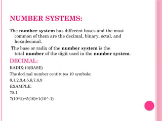
NUMBER SYSTEMS:
The numbersystem has different bases and the most
common of them are the decimal, binary, octal, and
hexadecimal.
The base or radix of the number system is the
total number of the digit used in the number system.
DECIMAL:
RADIX:10(BASE)
The decimal number contitutes 10 symbols:
0,1,2,3,4,5,6,7,8,9
EXAMPLE:
75.1
7(10^2)+5(10)+1(10^-1)
5.
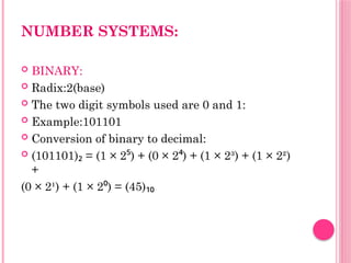
NUMBER SYSTEMS:
BINARY:
Radix:2(base)
The two digit symbols used are 0 and 1:
Example:101101
Conversion of binary to decimal:
(101101) = (1 × 2 ) + (0 × 2 ) + (1 × 2³) + (1 × 2²)
₂ ⁵ ⁴
+
(0 × 2¹) + (1 × 2 ) = (45)
⁰ ₁₀
6.
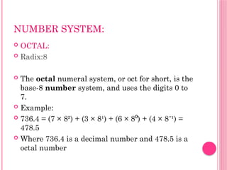
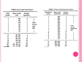
NUMBER SYSTEM:
OCTAL:
Radix:8
The octal numeral system, or oct for short, is the
base-8 number system, and uses the digits 0 to
7.
Example:
736.4 = (7 × 8²) + (3 × 8¹) + (6 × 8 ) + (4 × 8 ¹) =
⁰ ⁻
478.5
Where 736.4 is a decimal number and 478.5 is a
octal number
7.
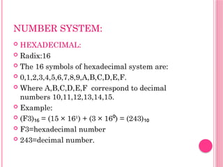
NUMBER SYSTEM:
HEXADECIMAL:
Radix:16
The 16 symbols of hexadecimal system are:
0,1,2,3,4,5,6,7,8,9,A,B,C,D,E,F.
Where A,B,C,D,E,F correspond to decimal
numbers 10,11,12,13,14,15.
Example:
(F3) = (15 × 16¹) + (3 × 16 ) = (243)
₁₆ ⁰ ₁₀
F3=hexadecimal number
243=decimal number.
8.
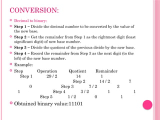
CONVERSION:
Decimal tobinary:
Step 1 − Divide the decimal number to be converted by the value of
the new base.
Step 2 − Get the remainder from Step 1 as the rightmost digit (least
significant digit) of new base number.
Step 3 − Divide the quotient of the previous divide by the new base.
Step 4 − Record the remainder from Step 3 as the next digit (to the
left) of the new base number.
Example:
Step Operation Quotient Remainder
Step 1 29 / 2 14 1
Step 2 14 / 2 7
0 Step 3 7 / 2 3
1 Step 4 3 / 2 1 1
Step 5 1 / 2 0 1
Obtained binary value:11101
9.
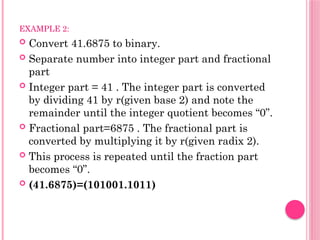
EXAMPLE 2:
Convert41.6875 to binary.
Separate number into integer part and fractional
part
Integer part = 41 . The integer part is converted
by dividing 41 by r(given base 2) and note the
remainder until the integer quotient becomes “0”.
Fractional part=6875 . The fractional part is
converted by multiplying it by r(given radix 2).
This process is repeated until the fraction part
becomes “0”.
(41.6875)=(101001.1011)
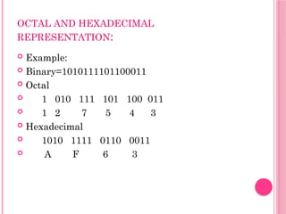
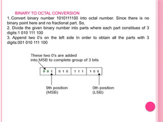
BINARY TO OCTALCONVERSION
1. Convert binary number 1010111100 into octal number. Since there is no
binary point here and no fractional part. So,
2. Divide the given binary number into parts where each part constitues of 3
digits:1 010 111 100
3. Append two 0’s on the left side In order to obtain all the parts with 3
digits:001 010 111 100
13.
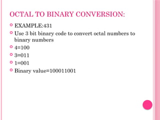
OCTAL TO BINARYCONVERSION:
EXAMPLE:431
Use 3 bit binary code to convert octal numbers to
binary numbers
4=100
3=011
1=001
Binary value=100011001
14.
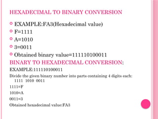
HEXADECIMAL TO BINARYCONVERSION
EXAMPLE:FA3(Hexadecimal value)
F=1111
A=1010
3=0011
Obtained binary value=111110100011
BINARY TO HEXADECIMAL CONVERSION:
EXAMPLE:111110100011
Divide the given binary number into parts containing 4 digits each:
1111 1010 0011
1111=F
1010=A
0011=3
Obtained hexadecimal value:FA3
15.
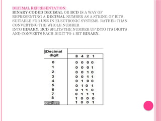
DECIMAL REPRESENTATION:
BINARY-CODED DECIMALOR BCD IS A WAY OF
REPRESENTING A DECIMAL NUMBER AS A STRING OF BITS
SUITABLE FOR USE IN ELECTRONIC SYSTEMS. RATHER THAN
CONVERTING THE WHOLE NUMBER
INTO BINARY, BCD SPLITS THE NUMBER UP INTO ITS DIGITS
AND CONVERTS EACH DIGIT TO 4-BIT BINARY.
16.
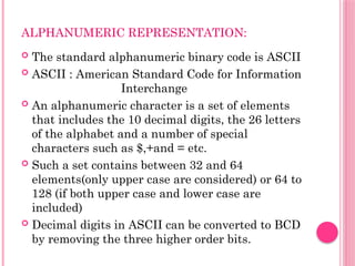
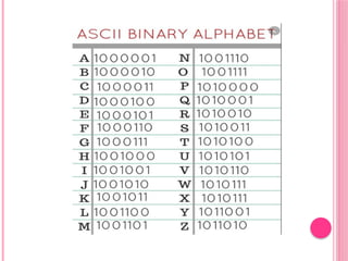
ALPHANUMERIC REPRESENTATION:
Thestandard alphanumeric binary code is ASCII
ASCII : American Standard Code for Information
Interchange
An alphanumeric character is a set of elements
that includes the 10 decimal digits, the 26 letters
of the alphabet and a number of special
characters such as $,+and = etc.
Such a set contains between 32 and 64
elements(only upper case are considered) or 64 to
128 (if both upper case and lower case are
included)
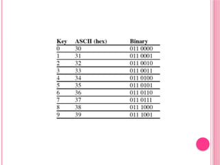
Decimal digits in ASCII can be converted to BCD
by removing the three higher order bits.
19.
2.COMPLEMENTS:
Complements areused in the digital computers in order to
simplify the subtraction operation and for the logical
manipulations. For each radix-r system (radix r represents
base of number system) there are two types of
complements.
We have 2 types of complements
1.r’s complement
2.(r-1)’s complement
For decimal numbers : complements are 10’s complement
and 9’s complement as the base of decimal numbers is 10
In the same way binary numbers have 2’s complement and
1’s complement
20.
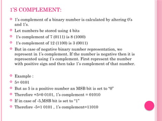
1’S COMPLEMENT:
1’scomplement of a binary number is calculated by altering 0’s
and 1’s.
Let numbers be stored using 4 bits
1's complement of 7 (0111) is 8 (1000)
1's complement of 12 (1100) is 3 (0011)
But in case of negative binary number representation, we
represent in 1’s complement. If the number is negative then it is
represented using 1’s complement. First represent the number
with positive sign and then take 1’s complement of that number.
Example :
5= 0101
But as 5 is a positive number an MSB bit is set to “0”
Therefore +5=0 0101, 1’s complement = 01010
If in case of -5,MSB bit is set to “1”
Therefore -5=1 0101 , 1’s complement=11010
21.
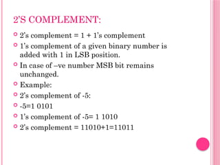
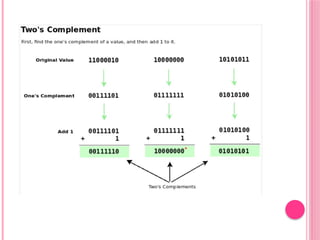
2’S COMPLEMENT:
2’scomplement = 1 + 1’s complement
1’s complement of a given binary number is
added with 1 in LSB position.
In case of –ve number MSB bit remains
unchanged.
Example:
2’s complement of -5:
-5=1 0101
1’s complement of -5= 1 1010
2’s complement = 11010+1=11011
23.
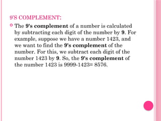
9’S COMPLEMENT:
The9's complement of a number is calculated
by subtracting each digit of the number by 9. For
example, suppose we have a number 1423, and
we want to find the 9's complement of the
number. For this, we subtract each digit of the
number 1423 by 9. So, the 9's complement of
the number 1423 is 9999-1423= 8576.
24.
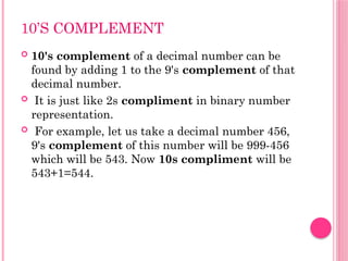
10’S COMPLEMENT
10'scomplement of a decimal number can be
found by adding 1 to the 9's complement of that
decimal number.
It is just like 2s compliment in binary number
representation.
For example, let us take a decimal number 456,
9's complement of this number will be 999-456
which will be 543. Now 10s compliment will be
543+1=544.
25.
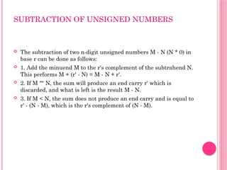
SUBTRACTION OF UNSIGNEDNUMBERS
The subtraction of two n-digit unsigned numbers M - N (N * 0) in
base r can be done as follows:
1. Add the minuend M to the r's complement of the subtrahend N.
This performs M + (r' - N) = M - N + r'.
2. If M "" N, the sum will produce an end carry r' which is
discarded, and what is left is the result M - N.
3. If M < N, the sum does not produce an end carry and is equal to
r' - (N - M), which is the r's complement of (N - M).
27.
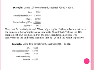
Note that Mhas 5 digits and N has only 4 digits. Both numbers must have
the same number of digits; so we can write N as 03250. Taking the 10’s
complement of N pro
duces a 9 in the most significant position. The
occurrence of the end carry signifies that M - N and the result is positive.
28.
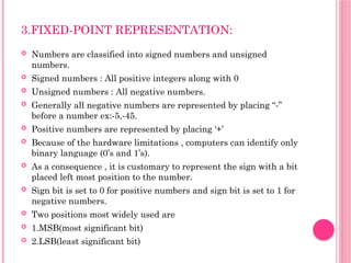
3.FIXED-POINT REPRESENTATION:
Numbersare classified into signed numbers and unsigned
numbers.
Signed numbers : All positive integers along with 0
Unsigned numbers : All negative numbers.
Generally all negative numbers are represented by placing “-”
before a number ex:-5,-45.
Positive numbers are represented by placing ‘+’
Because of the hardware limitations , computers can identify only
binary language (0’s and 1’s).
As a consequence , it is customary to represent the sign with a bit
placed left most position to the number.
Sign bit is set to 0 for positive numbers and sign bit is set to 1 for
negative numbers.
Two positions most widely used are
1.MSB(most significant bit)
2.LSB(least significant bit)
29.
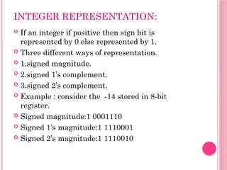
INTEGER REPRESENTATION:
Ifan integer if positive then sign bit is
represented by 0 else represented by 1.
Three different ways of representation.
1.signed magnitude.
2.signed 1’s complement.
3.signed 2’s complement.
Example : consider the -14 stored in 8-bit
register.
Signed magnitude:1 0001110
Signed 1’s magnitude:1 1110001
Signed 2’s magnitude:1 1110010
30.
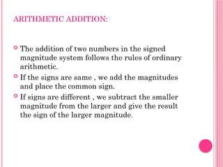
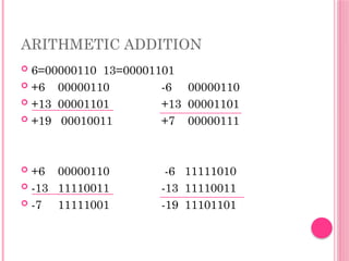
ARITHMETIC ADDITION:
Theaddition of two numbers in the signed
magnitude system follows the rules of ordinary
arithmetic.
If the signs are same , we add the magnitudes
and place the common sign.
If signs are different , we subtract the smaller
magnitude from the larger and give the result
the sign of the larger magnitude.
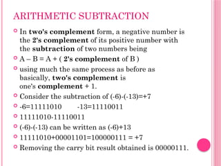
ARITHMETIC SUBTRACTION
Intwo's complement form, a negative number is
the 2's complement of its positive number with
the subtraction of two numbers being
A – B = A + ( 2's complement of B )
using much the same process as before as
basically, two's complement is
one's complement + 1.
Consider the subtraction of (-6)-(-13)=+7
-6=11111010 -13=11110011
11111010-11110011
(-6)-(-13) can be written as (-6)+13
11111010+00001101=100000111 = +7
Removing the carry bit result obtained is 00000111.
33.
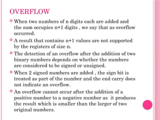
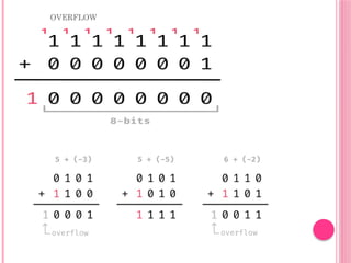
OVERFLOW
When twonumbers of n digits each are added and
the sum occupies n+1 digits , we say that as overflow
occurred.
A result that contains n+1 values are not supported
by the registers of size n.
The detection of an overflow after the addition of two
binary numbers depends on whether the numbers
are considered to be signed or unsigned.
When 2 signed numbers are added , the sign bit is
treated as part of the number and the end carry does
not indicate an overflow.
An overflow cannot occur after the addition of a
positive number to a negative number as it produces
the result which is smaller than the larger of two
original numbers.
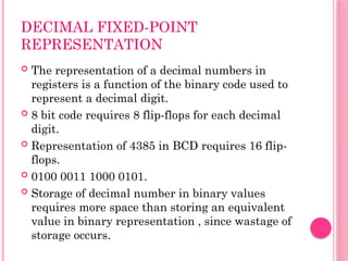
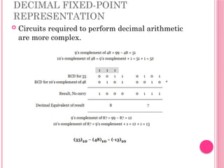
DECIMAL FIXED-POINT
REPRESENTATION
Therepresentation of a decimal numbers in
registers is a function of the binary code used to
represent a decimal digit.
8 bit code requires 8 flip-flops for each decimal
digit.
Representation of 4385 in BCD requires 16 flip-
flops.
0100 0011 1000 0101.
Storage of decimal number in binary values
requires more space than storing an equivalent
value in binary representation , since wastage of
storage occurs.
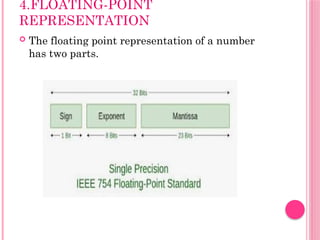
FLOATING POINT
REPRESENTATION
Thenumber 350 is normalized but 000350 is not
The number is said to be normalized only if
leftmost digit is nonzero.
Example:00011010 is not normalized because of
3 leading 0’s.
The number can be normalized by discarding the
3 leading 0’s by obtaining 11010000
Normalized numbers provide the maximum
possible precission for floating point numbers.
40.
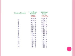
5.OTHER BINARY CODES
1.Gray code:
Gray code – also known as Cyclic Code,
Reflected Binary Code (RBC), Reflected
Binary (RB) .
Grey code – is defined as an ordering of the
binary number system such that each
incremental value can only differ by one bit.
In gray code, while traversing from one step to
another step only one bit in the code group
changes.
That is to say that two adjacent code numbers
differ from each other by only one bit.
42.
GRAY CODE
Graycode counters are sometimes used to
provide the timing sequences that control the
operations in a digital system
Gray code counters remove ambiguity during the
change from one state to other state of the
counter because only one bit can change during
the state transition.
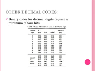
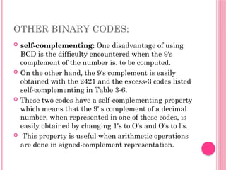
OTHER BINARY CODES:
self-complementing: One disadvantage of using
BCD is the difficulty encountered when the 9's
complement of the number is. to be computed.
On the other hand, the 9's complement is easily
obtained with the 2421 and the excess-3 codes listed
self-complementing in Table 3-6.
These two codes have a self-complementing property
which means that the 9' s complement of a decimal
number, when represented in one of these codes, is
easily obtained by changing 1's to O's and O's to l's.
This property is useful when arithmetic operations
are done in signed-complement representation.
45.
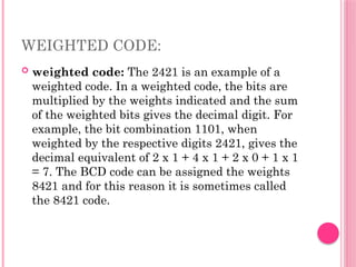
WEIGHTED CODE:
weightedcode: The 2421 is an example of a
weighted code. In a weighted code, the bits are
multiplied by the weights indicated and the sum
of the weighted bits gives the decimal digit. For
example, the bit combination 1101, when
weighted by the respective digits 2421, gives the
decimal equivalent of 2 x 1 + 4 x 1 + 2 x 0 + 1 x 1
= 7. The BCD code can be assigned the weights
8421 and for this reason it is sometimes called
the 8421 code.
46.
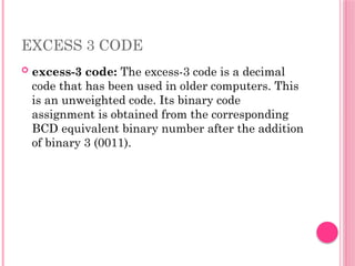
EXCESS 3 CODE
excess-3 code: The excess-3 code is a decimal
code that has been used in older computers. This
is an unweighted code. Its binary code
assignment is obtained from the corresponding
BCD equivalent binary number after the addition
of binary 3 (0011).
47.
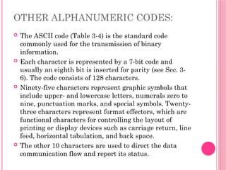
OTHER ALPHANUMERIC CODES:
The ASCII code (Table 3-4) is the standard code
commonly used for the transmission of binary
information.
Each character is represented by a 7-bit code and
usually an eighth bit is inserted for parity (see Sec. 3-
6). The code consists of 128 characters.
Ninety-five characters represent graphic symbols that
include upper- and lowercase letters, numerals zero to
nine, punctuation marks, and special symbols. Twenty-
three characters represent format effectors, which are
functional characters for controlling the layout of
printing or display devices such as carriage return, line
feed, horizontal tabulation, and back space.
The other 10 characters are used to direct the data
communication flow and report its status.
48.
EBCDIC
EBCDIC: Anotheralphanumeric (sometimes
called alphameric) code used in IBM equipment
is the EBCDIC (Extended BCD Interchange
Code). It uses eight bits for each character (and a
ninth bit for parity). EBCDIC has the same
character symbols as ASCII but the bit
assignment to characters is different.
49.
6.ERROR DETECTION CODES:
Binary information transmitted through some form
of communication medium is subject to external
noise that could change bits from 1 to 0, and vice
versa. An error detection code is a binary code that
detects digital errors during transmission.
The detected errors cannot be corrected but their
presence is indicated.
The usual procedure is to observe the frequency of
errors.
If errors occur infrequently at random, the
particular erroneous information is transmitted
again. If the error occurs too often, the system is
checked for malfunction.
50.
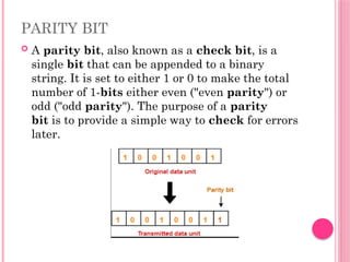
PARITY BIT
Aparity bit, also known as a check bit, is a
single bit that can be appended to a binary
string. It is set to either 1 or 0 to make the total
number of 1-bits either even ("even parity") or
odd ("odd parity"). The purpose of a parity
bit is to provide a simple way to check for errors
later.
51.
PARITY GENERATOR
Aparity generator is a combinational logic
circuit that generates the parity bit in the
transmitter. On the other hand, a circuit that
checks the parity in the receiver is
called parity checker.
52.
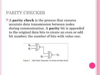
PARITY CHECKER
Aparity check is the process that ensures
accurate data transmission between nodes
during communication. A parity bit is appended
to the original data bits to create an even or odd
bit number; the number of bits with value one.