Computer Organization andArchitecture
Sri Sathya Sai University for Human Excellence
Navanihal, Okali Post, Kamalapur,
Kalaburagi, Karnataka - 585313, India
https://sssuhe.ac.in
December 11, 2025
Presentation December 11, 2025 1 / 22
Pipelining: Basic Concept
Pipeliningis a technique that decomposes a sequential task into a series of
suboperations.
Each suboperation is handled in a separate pipeline segment that works concurrently
with others.
Binary information flows through these segments, just like items moving on an assembly
line.
Each segment performs part of the computation and passes the result to the next segment.
Because segments operate simultaneously, many computations can proceed in parallel.
A register is placed between segments to isolate their operations and allow concurrency.
Presentation December 11, 2025 3 / 22
4.
Pipeline Segment Structure
Eachpipeline segment can be viewed as:
an input register, and
a combinational circuit that performs the suboperation.
The output of the combinational circuit feeds the input register of the next segment.
A common clock drives all registers.
After each clock pulse:
every segment receives new data,
every segment executes its suboperation,
the result flows to the next stage.
Thus, data moves one stage forward per clock cycle.
Presentation December 11, 2025 4 / 22
5.
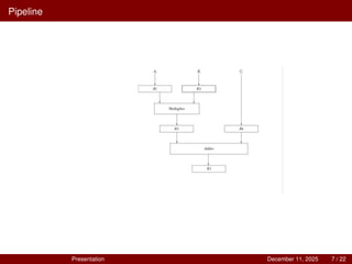
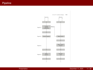
Example: Multiply-Add Pipeline
Task:
Ai×Bi +Ci for i = 1,2,3,...,7
Pipeline stages use:
Registers R1 through R5,
A multiplier (combinational circuit),
An adder (combinational circuit).
Suboperations in each pipeline segment:
1 Input Stage
R1 ← Ai , R2 ← Bi
2 Multiply Stage
R3 ← R1 ×R2, R4 ← Ci
3 Add Stage
R5 ← R3 +R4
Presentation December 11, 2025 5 / 22
6.
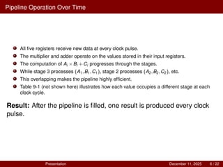
Pipeline Operation OverTime
All five registers receive new data at every clock pulse.
The multiplier and adder operate on the values stored in their input registers.
The computation of Ai ×Bi +Ci progresses through the stages.
While stage 3 processes (A1,B1,C1), stage 2 processes (A2,B2,C2), etc.
This overlapping makes the pipeline highly efficient.
Table 9-1 (not shown here) illustrates how each value occupies a different stage at each
clock cycle.
Result: After the pipeline is filled, one result is produced every clock
pulse.
Presentation December 11, 2025 6 / 22
Arithmetic Pipelines: Introduction
Anarithmetic pipeline accelerates arithmetic operations by dividing them into smaller
stages.
Each stage performs a specific suboperation and works concurrently with other stages.
Pipelining improves the overall performance and throughput of the system.
It is commonly used for floating–point addition and subtraction.
Modern processors and floating–point units use arithmetic pipelines to complete one result
per clock cycle after the pipeline is filled.
Presentation December 11, 2025 8 / 22
9.
Pipeline Structure forFloating-Point Operations
A floating–point pipeline generally includes stages such as:
exponent comparison and difference calculation,
alignment of mantissas,
addition or subtraction of aligned values,
normalization of the result,
rounding and formatting.
Each stage operates in parallel on different data items.
This structure increases efficiency similar to an assembly-line process.
Arithmetic pipelines allow new operands to enter before previous results are fully
completed.
Presentation December 11, 2025 9 / 22
10.
Advantages and Applicationsof Arithmetic Pipelines
Advantages:
Higher computational speed,
Increased throughput,
Efficient utilization of hardware resources.
Applications:
scientific and engineering calculations,
real-time graphics and image processing,
simulation and modeling tasks,
deep learning accelerators and tensor processors.
Pipelining is fundamental to modern CPU and GPU architectures.
Presentation December 11, 2025 10 / 22
Instruction Pipeline: Introduction
Aninstruction pipeline increases CPU performance by dividing instruction execution into
multiple stages.
A program consists of many instructions; pipelining allows several instructions to be
processed at the same time.
Each stage of the pipeline handles a different part of the instruction.
The aim is to improve throughput, meaning more instructions completed per unit time.
Presentation December 11, 2025 12 / 22
13.
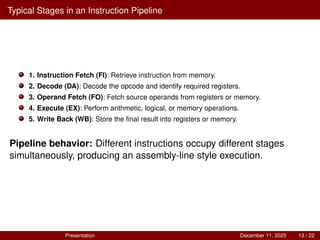
Typical Stages inan Instruction Pipeline
1. Instruction Fetch (FI): Retrieve instruction from memory.
2. Decode (DA): Decode the opcode and identify required registers.
3. Operand Fetch (FO): Fetch source operands from registers or memory.
4. Execute (EX): Perform arithmetic, logical, or memory operations.
5. Write Back (WB): Store the final result into registers or memory.
Pipeline behavior: Different instructions occupy different stages
simultaneously, producing an assembly-line style execution.
Presentation December 11, 2025 13 / 22
14.
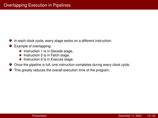
Overlapping Execution inPipelines
In each clock cycle, every stage works on a different instruction.
Example of overlapping:
Instruction 1 is in Decode stage,
Instruction 2 is in Fetch stage,
Instruction 0 is in Execute stage.
Once the pipeline is full, one instruction completes during every clock cycle.
This greatly reduces the overall execution time of the program.
Presentation December 11, 2025 14 / 22
15.
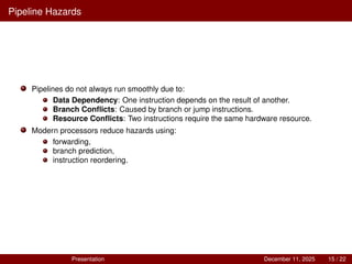
Pipeline Hazards
Pipelines donot always run smoothly due to:
Data Dependency: One instruction depends on the result of another.
Branch Conflicts: Caused by branch or jump instructions.
Resource Conflicts: Two instructions require the same hardware resource.
Modern processors reduce hazards using:
forwarding,
branch prediction,
instruction reordering.
Presentation December 11, 2025 15 / 22
16.
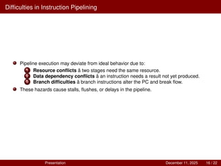
Difficulties in InstructionPipelining
Pipeline execution may deviate from ideal behavior due to:
1 Resource conflicts â two stages need the same resource.
2 Data dependency conflicts â an instruction needs a result not yet produced.
3 Branch difficulties â branch instructions alter the PC and break flow.
These hazards cause stalls, flushes, or delays in the pipeline.
Presentation December 11, 2025 16 / 22
17.
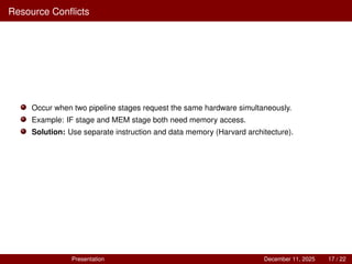
Resource Conflicts
Occur whentwo pipeline stages request the same hardware simultaneously.
Example: IF stage and MEM stage both need memory access.
Solution: Use separate instruction and data memory (Harvard architecture).
Presentation December 11, 2025 17 / 22
18.
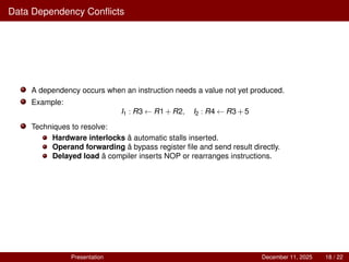
Data Dependency Conflicts
Adependency occurs when an instruction needs a value not yet produced.
Example:
I1 : R3 ← R1+R2, I2 : R4 ← R3+5
Techniques to resolve:
Hardware interlocks â automatic stalls inserted.
Operand forwarding â bypass register file and send result directly.
Delayed load â compiler inserts NOP or rearranges instructions.
Presentation December 11, 2025 18 / 22
19.
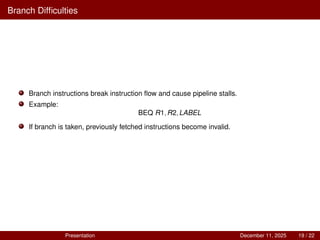
Branch Difficulties
Branch instructionsbreak instruction flow and cause pipeline stalls.
Example:
BEQ R1,R2,LABEL
If branch is taken, previously fetched instructions become invalid.
Presentation December 11, 2025 19 / 22
20.
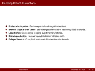
Handling Branch Instructions
Prefetchboth paths: Fetch sequential and target instructions.
Branch Target Buffer (BTB): Stores target addresses of frequently used branches.
Loop buffer: Stores entire loops to avoid memory fetches.
Branch prediction: Hardware predicts taken/not taken path.
Delayed branch: Compiler inserts useful instruction after branch.
Presentation December 11, 2025 20 / 22
21.
Pipeline Exercises (Problems9-1 to 9-4)
9-1. In certain scientific computations it is necessary to perform the arithmetic operation
(Ai Bi )(Ci Di )
with a stream of numbers. Specify a pipeline configuration to carry out this task. List the
contents of all registers in the pipeline for i = 1 through 6.
9-2. Draw a space–time diagram for a six-segment pipeline showing the time it takes to
process eight tasks.
9-3. Determine the number of clock cycles that it takes to process 200 tasks in a six-segment
pipeline.
9-4. A nonpipeline system takes 50ns to process a task. The same task can be processed in a
six-segment pipeline with a clock cycle of 10ns. Determine the speedup ratio of the
pipeline for 100 tasks. What is the maximum speedup that can be achieved?
Presentation December 11, 2025 21 / 22
22.
Pipeline Exercise (Problem9-5)
9-5. The pipeline of Fig. 9-2 has the following propagation times:
40ns for the operands to be read from memory into registers R1 and R2,
45ns for the signal to propagate through the multiplier,
5ns for the transfer into R3,
15ns to add the two numbers into R5.
(a) What is the minimum clock cycle time that can be used?
(b) A nonpipeline system can perform the same operation by removing R3 and R4. How
long will it take to multiply and add the operands without using the pipeline?
(c) Calculate the speedup of the pipeline for 10 tasks and again for 100 tasks.
(d) What is the maximum speedup that can be achieved?
Presentation December 11, 2025 22 / 22