Downloaded 69 times

![[3]
[3,1,8,11]
1
2
4
5
6 7
8
9
10
11
3 (S)
11 (D)
[3,1]
[3,1,6]
[3,1,8]
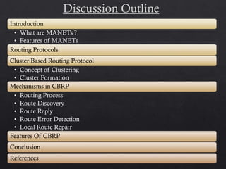
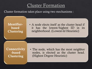
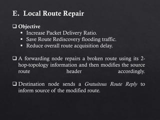
Example :
Source Node-[3]
Destination Node-[11]
Route Discovered- [3,1,8,11]](https://image.slidesharecdn.com/clusterbasedroutingprotocol-1-140412113855-phpapp02/85/Cluster-based-routing-protocol-1-11-320.jpg)
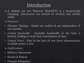
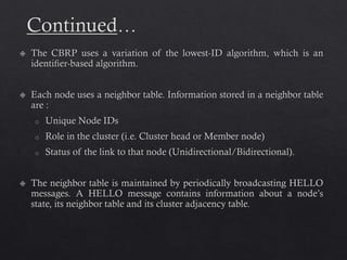
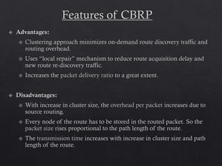
![C. Route Reply
If the RREQ reaches the destination node ‘D’, it contains
the path called as “loose source route”, [S,C1,C2,...,Ck,D].
‘D’ sends a Route Reply message (RREP) back to S using
the reversed loose source route [D, Ck,...,C1,S], i.e. RREP
is sent back to source along reversed loose source route of
cluster heads.
Every time a cluster head receives this RREP it computes
a strict source route, which then consists only of nodes that
form the shortest path within each cluster.](https://image.slidesharecdn.com/clusterbasedroutingprotocol-1-140412113855-phpapp02/85/Cluster-based-routing-protocol-1-12-320.jpg)
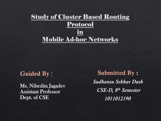
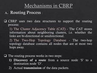
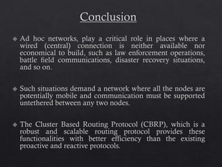
![Example :
Source Node-[3]
Destination Node-[11]
Loose Source Route of
RREP- [11,8,1,3]
Strict Source Route of
RREP- [11,9,4,3]
1
2
4
5 6
7
8
9
10
3
11
3 (S)
11 (D)
[11][11,9]
[11,9,4]
[11,9,4,3]](https://image.slidesharecdn.com/clusterbasedroutingprotocol-1-140412113855-phpapp02/85/Cluster-based-routing-protocol-1-13-320.jpg)
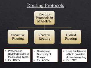
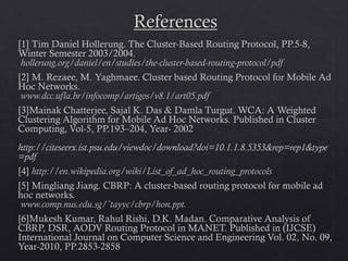
![Example :
Source Node-[3]
Destination Node-[11]
Loose Source Route of
RREP- [11,8,1,3]
Strict Source Route of
RREP- [11,9,4,3]
1
2
4
5 6
7
8
9
10
3
11
3 (S)
11 (D)](https://image.slidesharecdn.com/clusterbasedroutingprotocol-1-140412113855-phpapp02/85/Cluster-based-routing-protocol-1-14-320.jpg)
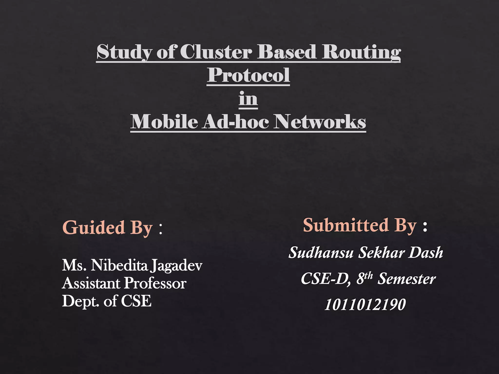
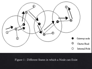
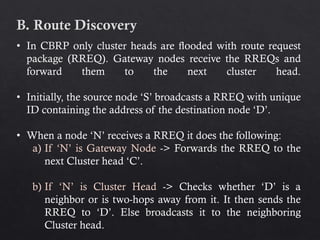
![D. Route Error Detection
After determining the route, source routing is used for actual
packet transmission.
A forwarding node sends a Route Error Message (ERR) to
packet source if the next hop in source route is unreachable.
1
2
4
5 6
7
8
9
10
3
11
3 (S)
11 (D)
Example:
Source route header of data
packet: [3,4,9,11]
Route error (ERR)
down link: [9->11]](https://image.slidesharecdn.com/clusterbasedroutingprotocol-1-140412113855-phpapp02/85/Cluster-based-routing-protocol-1-15-320.jpg)
![1
2
4
5 6
7
8
9
10
3
11
3 (S)
11 (D)
Example :
Source route header of Data
Packet : [3,4,9,11]
Route error (ERR)
down link : [9->11]](https://image.slidesharecdn.com/clusterbasedroutingprotocol-1-140412113855-phpapp02/85/Cluster-based-routing-protocol-1-17-320.jpg)
![1
2
4
5 6
7
8
9
10
3
11
3 (S)
11 (D)
Example :
Source route header of Data
Packet : [3,4,9,11]
Modified source route:
[3,4,9,8,11]](https://image.slidesharecdn.com/clusterbasedroutingprotocol-1-140412113855-phpapp02/85/Cluster-based-routing-protocol-1-18-320.jpg)
![1
2
4
5 6
7
8
9
10
3
11
3 (S)
11 (D)
Example :
Source route header of Data
Packet : [3,4,9,11]
Gratuitous route reply :
[3,4,9,8,11]](https://image.slidesharecdn.com/clusterbasedroutingprotocol-1-140412113855-phpapp02/85/Cluster-based-routing-protocol-1-19-320.jpg)


This document summarizes the Cluster Based Routing Protocol (CBRP) for mobile ad hoc networks. CBRP uses clustering to divide the network into sub-structures called clusters, each with a cluster head that communicates routing information between nodes. It discovers routes through route requests broadcast only to cluster heads, and maintains routing tables and two-hop topology databases to support routing. When a link fails, local route repair is performed using topology information before route rediscovery is initiated.