The document outlines the practices of requirements engineering (RE) and emphasizes the importance of adapting documentation to the project context by selecting appropriate work products. It discusses various types of work products used in RE, their characteristics, abstraction levels, levels of detail, and key aspects to consider during specification, including functional and quality requirements. Additionally, the document provides guidelines for effective documentation and highlights the need for consistency and clarity in requirements representation.
![Handbook IREB CPRE Foundation Level - Version 1.1.0 Page 28 / 143
3 Work Products and Documentation Practices
Traditional Requirements Engineering (RE) calls for the writing of a comprehensive,
complete, and unambiguous requirements specification [IEEE830], [Glin2016]. While
it is still appropriate to create fully-fledged requirements specifications in many
cases, there are also many other cases where the cost of writing such specifications
exceeds their benefit. For example, fully-fledged requirements specifications are
useful or even necessary when tendering or outsourcing the design and
implementation of a system or when a system is safety-critical and regulatory
compliance is required. On the other hand, where stakeholders and developers join
forces to define and develop a system iteratively, writing a comprehensive
requirements specification does not make sense. It is therefore vital in RE to adapt
the documentation to the project context and to select work products for
documenting requirements and requirements-related information that yield optimal
value for the project.
In this chapter, you will learn about the typical RE work products and how to create
them.
3.1 Work Products in Requirements Engineering
There are a variety of work products that are used in RE.
Definition 3.1. Work product: A recorded intermediate or final result generated in a
work process.
We consider the term artifact as a synonym for work product. We prefer the term
work product over artifact to express the connotation that a work product is the
result of work performed in a work process.
According to this definition, an RE work product can be anything that expresses
requirements, from a single sentence or diagram to a system requirements
specification that covers hundreds of pages. It is also important to note that a work
product may contain other work products.
3.1.1 Characteristics of Work Products
Work products can be characterized by the following facets: purpose, size,
representation, lifespan, and storage.
Table 3.1 gives an overview of typical work products used in RE along with their
respective purpose (that is, what the work product specifies or provides) and typical
size. The table is structured into four groups: work products for single requirements,
coherent sets of requirements, documents or documentation structures, and other
work products.
There are many different ways to represent a work product. In RE, representations
based on natural language, templates, and models are of particular importance. These
are discussed in Sections 3.2, 3.3, and 3.4, respectively. There are further
representations, such as drawings or prototypes, which are covered in Section 3.7.
Every work product has a lifespan. This is the period of time from the creation of the
work product until the point where the work product is discarded or becomes
irrelevant. We distinguish between three categories of work products with respect to
lifespan: temporary, evolving, and durable work products.
Work product
Artifact
Characterization of
work products
Representation
Lifespan](https://image.slidesharecdn.com/chapter3cprefoundationlevelhandbookgeneral-241003184941-f97fe9b6/85/Chapter_3_CPRE_FoundationLevel_Handbook_General-pdf-1-320.jpg)

![Handbook IREB CPRE Foundation Level - Version 1.1.0 Page 31 / 143
3.1.3 Level of Detail
When specifying requirements, Requirements Engineers have to decide on the level
of detail in which the requirements shall be specified. However, deciding which level
of detail is appropriate or even optimal for a given requirement is a challenging task.
For example, in a situation where the customer and the supplier of a system
collaborate closely, it might be sufficient to state a requirement about a data entry
form as follows: “The system shall provide a form for entering the personal data of
the customer.” In contrast, in a situation where the design and implementation of the
system are outsourced to a supplier with little or no domain knowledge, a detailed
specification of the customer entry form will be necessary.
The level of detail to which requirements should be specified depends on several
factors, in particular:
The problem and project context: the harder the problem and the less
familiar the Requirements Engineers and developers are with the project
context, the more detail is necessary.
The degree of shared understanding of the problem: when there is low
implicit shared understanding (see Principle 3 in Chapter 2), explicit,
detailed specifications are required to create the necessary degree of shared
understanding.
The degree of freedom left to designers and programmers: less detailed
requirements give the developers more freedom.
Availability of rapid stakeholder feedback during design and
implementation: when rapid feedback is available, less detailed
specifications suffice to control the risk of developing the wrong system.
Cost vs. value of a detailed specification: the higher the benefit of a
requirement, the more we can afford to specify it in detail.
Standards and regulations: Standards imposed and regulatory constraints
may mean that requirements have to be specified in more detail than would
otherwise be necessary.
There is no universally “right” level of detail for requirements. For every requirement,
the adequate level of detail depends on many factors. The greater the level of detail in
the requirements specified, the lower the risk of eventually getting something that
has unexpected or missing features or properties. However, the cost for the
specification increases as the level of detail increases.
3.1.4 Aspects to be Considered
Regardless of the RE work products being used, several aspects need to be considered
when specifying requirements [Glin2019].
First, as there are functional requirements, quality requirements, and constraints (see
Section 1.1), Requirements Engineers have to make sure that they cover all three
kinds of requirements when documenting requirements. In practice, stakeholders
tend to omit quality requirements because they take them for granted.
They also tend to specify constraints as functional requirements. It is therefore
important that the Requirements Engineers get this right.
How much detail?
Factors affecting the
level of detail needed
Considering multiple
aspects](https://image.slidesharecdn.com/chapter3cprefoundationlevelhandbookgeneral-241003184941-f97fe9b6/85/Chapter_3_CPRE_FoundationLevel_Handbook_General-pdf-4-320.jpg)
![Handbook IREB CPRE Foundation Level - Version 1.1.0 Page 32 / 143
When looking at functional requirements, we observe that they pertain to different
aspects, as, for example, a required data structure, a required order of actions, or the
required reaction to some external event. We distinguish between three major
aspects: structure and data, function and flow, and state and behavior.
The structure and data aspect focuses on requirements concerning the static
structure of a system and the (persistent) data that a system must know in order to
perform the required functions and deliver the required results.
The function and flow aspect deals with the functions that a system shall provide and
the flow of control and data within and between functions for creating the required
results from given inputs.
The state and behavior aspect concentrates on specifying the state-dependent
behavior of a system—in particular, how a system shall react to which external event
depending on the system’s current state.
When dealing with quality requirements, such as usability, reliability, or availability, a
quality model—for example, the model provided by ISO/IEC 25010 [ISO25010]—can
be used as a checklist.
Within the quality requirements, performance requirements are of particular
importance. Performance requirements deal with:
Time (e.g., for performing a task or reacting to external events)
Volume (e.g., required database size)
Frequency (e.g., of computing a function or receiving stimuli from sensors)
Throughput (e.g., data transmission or transaction rates)
Resource consumption (e.g., CPU, storage, bandwidth, battery)
Some people also consider the required accuracy of a computation as a performance
requirement.
Whenever possible, measurable values should be specified. When values follow a
probability distribution, specifying just the average does not suffice. If the
distribution function and its parameters cannot be specified, Requirements Engineers
should strive to specify minimum and maximum values or 95 percent values in
addition to the averages.
Documenting quality requirements beyond performance requirements is notoriously
difficult.
Qualitative representations, such as “The system shall be secure and easy to use,” are
ambiguous and thus difficult to achieve and validate.
Quantitative representations are measurable, which is a big asset in terms of
systematically achieving and validating a quality requirement. However, they raise
principal difficulties (for example, how can we state security in quantitative terms?)
and can be quite expensive to specify.
Operationalized representations state a quality requirement in terms of functional
requirements for achieving the desired quality. For example, a data security
requirement may be expressed in terms of a login function that restricts the access to
the data and a function that encrypts the stored data. Operationalized representations
make quality requirements testable but may also imply premature design decisions.
The often-heard rule “Only a quantified quality requirement is a good quality
requirement” is outdated and may lead to quality requirements having low or even
negative value due to the high effort involved in the quantification. Instead, a risk-
based approach should be used [Glin2008].
Aspects within the
functional requirements
Structure and data
Function and flow
State and behavior
Quality requirements
Difficulty of
documenting quality
requirements](https://image.slidesharecdn.com/chapter3cprefoundationlevelhandbookgeneral-241003184941-f97fe9b6/85/Chapter_3_CPRE_FoundationLevel_Handbook_General-pdf-5-320.jpg)

![Handbook IREB CPRE Foundation Level - Version 1.1.0 Page 36 / 143
Define and consistently use a uniform terminology. Creating and using a
glossary (Section 3.5) is the core means for avoiding misunderstandings and
inconsistencies about terminology.
Avoid using vague or ambiguous terms and phrases.
Know and avoid the pitfalls of technical writing (see below).
When writing technical documents in natural language, there are some well-known
pitfalls that should be avoided or things that need to be used with care (see, for
example, [GoRu2003]).
Requirements Engineers should avoid writing requirements that contain the
following:
Incomplete descriptions. Verbs in natural language typically come with a set
of placeholders for nouns or pronouns. For example, the verb “give” has
three placeholders for who gives what to whom. When writing a requirement
in natural language, all placeholders of the verb used should be filled.
Unspecific nouns. Using nouns such as “the data” or “the user” leaves too
much room for different interpretations by different stakeholders or
developers. They should be replaced by more specific nouns or be made
more specific by adding adjectives or assigning them a well-defined type.
Incomplete conditions. When describing what shall be done, many people
focus on the normal case, omitting exceptional cases. In technical writing,
this is a trap to avoid: when something happens only if certain conditions
are true, such conditions shall be stated, providing both then and else
clauses.
Incomplete comparisons. In spoken communication, people tend to use
comparatives (for example, “the new video app is much better”) without
saying what they are comparing to, typically assuming that this is clear from
the context. In technical writing, comparisons should include a reference
object, for example, “faster than 0.1 ms”.
There are some further things that Requirements Engineers need to use with care, as
they constitute potential pitfalls:
Passive voice. Sentences in passive voice have no acting subject. If a
requirement is stated in the passive voice, this may hide who is responsible
for the action described in the requirement, leading to an incomplete
description.
Universal quantifiers. Universal quantifiers are words such as all, always, or
never, which are used to make statements that are universally true. In
technical systems, however, such universal properties are rare. Whenever
Requirements Engineers use a universal quantifier, they need to reflect on
whether they are stating a truly universal property or whether they are
instead specifying a general rule that has exceptions (which they also need
to specify). They should apply the same caution when using “either-or”
clauses, which, by their semantics, exclude any further exceptional cases.
Uniform terminology
Vagueness, ambiguity
Knowing the pitfalls
Things to avoid
Incomplete descriptions
Unspecific nouns
Incomplete conditions
Incomplete comparisons
Things to handle with
care
Passive voice
Universal quantifiers](https://image.slidesharecdn.com/chapter3cprefoundationlevelhandbookgeneral-241003184941-f97fe9b6/85/Chapter_3_CPRE_FoundationLevel_Handbook_General-pdf-9-320.jpg)
![Handbook IREB CPRE Foundation Level - Version 1.1.0 Page 37 / 143
Nominalizations. When a noun is derived from a verb (for example,
“authentication” from “to authenticate”), linguists call this a nominalization.
When specifying requirements, Requirements Engineers need to handle
nominalizations with care because a nominalization may hide unspecified
requirements. For example, the requirement “Only after successful
authentication, the system shall provide a user access to (…)” implies that a
procedure for authenticating users exists. When writing such a requirement,
therefore, the Requirements Engineer must check whether there are also
requirements about the procedure for authenticating legitimate users.
Natural language is a very powerful means for writing requirements. To mitigate the
inherent disadvantages of using natural language for technical documentation,
Requirements Engineers should follow proven writing rules and avoid well-known
pitfalls.
3.3 Template-Based Work Products
As mentioned in Section 3.2 above, using templates is a proven means for writing
good, well-structured work products in natural language and thus mitigating some of
the weaknesses of natural language for technical writing. A template is a kind of
ready-made blueprint for the syntactic structure of a work product. When using
natural language in RE, we distinguish between three classes of templates: phrase
templates, form templates, and document templates.
3.3.1 Phrase Templates
Definition 3.2. Phrase template: A template for the syntactic structure of a phrase that
expresses an individual requirement or a user story in natural language.
A phrase template provides a skeleton structure with placeholders, in which
Requirements Engineers fill in the placeholders in order to get well-structured,
uniform sentences that express the requirements.
Using phrase templates is a best practice when writing individual requirements in
natural language and when writing user stories.
3.3.1.1 Phrase Templates for Individual Requirements
Various phrase templates for writing individual requirements have been defined, for
example, in [ISO29148], [MWHN2009], and [Rupp2014]. The standard ISO/IEC/IEEE
29148 [ISO29148] provides a single, uniform template for individual requirements as
follows:
[<Condition>] <Subject> <Action> <Objects> [<Restriction>].
Nominalizations
Phrase template
ISO/IEC/IEEE 29148
phrase template](https://image.slidesharecdn.com/chapter3cprefoundationlevelhandbookgeneral-241003184941-f97fe9b6/85/Chapter_3_CPRE_FoundationLevel_Handbook_General-pdf-10-320.jpg)
![Handbook IREB CPRE Foundation Level - Version 1.1.0 Page 38 / 143
Example: When a valid card is sensed, the system shall display the “Enter your PIN”
message on the dialog screen within 200 ms.
When formulating an action with this template, the following conventions about the
use of auxiliary verbs are frequently used in practice:
Shall denotes a mandatory requirement.
Should denotes a requirement that is not mandatory but strongly desired.
May denotes a suggestion.
Will (or using a verb in the present tense without one of the auxiliary verbs
mentioned above) denotes a factual statement that is not considered as a
requirement.
When there are no agreed meanings for auxiliary verbs in a project, or when in doubt,
definitions such as the ones given above should be made part of a requirements
specification.
EARS (Easy Approach to Requirements Syntax) [MWHN2009] provides a set of
phrase templates that are adapted to different situations as described
below.Ubiquitous requirements (must always hold):
The <system name> shall <system response>.
Event-driven requirements (triggered by an external event):
WHEN <optional preconditions> <trigger> the <system name>
shall <system response>.
Unwanted behavior (describing situations to be avoided):
IF <optional preconditions> <trigger>, THEN the <system name>
shall <system response>.
Note: Although the unwanted behavior template is similar to the event-driven one,
Mavin et al. provide a separate template for the latter, arguing that unwanted
behavior (primarily due to unexpected events in the context, such as failures, attacks,
or things that nobody has thought of), is a major source of omissions in RE.
State-driven requirements (apply only in certain states):
WHILE <in a specific state> the <system name> shall <system response>.
Using auxiliary verbs
EARS templates](https://image.slidesharecdn.com/chapter3cprefoundationlevelhandbookgeneral-241003184941-f97fe9b6/85/Chapter_3_CPRE_FoundationLevel_Handbook_General-pdf-11-320.jpg)
![Handbook IREB CPRE Foundation Level - Version 1.1.0 Page 39 / 143
Optional features (applicable only if some feature is included in the system):
WHERE <feature is included> the <system name> shall <system response>.
In practice, sentences that combine the keywords WHEN, WHILE, and WHERE may
be needed to express complex requirements.
EARS has been designed primarily for the specification of cyber-physical systems.
However, it can also be adapted for other types of systems.
3.3.1.2 Phrase Templates for User Stories
The classic phrase template for writing user stories was introduced by Cohn
[Cohn2004]:
As a <role> I want <requirement> so that <benefit>.
Example: “As a line manager, I want to make ad hoc inquiries to the accounting system so
that I can do financial planning for my department.”
While Cohn has designated the <benefit> part of the template as optional, it is
standard practice nowadays to specify a benefit for every user story.
Every user story should be accompanied by a set of acceptance criteria—that is,
criteria that the implementation of the user story must satisfy in order to be accepted
by the stakeholders. Acceptance criteria make a user story more concrete and less
ambiguous. This helps to avoid implementation errors due to misunderstandings.
3.3.2 Form Templates
Definition 3.3. Form template: A template providing a form with predefined fields to
be filled in.
Form templates are used to structure work products of medium size such as use
cases. Cockburn [Cock2001] introduced a popular form template for use cases.
[Laue2002] proposed a template for task descriptions. Table 3.2 shows a simple
form template for use cases. Each flow step may be subdivided into an action by an
actor and the response by the system.
Cohn’s user story
template
Acceptance criteria
Form template](https://image.slidesharecdn.com/chapter3cprefoundationlevelhandbookgeneral-241003184941-f97fe9b6/85/Chapter_3_CPRE_FoundationLevel_Handbook_General-pdf-12-320.jpg)
![Handbook IREB CPRE Foundation Level - Version 1.1.0 Page 40 / 143
Table 3.2 A simple form template for writing use cases
Name < A short active verb phrase>
Precondition <Condition(s) that must hold when the execution of the use case is
triggered>
Success end condition <State upon successful completion of use case>
Failed end condition <State upon failed execution of use case>
Primary actor <Actor name>
Other actors <List of other actors involved, if any>
Trigger <Event that initiates the execution of the use case>
Normal flow <Description of the main success scenario in a sequence of steps:
<step 1> <action 1>
<step 2> <action 2>
...
<step n> <action n> ... >
Alternate flows <Description of alternative or exceptional steps, with references to the
corresponding steps in the normal flow>
Extensions <Extensions to the normal flow (if there are any), with references to the
extended steps in the normal flow>
Related information <Optional field for further information, such as performance, frequency,
relationship to other use cases, etc.>
Form templates are also useful for writing quality requirements in a measurable form
[Gilb1988]. Table 3.3 provides a simple form template for measurable quality
requirements, along with an example.
Table 3.3 A form template for specifying measurable quality requirements
Template Example
ID <Number of requirement> R137.2
Goal <Qualitatively stated goal> Confirm room reservations immediately
Scale <Scale for measuring the
requirement>
Elapsed time in seconds (ratio scale)
Meter <Procedure for measuring the
requirement>
Timestamping the moments when the user hits the
“Reserve” button and when the app has displayed the
confirmation. Measuring the time difference.
Minimum <Minimum acceptable quality to
be achieved>
Less than 5 s in at least 95% of all cases
OK range <Value range that is OK and is
aimed at>
Between 0.5 and 3 s in more than 98% of all cases
Desired <Quality achieved in the best
possible case>
Less than 0.5 s in 100% of all cases
3.3.3 Document Templates
Definition 3.4. Document template: A template providing a predefined skeleton
structure for a document.
Document templates help to systematically structure requirements documents—for
example, a system requirements specification. RE document templates may be found
in standards, for example in [ISO29148]. The Volere template by Robertson and
Robertson [RoRo2012], [Vole2020] is also popular in practice. When a requirements
specification is included in the set of work products that a customer has ordered and
will pay for, that customer may prescribe the use of document templates supplied by
Use case template
Measurable quality
requirement template
Document template](https://image.slidesharecdn.com/chapter3cprefoundationlevelhandbookgeneral-241003184941-f97fe9b6/85/Chapter_3_CPRE_FoundationLevel_Handbook_General-pdf-13-320.jpg)
![Handbook IREB CPRE Foundation Level - Version 1.1.0 Page 41 / 143
the customer. In Figure 3.1, we show an example of a simple document template for a
system requirements specification.
3.3.4 Advantages and Disadvantages
Using templates when writing RE work products in natural language has major
advantages. Templates provide a clear, re-usable structure for work products, make
them look uniform, and thus improve the readability of the work products. Templates
also help you to capture the most relevant information and make fewer errors of
omission. On the other hand, there is a potential pitfall when Requirements Engineers
use templates mechanically, focusing on the syntactic structure rather than on
content, neglecting everything that does not fit the template.
Part I: Introduction
1. System purpose
2. Scope of system development
3. Stakeholders
Part II: System overview
4. System vision and goals
5. System context and boundary
6. Overall system structure
7. User characteristics
Part III: System requirements
Organized hierarchically according to system structure, using a hierarchical
numbering scheme for requirements
Per subsystem/component:
• Functional requirements (structure and data, function and flow, state
and behavior)
• Quality requirements
• Constraints
• Interfaces
References
Appendices
Glossary (if not managed as a work product of its own)
Assumptions and dependencies
Figure 3.1 A simple system requirements specification template
Using templates when writing RE work products in natural language improves the
quality of the work products provided that the templates are not misused as just a
syntactic exercise.
3.4 Model-Based Work Products
Requirements formulated in natural language can easily be read by people provided
they can speak the language. Natural language suffers from ambiguity due to the
imprecision of semantics of words, phrases, and sentences [Davi1993]. This
imprecision may lead to confusion and omissions in requirements. When you read
textual requirements, you will try to interpret them in your own way. We often try to
imagine these requirements in our mind. When the number of requirements is
Sample document
template
Requirements in natural
language have their
limitations](https://image.slidesharecdn.com/chapter3cprefoundationlevelhandbookgeneral-241003184941-f97fe9b6/85/Chapter_3_CPRE_FoundationLevel_Handbook_General-pdf-14-320.jpg)

![Handbook IREB CPRE Foundation Level - Version 1.1.0 Page 43 / 143
model is a visual representation of reality, the language rules are important in order
to understand the model and the nuances in the model.
It is not always efficient or effective to summarize the requirements in a model. By
understanding the properties of a model, we can better determine when we can apply
which model, see Section 3.4.1.2.
Just as natural language has advantages and disadvantages for expressing the
requirements, so do models. If we observe these facts in applying a model, we can
better determine the added value of applying the "correct" model. This is discussed
in Section 3.4.1.3.
Many models have already been standardized and are used in various fields of
application, see Section 3.4.1.4. Consider, for example, the construction of a house,
where an architect uses a standardized model to describe the house. One example for
models used by building architects are building information models (BIM)
[ISO19650], that model the elements required to plan, build, and manage buildings
and other construction elements.
Another example is electronics, where the drawing of electronic diagrams is
standardized so that professionals can understand, calculate, and realize the
electronics.
To determine whether a diagram is applied correctly, we can validate the quality
criteria of a diagram. These criteria are described in Section 3.4.1.5.
3.4.1.1 Syntax and Semantics
If you think about a natural language, for example your native language, it is defined
by its grammar and semantics.
The grammar describes the elements (words and sentences) and the rules that the
language must obey. In a modeling language, this is called the syntax, see Figure 3.3.
The syntax describes which notation elements (symbols) are used in the language. It
also describes how these notation elements can be used in combination.
Figure 3.3 Modeling language syntax and semantics
A modeling language
consists of syntax and
semantics](https://image.slidesharecdn.com/chapter3cprefoundationlevelhandbookgeneral-241003184941-f97fe9b6/85/Chapter_3_CPRE_FoundationLevel_Handbook_General-pdf-16-320.jpg)


![Handbook IREB CPRE Foundation Level - Version 1.1.0 Page 46 / 143
Information from different models needs to be integrated for causal
understanding.
If multiple models are used, all models must be understood to enable a good
understanding of the requirements.
Models focus primarily on functional requirements.
The models for describing quality requirements and constraints are limited if
not lacking in specific context. These types of requirements should then be
supplied in natural language together with the models—for example, as a
separate work product.
The restricted syntax of a graphic modeling language implies that not every
relevant item of information can be expressed in a model.
Because a model is made for a specific purpose and context, it is not always
possible to record all requirements in the model or in multiple models.
Requirements that cannot be expressed in models are added to the model as
natural language requirements or as a separate work product.
Therefore, requirements models should always be accompanied by natural language
[Davi1995].
3.4.1.4 Application of Requirements Models
As indicated in the previous sections, there are common models for various contexts.
For example, in architecture, you have construction drawings, piping diagrams,
electrical diagrams, etc. to express the specifications of a building. In other contexts—
for example, software development—there are modeling languages that are useful in
these types of context. An important aspect in applying models is to use models that
are common in the context or that have been specially developed for a specific
context.
Many modeling languages—for example, UML [OMG2017] or BPMN [OMG2013]—
have been standardized. When requirements are specified in a non-standard
modeling language, the syntax and semantics of the language should be explained to
the reader—for example, via a legend.
Models are used to describe the requirements from a certain perspective. In system
development, functional requirements are categorized in the following perspectives
(see also Section 3.1.4):
Structure and data
Models that focus on the static structural properties of a system or a domain
Function and flow
Models that focus on the sequence of actions required to produce the required
results from given inputs or the actions required to execute a (business)
process, including the flow of control and data between the actions and who
is responsible for which action
State and behavior
Models that focus on the behavior of a system or the life cycle of business
objects in terms of state-dependent reactions to events or the dynamics of
component interaction](https://image.slidesharecdn.com/chapter3cprefoundationlevelhandbookgeneral-241003184941-f97fe9b6/85/Chapter_3_CPRE_FoundationLevel_Handbook_General-pdf-19-320.jpg)
![Handbook IREB CPRE Foundation Level - Version 1.1.0 Page 47 / 143
The nature of the system being modified or built gives direction to the models to be
used. For example, if the nature of the system is to process information and
relationships, then it is expected that there are quite a lot of functional requirements
that describe this information and these relationships. As a result, we use a matching
modeling language that lends itself to modeling data and its structure.
Naturally, a system will consist of a combination of the above perspectives. It follows
that a system needs to be modeled from multiple perspectives. Sections 3.4.3 to 3.4.5
elaborate the different models for each perspective in more detail.
Before the requirements are elicited and documented—for example with models—
an inventory is taken of goals and context. These can also be modeled, see Sections
3.4.6 respectively 3.4.2.
Applying models helps us mainly in the following ways:
Specifying (primarily functional) requirements in part or even completely, as
a means of replacing textually represented requirements
Decomposing a complex reality into well-defined and complementing
aspects; each aspect being represented by a specific model, helping us to
grasp the complexity of the reality
Paraphrasing textually represented requirements in order to improve their
comprehensibility, in particular with respect to relationships between them
Validating textually represented requirements with the goal of uncovering
omissions, ambiguities, and inconsistencies
Modeling the requirements also helps with structuring and analyzing knowledge. You
can use diagrams to structure your own thoughts to get a better understanding of the
system and its context.
3.4.1.5 Quality Aspects of a Requirements Model
This is a supplementary section for which there will be no questions in the CPRE
Foundation level exam.
A substantial part of the requirements models are diagrams or graphical
representations. The quality of the requirements model is determined by the quality
of the individual diagrams and their mutual relationships. In turn, the quality of the
individual diagrams is determined by the quality of the model elements within the
diagrams. The quality of the requirements models and model elements can be
assessed against three criteria [LiSS1994]:
Syntactic quality
Semantic quality
Pragmatic quality
The syntactic quality expresses the extent to which a single model element (graphical
or textual), requirements diagram, or requirements model complies with the
syntactic specifications. If, for example, a model that describes the requirements as a
class model contains modeling elements that are not part of the syntax, or model
elements are misused, then this will decrease the syntactic quality of the model. A
stakeholder of this model—for example, a tester—might misinterpret the
information that is represented by the model. This might eventually lead to
inappropriate test cases.
The nature of a system
helps in the selection of
the appropriate model
The quality of a model is
determined by three
criteria
Syntactic quality](https://image.slidesharecdn.com/chapter3cprefoundationlevelhandbookgeneral-241003184941-f97fe9b6/85/Chapter_3_CPRE_FoundationLevel_Handbook_General-pdf-20-320.jpg)

![Handbook IREB CPRE Foundation Level - Version 1.1.0 Page 49 / 143
detail in a later step. Interfaces to other systems may already exist or may need to be
developed or modified.
Figure 3.4 A system in its context
Even if there is no standardized modeling language for context models, context
models are frequently represented by:
Data flow diagrams from structured analysis [DeMa1978]
UML use case diagrams [OMG2017]
Note: the UML use case model consists of two elements; the UML use case
diagram (see Figure 3.6) and the use case specification (Section 3.4.2.2). This
chapter focuses on modeling with the UML use case diagrams.
Tailored box-and-line diagrams [Glin2019]
In the systems engineering domain, SysML block definition diagrams [OMG2018] can
be adapted to express context models by using stereotyped blocks for the system and
the actors.
In the next two subsections, we introduce the notation of data flow diagrams (DFD)
and UML use case diagrams to model the context of a system. These two examples do
not describe the complete context but emphasize the context from a specific
viewpoint.
3.4.2.1 Data Flow Diagram
The system context can be viewed from different perspectives. The structured
analysis of systems [DeMa1978] talks about the context diagram. This diagram is a
special data flow diagram (DFD) where the system is represented by one process (the
system). Figure 3.5 shows an example of a context diagram.](https://image.slidesharecdn.com/chapter3cprefoundationlevelhandbookgeneral-241003184941-f97fe9b6/85/Chapter_3_CPRE_FoundationLevel_Handbook_General-pdf-22-320.jpg)

![Handbook IREB CPRE Foundation Level - Version 1.1.0 Page 51 / 143
Using a data flow diagram to model the context of a system provides some insights
into the interactions of the system with its environment, for example:
The interfaces to people, departments, organizations, and other systems in the
environment
The (tangible and intangible) objects that the system receives from the
environment
The (tangible and intangible) objects that is produced by the system and is
delivered to the environment
A data flow diagram indicates a clear boundary between the system and its
environment. The relevant users and systems of the environment are identified
during elicitation of requirements (Section 4.1). DFD context diagrams can help to
structure the context to reach a shared understanding of the system context and the
system boundary.
3.4.2.2 UML Use Case Diagram
Another view of the context of a system can be reached from a functional perspective.
The UML use case diagram is a common approach for modeling the functional aspects
of a system and the system boundaries, along with the system’s interactions with
users and other systems. Use cases provide an easy way to systematically describe
the various functions within the defined scope from a user perspective. This is
different to DFD context diagrams, where the system is represented as a big black box.
Use cases were first proposed as a method for documenting the functions of a system
in [Jaco1992]. The UML use cases consists of use case diagrams with associated
textual use case specifications (see Section 3.3.2). A use case specification specifies
each use case in detail by, for example, describing the possible activities of the use
case, its processing logic, and preconditions and postconditions of the execution of
the use case. The specification of use cases is essentially textual—for example, via use
case templates as recommended in [Cock2001].
As mentioned, a UML use case diagram shows the functions (use cases) from the point
of view of the direct users and other systems that interact with the system under
consideration. The name of the use case is often composed of a verb and a noun. This
gives a brief description of the function offered by the system, as shown by the
example in Figure 3.6.
Figure 3.6 Example of a context diagram using a UML use case diagram
A use case diagram
gives insights into the
functionality provided
to the direct users in the
context](https://image.slidesharecdn.com/chapter3cprefoundationlevelhandbookgeneral-241003184941-f97fe9b6/85/Chapter_3_CPRE_FoundationLevel_Handbook_General-pdf-24-320.jpg)
![Handbook IREB CPRE Foundation Level - Version 1.1.0 Page 52 / 143
The actors are the direct users or systems that interact with the system under
consideration. The actor (user or system) that starts the use case receives the benefit
that the use case delivers (e.g., showing the status of an order to the customer). The
association connects the actor with the relevant use case but it does not document
any direction or data flow (as is done in DFDs); it expresses only that the actor
receives the benefit from the use case.
A UML use case diagram describes the functionality that the system offers to its
environment. The separation between the functionality in the system and the actors
in the context is visualized with the system boundary (rectangle around the use cases,
e.g., “book ordering system”). Use case diagrams support sharpening of the system
boundary and checking whether the functional scope of the system at a high level is
covered.
Each use case also includes a detailed use case specification, documenting the
preconditions, trigger, actions, postconditions, actors, and so forth. Use cases are
usually described using a template (Section 3.3). If the scenarios of a use case become
complex or large, the recommendation is to visualize the scenarios with UML activity
diagrams, see Section 3.4.4.1. The detailed specification of use cases is not part of
context modeling and can be elaborated at a later time, when this information
becomes relevant.
3.4.3 Modeling Structure and Data
For functional requirements from the perspective of business objects (see Section
3.1.4), different data models are available. A (business) object can be a tangible or
intangible object, such as a bicycle, pedal, bicycle bell, but also a training request, a
shopping basket with digital products, and so on. A (business) object is "something"
in the real world. Some (or maybe all) of these (business) objects are used by the
system under consideration. The system uses these objects as input to process, to
persist, and/or to deliver output. Data models are used to describe the
(business) objects that must be known by the system. These kinds of diagrams model
the object, attributes of the object, and the relationships between objects. For the sake
of simplicity, we refer to modeling structure and data—these, however, represents
information structures between (business) objects in the real world.
A number of common models for depicting structure and data are:
Entity relationship diagrams (ERD) [Chen1976]
UML class diagrams [OMG2017]. See Section 3.4.3.1
SysML Block Definition Diagrams [OMG2018]. See Section 3.4.6.2
To explain the concept of modeling structure and data, this chapter uses the UML class
diagram as an example. UML, short for Unified Modeling Language, consists of an
integrated set of diagrams. This set of diagrams is a collection of best engineering
practices and has proven successful in modeling complex and large systems. UML was
designed by Grady Booch, James Rumbaugh, and Ivar Jacobson in the 1990s and it has
been a standardized modeling language since 1997.If more depth or a different model
is desired, read the literature referred to and practice with the desired modeling
language.
3.4.3.1 UML Class Diagrams
UML is a collection of different models that can be used to describe a system. One of
these models is the class diagram. A class diagram depicts a set of classes and
associations between them. We discuss only the common and simple notation
Common models for
depicting structure and
data](https://image.slidesharecdn.com/chapter3cprefoundationlevelhandbookgeneral-241003184941-f97fe9b6/85/Chapter_3_CPRE_FoundationLevel_Handbook_General-pdf-25-320.jpg)

![Handbook IREB CPRE Foundation Level - Version 1.1.0 Page 54 / 143
added as a textual requirement that accompanies the class diagram, or be modeled
with another diagram—for example, a UML activity diagram (see Section 3.4.4.1).
Figure 3.8 Example of a simple UML class diagram
3.4.4 Modeling Function and Flow
Function and flow describe how the (sub)system shall transform input into output.
We can visualize this type of requirement with models that depict function and flow.
Unlike modeling data, which essentially needs only one diagram type, function and
flow can be viewed from different angles. Depending on the needs of the stakeholders
to take the next step in the development process, more than one model might be
needed to document the requirements about function and flow.
Some common models for depicting function and flow are:
UML use case diagram [OMG2017]. See Section 3.4.2.2
UML activity diagram [OMG2017]. See Section 3.4.4.1
Data flow diagram [DeMa1978]. See Section 3.4.2.1
Domain story models [HoSch2020]. See Section 3.4.6.3
Business Process Modeling Notation (BPMN) [OMG2013].
Excurse: BPMN process models are used to describe business processes or technical
processes. BPMN is frequently used to express business process models.
To explain the concept of modeling function and flow, we limit this section to a few
examples of UML diagrams. If more depth or a different model is desired, read the
literature referred to and practice with the relevant modeling language.
Common models for
depicting function and
flow](https://image.slidesharecdn.com/chapter3cprefoundationlevelhandbookgeneral-241003184941-f97fe9b6/85/Chapter_3_CPRE_FoundationLevel_Handbook_General-pdf-27-320.jpg)
![Handbook IREB CPRE Foundation Level - Version 1.1.0 Page 55 / 143
3.4.4.1 UML Activity Diagram
UML activity models are used to specify system functions. They provide elements for
modeling actions and the control flow between actions. Activity diagrams can also
express who is responsible for which action. Advanced modeling elements (not
covered by this handbook) provide the means for modeling data flow.
A UML activity diagram expresses the control flow of activities of a (sub)system. Flow
thinking comes from visualizing program code with flow charts (according to
[DIN66001], [ISO5807]). This helped programmers to conceive and understand
complex structures and flows in programs. With the introduction of UML [OMG2017],
a model has been introduced for visualizing activities and actions from a functional
perspective.
In the overview below you will find the basic notation elements.
Figure 3.9 Basic notation elements of the UML activity diagram
With this set of basic notation elements, you can set up a simple sequential activity
diagram. If more control is required, the model can be extended with decisions and
parallel flows of activities using the notation elements below.
Figure 3.10 Decisions and parallel flows in a UML activity diagram
Basic notation elements
of UML activity
diagrams](https://image.slidesharecdn.com/chapter3cprefoundationlevelhandbookgeneral-241003184941-f97fe9b6/85/Chapter_3_CPRE_FoundationLevel_Handbook_General-pdf-28-320.jpg)

![Handbook IREB CPRE Foundation Level - Version 1.1.0 Page 57 / 143
the decision is taken to no longer keep any products in stock, then the order and
delivery process still applies. If changes are needed in this flow, these changes may
not affect the other flows. This decomposition of functionality helps to keep things
simple and clear.
3.4.5 Modeling State and Behavior
Functional requirements that describe the behavior, states, and transitions of a
(sub)system or that of a business object are requirements in the behavioral
perspective. An example of a system state is On, Standby, or Off. A business object can
have a life cycle that goes through a number of prescribed states. For example, a
business object Order can be in the following states: Placed, Validated, Paid, Shipped,
and Completed.
A technique widely used to describe the behavior of a system is statecharts
[Hare1988]. Statecharts are state machines with states that are decomposed
hierarchically and/or orthogonally. State machines, including statecharts, can be
expressed in the UML modeling language [OMG2017] with state machine diagrams
(also called state diagrams).
State diagrams describe state machines that are finite. This means that these systems
eventually reach a final state. A state diagram shows the states that the system or an
object can take. It also indicates how to switch state—that is, the state transition. A
system does little by itself. Switching the state requires a trigger from the system or
from the environment of the system.
Common models for representing behavior and states include:
Statecharts [Hare1988]
UML state diagram [OMG2017]
3.4.5.1 UML State diagram
To explain the concept of modeling behavior and states, this chapter uses the UML
state diagram as an example. If more depth or a different model is desired, read the
literature referred to and practice with the relevant modeling language.
In the overview below you will find the basic notation elements.
Figure 3.12 Basic notation elements of the UML state diagram
Basic notation elements
of UML state diagrams](https://image.slidesharecdn.com/chapter3cprefoundationlevelhandbookgeneral-241003184941-f97fe9b6/85/Chapter_3_CPRE_FoundationLevel_Handbook_General-pdf-30-320.jpg)

![Handbook IREB CPRE Foundation Level - Version 1.1.0 Page 59 / 143
3.4.6 Supplementary models
At the CPRE foundation level, the understanding and application of models is
restricted to selected, important model types. There are further model types that are
used in Requirements Engineering. The following subsections provide some
additional examples for models that are supplementary and will not be questioned in
the CPRE Foundation level exam.
3.4.6.1 Modeling Goals
Business requirements describe a business goal or need. They describe the end result
that the solution must meet and with which the (business) problem is solved, see
Chapter 2, Principle 5. To ensure that the focus is on solving the problem and that the
effort focuses on adding value, goals are carefully described. In Requirements
Engineering, there are several ways to document goals. The most common one is the
use of natural language (Section 3.2) or templates (Section 3.3). Template-based
documentation forms can be found, for instance, in [Pich2010], [Pohl2010], or
[RoRo2012].
There are also some model-based notations for documenting goals. The easiest and
most common notation is an AND/OR tree [AnPC1994]. AND/OR trees allow us to
document goals at different levels of detail and to link subgoals with goals using AND
and OR relationships. An AND relationship means that all subgoals need to be fulfilled
to fulfill the goal. An OR relationship is used to express that at least one of the subgoals
needs to be fulfilled to fulfill the goal.
More elaborate modeling approaches for goals can be found in:
Goal-oriented requirements language (GRL) [GRL2020]
This is a language that supports goal-oriented modeling and reasoning of
requirements, especially for dealing with non-functional requirements.
Knowledge acquisition in automated specification (KAOS) [vLam2009]
KAOS is a methodology that contains goal modeling. This enables analysts to
build requirements models and to derive requirements documents from
KAOS goal models.
The i* framework is one of the most popular goal- and agent oriented
modelling and reasoning methods in the field. i* supports the creation of
models representing an organization or a socio-technical system.
[FLCC2016] provides a comprehensive overview of the i* framework and it
application.
Documenting goals (in textual or graphical form) is an important starting point for
eliciting requirements, referring the requirements to their rationale, and identifying
sources—like stakeholders—of the requirements, etc.
3.4.6.2 SysML block definition diagrams
Systems Modeling Language (SysML) [OMG2018] is a general-purpose modeling
language for systems engineering applications. SysML is a dialect of UML, which re-
uses and extends parts of UML.](https://image.slidesharecdn.com/chapter3cprefoundationlevelhandbookgeneral-241003184941-f97fe9b6/85/Chapter_3_CPRE_FoundationLevel_Handbook_General-pdf-32-320.jpg)
![Handbook IREB CPRE Foundation Level - Version 1.1.0 Page 60 / 143
SysML can be adopted for many different purposes. Block definition diagrams in
SysML are an extension of the UML class diagram. They can, for example, be adapted
to express context diagrams by using stereotyped blocks for the system and the
actors. Block definition diagrams can also be used to model the structure of a system
in terms of the system’s conceptual entities and the relationships between them.
3.4.6.3 Domain story models
Domain story models can be used to model function and flow, by specifying visual
stories about how actors interact with devices, artifacts and other items in a domain,
typically using domain-specific symbols [HoSch2020]. They are a means for
understanding the application domain in which a system will operate.
The techniques is meant to be very simply executable for telling a story, a board and
sticky notes could be enough. Gathering the relevant stakeholders who really know
how the business operates provoke meaningful discussion by telling stories that
occur in the domain. Domain story telling improves the shared understanding of a
business process, and is used to analyze and solve problems in the domain.
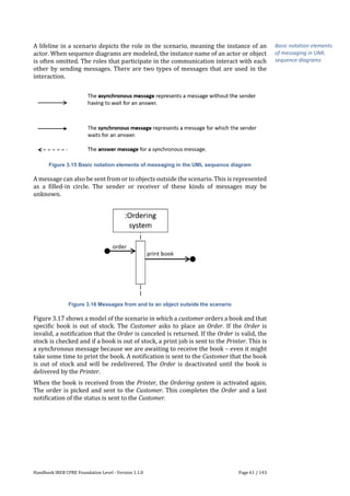
3.4.6.4 UML Sequence Diagram
The UML sequence diagram is used to depict the interaction between communication
partners and to model the dynamic aspect of systems. The dynamic aspect of systems
that a sequence diagram depict can be function & flow as well a state & behavior.
Therefore, a UML sequence diagram can be used for different purposes.
The communication partners in a UML sequence diagram are actors, systems,
components, and/or objects within a system. The interaction displays the sequence
of messages (a scenario) between these communication partners. The interaction that
takes place between the communication partners realizes the purpose of a scenario,
respectively (a part) of a use case.
In the overview below you will find the basic notation elements.
Figure 3.14 Basic notation elements of the UML sequence diagram
Basic notation elements
of UML sequence
diagrams](https://image.slidesharecdn.com/chapter3cprefoundationlevelhandbookgeneral-241003184941-f97fe9b6/85/Chapter_3_CPRE_FoundationLevel_Handbook_General-pdf-33-320.jpg)

![Handbook IREB CPRE Foundation Level - Version 1.1.0 Page 63 / 143
Creating, maintaining, and using a glossary consistently avoids errors and
misunderstandings concerning the terminology used. Working with glossaries is a
standard best practice in RE.
3.6 Requirements Documents and Documentation Structures
It is not sufficient to work with requirements at the level of individual requirements.
Requirements must be collated and grouped in suitable work products, be they
explicit requirements documents or other RE-related documentation structures
(such as a product backlog).
Document templates (see Section 3.3.3) may be used to organize such documents
with a well-defined structure in order to create a consistent and maintainable
collection of requirements. Document templates are available in literature
[Vole2020], [RoRo2012] and in standards [ISO29148]. Templates may also be reused
from previous, similar projects or may be imposed by a customer. An organization
may also decide to create a document template as an internal standard.
A requirements document may also contain additional information and
explanations—for example, a glossary, acceptance criteria, project information, or
characteristics of the technical implementation.
Frequently used requirements documents are:
Stakeholder requirements specification: the stakeholders’ desires and needs
that shall be satisfied by building a system, seen from the stakeholders’
perspective. When a customer writes a stakeholder requirements
specification, it is called a customer requirements specification.
User requirements specification: a subset of a stakeholder requirements
specification, covering only requirements of stakeholders who are
prospective users of a system.
System requirements specification: the requirements for a system to be built
and its context so that it satisfies its stakeholders’ desires and needs.
Business requirements specification: the business goals, objectives, and needs
of an organization that shall be achieved by employing a system (or a
collection of systems).
Vision document: a conceptual imagination of a future system, describing its
key characteristics and how it will create value for its users.
Frequently used alternative documentation structures are:
Product backlog: a prioritized list of work items, covering all requirements
that are needed and known for the product
Sprint backlog: a selected subset of a product backlog with work items that
will be realized in the next iteration
Story map: a visual two-dimensional organization of user stories in a product
backlog with respect to time and content
There is no standard or universal requirements document or documentation
structure. Accordingly, documents or documentation structures should not be reused
from previous projects without reflection.
Documents and
<documentation
structures
Document templates
Frequently used
documents
Frequently used
documentation
structures
Choosing a proper
documentation form](https://image.slidesharecdn.com/chapter3cprefoundationlevelhandbookgeneral-241003184941-f97fe9b6/85/Chapter_3_CPRE_FoundationLevel_Handbook_General-pdf-36-320.jpg)
![Handbook IREB CPRE Foundation Level - Version 1.1.0 Page 64 / 143
The actual choice depends on several factors, for example:
The development process chosen
The project type and domain (for example, tailor-made solution, product
development, or standard product customizing)
The contract (a customer may prescribe the use of a given documentation
structure)
The size of the document (the larger the document, the more structure is
needed)
3.7 Prototypes in Requirements Engineering
Prototypes play an important role both in engineering and design.
Definition 3.5 Prototype: 1. In manufacturing: A piece which is built prior to the start
of mass production. 2. In software and systems engineering: A preliminary, partial
realization of certain characteristics of a system. 3. In design: A preliminary, partial
instance of a design solution.
Prototypes in software and systems engineering are used for three major purposes
[LiSZ1994]:
Exploratory prototypes are used to create shared understanding, clarify requirements,
or validate requirements at different levels of fidelity. Such prototypes constitute
temporary work products that are discarded after use. Exploratory prototypes may
also be used as a means of specification by example. Such prototypes must be treated
as evolving or durable work products.
Experimental prototypes (also called breadboards) are used to explore technical
design solution concepts, in particular with respect to their technical feasibility. They
are discarded after use. Experimental prototypes are not used in RE.
Evolutionary prototypes are pilot systems that form the core of a system to be
developed. The final system evolves by incrementally extending and improving the
pilot system in several iterations. Agile system development frequently employs an
evolutionary prototyping approach.
Requirements Engineers primarily use exploratory prototypes as a means for
requirements elicitation and validation. In elicitation, prototypes serve as a means of
specification by example. In particular, when stakeholders cannot express what they
want clearly, a prototype can demonstrate what they would get, which helps them
shape their requirements. In validation, prototypes are a powerful means for
validating the adequacy (see Section 3.8) of requirements.
Exploratory prototypes can be built and used with different degrees of fidelity. We
distinguish between wireframes, mock-ups, and native prototypes.
Wireframes (also called paper prototypes) are low-fidelity prototypes built with
paper or other simple materials that serve primarily for discussing and validating
design ideas and user interface concepts. When prototyping digital systems,
wireframes may also be built with digital sketching tools or dedicated wireframing
tools. However, when using a digital tool for wireframing, it is important to retain the
essential properties of a wireframe: it can be built quickly, modified easily, and does
not look polished nor resemble a final product.
Prototype
Exploratory prototype
Experimental prototype
Evolutionary prototype
Prototypes in RE
Wireframe](https://image.slidesharecdn.com/chapter3cprefoundationlevelhandbookgeneral-241003184941-f97fe9b6/85/Chapter_3_CPRE_FoundationLevel_Handbook_General-pdf-37-320.jpg)

![Handbook IREB CPRE Foundation Level - Version 1.1.0 Page 66 / 143
Adequacy and understandability are the most important quality criteria. Without
them, a requirement is useless or even detrimental, regardless of the fulfillment of all
other criteria. Verifiability is important when the system implemented must undergo
a formal acceptance procedure.
Some people use correctness instead of adequacy. However, the notion of correctness
implies that there is a formal procedure for deciding whether something is correct or
not. As there is no formal procedure for validating a documented requirement against
the desires and needs that stakeholders have in mind, we prefer the term adequacy
over correctness.
For work products covering multiple requirements, we recommend applying the
following quality criteria:
Consistent: no two requirements, recorded in a single work product or in
different work products, contradict each other.
Non-redundant: each requirement is documented only once and does not
overlap with another requirement.
Complete: the work product contains all relevant requirements (functional
requirements, quality requirements, and constraints) that are known at this
point in time and that are related to this work product.
Modifiable: the work product is set up in such a way that it can be modified
without degrading its quality.
Traceable: the requirements in the work product can be traced back to their
origins, forward to their implementation (in design, code, and test), and to
other requirements they depend on.
Conformant: if there are mandatory structuring or formatting instructions,
the work product must conform to them.
3.9 Further Reading
Mavin et al. [MWHN2009] introduce and describe the EARS template. Robertson and
Robertson [RoRo2012] describe the Volere templates. Goetz and Rupp [GoRu2003],
[Rupp2014] discuss rules and pitfalls for writing requirements in natural language.
Cockburn [Cock2001] has written an entire book about how to write use cases.
Lauesen [Laue2002] discusses task descriptions and also provides some examples of
real-world RE work products.
The ISO/IEC/IEEE standard 29148 [ISO29148] provides many resources concerning
RE work products: phrase templates, quality criteria for requirements, and detailed
descriptions of the content of various RE work products, including a document
template for every work product. Cohn [Cohn2010] has a chapter on how to frame
requirements in a product backlog.
Gregory [Greg2016] and Glinz [Glin2016] discuss the problem of how detailed
requirements should be specified and to what extent complete and unambiguous
requirements specifications are possible.
Numerous publications deal with using models to specify requirements. The UML
specification [OMG2017], as well as textbooks about UML, describe the models
available in UML. Hofer and Schwentner [HoSch2020] introduce domain modeling
with domain storytelling. [OMG2013] and [OMG2018] describe the modeling
languages BPMN for modeling business processes and SysML for modeling systems,
respectively. The books by Booch, Rumbaugh, and Jacobson [BoRJ2005], [JaSB2011],
Quality criteria for RE
work products](https://image.slidesharecdn.com/chapter3cprefoundationlevelhandbookgeneral-241003184941-f97fe9b6/85/Chapter_3_CPRE_FoundationLevel_Handbook_General-pdf-39-320.jpg)
![Handbook IREB CPRE Foundation Level - Version 1.1.0 Page 67 / 143
[RuJB2004] give more depth and (practical) applications of UML. Furthermore, the
following books and articles are recommended for more thorough knowledge and
patterns in modeling requirements: [DaTW2012], [Davi1993], [Fowl1996],
[GHJV1994]. [LiSS1994] and [Pohl2010] provide a better understanding of the quality
aspects of models.](https://image.slidesharecdn.com/chapter3cprefoundationlevelhandbookgeneral-241003184941-f97fe9b6/85/Chapter_3_CPRE_FoundationLevel_Handbook_General-pdf-40-320.jpg)