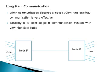
 Block Diagram of fiber optic communication, selection of optical
fiber types for short haul, long haul and
 high speed data links, optical power and dispersion budget
calculations of fiber optic communication link
 Repeaters,
 optical fiber amplifiers,
 optical fiber transmitter
 optical fiber receiver design considerations
 Draw block diagram of fiber optic
communication
Prepared by Mrs. Pallavi Mahagaonkar for TYB.Sc(Ele)
 When communication distance exceeds 10km, the long haul
communication is very effective.
 Basically it is point to point communication system with
very high data rates
Node P
Node Q
Users
Users
 Low Losses
Number of repeaters should be low to have very low loss
Repeater spacing is more as much as 40km
Due to which installation and maintenance cost is low
 For manufacturing a long fiber special care has to be taken during
fiber drawing
 Unbroken fiber length of 5 km
 This will reduce the number of splices to be used
 Due to which power loss will be minimum
 The cable used in long haul communication need to face or
withstand harsh environmental conditions so cable should be
structurally sound
 In long haul communication cable cannot be brought back to
the laboratory for repairs
 Hence it is expected that all the field components including
fiber cable must be field repairable
 It is the inherent property of the optical fiber to provide secure
and private transmission
 So care is to be taken to maintain the privacy and security
 Now that the losses for the link have been identified, the
power at the receiver, which is the power output of the link,
may be calculated simply as [EIRP] [LOSSES] [GR], where the
last quantity is the receiver antenna gain
 Note carefully that decibel addition must be used
 The major source of loss in any ground-satellite link is the
free-space spreading loss [FSL], the basic link-power budget
equation taking into account this loss only.
 However, the other losses also must be taken into account,
and these are simply added to [FSL]. The losses for clear-sky
conditions are
 [LOSSES] = [FSL] + [RFL] + [AML] + [AA] - [PL] equation for
the received power is then
 [PR] = [EIRP] x [GR] - [LOSSES]
where [PR] received power, dBW
[EIRP] --> equivalent isotropic radiated power, dBW [FSL]
free-space spreading loss, dB
[RFL] --> receiver feeder loss, dB
[AML] --> antenna misalignment loss, dB
[AA] --> atmospheric absorption loss, dB [PL] polarization
mismatch loss, dB

Chapter4.pptx

  • 1.
     Block Diagramof fiber optic communication, selection of optical fiber types for short haul, long haul and  high speed data links, optical power and dispersion budget calculations of fiber optic communication link  Repeaters,  optical fiber amplifiers,  optical fiber transmitter  optical fiber receiver design considerations
  • 2.
     Draw blockdiagram of fiber optic communication
  • 3.
    Prepared by Mrs.Pallavi Mahagaonkar for TYB.Sc(Ele)
  • 4.
     When communicationdistance exceeds 10km, the long haul communication is very effective.  Basically it is point to point communication system with very high data rates Node P Node Q Users Users
  • 5.
     Low Losses Numberof repeaters should be low to have very low loss Repeater spacing is more as much as 40km Due to which installation and maintenance cost is low
  • 6.
     For manufacturinga long fiber special care has to be taken during fiber drawing  Unbroken fiber length of 5 km  This will reduce the number of splices to be used  Due to which power loss will be minimum
  • 7.
     The cableused in long haul communication need to face or withstand harsh environmental conditions so cable should be structurally sound
  • 9.
     In longhaul communication cable cannot be brought back to the laboratory for repairs  Hence it is expected that all the field components including fiber cable must be field repairable
  • 10.
     It isthe inherent property of the optical fiber to provide secure and private transmission  So care is to be taken to maintain the privacy and security
  • 11.
     Now thatthe losses for the link have been identified, the power at the receiver, which is the power output of the link, may be calculated simply as [EIRP] [LOSSES] [GR], where the last quantity is the receiver antenna gain  Note carefully that decibel addition must be used  The major source of loss in any ground-satellite link is the free-space spreading loss [FSL], the basic link-power budget equation taking into account this loss only.  However, the other losses also must be taken into account, and these are simply added to [FSL]. The losses for clear-sky conditions are
  • 12.
     [LOSSES] =[FSL] + [RFL] + [AML] + [AA] - [PL] equation for the received power is then  [PR] = [EIRP] x [GR] - [LOSSES] where [PR] received power, dBW [EIRP] --> equivalent isotropic radiated power, dBW [FSL] free-space spreading loss, dB [RFL] --> receiver feeder loss, dB [AML] --> antenna misalignment loss, dB [AA] --> atmospheric absorption loss, dB [PL] polarization mismatch loss, dB